EP1355058A2 - Kühler für ein dem Hauptabgasstrom eines Verbrennnungsmotors entnommenes Abgas - Google Patents
Kühler für ein dem Hauptabgasstrom eines Verbrennnungsmotors entnommenes Abgas Download PDFInfo
- Publication number
- EP1355058A2 EP1355058A2 EP03006411A EP03006411A EP1355058A2 EP 1355058 A2 EP1355058 A2 EP 1355058A2 EP 03006411 A EP03006411 A EP 03006411A EP 03006411 A EP03006411 A EP 03006411A EP 1355058 A2 EP1355058 A2 EP 1355058A2
- Authority
- EP
- European Patent Office
- Prior art keywords
- exhaust gas
- cooler
- exhaust
- cooling
- exhaust pipe
- Prior art date
- Legal status (The legal status is an assumption and is not a legal conclusion. Google has not performed a legal analysis and makes no representation as to the accuracy of the status listed.)
- Withdrawn
Links
Images

Classifications
-
- F—MECHANICAL ENGINEERING; LIGHTING; HEATING; WEAPONS; BLASTING
- F28—HEAT EXCHANGE IN GENERAL
- F28D—HEAT-EXCHANGE APPARATUS, NOT PROVIDED FOR IN ANOTHER SUBCLASS, IN WHICH THE HEAT-EXCHANGE MEDIA DO NOT COME INTO DIRECT CONTACT
- F28D7/00—Heat-exchange apparatus having stationary tubular conduit assemblies for both heat-exchange media, the media being in contact with different sides of a conduit wall
- F28D7/06—Heat-exchange apparatus having stationary tubular conduit assemblies for both heat-exchange media, the media being in contact with different sides of a conduit wall the conduits having a single U-bend
-
- F—MECHANICAL ENGINEERING; LIGHTING; HEATING; WEAPONS; BLASTING
- F02—COMBUSTION ENGINES; HOT-GAS OR COMBUSTION-PRODUCT ENGINE PLANTS
- F02M—SUPPLYING COMBUSTION ENGINES IN GENERAL WITH COMBUSTIBLE MIXTURES OR CONSTITUENTS THEREOF
- F02M26/00—Engine-pertinent apparatus for adding exhaust gases to combustion-air, main fuel or fuel-air mixture, e.g. by exhaust gas recirculation [EGR] systems
- F02M26/02—EGR systems specially adapted for supercharged engines
- F02M26/04—EGR systems specially adapted for supercharged engines with a single turbocharger
- F02M26/05—High pressure loops, i.e. wherein recirculated exhaust gas is taken out from the exhaust system upstream of the turbine and reintroduced into the intake system downstream of the compressor
-
- F—MECHANICAL ENGINEERING; LIGHTING; HEATING; WEAPONS; BLASTING
- F02—COMBUSTION ENGINES; HOT-GAS OR COMBUSTION-PRODUCT ENGINE PLANTS
- F02M—SUPPLYING COMBUSTION ENGINES IN GENERAL WITH COMBUSTIBLE MIXTURES OR CONSTITUENTS THEREOF
- F02M26/00—Engine-pertinent apparatus for adding exhaust gases to combustion-air, main fuel or fuel-air mixture, e.g. by exhaust gas recirculation [EGR] systems
- F02M26/13—Arrangement or layout of EGR passages, e.g. in relation to specific engine parts or for incorporation of accessories
- F02M26/22—Arrangement or layout of EGR passages, e.g. in relation to specific engine parts or for incorporation of accessories with coolers in the recirculation passage
- F02M26/23—Layout, e.g. schematics
- F02M26/25—Layout, e.g. schematics with coolers having bypasses
- F02M26/26—Layout, e.g. schematics with coolers having bypasses characterised by details of the bypass valve
-
- F—MECHANICAL ENGINEERING; LIGHTING; HEATING; WEAPONS; BLASTING
- F02—COMBUSTION ENGINES; HOT-GAS OR COMBUSTION-PRODUCT ENGINE PLANTS
- F02M—SUPPLYING COMBUSTION ENGINES IN GENERAL WITH COMBUSTIBLE MIXTURES OR CONSTITUENTS THEREOF
- F02M26/00—Engine-pertinent apparatus for adding exhaust gases to combustion-air, main fuel or fuel-air mixture, e.g. by exhaust gas recirculation [EGR] systems
- F02M26/13—Arrangement or layout of EGR passages, e.g. in relation to specific engine parts or for incorporation of accessories
- F02M26/22—Arrangement or layout of EGR passages, e.g. in relation to specific engine parts or for incorporation of accessories with coolers in the recirculation passage
- F02M26/29—Constructional details of the coolers, e.g. pipes, plates, ribs, insulation or materials
- F02M26/32—Liquid-cooled heat exchangers
-
- F—MECHANICAL ENGINEERING; LIGHTING; HEATING; WEAPONS; BLASTING
- F28—HEAT EXCHANGE IN GENERAL
- F28F—DETAILS OF HEAT-EXCHANGE AND HEAT-TRANSFER APPARATUS, OF GENERAL APPLICATION
- F28F27/00—Control arrangements or safety devices specially adapted for heat-exchange or heat-transfer apparatus
- F28F27/02—Control arrangements or safety devices specially adapted for heat-exchange or heat-transfer apparatus for controlling the distribution of heat-exchange media between different channels
-
- F—MECHANICAL ENGINEERING; LIGHTING; HEATING; WEAPONS; BLASTING
- F02—COMBUSTION ENGINES; HOT-GAS OR COMBUSTION-PRODUCT ENGINE PLANTS
- F02B—INTERNAL-COMBUSTION PISTON ENGINES; COMBUSTION ENGINES IN GENERAL
- F02B29/00—Engines characterised by provision for charging or scavenging not provided for in groups F02B25/00, F02B27/00 or F02B33/00 - F02B39/00; Details thereof
- F02B29/04—Cooling of air intake supply
- F02B29/0406—Layout of the intake air cooling or coolant circuit
-
- F—MECHANICAL ENGINEERING; LIGHTING; HEATING; WEAPONS; BLASTING
- F28—HEAT EXCHANGE IN GENERAL
- F28F—DETAILS OF HEAT-EXCHANGE AND HEAT-TRANSFER APPARATUS, OF GENERAL APPLICATION
- F28F2250/00—Arrangements for modifying the flow of the heat exchange media, e.g. flow guiding means; Particular flow patterns
- F28F2250/06—Derivation channels, e.g. bypass
-
- F—MECHANICAL ENGINEERING; LIGHTING; HEATING; WEAPONS; BLASTING
- F28—HEAT EXCHANGE IN GENERAL
- F28F—DETAILS OF HEAT-EXCHANGE AND HEAT-TRANSFER APPARATUS, OF GENERAL APPLICATION
- F28F2265/00—Safety or protection arrangements; Arrangements for preventing malfunction
- F28F2265/26—Safety or protection arrangements; Arrangements for preventing malfunction for allowing differential expansion between elements
-
- Y—GENERAL TAGGING OF NEW TECHNOLOGICAL DEVELOPMENTS; GENERAL TAGGING OF CROSS-SECTIONAL TECHNOLOGIES SPANNING OVER SEVERAL SECTIONS OF THE IPC; TECHNICAL SUBJECTS COVERED BY FORMER USPC CROSS-REFERENCE ART COLLECTIONS [XRACs] AND DIGESTS
- Y02—TECHNOLOGIES OR APPLICATIONS FOR MITIGATION OR ADAPTATION AGAINST CLIMATE CHANGE
- Y02T—CLIMATE CHANGE MITIGATION TECHNOLOGIES RELATED TO TRANSPORTATION
- Y02T10/00—Road transport of goods or passengers
- Y02T10/10—Internal combustion engine [ICE] based vehicles
- Y02T10/12—Improving ICE efficiencies
Definitions
- the invention relates to a cooler for a main exhaust gas flow Exhaust gas taken from the internal combustion engine.
- NOx emissions from motor vehicles gradually reduced from year to year.
- internal engine measures can be taken. Further can reduce NOx emissions through lean NOx catalysts or can be achieved by water injection. These measures require however either higher fuel consumption or a second fuel.
- the cooled exhaust gas recirculation is more advantageous. Thereby particle emissions and fuel consumption can be achieved with the same NOx emission lower further. This is achieved by the main exhaust gas flow between the engine exhaust and the turbine of a turbocharger exhaust removed, then cooled by an engine coolant and finally the fresh air is mixed in again after an intercooler. To this Part of the exhaust gas is burned twice and it becomes the desired one Lowering effects achieved.
- plate coolers have been used to date, with additional cooler control valves flanged to them. These measures result in higher costs due to additional components and as a result also higher weights. In addition, the flanged radiator control valves a larger installation space is required.
- the invention is based on the object a cooler for the main exhaust gas flow of an internal combustion engine between taken from the engine outlet and a turbine of a turbocharger and after cooling the fresh air after an intercooler again admixed To create exhaust gas that significantly optimizes its efficiency is.
- the measure according to the invention at least within a cooler to design a part of the cooling pipes to be separable from the passage of the exhaust gas, the fact can be taken into account that the Engine operation in cold condition does not require cooled exhaust gas recirculation. Therefore, there is no or only a very limited heat exchange in the cooler carried out. The same applies to higher load ranges with a warm one Condition of an internal combustion engine.
- An embodiment of the basic inventive concept looks after Claim 2 before that to the exhaust pipe inside the cooler U-shaped Cooling pipes are connected with their two ends, one end the cooling pipes to the exhaust pipe can be closed.
- the cooling tubes are closed at at least one end, so that the Exhaust gas cannot flow through the cooling pipes and can be cooled.
- End of the U-shaped cooling tubes can be closed by a swivel flap.
- the swivel flap is adjustable between two positions. In one position it blocks the exhaust pipe so that the exhaust gas passes through the U-shaped cooling pipes flows and is cooled by the engine coolant. After the exhaust has flowed through the cooling pipes, it gets back into the exhaust pipe behind the Swing flap and from there into the fresh air flow. Closes the swivel flap one end of the U-shaped cooling tubes, all the exhaust gas flows without Cooling through the exhaust pipe.
- Another embodiment of the basic idea of the invention provides according to the features of claim 4 before that to the exhaust pipe a central tube of larger diameter and next to the central tube, in particular bundles, several parallel cooling tubes with it smaller diameters are connected, with the central tube opposite the exhaust pipe is closable.
- the cooling pipes open here at the End facing away from the exhaust pipe in a reducer, which is the overpass serves the exhaust gas from the cooling tube bundles in the fresh air flow.
- the flow cross section of the central tube corresponds approximately to the flow cross section of all cooling tubes. If the central pipe is closed off from the exhaust pipe, flows the exhaust gas from the exhaust pipe into the cooling tube bundle, from which the Cooling tubes cross-flowing engine coolant indirectly cooled and arrives cooled in the fresh air flow.
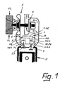
- FIG. 1, 1 is a schematically illustrated cooler for a main exhaust gas flow HAG of an internal combustion engine, also shown only schematically 2 between the engine outlet 3 and a turbine 4 of an exhaust gas turbocharger 5 removed and after cooling the fresh air FL after a charge air cooler 6 again admixed exhaust gas AG.
- the cooler 1a according to the embodiment in FIG. 2 comprises an exhaust pipe 7, on the one hand to a line illustrated only by an arrow 8 between the engine outlet 3 and the turbine 4 and on the other hand to one line 9, also illustrated only by an arrow, is connected, which leads the fresh air FL to the charge air cooler 6 (see also Figure 1).
- the exhaust pipe 7 is connected to a housing 10 in which there are several U-shaped cooling tubes 11 extend.
- the ends 12, 13 of the cooling tubes 11 are open to the exhaust pipe 7.
- the circumference of the ends 12, 13 is one Partition 14 is provided between the exhaust pipe 7 and the housing 10.
- the other end of the housing 10 is also closed by a wall 15.
- a pipe socket 16 is connected to the housing 10, via which according to the arrow 17, an engine coolant MKM is inserted into the housing 10, the Cooling tubes 11 flows across and after indirect heat exchange with the in the exhaust pipes AG led the cooling pipes 11, the housing 10 over another arcuate pipe socket 18 leaves according to the arrow 19.
- the ends 13 of the cooling tubes 11 can be closed by a swivel flap 20.
- the swing flap 20 is according to the arcuate double arrow 21 between a position in which it extends transversely in the exhaust pipe 7 and a second position in which it closes the ends 13 of the cooling tubes 11, adjustable. The adjustment is preferably not under the influence of one illustrated control.
- the swing flap 20 is transversely into the exhaust pipe 7 pivoted so that the exhaust gas AG via the ends 12 in the U-shaped cooling tubes 11 flows, there in a heat exchange with the engine coolant MKM is brought over after flowing through the cooling tubes 11 the ends 13 get back into the exhaust pipe 7 behind the swivel flap 20 and from here the fresh air FL flowing in line 9 after Charge air cooler 6 is added.
- the embodiment of a cooler 1b illustrated in FIG the main exhaust gas flow HAG of the internal combustion engine 2 between the engine outlet 3 and the turbine 4 and after cooling the Fresh air FL after the charge air cooler 6 again admixed exhaust gas AG also provides an exhaust pipe 22.
- the exhaust pipe 22 is in a manner not illustrated to the one illustrated only by an arrow 8 Line connected between the engine outlet 3 and the turbine 4.
- the other end 23 of the exhaust pipe 22 is closed.
- a central tube 24 extends transversely from the exhaust line 22 and extends into a Reducer 25 opens as part of a housing 26.
- the reducer 25 is in a manner not shown to the fresh air FL leading Line 9 is connected between the charge air cooler 6 and the engine inlet 27 (Fig. 1).
- central tube 24 In addition to the central tube 24, several bundled cooling tubes 28 each run a diameter that is compared to the diameter of the central tube 24 is significantly smaller.
- the flow cross section of the central tube 24 corresponds approximately the entire flow cross section of all cooling tubes 28.
- the cooling pipes 28 extend from the exhaust pipe 22 to the reducer 25th
- the housing 26 has a Feed pipe 33 and a discharge pipe 34, which one hand According to arrow 35, an engine coolant MKM the inside of the housing 26 supplied and after the heat exchange with exhaust gas AG according to arrow 36 is discharged again.
- a plug valve extends in the axial extension of the central tube 24 37, which corresponds to the double arrow 38 in the longitudinal axis 39 of the central tube 24 intersecting level is shiftable.
Landscapes
- Engineering & Computer Science (AREA)
- Mechanical Engineering (AREA)
- General Engineering & Computer Science (AREA)
- Chemical & Material Sciences (AREA)
- Combustion & Propulsion (AREA)
- Physics & Mathematics (AREA)
- Thermal Sciences (AREA)
- Exhaust-Gas Circulating Devices (AREA)
- Supercharger (AREA)
Abstract
Description
- Figur 1
- im Schema einen Verbrennungsmotor mit einem Abgasturbolader und einer Abgasrückkühleinheit;
- Figur 2
- im schematischen Längsschnitt einen Kühler für ein dem Hauptabgasstrom des Verbrennungsmotors entnommenes Abgas und
- Figur 3
- ebenfalls im vertikalen Längsschnitt eine weitere Ausführungsform eines Kühlers für ein dem Hauptabgasstrom des Verbrennungsmotors entnommenes Abgas.
- 1 -
- Kühler
- 1 a -
- Kühler
- 1 b -
- Kühler
- 2 -
- Verbrennungsmotor
- 3 -
- Motorauslass
- 4 -
- Turbine v. 5
- 5 -
- Abgasturbolader
- 6 -
- Ladeluftkühler
- 7 -
- Abgasleitung v. 1a
- 8 -
- Leitung zw. 3 u. 4
- 9 -
- Leitung zw. 6 u. 23
- 10 -
- Gehäuse v. 1a
- 11 -
- Kühlrohre in 10
- 12 -
- Enden v. 11
- 13 -
- Enden v. 11
- 14 -
- Trennwand in 10
- 15 -
- Wand v. 10
- 16 -
- Rohrstutzen an 10
- 17 -
- Pfeil
- 18 -
- Rohrstutzen an 10
- 19 -
- Pfeil
- 20 -
- Schwenkklappe in 7
- 21 -
- Doppelpfeil
- 22 -
- Abgasleitung
- 23 -
- Ende v. 22
- 24 -
- Zentralrohr v. 1b
- 25 -
- Reduzierstück v. 26
- 26 -
- Gehäuse v. 1b
- 27 -
- Motoreinlass
- 28 -
- Kühlrohre in 1b
- 29 -
- Enden v. 28
- 30 -
- Trennwand
- 31 -
- Enden von 28
- 32 -
- Trennwand
- 33 -
- Zuführstutzen
- 34 -
- Abführstutzen
- 35 -
- Pfeil
- 36 -
- Pfeil
- 37 -
- Stopfenschieber
- 38 -
- Doppelpfeil
- 39 -
- Längsachse v. 24
- 40 -
- Ende v. 24
- 41 -
- Stopfen v. 37
- AG -
- Abgas
- FL -
- Frischluft
- HAG -
- Hauptabgasstrom
- MKM -
- Motorkühlmittel
Claims (6)
- Kühler für ein dem Hauptabgasstrom (HAG) eines Verbrennungsmotors (2) zwischen dem Motorauslass (3) und einer Turbine (4) eines Abgasturboladers (5) entnommenes und nach der Kühlung der Frischluft (FL) nach einem Ladeluftkühler (6) wieder beigemischtes Abgas (AG), welcher von einer Abgasleitung (7, 22) abzweigende Kühlrohre (11; 28) aufweist, die von einem Motorkühlmittel (MKM) quer angeströmt sind, wobei mindestens ein Teil der Kühlrohre (11; 28) von der Durchleitung des Abgases (AG) abtrennbar ist.
- Kühler nach Patentanspruch 1, bei welchem an die Abgasleitung (7) U-förmige Kühlrohre (11) mit ihren beiden Enden (12, 13) angeschlossen sind, wobei ein Ende (13) der Kühlrohre (11) zur Abgasleitung (7) hin verschließbar ist.
- Kühler nach Patentanspruch 2, bei welchem ein Ende (13) der U-förmigen Kühlrohre (11) durch eine Schwenkklappe (20) verschließbar ist.
- Kühler nach Patentanspruch 1, bei welchem an die an einem Ende (23) verschlossene Abgasleitung (22) ein Zentralrohr (24) größeren Durchmessers und neben dem Zentralrohr (24) mehrere parallele Kühlrohre (28) mit demgegenüber kleineren Durchmessern angeschlossen sind, wobei das Zentralrohr (24) gegenüber der Abgasleitung (22) verschließbar ist.
- Kühler nach Patentanspruch 4, bei welchem das Zentralrohr (24) durch einen axial verlagerbaren Stopfen (41) als Bestandteil eines Stopfenschiebers (37) verschließbar ist.
- Kühler nach einem der Patentansprüche 1 bis 5, welcher aus Edelstahl besteht.
Applications Claiming Priority (2)
| Application Number | Priority Date | Filing Date | Title |
|---|---|---|---|
| DE10216773A DE10216773B4 (de) | 2002-04-15 | 2002-04-15 | Kühler für ein dem Hauptabgasstrom eines Verbrennungsmotors entnommenes Abgas |
| DE10216773 | 2002-04-15 |
Publications (2)
| Publication Number | Publication Date |
|---|---|
| EP1355058A2 true EP1355058A2 (de) | 2003-10-22 |
| EP1355058A3 EP1355058A3 (de) | 2006-06-21 |
Family
ID=28458858
Family Applications (1)
| Application Number | Title | Priority Date | Filing Date |
|---|---|---|---|
| EP03006411A Withdrawn EP1355058A3 (de) | 2002-04-15 | 2003-03-21 | Kühler für ein dem Hauptabgasstrom eines Verbrennnungsmotors entnommenes Abgas |
Country Status (2)
| Country | Link |
|---|---|
| EP (1) | EP1355058A3 (de) |
| DE (1) | DE10216773B4 (de) |
Cited By (9)
| Publication number | Priority date | Publication date | Assignee | Title |
|---|---|---|---|---|
| AT413442B (de) * | 2004-06-03 | 2006-02-15 | Avl List Gmbh | Kühleinrichtung |
| WO2007104491A1 (de) * | 2006-03-10 | 2007-09-20 | Behr Gmbh & Co. Kg | Wärmetauscher für ein kraftfahrzeug |
| WO2007082676A3 (de) * | 2006-01-19 | 2007-10-18 | Behr Gmbh & Co Kg | Vorrichtung zur abgaskühlung |
| WO2008058737A1 (de) * | 2006-11-15 | 2008-05-22 | Behr Gmbh & Co. Kg | Abgasrückführeinrichtung |
| EP2017455A1 (de) | 2007-06-21 | 2009-01-21 | T.RAD Co,.Ltd | AGR-Kühlvorrichtung |
| US20090090486A1 (en) * | 2006-03-16 | 2009-04-09 | Behr Gmbh & Co. Kg | Heat exchanger for a motor vehicle |
| CN101163876B (zh) * | 2005-02-08 | 2010-05-26 | 黛叩恩萨有限责任公司 | 旁通阀 |
| FR2989998A1 (fr) * | 2012-04-26 | 2013-11-01 | Faurecia Sys Echappement | Dispositif de recuperation de chaleur pour ligne d'echappement |
| WO2016016052A1 (de) * | 2014-07-28 | 2016-02-04 | Tenneco Gmbh | Ventilgehäuse und ventil |
Families Citing this family (5)
| Publication number | Priority date | Publication date | Assignee | Title |
|---|---|---|---|---|
| DE102005041150A1 (de) * | 2005-07-19 | 2007-01-25 | Behr Gmbh & Co. Kg | Wärmeübertragerventileinrichtung |
| DE102005041149A1 (de) * | 2005-07-19 | 2007-02-01 | Behr Gmbh & Co. Kg | Wärmeübertragerventileinrichtung |
| JP4468277B2 (ja) * | 2005-10-03 | 2010-05-26 | 愛三工業株式会社 | 流路切替弁 |
| DE102007015146B4 (de) | 2007-03-29 | 2009-12-10 | Benteler Automobiltechnik Gmbh | Aluminium System Kühler |
| DE102017003380A1 (de) * | 2017-04-06 | 2018-10-11 | Linde Aktiengesellschaft | Wärmetauscher, Verwendung eines Wärmetauschers und Verfahren zur Herstellung eines Wärmetauschers |
Family Cites Families (9)
| Publication number | Priority date | Publication date | Assignee | Title |
|---|---|---|---|---|
| DE914450C (de) * | 1943-01-14 | 1954-07-01 | Hans Windhoff App Und Maschine | Vorrichtung zum Kuehlen der Auspuffgase von Brennkraftmaschinen, insbesondere fuer Motorlokomotiven |
| DE4430648A1 (de) * | 1994-08-29 | 1996-03-07 | Flucorrex Ag Flawil | Verfahren zum Regeln der Austrittstemperatur eines zu erwärmenden Mediums auf einen vorbestimmten Temperaturwert in einem Rekuperator, Rekuperator und Verwendung eines derartigen Rekuperators |
| US5617726A (en) * | 1995-03-31 | 1997-04-08 | Cummins Engine Company, Inc. | Cooled exhaust gas recirculation system with load and ambient bypasses |
| FR2776015B1 (fr) * | 1998-03-11 | 2000-08-11 | Ecia Equip Composants Ind Auto | Organe d'echappement a echangeur de chaleur |
| DE19841927A1 (de) * | 1998-09-14 | 2000-03-16 | Wahler Gmbh & Co Gustav | Einrichtung zur Rückführung eines Abgasstromes zum Saugrohr einer Brennkraftmaschine |
| KR20010102981A (ko) * | 1999-01-20 | 2001-11-17 | 산쿄 레디에이터 가부시키 가이샤 | Egr 쿨러 |
| DE10018503A1 (de) * | 2000-04-14 | 2001-10-18 | Pierburg Ag | Abgasrückführeinrichtung für eine Brennkraftmaschine |
| WO2002052142A1 (fr) * | 2000-12-19 | 2002-07-04 | Valeo Termico Sa | Module echangeur de chaleur, specialement concu pour un systeme de recyclage des gaz d'echappement |
| ATE339610T1 (de) * | 2001-07-18 | 2006-10-15 | Cooper Standard Automotive D | Kühler eines abgasrückführsystems sowie abgasrückführsystem mit einem derartigen kühler |
-
2002
- 2002-04-15 DE DE10216773A patent/DE10216773B4/de not_active Revoked
-
2003
- 2003-03-21 EP EP03006411A patent/EP1355058A3/de not_active Withdrawn
Cited By (17)
| Publication number | Priority date | Publication date | Assignee | Title |
|---|---|---|---|---|
| AT413442B (de) * | 2004-06-03 | 2006-02-15 | Avl List Gmbh | Kühleinrichtung |
| CN101163876B (zh) * | 2005-02-08 | 2010-05-26 | 黛叩恩萨有限责任公司 | 旁通阀 |
| US7836868B2 (en) | 2005-02-08 | 2010-11-23 | Borgwarner Emissions Systems Spain, S.L. | By-pass valve |
| WO2007082676A3 (de) * | 2006-01-19 | 2007-10-18 | Behr Gmbh & Co Kg | Vorrichtung zur abgaskühlung |
| WO2007104491A1 (de) * | 2006-03-10 | 2007-09-20 | Behr Gmbh & Co. Kg | Wärmetauscher für ein kraftfahrzeug |
| US8573286B2 (en) | 2006-03-10 | 2013-11-05 | Behr Gmbh & Co. Kg | Heat exchanger for a motor vehicle |
| CN101400959B (zh) * | 2006-03-16 | 2010-09-29 | 贝洱两合公司 | 用于汽车的热交换器 |
| US20090090486A1 (en) * | 2006-03-16 | 2009-04-09 | Behr Gmbh & Co. Kg | Heat exchanger for a motor vehicle |
| US8544454B2 (en) | 2006-03-16 | 2013-10-01 | Behr Gmbh & Co. Kg | Heat exchanger for a motor vehicle |
| WO2008058737A1 (de) * | 2006-11-15 | 2008-05-22 | Behr Gmbh & Co. Kg | Abgasrückführeinrichtung |
| CN101329142B (zh) * | 2007-06-21 | 2010-04-21 | 株式会社T.Rad | Egr冷却器 |
| EP2017455A1 (de) | 2007-06-21 | 2009-01-21 | T.RAD Co,.Ltd | AGR-Kühlvorrichtung |
| FR2989998A1 (fr) * | 2012-04-26 | 2013-11-01 | Faurecia Sys Echappement | Dispositif de recuperation de chaleur pour ligne d'echappement |
| WO2016016052A1 (de) * | 2014-07-28 | 2016-02-04 | Tenneco Gmbh | Ventilgehäuse und ventil |
| CN106662264A (zh) * | 2014-07-28 | 2017-05-10 | 天纳克有限责任公司 | 阀壳体以及阀 |
| US10041389B2 (en) | 2014-07-28 | 2018-08-07 | Tenneco Gmbh | Valve housing and valve |
| CN106662264B (zh) * | 2014-07-28 | 2018-12-14 | 天纳克有限责任公司 | 阀壳体以及阀 |
Also Published As
| Publication number | Publication date |
|---|---|
| DE10216773A1 (de) | 2003-11-06 |
| EP1355058A3 (de) | 2006-06-21 |
| DE10216773B4 (de) | 2004-09-16 |
Similar Documents
| Publication | Publication Date | Title |
|---|---|---|
| EP2129888B1 (de) | Ladefluidansaugmodul und verbrennungskraftmaschine | |
| DE69815882T2 (de) | Anlage einer brennkraftmaschine | |
| AT411546B (de) | Flüssigkeitsgekühlte brennkraftmaschine mit abgasrückführeinrichtung und einer vorrichtung zur kühlung rückgeführten abgases | |
| DE102011052454B4 (de) | Verfahren zur steuerung eines zwischenkühlers und ein kühlsystem eines fahrzeugs | |
| EP1355058A2 (de) | Kühler für ein dem Hauptabgasstrom eines Verbrennnungsmotors entnommenes Abgas | |
| EP2456969B1 (de) | Brennkraftmaschine und frischluftanlage | |
| EP2302190B1 (de) | Abgasrückführsystem | |
| EP2108807B1 (de) | Abgasrückführsystem für eine Verbrennungskraftmaschine | |
| EP2025911B1 (de) | Abgaskühlvorrichtung für eine Verbrennungskraftmaschine | |
| EP1132609A2 (de) | Abgaswärmetauscher in einer Abgasrückführungsanordnung | |
| WO2008101978A1 (de) | Frischgasmodul für eine frischgasanlage | |
| EP1870591A2 (de) | Sauganlage für eine Brennkraftmaschine | |
| DE112012005979T5 (de) | Verbrennungsmotor | |
| DE602004001578T2 (de) | Turboaufgeladener Dieselmotor mit langwegigem Abgasrückführsystem | |
| EP2077387A1 (de) | Verfahren zur Kühlung eines rückzuführenden Abgasstroms einer Brennkraftmaschine | |
| DE102006049392B4 (de) | Abgasemissionssteuersystem für eine Verbrennungsmaschine | |
| DE102014204031B4 (de) | Abgasrückführungsvorrichtung für Fahrzeugmotoren | |
| DE102005006055A1 (de) | Wärmetauscher | |
| EP0778919B1 (de) | Variable luftansaugvorrichtung | |
| DE102019206450B4 (de) | Motorsystem | |
| DE102015206898A1 (de) | Abgasrückführungsmodul mit regelbarem Bypass sowie Zylinderkopf mit einem solchen Abgasrückführungsmodul | |
| EP1727976B1 (de) | Brennkraftmaschine mit befeuchtungseinrichtung und wärmetauscher | |
| EP3295014A1 (de) | Vorrichtung und verfahren zur abgasrückführung | |
| DE102021115406B3 (de) | Verbrennungskraftmaschine umfassend eine Sekundärlufteinrichtung | |
| EP3085942B1 (de) | Abgasrückführungsmodul mit austauschbarer wärmetauscherkassette |
Legal Events
| Date | Code | Title | Description |
|---|---|---|---|
| PUAI | Public reference made under article 153(3) epc to a published international application that has entered the european phase |
Free format text: ORIGINAL CODE: 0009012 |
|
| AK | Designated contracting states |
Kind code of ref document: A2 Designated state(s): AT BE BG CH CY CZ DE DK EE ES FI FR GB GR HU IE IT LI LU MC NL PT RO SE SI SK TR |
|
| AX | Request for extension of the european patent |
Extension state: AL LT LV MK |
|
| PUAL | Search report despatched |
Free format text: ORIGINAL CODE: 0009013 |
|
| AK | Designated contracting states |
Kind code of ref document: A3 Designated state(s): AT BE BG CH CY CZ DE DK EE ES FI FR GB GR HU IE IT LI LU MC NL PT RO SE SI SK TR |
|
| AX | Request for extension of the european patent |
Extension state: AL LT LV MK |
|
| AKX | Designation fees paid |
Designated state(s): AT BE BG CH CY CZ DE DK EE ES FI FR GB GR HU IE IT LI LU MC NL PT RO SE SI SK TR |
|
| STAA | Information on the status of an ep patent application or granted ep patent |
Free format text: STATUS: THE APPLICATION IS DEEMED TO BE WITHDRAWN |
|
| 18D | Application deemed to be withdrawn |
Effective date: 20061222 |