EP1353518A1 - Procédé et système pour la génération des images stéréoscopiques à partir d'images monoculaires - Google Patents
Procédé et système pour la génération des images stéréoscopiques à partir d'images monoculaires Download PDFInfo
- Publication number
- EP1353518A1 EP1353518A1 EP02425218A EP02425218A EP1353518A1 EP 1353518 A1 EP1353518 A1 EP 1353518A1 EP 02425218 A EP02425218 A EP 02425218A EP 02425218 A EP02425218 A EP 02425218A EP 1353518 A1 EP1353518 A1 EP 1353518A1
- Authority
- EP
- European Patent Office
- Prior art keywords
- image
- pixels
- stereoscopic effect
- monocular image
- movement
- Prior art date
- Legal status (The legal status is an assumption and is not a legal conclusion. Google has not performed a legal analysis and makes no representation as to the accuracy of the status listed.)
- Withdrawn
Links
Images


Classifications
-
- H—ELECTRICITY
- H04—ELECTRIC COMMUNICATION TECHNIQUE
- H04N—PICTORIAL COMMUNICATION, e.g. TELEVISION
- H04N13/00—Stereoscopic video systems; Multi-view video systems; Details thereof
- H04N13/20—Image signal generators
- H04N13/261—Image signal generators with monoscopic-to-stereoscopic image conversion
-
- H—ELECTRICITY
- H04—ELECTRIC COMMUNICATION TECHNIQUE
- H04N—PICTORIAL COMMUNICATION, e.g. TELEVISION
- H04N13/00—Stereoscopic video systems; Multi-view video systems; Details thereof
- H04N13/10—Processing, recording or transmission of stereoscopic or multi-view image signals
- H04N13/106—Processing image signals
- H04N13/122—Improving the 3D impression of stereoscopic images by modifying image signal contents, e.g. by filtering or adding monoscopic depth cues
-
- H—ELECTRICITY
- H04—ELECTRIC COMMUNICATION TECHNIQUE
- H04N—PICTORIAL COMMUNICATION, e.g. TELEVISION
- H04N13/00—Stereoscopic video systems; Multi-view video systems; Details thereof
- H04N13/10—Processing, recording or transmission of stereoscopic or multi-view image signals
- H04N13/106—Processing image signals
- H04N13/128—Adjusting depth or disparity
-
- H—ELECTRICITY
- H04—ELECTRIC COMMUNICATION TECHNIQUE
- H04N—PICTORIAL COMMUNICATION, e.g. TELEVISION
- H04N13/00—Stereoscopic video systems; Multi-view video systems; Details thereof
- H04N13/20—Image signal generators
- H04N13/204—Image signal generators using stereoscopic image cameras
- H04N13/239—Image signal generators using stereoscopic image cameras using two 2D image sensors having a relative position equal to or related to the interocular distance
-
- H—ELECTRICITY
- H04—ELECTRIC COMMUNICATION TECHNIQUE
- H04N—PICTORIAL COMMUNICATION, e.g. TELEVISION
- H04N13/00—Stereoscopic video systems; Multi-view video systems; Details thereof
- H04N13/20—Image signal generators
- H04N13/286—Image signal generators having separate monoscopic and stereoscopic modes
-
- H—ELECTRICITY
- H04—ELECTRIC COMMUNICATION TECHNIQUE
- H04N—PICTORIAL COMMUNICATION, e.g. TELEVISION
- H04N13/00—Stereoscopic video systems; Multi-view video systems; Details thereof
- H04N2013/0074—Stereoscopic image analysis
- H04N2013/0081—Depth or disparity estimation from stereoscopic image signals
Definitions
- the present invention relates to the art of stereoscopic vision, and in particular tackles the problem of reconstructing the stereoscopic vision of objects from the availability of monocular vision of these objects and the relative depth map.
- the photo When a photograph is acquired, for example using a camera, the photo provides a two-dimensional image of the scene in which the depth information and distance between objects (or the different regions of the scene) are not present. By looking at these two-dimensional images, an observer may virtually reconstruct the depth information through previously acquired knowledge of the world represented in this photo.
- retinal disparity can be easily understood with reference to a simple experiment: hold the thumb of one hand in front of your face and observe it.
- Disparity is the distance, in a horizontal direction, between the corresponding right and left points of the superimposed retinic images.
- the corresponding points of the retinal images of an object on which the eyes are converged have zero disparity.
- Retinal disparity is caused by the fact that each eye sees the world from a different view point. Eyes are, on average in adults, spaced apart by about 64 mm (this distance between the right and left eyes is called base line or interocular distance).
- Disparity is processed by the eye-brain system into a single image of the visual world.
- the capacity of the mind to unite two different images, even if similar, into one single image is called fusion, and the resulting sense of depth is called stereopsis.
- parallax and disparity are similar entities, with the difference given by the fact that the parallax is measured on the screen and the disparity is measured on the retina. It is the parallax that produces retinal disparity and the disparity in turn which produces stereopsis. Parallax may also be given in terms of angular measurements, which connects it to the disparity considering the distance of the observer from the viewing screen. Parallax is an important entity, as it produces the stereoscopic sense of depth.
- Projection for the left eye LE is to the left and projection for the right eye RE is to the right.
- the distance between the right and left projections of the eye is called horizontal parallax PO.
- the maximum positive parallax PO is obtained when the object is infinite. At this point, the horizontal parallax PO is equal to the base line or interocular distance.
- the distance between the objectives used to take a stereoscopic photograph is called interaxial distance, as regards the axes of the lenses.
- the axis of the objective is the line that can be drawn through the optic centre of the objective and is perpendicular to the plane of the surface on which the image is formed.
- the interaxial distance may be considered as coinciding with the interocular distance when the eye is considered as an image acquiring system.
- WO-A-01/39512 describes a device destined to convert a two-dimensional video image into a three-dimensional video image.
- the device comprises means to correct the parallax of each area calculated by means to calculate the parallax on the basis of the magnitude of a moving vector.
- This solution is used to avoid the disadvantage caused by the fact that the stereoscopic sense of the video signal obtained by conversion is strongly influenced, with the same input video signal, as a function of the criteria employed to convert the video signal.
- the document in question refers to prior art procedures such as MTD (Modified Time Difference) and CID (Computed Image Depth).
- a depth estimate When a depth estimate is converted into a parallax, the estimate in question is subjected to a conversion of the distances scale so as to suppress the distortion of the image resulting from conversion and to determine, at least at tentative level, a target phase for each calculation area of the parallax.
- a dynamic field is identified in which the differences in phase between the parallax calculation areas are within an admissible change of distortion, producing a conversion of the distances scale, also determining, again at tentative level, a target phase and repeating this processing sequence.
- the object of the invention is thus to provide a solution for the generation of stereoscopic images from monocular images capable of giving rise to extremely satisfactory results from the viewpoint of quality. All this giving rise to a processing system architecture that allows easy implementation at a physical level, in particular at the level of hardware devices.
- the invention also relates to the relative system.
- the solution according to the invention allows the generation of the stereoscopic pair from a single source image of the monocular type and from the relative depth information.
- This image or depth map is an image with levels of grey (for example with values from 0 to 255 - therefore on eight bits), which represents the depth of each object within the source image.
- the conjunction of the source image and the depth map allow reconstruction of the binocular view, thus producing a three-dimensional effect.
- a final filtering treatment makes it possible to solve the "occlusions", generated by introducing the parallax effect, without however introducing visible and/or bothersome artefacts.
- This process is preferably performed on the basis of all the three-dimensional coordinates of the objects inside the image.
- Each object, each dot, each figure is then identified, divided, separated, calculated and so on, also knowing the parameters of the acquisition system (for example the parameters of the camera or television camera).
- the parameters of the acquisition system for example the parameters of the camera or television camera.
- the solution according to the invention envisages the performance of three classes of operations: acquisition, reconstruction (or processing) and viewing.
- the solution according to the invention is susceptible to prescind from the input information referring to the concept of the depth map, which is susceptible to provide at least the form, the position of the objects and the relative depth in the scene.
- this selection may include the choice of anaglyphs.
- the first step is to define the source view point: in other words, to decide if the two final images (right and left) must be recreated from nothing having that source of reference, or if the source image is to be exactly one of the final images while only the other is to be reconstructed from it.
- the first action is the one most suited for the final phase of reconstruction by means of applying the parallax.
- this does not imply a restriction or differentiation of the conversion problem.
- the present invention hereunder proposes a solution to limit visibility of the artefacts, not by using special functions to mask these but by variable modification of a reduction/enlargement factor of the depth perception inside the viewing device.
- the first two elements are useful in order to generate images with dimensions congruous with the device utilized for viewing.
- the third element can be easily calculated having the first two elements and using the viewing specifications of the human eye.
- the fourth (namely the depth of the objects) is instead an essential element on which reconstruction of the three-dimensional environment from the two-dimensional projection is based.
- the present invention utilizes the concept of depth map for this purpose.
- the depth map in practice the link existing between two-dimensional and three-dimensional worlds (or what is sometimes defined two-and-a-half dimensions or 2D 1 ⁇ 2), is a mapping of the objects present in an image in relation to their spatial position.
- This mapping may alternatively have two meanings.
- the first identifies the exact correspondence of the space of each dot of the image, and in this case may be defined as depth map.
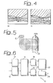
- this is an image with different levels of grey in which each area reproduced with a specific level of grey (shown in figure 4 with different sectioning) identifies the positioning, within the extent of the image, of objects or of a group of objects t found in a certain distance range in relation to the observation point.
- both images of figure 4 reproduce different depth maps of an image of a mountain panorama (essentially the view of a valley).
- the overall effect that can be deduced by observing the depth map is almost similar to the effect perceivable by observing a group of stage settings or by observing a mountain landscape at daybreak or dusk in conditions in which the reduced level of luminosity makes chromatic information difficult to perceive and, at the same time, the grazing illumination of the sun low on the horizon highlights the staggering, on various subsequent perspective planes, of the raised areas included in the landscape.
- the phenomenon is linked to so-called depth perception and is inversely proportional to distance from the object in question. Therefore the problem is posed of how to correctly define a depth map that complies with this rule.
- Figure 5 illustrates a typical effect of perception of three-dimensional or 3D space, identifying, on the one hand, equidistant levels of depth EL and the relative perception PER.
- Figure 5 defines several levels of depth equidistant from one another, so that the initial rule is not violated. This also means that a real depth map can be emulated with an appropriate disparity map. In other words, even if we do not know the real three-dimensional position of the objects, but by judiciously distributing each object on different levels equidistant from one another, it is possible to generate -- a -- depth effect very similar to the real one: in this respect, it must again be mentioned that the object set by the solution according to the invention is to reconstruct three-dimensionality of the scene and not exactly the real one.
- This task may be facilitated by analysis of the initial image in the temporal domain.
- this analysis might never reveal the original information that we are attempting to reconstruct. This is due, for example, to the fact that a certain object (or usually a certain portion of this) might never be visible during the entire sequence, irrespective of the number of images considered.
- a technique that may be suggested to decrease the presence and/or visibility of these artefacts is one that, by limiting as much as possible a magnitude of the holes on the final images and maintaining the visual three-dimensional effect, fills or fills in these holes or gaps with the original information in the homologous positions.
- Figure 6 illustrates in the form of a block diagram the architecture of a system for the reconstruction of a three-dimensional scene according to the criteria set forth above.
- the aforesaid system indicated as a whole with 10, comprises corresponding modules that perform the following functions:
- Module 12 is composed mainly of data memorizing structures (of the known kind) in which the two-dimensional images destined to be placed at the disposal of the other processing blocks present in the system are loaded. No general limits are set on the quantity of the images that can be loaded.
- a typical example of these processing methods is given by the techniques for processing images based on the use of neural networks which, for their matrix structure, are suitable to be coupled directly to image sensors which also have a matrix structure.
- Module 14 implements acquisition of the depth map connected to the image or images input into the system through module 12. As already mentioned, the present invention does not specifically relate to the generation of the aforesaid depth map, which may be made available to the system described herein employing any prior art solution for this purpose. Clearly, the quantity of depth data loaded in module 14 must correspond to the quantity of source data loaded in module 12.
- One of the parameters to be considered in three-dimensional reconstruction is correlation between the quantity of parallax to obtain the three-dimensional effect and the quantity of pixels corresponding to it.
- the parallax value as a function of the interocular distance must be converted into a specific quantity of pixels to move data horizontally to the right and left. It is therefore necessary to determine the correct conversion function that considers the two systems different to value the pixel/distance ratio (usually expressed in millimetres).
- the images will be viewed on the dedicated screen, with a fixed dimension and fixed resolution. It may thus be assumed that, by observing the three-dimensional image with the full screen, the image must also have the same dimension and resolution as the video. If this is not the case, the final image must be processed (according to prior art which does not require to be described herein) so that it is then aligned with these values.
- Pixel/mm (X px .Y px ) / (W mm .H mm ) where the input image has [X:Y] pixels and where the final screen has the dimensions [W:H].
- the original pixel and its replica must be moved (horizontally) by a quantity defined by the parallax value to be applied.
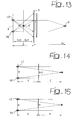
- the diagram in figure 7 illustrates, in the form of a functional block diagram, the criteria used to calculate the final parallax.
- references 26 and 28 illustrate the data (which can be seen as data files) containing the information relative to the interocular distance and the decrease in depth (file 26) and the image length, the image width and the diagonal dimension of the video (file 28).
- the block 30 represents the functional module which determines the distance and resolution, in particular generating the information relative to the minimum user-screen distance (intended as the minimum distance at which the image is viewed on the screen comfortably for the human vision system, distances greater than this minimum value increase the comfort of viewing but give increasingly less depth perception) and the pixels/millimetres ratio seen previously.
- a module indicated with 32 calculates, on the basis of the data contained in file 26, the parallax, intended as maximum parallax.
- the block 34 indicates the module destined to act as parallax motor destined to feed towards a module acting as movement motor, indicated with 36, the movement information (right left) relative to the parallax.
- the module 36 generates the left image LI and the right image RI destined to be sent to modules 18 and 20 of figure 6.
- the block or module 30 assesses two important parameters: the minimum distance recommended to the user to view the screen in comfort and the resolution of the image as pixel/millimetre ratio.
- Block or module 32 assesses the maximum parallax value M that can be obtained in relation to the interocular distance, indicated with B, and to the depth effect desired (F(D)).
- Block 36 is instead the true movement motor, which must take account of the distribution of the total parallax value.
- the parallax value must also be divided into two parts.
- Each of these parts generally corresponds to a fraction of the overall movement and can therefore be either extremely different from or equal to each other (for example, by being equal to half of the overall movement).
- a black edge is also present due to the lack of information to enter in the corresponding lateral bands.
- the dimension of this edge depends principally on the parallax. In particular, it depends on the maximum parallax value of those pixels that do not fall inside the image.
- the dimension of the edges that remain blacked does not depend on the value of the maximum parallax applied to the image, but on the maximum parallax that the pixels may have.
- the maximum parallax defines the extent of the maximum depth effect of the screen.
- this value will never be reached. Therefore, there is a direct and proportional dependence with the content of the depth map.
- Figure 11 illustrates an example in which, after a left movement, it is no longer possible to establish and state with certainty which values the pixels to the right of D and to the left of E must have.
- the depth map associated to the source. As has already been seen, the depth map forms the connection between the two-dimensional source at the three-dimensional output.
- the object sought here is not to reconstruct the natural three-dimensional effect, but to manage a three-dimensional effect, capable of managing all types of map, thus capable of manipulating the three-dimensional effect as required: this feature is of particular importance, for example, in entertainment applications or medical and scientific applications.
- the value of the parallax can be seen as a function of the interocular distance B. This is mainly true when it is asserted that the parallax cannot be greater than B in the cases in which:
- variable distance can be defined, with a minimum value equal to D, at which the observer must be positioned from the screen S, while it is possible to define the depth inside the screen as variable.
- the next step is to define the best scale function to associate to each value of the depth map the corresponding parallax value M to be associated to each pixel.
- the maximum parallax is associated to the objects furthest away, while the minimum parallax is associated to those nearest.
- the minimum value for N is 2 as a higher parallax value is not possible. Therefore the maximum parallax and the depth of the screen are made to depend on the reduction value N.
- a reference value of N to obtain comfortable three-dimensional vision can be obtained through experimental tests.
- the variability of the depth effect is connected to the programmable reduction factor N of the three-dimensional effect desired.
- the value N has a fundamental role in creating the occlusions in the construction process of the two right and left images so that as N decreases there is an increase in the magnitude of the holes between originally adjacent objects and an increase in the dimension of the lateral edge of the image that is blacked.
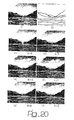
- Figure 20 indicates various possible results of three-dimensional reconstruction of an original image a) from a depth map indicated with b).
- N the greater the maximum parallax is, causing less comfortable three-dimensional vision of the anaglyph. It is obvious that, as a function of the application, it is possible to choose a correct compromise between the value of N and a comfortable three-dimensional vision, in particular as regards the non-perception of holes and gaps.
Priority Applications (1)
| Application Number | Priority Date | Filing Date | Title |
|---|---|---|---|
| EP02425218A EP1353518A1 (fr) | 2002-04-09 | 2002-04-09 | Procédé et système pour la génération des images stéréoscopiques à partir d'images monoculaires |
Applications Claiming Priority (1)
| Application Number | Priority Date | Filing Date | Title |
|---|---|---|---|
| EP02425218A EP1353518A1 (fr) | 2002-04-09 | 2002-04-09 | Procédé et système pour la génération des images stéréoscopiques à partir d'images monoculaires |
Publications (1)
| Publication Number | Publication Date |
|---|---|
| EP1353518A1 true EP1353518A1 (fr) | 2003-10-15 |
Family
ID=28051898
Family Applications (1)
| Application Number | Title | Priority Date | Filing Date |
|---|---|---|---|
| EP02425218A Withdrawn EP1353518A1 (fr) | 2002-04-09 | 2002-04-09 | Procédé et système pour la génération des images stéréoscopiques à partir d'images monoculaires |
Country Status (1)
| Country | Link |
|---|---|
| EP (1) | EP1353518A1 (fr) |
Cited By (11)
| Publication number | Priority date | Publication date | Assignee | Title |
|---|---|---|---|---|
| US7822265B2 (en) * | 2004-04-14 | 2010-10-26 | Koninklijke Philips Electronics N.V. | Ghost artifact reduction for rendering 2.5D graphics |
| WO2011097050A2 (fr) | 2010-02-02 | 2011-08-11 | Microsoft Corporation | Compatibilité de caméra de profondeur |
| US20110304618A1 (en) * | 2010-06-14 | 2011-12-15 | Qualcomm Incorporated | Calculating disparity for three-dimensional images |
| US8508550B1 (en) * | 2008-06-10 | 2013-08-13 | Pixar | Selective rendering of objects |
| WO2011028837A3 (fr) * | 2009-09-01 | 2014-03-27 | Prime Focus Vfx Services Ii Inc. | Système et processus de transformation d'images bidimensionnelles en images tridimensionnelles |
| CN105608666A (zh) * | 2015-12-25 | 2016-05-25 | 普瑞福克斯(北京)数字媒体科技有限公司 | 一种二维图形生成三维图像的方法及系统 |
| US9378575B1 (en) | 2013-11-05 | 2016-06-28 | Pixar | Chained kinematic logic |
| CN111383257A (zh) * | 2018-12-29 | 2020-07-07 | 顺丰科技有限公司 | 一种车厢装卸率确定方法和装置 |
| CN112380963A (zh) * | 2020-11-11 | 2021-02-19 | 东软睿驰汽车技术(沈阳)有限公司 | 基于全景环视系统的深度信息确定方法和装置 |
| CN113538546A (zh) * | 2021-09-17 | 2021-10-22 | 智道网联科技(北京)有限公司 | 用于自动驾驶的目标检测方法、装置及设备 |
| CN117061720A (zh) * | 2023-10-11 | 2023-11-14 | 广州市大湾区虚拟现实研究院 | 基于单目图像及深度图像渲染的立体图像对生成方法 |
Citations (2)
| Publication number | Priority date | Publication date | Assignee | Title |
|---|---|---|---|---|
| US5929859A (en) * | 1995-12-19 | 1999-07-27 | U.S. Philips Corporation | Parallactic depth-dependent pixel shifts |
| US6031538A (en) * | 1994-08-30 | 2000-02-29 | Thomson Broadband Systems | Method for the generation of synthetic images |
-
2002
- 2002-04-09 EP EP02425218A patent/EP1353518A1/fr not_active Withdrawn
Patent Citations (2)
| Publication number | Priority date | Publication date | Assignee | Title |
|---|---|---|---|---|
| US6031538A (en) * | 1994-08-30 | 2000-02-29 | Thomson Broadband Systems | Method for the generation of synthetic images |
| US5929859A (en) * | 1995-12-19 | 1999-07-27 | U.S. Philips Corporation | Parallactic depth-dependent pixel shifts |
Cited By (19)
| Publication number | Priority date | Publication date | Assignee | Title |
|---|---|---|---|---|
| US7822265B2 (en) * | 2004-04-14 | 2010-10-26 | Koninklijke Philips Electronics N.V. | Ghost artifact reduction for rendering 2.5D graphics |
| US8508550B1 (en) * | 2008-06-10 | 2013-08-13 | Pixar | Selective rendering of objects |
| US8922628B2 (en) | 2009-09-01 | 2014-12-30 | Prime Focus Vfx Services Ii Inc. | System and process for transforming two-dimensional images into three-dimensional images |
| WO2011028837A3 (fr) * | 2009-09-01 | 2014-03-27 | Prime Focus Vfx Services Ii Inc. | Système et processus de transformation d'images bidimensionnelles en images tridimensionnelles |
| EP2531980A2 (fr) * | 2010-02-02 | 2012-12-12 | Microsoft Corporation | Compatibilité de caméra de profondeur |
| CN102741887A (zh) * | 2010-02-02 | 2012-10-17 | 微软公司 | 深度相机兼容性 |
| US8619122B2 (en) | 2010-02-02 | 2013-12-31 | Microsoft Corporation | Depth camera compatibility |
| WO2011097050A2 (fr) | 2010-02-02 | 2011-08-11 | Microsoft Corporation | Compatibilité de caméra de profondeur |
| CN102741887B (zh) * | 2010-02-02 | 2016-05-18 | 微软技术许可有限责任公司 | 深度相机兼容性 |
| EP2531980A4 (fr) * | 2010-02-02 | 2013-06-05 | Microsoft Corp | Compatibilité de caméra de profondeur |
| US20110304618A1 (en) * | 2010-06-14 | 2011-12-15 | Qualcomm Incorporated | Calculating disparity for three-dimensional images |
| US9378575B1 (en) | 2013-11-05 | 2016-06-28 | Pixar | Chained kinematic logic |
| CN105608666A (zh) * | 2015-12-25 | 2016-05-25 | 普瑞福克斯(北京)数字媒体科技有限公司 | 一种二维图形生成三维图像的方法及系统 |
| CN111383257A (zh) * | 2018-12-29 | 2020-07-07 | 顺丰科技有限公司 | 一种车厢装卸率确定方法和装置 |
| CN112380963A (zh) * | 2020-11-11 | 2021-02-19 | 东软睿驰汽车技术(沈阳)有限公司 | 基于全景环视系统的深度信息确定方法和装置 |
| CN113538546A (zh) * | 2021-09-17 | 2021-10-22 | 智道网联科技(北京)有限公司 | 用于自动驾驶的目标检测方法、装置及设备 |
| CN113538546B (zh) * | 2021-09-17 | 2022-01-25 | 智道网联科技(北京)有限公司 | 用于自动驾驶的目标检测方法、装置及设备 |
| CN117061720A (zh) * | 2023-10-11 | 2023-11-14 | 广州市大湾区虚拟现实研究院 | 基于单目图像及深度图像渲染的立体图像对生成方法 |
| CN117061720B (zh) * | 2023-10-11 | 2024-03-01 | 广州市大湾区虚拟现实研究院 | 基于单目图像及深度图像渲染的立体图像对生成方法 |
Similar Documents
| Publication | Publication Date | Title |
|---|---|---|
| EP1704730B1 (fr) | Procede et appareil destines a generer une image stereoscopique | |
| KR101629479B1 (ko) | 능동 부화소 렌더링 방식 고밀도 다시점 영상 표시 시스템 및 방법 | |
| EP2357841B1 (fr) | Procédé et appareil de traitement d'images tridimensionnelles | |
| US8369607B2 (en) | Method and apparatus for processing three-dimensional images | |
| CN108141578B (zh) | 呈现相机 | |
| US8749660B2 (en) | Image recording apparatus and image processing method | |
| US7321374B2 (en) | Method and device for the generation of 3-D images | |
| US8798160B2 (en) | Method and apparatus for adjusting parallax in three-dimensional video | |
| JP4995092B2 (ja) | ステレオカメラの画像の歪み補正装置、及びその方法 | |
| EP1771014A1 (fr) | Procede et dispositif de creation d'image stereoscopique | |
| KR20110083650A (ko) | 신호에 포함된 시차 정보를 처리하는 방법 | |
| US10631008B2 (en) | Multi-camera image coding | |
| JP6585938B2 (ja) | 立体像奥行き変換装置およびそのプログラム | |
| JP6128442B2 (ja) | 立体画像および画像シーケンスのステレオベース拡張のための方法および装置{method and device for stereo base extension of stereoscopic images and image sequences} | |
| JP6300346B2 (ja) | Ip立体映像推定装置及びそのプログラム | |
| EP1353518A1 (fr) | Procédé et système pour la génération des images stéréoscopiques à partir d'images monoculaires | |
| JP2016225811A (ja) | 画像処理装置、画像処理方法およびプログラム | |
| KR100672925B1 (ko) | 적응적 시차 추정 방식을 이용한 다시점 영상 생성 방법 | |
| JP6113411B2 (ja) | 画像処理装置 | |
| KR100433276B1 (ko) | 입체 영상 표시 장치 | |
| KR20020037097A (ko) | 신호처리를 이용한 주시각 제어 장치 및 그 방법과 그를이용한 평행축 입체 카메라 시스템 | |
| JPWO2012176526A1 (ja) | 立体画像処理装置、立体画像処理方法、及びプログラム | |
| JP4270695B2 (ja) | 立体画像表示装置用2dー3d画像変換方式および装置 | |
| KR101192121B1 (ko) | 양안시차 및 깊이 정보를 이용한 애너그리프 영상 생성 방법 및 장치 | |
| Laldin | Perceived Acceleration in Stereoscopic Animation |
Legal Events
| Date | Code | Title | Description |
|---|---|---|---|
| PUAI | Public reference made under article 153(3) epc to a published international application that has entered the european phase |
Free format text: ORIGINAL CODE: 0009012 |
|
| AK | Designated contracting states |
Kind code of ref document: A1 Designated state(s): AT BE CH CY DE DK ES FI FR GB GR IE IT LI LU MC NL PT SE TR |
|
| AX | Request for extension of the european patent |
Extension state: AL LT LV MK RO SI |
|
| AKX | Designation fees paid | ||
| REG | Reference to a national code |
Ref country code: DE Ref legal event code: 8566 |
|
| STAA | Information on the status of an ep patent application or granted ep patent |
Free format text: STATUS: THE APPLICATION IS DEEMED TO BE WITHDRAWN |
|
| 18D | Application deemed to be withdrawn |
Effective date: 20040416 |