EP1353054A1 - Turboprop-Flugzeugtriebwerk - Google Patents
Turboprop-Flugzeugtriebwerk Download PDFInfo
- Publication number
- EP1353054A1 EP1353054A1 EP20030003686 EP03003686A EP1353054A1 EP 1353054 A1 EP1353054 A1 EP 1353054A1 EP 20030003686 EP20030003686 EP 20030003686 EP 03003686 A EP03003686 A EP 03003686A EP 1353054 A1 EP1353054 A1 EP 1353054A1
- Authority
- EP
- European Patent Office
- Prior art keywords
- compressor
- air
- aircraft engine
- inlet
- turboprop aircraft
- Prior art date
- Legal status (The legal status is an assumption and is not a legal conclusion. Google has not performed a legal analysis and makes no representation as to the accuracy of the status listed.)
- Granted
Links
- 230000001419 dependent effect Effects 0.000 abstract 1
- 230000015572 biosynthetic process Effects 0.000 description 3
- 238000010276 construction Methods 0.000 description 3
- 230000006866 deterioration Effects 0.000 description 3
- 239000002245 particle Substances 0.000 description 3
- 230000000694 effects Effects 0.000 description 2
- 230000003993 interaction Effects 0.000 description 2
- 238000010420 art technique Methods 0.000 description 1
- 239000012530 fluid Substances 0.000 description 1
- 239000000446 fuel Substances 0.000 description 1
- 238000000926 separation method Methods 0.000 description 1
- 238000007493 shaping process Methods 0.000 description 1
Images


Classifications
-
- F—MECHANICAL ENGINEERING; LIGHTING; HEATING; WEAPONS; BLASTING
- F02—COMBUSTION ENGINES; HOT-GAS OR COMBUSTION-PRODUCT ENGINE PLANTS
- F02C—GAS-TURBINE PLANTS; AIR INTAKES FOR JET-PROPULSION PLANTS; CONTROLLING FUEL SUPPLY IN AIR-BREATHING JET-PROPULSION PLANTS
- F02C7/00—Features, components parts, details or accessories, not provided for in, or of interest apart form groups F02C1/00 - F02C6/00; Air intakes for jet-propulsion plants
- F02C7/04—Air intakes for gas-turbine plants or jet-propulsion plants
- F02C7/05—Air intakes for gas-turbine plants or jet-propulsion plants having provisions for obviating the penetration of damaging objects or particles
- F02C7/052—Air intakes for gas-turbine plants or jet-propulsion plants having provisions for obviating the penetration of damaging objects or particles with dust-separation devices
-
- B—PERFORMING OPERATIONS; TRANSPORTING
- B64—AIRCRAFT; AVIATION; COSMONAUTICS
- B64D—EQUIPMENT FOR FITTING IN OR TO AIRCRAFT; FLIGHT SUITS; PARACHUTES; ARRANGEMENT OR MOUNTING OF POWER PLANTS OR PROPULSION TRANSMISSIONS IN AIRCRAFT
- B64D33/00—Arrangements in aircraft of power plant parts or auxiliaries not otherwise provided for
- B64D33/02—Arrangements in aircraft of power plant parts or auxiliaries not otherwise provided for of combustion air intakes
-
- F—MECHANICAL ENGINEERING; LIGHTING; HEATING; WEAPONS; BLASTING
- F02—COMBUSTION ENGINES; HOT-GAS OR COMBUSTION-PRODUCT ENGINE PLANTS
- F02C—GAS-TURBINE PLANTS; AIR INTAKES FOR JET-PROPULSION PLANTS; CONTROLLING FUEL SUPPLY IN AIR-BREATHING JET-PROPULSION PLANTS
- F02C7/00—Features, components parts, details or accessories, not provided for in, or of interest apart form groups F02C1/00 - F02C6/00; Air intakes for jet-propulsion plants
- F02C7/04—Air intakes for gas-turbine plants or jet-propulsion plants
-
- F—MECHANICAL ENGINEERING; LIGHTING; HEATING; WEAPONS; BLASTING
- F05—INDEXING SCHEMES RELATING TO ENGINES OR PUMPS IN VARIOUS SUBCLASSES OF CLASSES F01-F04
- F05D—INDEXING SCHEME FOR ASPECTS RELATING TO NON-POSITIVE-DISPLACEMENT MACHINES OR ENGINES, GAS-TURBINES OR JET-PROPULSION PLANTS
- F05D2220/00—Application
- F05D2220/30—Application in turbines
- F05D2220/32—Application in turbines in gas turbines
- F05D2220/323—Application in turbines in gas turbines for aircraft propulsion, e.g. jet engines
-
- Y—GENERAL TAGGING OF NEW TECHNOLOGICAL DEVELOPMENTS; GENERAL TAGGING OF CROSS-SECTIONAL TECHNOLOGIES SPANNING OVER SEVERAL SECTIONS OF THE IPC; TECHNICAL SUBJECTS COVERED BY FORMER USPC CROSS-REFERENCE ART COLLECTIONS [XRACs] AND DIGESTS
- Y02—TECHNOLOGIES OR APPLICATIONS FOR MITIGATION OR ADAPTATION AGAINST CLIMATE CHANGE
- Y02T—CLIMATE CHANGE MITIGATION TECHNOLOGIES RELATED TO TRANSPORTATION
- Y02T50/00—Aeronautics or air transport
- Y02T50/60—Efficient propulsion technologies, e.g. for aircraft
-
- Y—GENERAL TAGGING OF NEW TECHNOLOGICAL DEVELOPMENTS; GENERAL TAGGING OF CROSS-SECTIONAL TECHNOLOGIES SPANNING OVER SEVERAL SECTIONS OF THE IPC; TECHNICAL SUBJECTS COVERED BY FORMER USPC CROSS-REFERENCE ART COLLECTIONS [XRACs] AND DIGESTS
- Y10—TECHNICAL SUBJECTS COVERED BY FORMER USPC
- Y10T—TECHNICAL SUBJECTS COVERED BY FORMER US CLASSIFICATION
- Y10T137/00—Fluid handling
- Y10T137/0536—Highspeed fluid intake means [e.g., jet engine intake]
Definitions
- the invention relates to a turboprop aircraft engine with an external air inlet as well as with an adjoining inner duct system for feeding from air to a compressor.
- the air required by the turboprop aircraft engine is fed through at least one outer air inlet and subsequently the compressor through an internal channel system fed.
- Such air intakes can either only be an outer one Air intake and only one assigned duct system or several include.
- the state of the art shows these air duct systems as Chin inlets or Scoop inlets. This can be multi-flow or branched (e.g. the double-flow inlet or bifurcated inlet).
- the constructive in the prior art Design of the walls of the air supply are designed accordingly.
- the entire system of both the outer air intake as well as the connected inner channel system is designed so that the air duct is parallel to the central axis of the engine (machine axis).
- the entrance guide wheel of the compressor then directs the flow into one suitable direction for the compressor in which it is the Air flow a corresponding circumferential component in the direction of rotation imposed on the compressor.
- the invention is based on the object of a turboprop aircraft engine of the type mentioned at the beginning, that the air supply to the compressor takes place without losses can and at the same time the stable operation of the Compressor is supported.
- the object is characterized by the features of Main claim solved, the sub-claims show more advantageous embodiments of the invention.
- the at least one inner channel system to the central axis of the engine helical is trained.
- the configuration according to the invention is characterized by a A number of significant advantages.
- the special shape of the duct system means that Air flow from the outside air inlet to the compressor is advantageous Way influenced.
- Another significant advantage of the invention then lies before if the direction of rotation of the propeller is identical to that of the compressor.
- the special supports Shaping the direction of rotation of the air flow.
- the swirl of the incoming air flow is maintained and optimized accordingly, resulting in an improved Inflow to the compressor, especially the inlet area of the compressor results.
- Air intake system so that the through the propeller introduced twist is largely preserved.
- the inner channel system as well as in preferred Training the outside air intake towards aligned with the swirling flow.
- the specific one Course of the air supply system according to the invention (angle of rotation depending on the axial position on the central axis of the engine) can thus be based on the conservation of angular momentum fluid mechanics can be optimized.
- the constructive design of the corresponding Channels and air ducts thus follow the swirl shape the air flow, there is a "twisted duct".
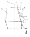
- FIG. 5 an outer air inlet 1 is shown on the an inner channel system connects. 1 to 4 only begin with the representation of the narrowest flow cross section 5, they show in detail the inner channel system 2.
- the central axis of the engine is with the reference symbol 3 provided.
- the air inlet has a narrowest flow cross section 5, which merges into a diffuser 6.
- a compressor not shown.
- a particle separator 10 is also provided (device for separating the particles introduced with the flow), the extension of the diffuser part (diffuser 6) is arranged.
- the helical shape already described results or corkscrew-like design.
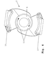
- the Figures 1, 3 and 4 show with the parts in a schematic Representation of the twist direction 11, in which the entire arrangement is twisted about the central axis 3.
Landscapes
- Engineering & Computer Science (AREA)
- Chemical & Material Sciences (AREA)
- Combustion & Propulsion (AREA)
- Mechanical Engineering (AREA)
- General Engineering & Computer Science (AREA)
- Aviation & Aerospace Engineering (AREA)
- Structures Of Non-Positive Displacement Pumps (AREA)
Abstract
Description
- Fig. 1
- eine schematische perspektivische Darstellung des erfindungsgemäßen Luftführungssystems mit äußerem Lufteinlass und innerem Kanalsystem,
- Fig. 2
- eine Draufsicht auf die Ausgestaltung gemäß Fig. 1,
- Fig. 3
- eine Vorderansicht der Anordnung gemäß den Fig. 1 und 2,
- Fig. 4
- eine Rückansicht der in den Fig. 1 bis 3 gezeigten Ausgestaltungsform, und
- Fig. 5
- eine schematische Seiten-Schnittansicht des Luftführungssystems.
- 1
- Äußerer Lufteinlass (= Einlauflippe)
- 2
- Inneres Kanalsystem
- 3 4
- Mittelachse
- 5
- Engster Strömungsquerschnitt
- 6
- Diffusor
- 7
- Umlenkung
- 8
- Konfusor
- 9
- Ringkanal
- 10
- Partikelseparator
- 11
- Drallrichtung
Claims (6)
- Turboprop-Flugzeugtriebwerk mit zumindest einem äußeren Lufteinlass (1) sowie mit zumindest einem sich daran anschließenden inneren Kanalsystem (2) zur Zuführung von Luft zu einem Kompressor, dadurch gekennzeichnet, dass das innere Kanalsystem (2) zur Mittelachse (3) des Triebwerks schraubenlinienförmig ausgebildet ist.
- Turboprop-Flugzeugtriebwerk nach Anspruch 1, dadurch gekennzeichnet, dass das innere Kanalsystem (2) schraubenlinienförmig zur Mittelachse (3) des Triebwerks ausgebildet ist.
- Turboprop-Flugzeugtriebwerk nach einem der Ansprüche 1 oder 2, dadurch gekennzeichnet, dass ein Verdrehwinkel der schraubenlinienförmigen Ausgestaltung in Abhängigkeit von dem durch den Propeller eingebrachten Drall der Luftströmung bestimmt ist.
- Turboprop-Flugzeugtriebwerk nach Anspruch 3, dadurch gekennzeichnet, dass der Verdrehwinkel zur Erhaltung des durch den Propeller eingebrachten Dralls der Luftströmung bestimmt ist.
- Turboprop-Flugzeugtriebwerk nach einem der Ansprüche 3 oder 4, dadurch gekennzeichnet, dass der Verdrehwinkel in Richtung des Dralls der in den äußeren Lufteinlass (1) strömenden Luft ausgerichtet ist.
- Turboprop-Flugzeugtriebwerk nach einem der Ansprüche 1 bis 5, dadurch gekennzeichnet, dass der Kompressor kein Eintrittslaufrad umfasst.
Applications Claiming Priority (2)
| Application Number | Priority Date | Filing Date | Title |
|---|---|---|---|
| DE2002115551 DE10215551A1 (de) | 2002-04-09 | 2002-04-09 | Turboprop-Flugzeugtriebwerk |
| DE10215551 | 2002-04-09 |
Publications (2)
| Publication Number | Publication Date |
|---|---|
| EP1353054A1 true EP1353054A1 (de) | 2003-10-15 |
| EP1353054B1 EP1353054B1 (de) | 2005-09-21 |
Family
ID=28051223
Family Applications (1)
| Application Number | Title | Priority Date | Filing Date |
|---|---|---|---|
| EP20030003686 Expired - Fee Related EP1353054B1 (de) | 2002-04-09 | 2003-02-18 | Turboprop-Flugzeugtriebwerk |
Country Status (4)
| Country | Link |
|---|---|
| US (1) | US6746207B1 (de) |
| EP (1) | EP1353054B1 (de) |
| CA (1) | CA2424497C (de) |
| DE (2) | DE10215551A1 (de) |
Families Citing this family (4)
| Publication number | Priority date | Publication date | Assignee | Title |
|---|---|---|---|---|
| WO2010077241A1 (en) | 2008-12-30 | 2010-07-08 | Sikorsky Aircraft Corporation | Engine air particle separator |
| GB2540169B (en) * | 2015-07-08 | 2018-08-08 | Ge Aviation Systems Llc | Aircraft wing shaped to counter aerodynamic effects of propeller wake |
| CN109098860A (zh) * | 2017-06-21 | 2018-12-28 | 杨航 | 一种动力装置 |
| US11994064B2 (en) | 2022-10-31 | 2024-05-28 | Pratt & Whitney Canada Corp. | Systems and methods for controlling an intake inlet shape of a propulsion system air intake |
Citations (2)
| Publication number | Priority date | Publication date | Assignee | Title |
|---|---|---|---|---|
| US5483791A (en) * | 1994-06-14 | 1996-01-16 | Alliedsignal Inc. | Turboprop with impeller inlet strake |
| US5725180A (en) * | 1995-12-29 | 1998-03-10 | General Electric Company | Aircraft engine pitot plenum intake |
Family Cites Families (10)
| Publication number | Priority date | Publication date | Assignee | Title |
|---|---|---|---|---|
| DE866144C (de) * | 1944-12-14 | 1953-02-09 | Daimler Benz Ag | Strahltriebwerksanordnung, insbesondere fuer Luftfahrzeuge |
| GB881720A (en) * | 1957-03-19 | 1961-11-08 | Bristol Siddeley Engines Ltd | Improvements in or relating to air supply units |
| US4397431A (en) * | 1981-11-02 | 1983-08-09 | Avco Corporation | Fail-safe, anti-icing system for aircraft engines |
| US4527387A (en) | 1982-11-26 | 1985-07-09 | General Electric Company | Particle separator scroll vanes |
| US4607657A (en) * | 1985-10-28 | 1986-08-26 | General Electric Company | Aircraft engine inlet |
| DE3828834C1 (de) | 1988-08-25 | 1989-11-02 | Mtu Muenchen Gmbh | |
| US4938021A (en) * | 1988-10-27 | 1990-07-03 | Sundstrand Corporation | Sustainer propulsion system |
| US5150569A (en) * | 1990-12-14 | 1992-09-29 | Williams International Corporation | Integrated propulsion system |
| US5961067A (en) * | 1996-09-10 | 1999-10-05 | Allison Engine Company | Method for reducing turboprop noise |
| WO2001083297A2 (en) * | 2000-05-04 | 2001-11-08 | Jangshik Yun | Aircraft gas turbine engine having a centrifuge |
-
2002
- 2002-04-09 DE DE2002115551 patent/DE10215551A1/de not_active Withdrawn
-
2003
- 2003-02-18 EP EP20030003686 patent/EP1353054B1/de not_active Expired - Fee Related
- 2003-02-18 DE DE50301210T patent/DE50301210D1/de not_active Expired - Lifetime
- 2003-04-04 CA CA002424497A patent/CA2424497C/en not_active Expired - Fee Related
- 2003-04-09 US US10/409,196 patent/US6746207B1/en not_active Expired - Lifetime
Patent Citations (2)
| Publication number | Priority date | Publication date | Assignee | Title |
|---|---|---|---|---|
| US5483791A (en) * | 1994-06-14 | 1996-01-16 | Alliedsignal Inc. | Turboprop with impeller inlet strake |
| US5725180A (en) * | 1995-12-29 | 1998-03-10 | General Electric Company | Aircraft engine pitot plenum intake |
Also Published As
| Publication number | Publication date |
|---|---|
| CA2424497C (en) | 2007-08-14 |
| DE50301210D1 (de) | 2006-02-02 |
| US6746207B1 (en) | 2004-06-08 |
| CA2424497A1 (en) | 2003-10-09 |
| DE10215551A1 (de) | 2003-10-23 |
| EP1353054B1 (de) | 2005-09-21 |
Similar Documents
| Publication | Publication Date | Title |
|---|---|---|
| DE60124572T2 (de) | Halbaxial- und kreiselverdichter für ein gasturbinentriebwerk | |
| EP2226473B1 (de) | Luftleitelement eines Laufspalteinstellungssystems einer Fluggasturbine | |
| DE19820097C2 (de) | Anordnung zur Grenzschichtabsaugung und Stoßgrenzschichtkontrolle für ein Flugzeug | |
| CH647042A5 (de) | Abdampfstutzen einer turbine. | |
| EP1318272A2 (de) | Kühlluftwirbelgleichrichter im Hochdruckverdichterrotor einer Gasturbine | |
| DE4422700A1 (de) | Diffusor für Turbomaschine | |
| EP0126399A1 (de) | Strömungskanal kurzer Baulänge | |
| EP1609999A2 (de) | Strömungsarbeitsmaschine | |
| EP0802305A1 (de) | Abgasturbolader für eine Brennkraftmaschine | |
| EP1789653A1 (de) | Rotor f]r ein triebwerk | |
| WO2008092427A1 (de) | Gasturbine mit einem nachleitkranz und mit einem mischer | |
| WO2011151323A2 (de) | Kanal mit strömungsleitfläche | |
| DE102017130568A1 (de) | Schubdüse für ein Turbofan-Triebwerk eines Überschallflugzeugs | |
| WO2008155023A1 (de) | Luftversorger, insbesondere für ein luftversorgungssystem von brennstoffzellen | |
| EP3234337A1 (de) | Luftleitung für einen ansaugtrakt einer verbrennungskraftmaschine, insbesondere eines kraftwagens | |
| DE102011012039A1 (de) | Kanal mit Strömungsleitfläche | |
| DE3813202A1 (de) | Waermetauscher | |
| EP1445193A1 (de) | Turbopropantrieb mit zwei mitläufigen und axial versetzten Propeller | |
| EP1323633B1 (de) | Lufteinlasssystem eines PTL-Antriebs | |
| EP3568597B1 (de) | Rückführstufe und radialturbofluidenergiemaschine | |
| EP1353054A1 (de) | Turboprop-Flugzeugtriebwerk | |
| DE102017217328A1 (de) | Düse mit axialer Verlängerung für eine Brennkammer eines Triebwerks | |
| CH652450A5 (de) | Turbinen-auspuffstutzen. | |
| EP2225467B1 (de) | Drallerzeugungsapparat und turbolader mit einem solchen drallerzeugungsapparat | |
| DE102019220089A1 (de) | Düsenelement für einen Strahlventilator und Strahlventilator |
Legal Events
| Date | Code | Title | Description |
|---|---|---|---|
| PUAI | Public reference made under article 153(3) epc to a published international application that has entered the european phase |
Free format text: ORIGINAL CODE: 0009012 |
|
| AK | Designated contracting states |
Kind code of ref document: A1 Designated state(s): AT BE BG CH CY CZ DE DK EE ES FI FR GB GR HU IE IT LI LU MC NL PT SE SI SK TR |
|
| AX | Request for extension of the european patent |
Extension state: AL LT LV MK RO |
|
| 17P | Request for examination filed |
Effective date: 20040415 |
|
| AKX | Designation fees paid |
Designated state(s): DE ES FR GB |
|
| 17Q | First examination report despatched |
Effective date: 20040609 |
|
| GRAP | Despatch of communication of intention to grant a patent |
Free format text: ORIGINAL CODE: EPIDOSNIGR1 |
|
| GRAS | Grant fee paid |
Free format text: ORIGINAL CODE: EPIDOSNIGR3 |
|
| GRAA | (expected) grant |
Free format text: ORIGINAL CODE: 0009210 |
|
| AK | Designated contracting states |
Kind code of ref document: B1 Designated state(s): DE ES FR GB |
|
| RBV | Designated contracting states (corrected) |
Designated state(s): DE ES FR GB |
|
| REG | Reference to a national code |
Ref country code: GB Ref legal event code: FG4D Free format text: NOT ENGLISH |
|
| GBT | Gb: translation of ep patent filed (gb section 77(6)(a)/1977) |
Effective date: 20050921 |
|
| REF | Corresponds to: |
Ref document number: 50301210 Country of ref document: DE Date of ref document: 20051027 Kind code of ref document: P |
|
| PG25 | Lapsed in a contracting state [announced via postgrant information from national office to epo] |
Ref country code: ES Free format text: LAPSE BECAUSE OF FAILURE TO SUBMIT A TRANSLATION OF THE DESCRIPTION OR TO PAY THE FEE WITHIN THE PRESCRIBED TIME-LIMIT Effective date: 20060101 |
|
| REF | Corresponds to: |
Ref document number: 50301210 Country of ref document: DE Date of ref document: 20060202 Kind code of ref document: P |
|
| ET | Fr: translation filed | ||
| PLBE | No opposition filed within time limit |
Free format text: ORIGINAL CODE: 0009261 |
|
| STAA | Information on the status of an ep patent application or granted ep patent |
Free format text: STATUS: NO OPPOSITION FILED WITHIN TIME LIMIT |
|
| 26N | No opposition filed |
Effective date: 20060622 |
|
| REG | Reference to a national code |
Ref country code: DE Ref legal event code: R082 Ref document number: 50301210 Country of ref document: DE Representative=s name: HOEFER & PARTNER, DE |
|
| REG | Reference to a national code |
Ref country code: DE Ref legal event code: R082 Ref document number: 50301210 Country of ref document: DE Representative=s name: HOEFER & PARTNER, DE Effective date: 20130402 Ref country code: DE Ref legal event code: R081 Ref document number: 50301210 Country of ref document: DE Owner name: ROLLS-ROYCE DEUTSCHLAND LTD & CO KG, DE Free format text: FORMER OWNER: ROLLS-ROYCE DEUTSCHLAND LTD & CO KG, 15827 BLANKENFELDE, DE Effective date: 20130402 Ref country code: DE Ref legal event code: R082 Ref document number: 50301210 Country of ref document: DE Representative=s name: HOEFER & PARTNER PATENTANWAELTE MBB, DE Effective date: 20130402 |
|
| REG | Reference to a national code |
Ref country code: FR Ref legal event code: PLFP Year of fee payment: 14 |
|
| REG | Reference to a national code |
Ref country code: FR Ref legal event code: PLFP Year of fee payment: 15 |
|
| REG | Reference to a national code |
Ref country code: FR Ref legal event code: PLFP Year of fee payment: 16 |
|
| PGFP | Annual fee paid to national office [announced via postgrant information from national office to epo] |
Ref country code: DE Payment date: 20200227 Year of fee payment: 18 Ref country code: GB Payment date: 20200227 Year of fee payment: 18 |
|
| PGFP | Annual fee paid to national office [announced via postgrant information from national office to epo] |
Ref country code: FR Payment date: 20200225 Year of fee payment: 18 |
|
| REG | Reference to a national code |
Ref country code: DE Ref legal event code: R119 Ref document number: 50301210 Country of ref document: DE |
|
| GBPC | Gb: european patent ceased through non-payment of renewal fee |
Effective date: 20210218 |
|
| PG25 | Lapsed in a contracting state [announced via postgrant information from national office to epo] |
Ref country code: DE Free format text: LAPSE BECAUSE OF NON-PAYMENT OF DUE FEES Effective date: 20210901 Ref country code: GB Free format text: LAPSE BECAUSE OF NON-PAYMENT OF DUE FEES Effective date: 20210218 Ref country code: FR Free format text: LAPSE BECAUSE OF NON-PAYMENT OF DUE FEES Effective date: 20210228 |