EP1352818A2 - Vehicle framing system for plurality of vehicle body styles - Google Patents
Vehicle framing system for plurality of vehicle body styles Download PDFInfo
- Publication number
- EP1352818A2 EP1352818A2 EP03252173A EP03252173A EP1352818A2 EP 1352818 A2 EP1352818 A2 EP 1352818A2 EP 03252173 A EP03252173 A EP 03252173A EP 03252173 A EP03252173 A EP 03252173A EP 1352818 A2 EP1352818 A2 EP 1352818A2
- Authority
- EP
- European Patent Office
- Prior art keywords
- framing
- carousel
- station
- gates
- carousels
- Prior art date
- Legal status (The legal status is an assumption and is not a legal conclusion. Google has not performed a legal analysis and makes no representation as to the accuracy of the status listed.)
- Withdrawn
Links
Images









Classifications
-
- B—PERFORMING OPERATIONS; TRANSPORTING
- B23—MACHINE TOOLS; METAL-WORKING NOT OTHERWISE PROVIDED FOR
- B23K—SOLDERING OR UNSOLDERING; WELDING; CLADDING OR PLATING BY SOLDERING OR WELDING; CUTTING BY APPLYING HEAT LOCALLY, e.g. FLAME CUTTING; WORKING BY LASER BEAM
- B23K37/00—Auxiliary devices or processes, not specially adapted for a procedure covered by only one of the other main groups of this subclass
- B23K37/04—Auxiliary devices or processes, not specially adapted for a procedure covered by only one of the other main groups of this subclass for holding or positioning work
- B23K37/047—Auxiliary devices or processes, not specially adapted for a procedure covered by only one of the other main groups of this subclass for holding or positioning work moving work to adjust its position between soldering, welding or cutting steps
-
- B—PERFORMING OPERATIONS; TRANSPORTING
- B23—MACHINE TOOLS; METAL-WORKING NOT OTHERWISE PROVIDED FOR
- B23Q—DETAILS, COMPONENTS, OR ACCESSORIES FOR MACHINE TOOLS, e.g. ARRANGEMENTS FOR COPYING OR CONTROLLING; MACHINE TOOLS IN GENERAL CHARACTERISED BY THE CONSTRUCTION OF PARTICULAR DETAILS OR COMPONENTS; COMBINATIONS OR ASSOCIATIONS OF METAL-WORKING MACHINES, NOT DIRECTED TO A PARTICULAR RESULT
- B23Q7/00—Arrangements for handling work specially combined with or arranged in, or specially adapted for use in connection with, machine tools, e.g. for conveying, loading, positioning, discharging, sorting
- B23Q7/02—Arrangements for handling work specially combined with or arranged in, or specially adapted for use in connection with, machine tools, e.g. for conveying, loading, positioning, discharging, sorting by means of drums or rotating tables or discs
-
- B—PERFORMING OPERATIONS; TRANSPORTING
- B62—LAND VEHICLES FOR TRAVELLING OTHERWISE THAN ON RAILS
- B62D—MOTOR VEHICLES; TRAILERS
- B62D65/00—Designing, manufacturing, e.g. assembling, facilitating disassembly, or structurally modifying motor vehicles or trailers, not otherwise provided for
- B62D65/02—Joining sub-units or components to, or positioning sub-units or components with respect to, body shell or other sub-units or components
-
- B—PERFORMING OPERATIONS; TRANSPORTING
- B23—MACHINE TOOLS; METAL-WORKING NOT OTHERWISE PROVIDED FOR
- B23K—SOLDERING OR UNSOLDERING; WELDING; CLADDING OR PLATING BY SOLDERING OR WELDING; CUTTING BY APPLYING HEAT LOCALLY, e.g. FLAME CUTTING; WORKING BY LASER BEAM
- B23K2101/00—Articles made by soldering, welding or cutting
- B23K2101/006—Vehicles
-
- Y—GENERAL TAGGING OF NEW TECHNOLOGICAL DEVELOPMENTS; GENERAL TAGGING OF CROSS-SECTIONAL TECHNOLOGIES SPANNING OVER SEVERAL SECTIONS OF THE IPC; TECHNICAL SUBJECTS COVERED BY FORMER USPC CROSS-REFERENCE ART COLLECTIONS [XRACs] AND DIGESTS
- Y10—TECHNICAL SUBJECTS COVERED BY FORMER USPC
- Y10T—TECHNICAL SUBJECTS COVERED BY FORMER US CLASSIFICATION
- Y10T29/00—Metal working
- Y10T29/49—Method of mechanical manufacture
- Y10T29/49616—Structural member making
- Y10T29/49622—Vehicular structural member making
Definitions
- the framing system of the present invention is intended for use with a vehicle assembly line 10 in which loosely preassembled vehicle bodies 12 are moved incrementally along the assembly line from station to station, successively loosely preassembled vehicle bodies arrive at a framing station 14 along the assembly line at predetermined build cycle time intervals, and each loosely preassembled vehicle body arriving at the framing station is welded to form a rigid vehicle body.
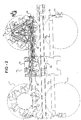
- Framing station 14 includes a first framing station assembly 50 positioned on one side of the assembly line 10 and a second framing station assembly 52 positioned on the opposite side of the assembly line 10 and constituting a mirror image of framing station assembly 50.
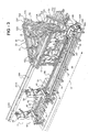
- framing station assembly 50 includes a base structure 54 and a pair of axially spaced pillars 56, 58 mounted on tracks 60 and moved by a motor mechanism 62, in unison, between a retracted outboard position to facilitate loading of the framing gates and an inboard position, seen in Figure 3, proximate the assembly line 10 where framing gates carried by the pillars can clampingly engage a loosely preassembled body 12 prior to the welding operation.
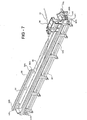
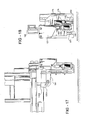
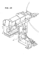
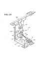
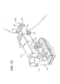
- Bearings 152 can be of the "caterpillar" type capable of crawling along the rounbar guide rail 72j and capable of jumping the gap between the roundbar guide rail 72j and the roundbar guide rail 96 of the associated linear track structure as the gate is moved along the track structure by the trolley.
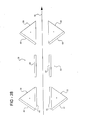
- Bearings 152 can, for example, be of the type shown in Figures 24, 25 and 26, available from Thompson Industries, Inc., as part number RW-1WA.
- Gate 42 further includes finger members 156 projecting downwardly at the rear face of the gate in rearwardly spaced relation to the main body structure 42a of the gate. Fingers 156 facilitate the engagement of the gate with the pillars 56, 58 after arrival of the gate at the framing station in a manner more fully described in U.S.
- the front caterpillar bearing 152 loses contact with rail 96 but the gate continues to be firmly guided during this brief transition time by the continued engagement of the trailing caterpillar bearing 152 on the roundbar 96, by the firm guidance of the overhead rollers 150 in the overhead tracks 200, and by the firm guidance of the lower edge of the trolley with the guide rail 92, the roundbar 96, and the horizontal rail 94 proximate the roundbar 96.
Landscapes
- Engineering & Computer Science (AREA)
- Mechanical Engineering (AREA)
- Physics & Mathematics (AREA)
- Optics & Photonics (AREA)
- Manufacturing & Machinery (AREA)
- Chemical & Material Sciences (AREA)
- Combustion & Propulsion (AREA)
- Transportation (AREA)
- Automobile Manufacture Line, Endless Track Vehicle, Trailer (AREA)
- Body Structure For Vehicles (AREA)
- Automatic Assembly (AREA)
Abstract
Description
According to the invention, the body framing system includes the framing station, a plurality of more than three pairs of opposed side framing gates for positioning at opposite sides of the framing station for use in welding a respective plurality of more than three vehicle body styles to allow the random production of the plurality of more than three vehicle body styles on the single assembly line, and a transfer apparatus assembly operative to randomly exchange any of the plurality of pairs of side framing gates positioned at the framing station with any other of the plurality of pairs of side framing gates within the predetermined build cycle time interval. This arrangement allows the random production interchange of the more than three vehicle body styles on the single assembly line while maintaining the predetermined build cycle time interval.
Claims (26)
- A body framing system for use with a vehicle assembly line in which loosely pre-assembled vehicle bodies are moved incrementally along a single assembly line from station to station, successive loosely pre-assembled vehicle bodies arrive at a framing station along the assembly line at predetermined build cycle time intervals, and each loosely pre-assembled vehicle body arriving at the framing station is welded to form a rigid vehicle body, the body framing system including:the framing station;a plurality of more than three pairs of opposed side framing gates for positioning at opposite sides of the framing station for use in welding a respective plurality of more than three vehicle body styles allowing random production of the plurality of more than three vehicle body styles on the single assembly line; anda transfer apparatus assembly operative for randomly exchanging any of the plurality of pairs of side framing gates positioned at the framing station with any other of the plurality of pairs of side framing gates within the predetermined build cycle time interval to allow the random production interchange of the more than three vehicle body styles on the single assembly line while maintaining the predetermined build cycle time interval.
- The body framing system of claim 1, wherein the transfer apparatus assembly includes a rotary transfer apparatus coacting with a linear transfer apparatus.
- The body framing system of claim 2, wherein the rotary transfer apparatus delivers framing gates to the linear transfer apparatus for delivery to the framing station.
- The body framing system of claim 3, wherein the rotary transfer apparatus includes first and second carousels positioned on opposite sides of the assembly line upstream of the framing station and third and fourth carousels positioned on opposite sides of the production line downstream of the framing station.
- The body framing system of claim 4, wherein the linear transfer apparatus includes a first linear track system extending from the first carousel to a first side of the framing station, a second linear track structure extending from the second carousel to a second, opposite side of the framing station, a third linear track structure extending from the third carousel to the first side of the framing station, and a fourth linear track structure extending from the fourth carousel to the second side of the framing station.
- The body framing system of claim 5, wherein each carousel has a polygonal configuration including at least two sides, each side capable of receiving a framing gate.
- The body framing system of claim 6, wherein the plurality of more than three pairs of opposed side framing gates includes four pairs of framing gates, and each carousel has three sides, wherein with the first pair of framing gates positionable on opposite sides of the framing station, the second pair of framing gates positionable on respective first sides of the first and second carousels, the third pair of framing gates positionable on respective second sides of the first and second carousels, and the fourth pair of framing gates positionable on respective first sides of the third and fourth carousels, all of the pairs of framing gates capable of being randomly interchanged by at least one of linear gate movements along the linear track structures and a combination of rotary movements of the carousels and linear gate movements along the linear track structures.
- The body framing system of claim 5 further comprising:a base structure;a first pair of spaced pillars mounted on the base structure on the first side of the framing station; anda second pair of spaced pillars mounted on the base structure on the second side of the framing station, the first and second pairs of pillars moveable on the base structure between outboard positions spaced outwardly from the assembly line and inboard positions proximate the assembly line, the first pair of pillars in its outboard position linearly aligned with the first and third linear track structures, and the second pair of pillars in its outboard position linearly aligned with the second and fourth linear track structures, wherein the framing gates are deliverable to the respective pillar pairs along the respective linear track structures with the pillar pairs in the outboard positions, thereafter the pillar pairs movable to the inboard positions to position the framing gates proximate the assembly line for clampingly engaging loosely preassembled vehicle bodies preparatory to welding operations.
- A carousel for use in delivering framing gates to a framing station on a vehicle body assembly line, the carousel comprising:a base structure positioned proximate the assembly line and including a support surface and a central pivot shaft upstanding from the support surface;a carousel body supported on the support surface, mounted on the pivot shaft for rotary movement about the axis of the shaft, and defining a plurality of sides, each side adapted to receive a framing gate;means operative for generating an air cushion between the support surface and an underface of the carousel body to lift the carousel body off of the support surface; andmeans operative for applying a turning force to the lifted body to rotate the body about the central axis to bring successive sides of the body into a position proximate the assembly line.
- The carousel of claim 9, wherein the air cushion generating means further comprises a plurality of air bags positioned on the underface of the carousel body and each air bag including a plurality of apertures in confronting relation to the support surface allowing pressurized air delivered to the air bags to inflate the bags to raise the carousel body off of the support surface and air escaping from the air bags through the apertures to generate an air cushion between the air bags and the support surface.
- The carousel of claim 10, wherein the air bags are positioned in circumferentially spaced relation about the central axis of the pivot shaft.
- The carousel of claim 10 intended for use with a linear track structure having one end positioned proximate the framing station and a free end, and further comprising:each side of the carousel body including a carousel track structure for supporting a respective framing gate and configured to be aligned with the free end of the linear track structure as the respective side of the carousel body is moved into a position proximate the assembly line allowing the framing gate to be slid off the carousel track structure and onto the linear track structure for delivery to the framing station.
- A transfer apparatus for use in delivering framing gates to a framing station on a vehicle body assembly line, the transfer apparatus comprising:a linear track structure having one end positioned proximate the framing station and a free end;a carousel positioned proximate the assembly line, defining a plurality of sides each adapted to receive a framing gate, and mounted for rotation about a central axis to bring successive sides of the carousel into a position proximate the free end of the track structure and in linear alignment with the track structure; anda transfer device operative to move a gate positioned on a side of the carousel in alignment with the track structure from the carousel side, onto the track structure, and along the track structure to the framing station.
- The transfer apparatus of claim 13 further comprising a trolley operative to engage a gate and move the gate along the track structure to the framing station.
- The transfer apparatus of claim 14, wherein each side of the carousel includes a carousel track structure for supporting a framing gate positioned on the respective side of the carousel and configured to be aligned with the free end of the linear track structure as the respective side of the carousel is moved into a position proximate the free end of the linear track structure.
- The transfer apparatus of claim 15 further comprising:a first latch device for latching a framing gate to a respective side of the carousel;a base structure supporting the carousel;a second latch device for latching the carousel to the base structure; anda latch control device operative in response to arrival of a carousel side at a position proximate the free end of the linear track structure to actuate the second latch device to latch the carousel to the base structure and release the first latch device to release the framing gate from the carousel and allow the trolley to move the released framing gate along the linear track structure to the framing station.
- The transfer apparatus of claim 16 further comprising:a third latch device to latch the trolley to a framing gate, the third latch device actuated prior to release of the first latch device and following engagement of the second latch device, and wherein the first latch device is released following engagement of the third latch device to allow the trolley to move the released framing gate to the framing station.
- The transfer apparatus of claim 17 further comprising:the base structure defining a support surface;cushion means operative to generate an air cushion between the support surface and an underface of the carousel to lift the carousel off of the support surface; andturning means operative to apply a turning force to the lifted carousel to rotate the carousel about the central axis to bring successive sides of the carousel into position proximate the free end of the track structure and in linear alignment with the track structure.
- The transfer apparatus of claim 18, wherein the second latch device is released following actuation of the cushion means, thereafter the turning means is actuated to bring a respective side of the carousel carrying a respective framing gate into alignment with the linear track structure, thereafter the second linear latch device is actuated to latch the carousel to the base structure, thereafter the third latch device is actuated to latch the trolley to the respective framing gate, thereafter the first latch device is released to release the respective framing gate from the carousel, and thereafter the trolley is actuated to move the respective framing gate to the framing station.
- The transfer apparatus of claim 19, wherein the cushion means is deactivated to lower the carousel back down to the support surface prior to actuation of the trolley to move the respective framing gate to the framing station.
- A method of moving pairs of framing gates to a framing station on a motor vehicle assembly line where loosely preassembled vehicle bodies are clamped by the framing gate pairs while the bodies are welded to form a rigid vehicle body, the method comprising the steps of:providing a pair of carousels each having a plurality of substantially flat sides;positioning the carousels along and on opposite sides of the assembly line in spaced relation to the framing station;mounting the carousels for rotation to bring successive sides of the carousel into a discharge position proximate and substantially parallel to the assembly line;positioning a pair of framing gates on one side of the respective pair of carousels;rotating the carousels to bring the one carousel sides into the discharge position;discharging the framing gates from the carousels; andsliding the framing gates along the assembly line to opposite sides of the framing station.
- The method of claim 21 further comprising the step of:providing linear track structures extending from each carousel to the framing station; andwherein the sliding step of the discharged framing gates along the assembly line to the framing station includes sliding the discharged framing gates along the linear track structures to the framing station.
- The method of claim 21, wherein the rotating step of the carousels further comprises:generating an air cushion between an underface of the carousels and a support surface to lift the carousels off of the support surface; andthereafter applying a turning force to the lifted carousels.
- The method of claim 21, wherein the pair of carousels includes a first pair of carousels positioned upstream on the assembly line from the framing station, and the pair of framing gates includes a first pair of framing gates, and wherein the sliding step of the discharged framing gates along the assembly line to opposite sides of the framing station includes sliding the framing gates downstream to the framing station, and further comprising the steps of:providing a second pair of carousels each having a plurality of substantially flat sides;positioning the second pair of carousels along and on opposite sides on the assembly line downstream of the framing station;mounting the second pair of carousels for rotation to bring successive sides of the second pair of carousels into a discharge position proximate and substantially parallel to the assembly line;positioning a second pair of framing gates on one side of the respective second pair of carousels;rotating the second pair of carousels to bring the one sides of the second pair of carousels into the discharge position;discharging the second pair of framing gates from the second pair of carousels; andsliding the discharged second pair of framing gates upstream to the framing station.
- The method of claim 24 further comprising the steps of:providing a third pair of framing gates;positioning the third pair of framing gates on a second side of one of said first and second pairs of carousel; anddischarging the third pair of framing gates from the second side of the respective carousels for delivery to the framing station.
- The method of claim 25 further comprising the steps of:providing a fourth pair of framing gates;positioning the fourth pair of framing gates on opposite sides of the framing station;randomly interchanging the pair of framing gates positioned at the framing station by selective rotation of the carousels; andselective sliding movement of the framing gates between the framing station and the carousels.
Applications Claiming Priority (2)
| Application Number | Priority Date | Filing Date | Title |
|---|---|---|---|
| US37089102P | 2002-04-08 | 2002-04-08 | |
| US370891P | 2002-04-08 |
Publications (2)
| Publication Number | Publication Date |
|---|---|
| EP1352818A2 true EP1352818A2 (en) | 2003-10-15 |
| EP1352818A3 EP1352818A3 (en) | 2006-09-06 |
Family
ID=28454869
Family Applications (1)
| Application Number | Title | Priority Date | Filing Date |
|---|---|---|---|
| EP03252173A Withdrawn EP1352818A3 (en) | 2002-04-08 | 2003-04-05 | Vehicle framing system for plurality of vehicle body styles |
Country Status (3)
| Country | Link |
|---|---|
| US (3) | US6932263B2 (en) |
| EP (1) | EP1352818A3 (en) |
| CA (1) | CA2424448C (en) |
Cited By (7)
| Publication number | Priority date | Publication date | Assignee | Title |
|---|---|---|---|---|
| WO2006094631A1 (en) * | 2005-03-09 | 2006-09-14 | Kuka Schweissanlagen Gmbh | Changeover device for tenter frames |
| GB2427175A (en) * | 2005-06-16 | 2006-12-20 | Ford Global Tech Llc | Assembly method for a vehicle |
| CN103386542A (en) * | 2013-07-05 | 2013-11-13 | 深圳先进技术研究院 | Automatic welding device |
| WO2015128342A1 (en) * | 2014-02-25 | 2015-09-03 | Kuka Systems Gmbh | Interchanging apparatus and interchanging method for clamping frames supporting vehicle body parts between a clamping frame transport device and a frame conveyor by means of clamping frame magazines |
| CN108025779A (en) * | 2015-07-03 | 2018-05-11 | 库卡系统有限责任公司 | Expect storehouse, process units and method |
| WO2018091452A1 (en) * | 2016-11-15 | 2018-05-24 | Tms Turnkey Manufacturing Solutions Gmbh | Joining plant comprising a joining station and clamping frames |
| CN113385844A (en) * | 2021-06-04 | 2021-09-14 | 东风柳州汽车有限公司 | Welding method of automobile side wall assembly |
Families Citing this family (59)
| Publication number | Priority date | Publication date | Assignee | Title |
|---|---|---|---|---|
| DE20211755U1 (en) * | 2002-07-30 | 2003-12-18 | Kuka Schweissanlagen Gmbh | processing plant |
| JP4350441B2 (en) * | 2003-07-04 | 2009-10-21 | 本田技研工業株式会社 | Component transportation / mounting method and apparatus |
| ATE344117T1 (en) * | 2004-06-08 | 2006-11-15 | Comau Spa | DEVICE FOR WELDING VEHICLE BODIES |
| DE202005001780U1 (en) * | 2005-02-03 | 2006-06-08 | Kuka Schweissanlagen Gmbh | Manufacturing facility for components |
| US20060218767A1 (en) * | 2005-04-05 | 2006-10-05 | Progressive Tool & Industries, Co. | Framing apparatus for car body welding station |
| US7896217B2 (en) * | 2005-04-27 | 2011-03-01 | Comau, Inc. | Welding station framing apparatus with breakaway provision |
| EP1897653B1 (en) * | 2006-09-07 | 2009-01-07 | COMAU SpA | System for welding motor-vehicle bodies |
| US8042249B2 (en) | 2006-10-04 | 2011-10-25 | Camau, Inc. | Motor vehicle body assembly apparatus |
| US7677428B2 (en) * | 2006-11-20 | 2010-03-16 | Comau, Inc. | Motor vehicle body framing apparatus |
| DE202007002364U1 (en) * | 2007-02-14 | 2008-06-19 | Kuka Systems Gmbh | positioning |
| JP4448875B2 (en) * | 2007-09-26 | 2010-04-14 | 本田技研工業株式会社 | Welding equipment |
| US8201723B2 (en) * | 2008-03-12 | 2012-06-19 | Comau, Inc. | Robotic high density welding body shop |
| KR100865795B1 (en) * | 2008-03-26 | 2008-10-29 | (주)우신시스템 | Body welding device with independent movable carrier |
| KR20090105759A (en) | 2008-04-03 | 2009-10-07 | 현대자동차주식회사 | Automotive floor production system |
| DE102008020083A1 (en) * | 2008-04-22 | 2009-10-29 | Dr. Ing. H.C. F. Porsche Aktiengesellschaft | Method for manufacturing motor vehicles |
| US8713780B2 (en) | 2008-05-13 | 2014-05-06 | Comau, Inc. | High density welding subassembly machine |
| US8274009B2 (en) * | 2009-07-14 | 2012-09-25 | Easom Automation Systems, Inc. | Automotive body shop flexible framing gate changing system |
| US8210418B1 (en) * | 2011-06-09 | 2012-07-03 | Landoll Corporation | Multi-station, gantry-based automated welding system |
| US8434657B2 (en) | 2011-06-09 | 2013-05-07 | Landoll Corporation | Gantry-based welding system and method |
| PL2554459T3 (en) * | 2011-08-01 | 2017-07-31 | Comau Spa | System for assembling a component on a body structure of a motor-vehicle |
| CN102873477B (en) * | 2012-03-13 | 2015-05-13 | 浙江金刚汽车有限公司 | Automobile model switching mechanism of automobile production line |
| CN102699585B (en) * | 2012-05-25 | 2014-12-03 | 长城汽车股份有限公司 | Flexible welding production line for side wall plate of automobile |
| CN103128469B (en) * | 2013-02-28 | 2015-11-11 | 长城汽车股份有限公司 | System and method for splicing side body and lower part of vehicle body |
| CN103302426B (en) * | 2013-06-17 | 2015-04-22 | 四川成焊宝玛焊接装备工程有限公司 | System for automatically changing multi-vehicle type car body positioning fixtures for flexible welding of robot |
| DE102013016827B4 (en) | 2013-10-10 | 2019-05-29 | Daimler Ag | Production system and method for producing different variants of crude modules |
| CN104551491A (en) * | 2014-11-14 | 2015-04-29 | 合肥常青机械股份有限公司 | Novel beam assembly welding fixture |
| CN104551493A (en) * | 2014-11-14 | 2015-04-29 | 合肥常青机械股份有限公司 | Welding fixture for circular tubular beam assembly of mini truck frame |
| CA3008600C (en) | 2014-12-15 | 2022-09-13 | Comau Llc | Modular vehicle assembly system and method |
| CN104511704B (en) * | 2014-12-15 | 2016-03-30 | 张家港江苏科技大学产业技术研究院 | A kind of flexibility Combination Welding streamline |
| CN104843446B (en) * | 2015-05-29 | 2016-08-24 | 广州瑞松北斗汽车装备有限公司 | A kind of carrying based on multi-vehicle-type is equipped |
| CN104960918B (en) * | 2015-05-29 | 2016-09-07 | 广州瑞松北斗汽车装备有限公司 | It is adapted to the tray mechanism of multi-vehicle-type carrying equipment |
| BR112018006726B1 (en) | 2015-10-27 | 2022-08-23 | Comau S.P.A | SYSTEM AND CORRESPONDING PROCESS FOR GLUING TOGETHER TWO COMPONENTS IN A VEHICLE BODY ASSEMBLY LINE |
| CA3018159C (en) | 2016-03-24 | 2023-10-17 | Masonite Corporation | Wood door slab processing system, and related methods |
| US10384873B2 (en) | 2016-05-06 | 2019-08-20 | Comau Llc | Inverted carrier lift device system and method |
| CN106624504A (en) * | 2017-02-27 | 2017-05-10 | 武汉瑞松北斗汽车装备有限公司 | Power and free chain feeding system of automobile cabin assembly flexible automatic production line |
| CN106984936B (en) * | 2017-05-20 | 2023-07-28 | 上汽通用五菱汽车股份有限公司 | Tail door frame positioning fixture with welding function |
| CN107263010A (en) * | 2017-08-08 | 2017-10-20 | 柳州市开宇机器人有限公司 | A kind of device for lifting clamping efficiency |
| CN107585225B (en) * | 2017-09-25 | 2023-05-12 | 郑州日产汽车有限公司 | Bearing and non-bearing type vehicle body and vehicle type mixed flow assembly production line |
| PL3707096T3 (en) | 2017-11-07 | 2024-09-23 | Comau Llc | Transport system and methods |
| CN108482522B (en) * | 2018-03-23 | 2024-01-02 | 郑州多元智能装备股份有限公司 | Numerical control combined tyre for all-aluminum vehicle body |
| CN110421303B (en) * | 2019-09-05 | 2020-06-05 | 重庆大学 | Flexible clamp for automobile door welding and rotary switching type flexible clamping clamp body |
| US11420853B2 (en) | 2019-10-03 | 2022-08-23 | Comau Llc | Assembly material logistics system and methods |
| CN110625014B (en) * | 2019-11-08 | 2025-03-21 | 西南交通大学 | A quick die change system for FET1200 skin forming machine |
| CN111185713B (en) * | 2020-03-17 | 2022-02-22 | 上海斯瑞佛汽车零部件有限公司 | Automobile pipe fitting positioning tool |
| CN111438455B (en) * | 2020-04-24 | 2021-11-12 | 中车青岛四方机车车辆股份有限公司 | Car body spot welding production line layout structure and automatic production line system |
| CN111408883B (en) * | 2020-04-28 | 2024-08-13 | 浙江大地钢结构有限公司 | Adjustable positioning support for welding special-shaped nodes of steel members |
| SE545823C2 (en) * | 2020-04-30 | 2024-02-13 | Lamiflex Group Ab | Robot Tool, Robot System and Method for Coil Packaging |
| PL4161851T3 (en) | 2020-06-08 | 2025-12-08 | Comau Llc | Assembly material logistics system and methods |
| DE102020116123B4 (en) * | 2020-06-18 | 2025-01-02 | Dr. Ing. H.C. F. Porsche Aktiengesellschaft | Production station for workpieces, especially body parts, as well as production plant |
| CN112589345B (en) * | 2020-12-02 | 2022-12-30 | 无锡曙光模具有限公司 | Electric cabinet top cover welding tool and welding process method thereof |
| CN113428261A (en) * | 2021-07-29 | 2021-09-24 | 重庆众思创智能科技有限公司 | Locking positioning mechanism is used in production of multi-vehicle type mixed flow |
| CN113830205B (en) * | 2021-09-02 | 2025-05-06 | 赛亚森汽车系统(上海)有限公司 | Automobile cockpit module turnover system |
| CN113798757B (en) * | 2021-09-17 | 2023-09-08 | 安徽科汇钢结构工程有限公司 | Lattice column part machining device |
| CN114378513B (en) * | 2021-12-29 | 2022-07-26 | 盐城东方天成机械有限公司 | Steel construction sideboard self-adaptation welding position device |
| CN114161067B (en) * | 2022-01-06 | 2024-03-26 | 中车唐山机车车辆有限公司 | Roof assembly welding tool |
| CN117020545B (en) * | 2023-10-08 | 2023-12-12 | 福建荣耀健康科技股份有限公司 | Massage armchair part welding jig |
| CN117697296B (en) * | 2024-01-08 | 2024-05-14 | 湖北和亿方装配式建筑科技有限公司 | Automatic fixture for welding and processing prefabricated building components |
| CN117733463B (en) * | 2024-01-22 | 2024-05-14 | 蒙阴五月树液压机械有限公司 | Track beam welding tooling |
| CN117884834B (en) * | 2024-03-14 | 2024-05-07 | 淄博齐森电力设备有限公司 | Electric control cabinet preparation system |
Family Cites Families (48)
| Publication number | Priority date | Publication date | Assignee | Title |
|---|---|---|---|---|
| US4162387A (en) | 1977-03-14 | 1979-07-24 | Ettore De Candia | Car body welding assembly system |
| US4442335A (en) | 1982-03-31 | 1984-04-10 | Comau S.P.A. | Side aperture welding assembly system |
| US4494687A (en) | 1983-03-21 | 1985-01-22 | Comau S.P.A. | Expanded car body welding assembly system |
| DE3414387C2 (en) * | 1984-04-16 | 1986-03-06 | Kuka Schweissanlagen + Roboter Gmbh, 8900 Augsburg | Device for automatically conveying stenter frames or the like, especially in transfer lines |
| JPS6112474A (en) * | 1984-06-26 | 1986-01-20 | Toyota Motor Corp | Vehicle body assembling device |
| JPS61125748A (en) * | 1984-11-22 | 1986-06-13 | Mazda Motor Corp | Composite working device with robot |
| DE3443076A1 (en) * | 1984-11-26 | 1986-06-05 | Kuka Schweissanlagen + Roboter Gmbh, 8900 Augsburg | FLEXIBLE MANUFACTURING SYSTEM FOR THE MACHINING AND PRODUCTION OF MULTI-PIECE ASSEMBLIES, IN PARTICULAR RAW BODY ASSEMBLIES |
| DE3506314A1 (en) * | 1985-02-22 | 1986-08-28 | Kuka Schweissanlagen + Roboter Gmbh, 8900 Augsburg | METHOD AND DEVICE FOR AUTOMATIC JOINTING AND EDITING |
| IT1183763B (en) | 1985-02-28 | 1987-10-22 | Comau Spa | IMPROVEMENTS FOR WELDING SYSTEMS OF BODYWORKS OF MOTOR VEHICLES |
| JPS61284379A (en) * | 1985-06-06 | 1986-12-15 | 本田技研工業株式会社 | Robot device |
| US4776085A (en) | 1985-11-08 | 1988-10-11 | Honda Giken Kogyo Kabushiki Kaisha | Apparatus for use in automobile assembling |
| GB2204840B (en) * | 1987-05-21 | 1992-01-22 | Honda Motor Co Ltd | Automatic wheel attachment apparatus |
| GB2206316B (en) | 1987-03-28 | 1991-03-20 | Lamb Technicon Uk Operations C | Holding apparatus for a vehicle assembly line |
| MX163623B (en) | 1987-04-17 | 1992-06-08 | Honda Motor Co Ltd | METHOD FOR ASSEMBLING A VEHICLE BODY FROM A TWO-WHEEL VEHICLE AND AN ASSEMBLY DEVICE FOR THE SAME |
| DE3720175A1 (en) * | 1987-06-16 | 1988-12-29 | Kuka Schweissanlagen & Roboter | DEVICE FOR AUTOMATICALLY CONVEYING TENSIONER FRAME OR THE LIKE IN TRANSFER ROADS |
| EP0335124B1 (en) * | 1988-03-31 | 1992-08-19 | KUKA Schweissanlagen GmbH | Automatic assembling device for joining sub-assemblies to a motor car body from underneath |
| IT1226104B (en) * | 1988-07-07 | 1990-12-10 | Fata Europ Group | IMPROVED SYSTEM EQUIPPED WITH ROTARY GROUPS OF EQUIPMENT FOR WELDING VEHICLE BODIES IN A SINGLE WORKING STATION. |
| IT1223690B (en) | 1988-07-13 | 1990-09-29 | Comau Spa | DEVICE FOR THE WELDING OF MOTOR VEHICLE BODIES |
| US5011068A (en) | 1989-12-05 | 1991-04-30 | Progressive Tool & Industries Co. | Automotive body framing system |
| US5037022A (en) | 1990-01-05 | 1991-08-06 | Chrysler Corporation | Vehicle body welding assembly system |
| US4991707A (en) | 1990-01-12 | 1991-02-12 | Progressive Tool & Industries Co. | Bodyside panel handling conveyor |
| IT224002Z2 (en) | 1990-01-31 | 1995-10-05 | Comau Spa | DEVICE FOR THE WELDING OF MOTOR VEHICLE BODIES |
| JP2895906B2 (en) * | 1990-03-31 | 1999-05-31 | マツダ株式会社 | Auto body assembly equipment |
| IT1248419B (en) * | 1990-06-15 | 1995-01-16 | Comau Spa | ASSEMBLY STATION OF A PRINTED SHEET STRUCTURE PROVIDED WITH A WELDING ROBOT THAT CAN ALSO BE USED FOR THE PERIODIC CONTROL OF THE EQUIPMENT USED IN THE STATION. |
| JP2504327B2 (en) | 1990-11-22 | 1996-06-05 | 三菱自動車工業株式会社 | Articulated welding robot and electrode centering method in the robot |
| CA2054856C (en) | 1990-11-28 | 1994-12-13 | Akio Hamada | System for assembling motorcar vehicle body |
| US5374799A (en) * | 1991-01-30 | 1994-12-20 | Mazda Motor Corporation | Method for the assembly of automotive vehicle bodies and a jig unit therefor |
| US5141093A (en) | 1991-04-17 | 1992-08-25 | Progressive Tool & Industries Co. | Automotive body panel handling apparatus |
| GB9109332D0 (en) * | 1991-05-01 | 1991-06-26 | Pigott Norman B | Workstation |
| DE9105490U1 (en) * | 1991-05-03 | 1992-09-10 | KUKA Schweissanlagen GmbH, 86165 Augsburg | Processing station for workpieces, especially vehicle bodies in a transfer line |
| IT1249980B (en) * | 1991-08-07 | 1995-03-30 | Comau Spa | DEVICE FOR THE WELDING OF STRUCTURES, SUCH AS BODIES OF MOTOR VEHICLES OR PARTS OF THEM, MADE UP OF ELEMENTS OF PRINTED SHEET METAL ASSEMBLED PRELIMINARILY AMONG THEM IN A LABULAR WAY. |
| US5265317A (en) * | 1991-12-19 | 1993-11-30 | Progressive Tool & Industries Co. | Geometry station |
| DE9209686U1 (en) * | 1992-07-15 | 1992-09-10 | KUKA Schweissanlagen GmbH, 86165 Augsburg | Processing station for vehicle bodies in a transfer line |
| IT227649Y1 (en) * | 1992-09-30 | 1997-12-15 | Comau Spa | DEVICE FOR THE QUICK CHANGE OF WORKPIECE PALLET IN AN ASSEMBLY MACHINE. |
| US5409158A (en) * | 1993-07-08 | 1995-04-25 | Progressive Tool & Industries Company | Automobile framing system |
| IT1261262B (en) * | 1993-09-15 | 1996-05-09 | Comau Spa | POINT WELDING DEVICE FOR STRUCTURES CONSISTING OF PRINTED SHEET ELEMENTS |
| IT1261269B (en) * | 1993-09-20 | 1996-05-09 | Comau Spa | POINT WELDING DEVICE FOR STRUCTURES CONSISTING OF PRINTED SHEET ELEMENTS, IN PARTICULAR MOTOR VEHICLE BODIES |
| US5427300A (en) | 1994-03-22 | 1995-06-27 | Progressive Tool & Industries Co. | Apparatus for framing vehicle bodies |
| US5560535A (en) * | 1995-03-30 | 1996-10-01 | Western Atlas, Inc. | Flexible body framing system |
| GB2304649B (en) * | 1995-09-07 | 1999-12-01 | Western Atlas Uk Ltd | Improved gate change facility |
| DE19806963A1 (en) * | 1997-03-22 | 1998-10-08 | Thyssen Industrie | Feed, clamping and welding system for car-body components |
| EP0927598A1 (en) * | 1997-12-18 | 1999-07-07 | COMAU S.p.A. | Device for spot-welding of motor-vehicle bodies or sub-assemblies thereof |
| DE59900465D1 (en) * | 1998-01-24 | 2002-01-10 | Kuka Schweissanlagen Gmbh | FLOORING DEVICE WITH PRESSING AND TENSIONING ELEMENTS |
| DE29806823U1 (en) * | 1998-04-16 | 1999-09-09 | KUKA Schweissanlagen GmbH, 86165 Augsburg | Device for handling at least one clamping frame, in particular for the assembly of vehicle body shells |
| DE29813669U1 (en) * | 1998-07-31 | 1999-12-23 | KUKA Schweissanlagen GmbH, 86165 Augsburg | Flexible work station |
| US6173881B1 (en) * | 1998-11-11 | 2001-01-16 | Progressive Tool & Industries Company | Car body assembly and welding station with reciprocal gate-supporting system |
| WO2001000370A1 (en) * | 1999-06-26 | 2001-01-04 | Kuka Schweissanlagen Gmbh | Method and device for calibrating robot measuring stations, manipulators and associated optical measuring devices |
| JP2001040536A (en) * | 1999-07-23 | 2001-02-13 | Teijin Seiki Co Ltd | Method and apparatus for relaxing heat treatment of yarn |
-
2003
- 2003-03-28 US US10/401,471 patent/US6932263B2/en not_active Expired - Lifetime
- 2003-04-04 CA CA002424448A patent/CA2424448C/en not_active Expired - Fee Related
- 2003-04-05 EP EP03252173A patent/EP1352818A3/en not_active Withdrawn
-
2005
- 2005-06-23 US US11/165,475 patent/US7510109B2/en not_active Expired - Lifetime
-
2008
- 2008-05-28 US US12/127,956 patent/US20080295335A1/en not_active Abandoned
Cited By (13)
| Publication number | Priority date | Publication date | Assignee | Title |
|---|---|---|---|---|
| WO2006094631A1 (en) * | 2005-03-09 | 2006-09-14 | Kuka Schweissanlagen Gmbh | Changeover device for tenter frames |
| US8365396B2 (en) | 2005-03-09 | 2013-02-05 | Kuka Systems Gmbh | Changeover device for clamping frames |
| GB2427175A (en) * | 2005-06-16 | 2006-12-20 | Ford Global Tech Llc | Assembly method for a vehicle |
| GB2427175B (en) * | 2005-06-16 | 2009-01-21 | Ford Global Tech Llc | An assembly method for a vehicle |
| DE102006027223B4 (en) * | 2005-06-16 | 2016-03-31 | Ford Global Technologies, Llc | Method for producing an assembly |
| CN103386542B (en) * | 2013-07-05 | 2016-03-23 | 深圳先进技术研究院 | Automatic welding device |
| CN103386542A (en) * | 2013-07-05 | 2013-11-13 | 深圳先进技术研究院 | Automatic welding device |
| WO2015128342A1 (en) * | 2014-02-25 | 2015-09-03 | Kuka Systems Gmbh | Interchanging apparatus and interchanging method for clamping frames supporting vehicle body parts between a clamping frame transport device and a frame conveyor by means of clamping frame magazines |
| US10272962B2 (en) | 2014-02-25 | 2019-04-30 | Kuka Systems Gmbh | Changing apparatus and changing method for clamping frames supporting vehicle body parts between a clamping frame transport device and a frame conveyor by means of clamping frame magazines |
| CN108025779A (en) * | 2015-07-03 | 2018-05-11 | 库卡系统有限责任公司 | Expect storehouse, process units and method |
| WO2018091452A1 (en) * | 2016-11-15 | 2018-05-24 | Tms Turnkey Manufacturing Solutions Gmbh | Joining plant comprising a joining station and clamping frames |
| WO2018091450A1 (en) * | 2016-11-15 | 2018-05-24 | Tms Turnkey Manufacturing Solutions Gmbh | Joining plant comprising a joining station and clamping frames |
| CN113385844A (en) * | 2021-06-04 | 2021-09-14 | 东风柳州汽车有限公司 | Welding method of automobile side wall assembly |
Also Published As
| Publication number | Publication date |
|---|---|
| US6932263B2 (en) | 2005-08-23 |
| US20080295335A1 (en) | 2008-12-04 |
| EP1352818A3 (en) | 2006-09-06 |
| US20030189085A1 (en) | 2003-10-09 |
| US20050236461A1 (en) | 2005-10-27 |
| CA2424448C (en) | 2009-07-21 |
| CA2424448A1 (en) | 2003-10-08 |
| US7510109B2 (en) | 2009-03-31 |
Similar Documents
| Publication | Publication Date | Title |
|---|---|---|
| CA2424448C (en) | Vehicle framing system for plurality of vehicle body styles | |
| CA2031698C (en) | Bodyside panel handling conveyor | |
| CN100560287C (en) | Conveying operation method and device thereof | |
| CA2066301C (en) | Automotive body panel handling apparatus | |
| EP2377642A1 (en) | Welding apparatus and method of welding using the apparatus | |
| US5177862A (en) | Automatic assembly system | |
| JPH0422747B2 (en) | ||
| CN1706587B (en) | System for welding motor vehicles bodies | |
| US20070041819A1 (en) | Workpiece feeding apparatus | |
| US6173881B1 (en) | Car body assembly and welding station with reciprocal gate-supporting system | |
| WO2010038629A1 (en) | Carrier apparatus for drive-train component part assembly and vehicle assembly method | |
| US5697752A (en) | Overhead transfer clamp actuator and linkage | |
| JP2002274451A (en) | Body assembly equipment | |
| US5395205A (en) | Part loading apparatus having harmonically driven shuttle and pivotal part supporting frame | |
| EP1837120A1 (en) | Welding station for motor-vehicle bodies or sub-assemblies thereof comprising bottom liftable and side movable frames interconnected with cams | |
| CN115338555A (en) | Automatic welding machine device and welding method for seat framework | |
| CN213672351U (en) | Automatic welding device for civil air defense door frame | |
| CN214455036U (en) | Coating film turning device | |
| JP2000042657A (en) | Hemming work manufacturing equipment | |
| JPH06239223A (en) | Movable fence for platform | |
| CN112777322A (en) | Coating film turning device | |
| JPH04201131A (en) | Inclinination device for work on conveyance line for work | |
| WO1999024215A1 (en) | Car body assembly and welding station with reciprocal gate-supporting system | |
| JPS62110579A (en) | Car assembly device | |
| JP3904478B2 (en) | Wire gripping device in a transfer vehicle |
Legal Events
| Date | Code | Title | Description |
|---|---|---|---|
| PUAI | Public reference made under article 153(3) epc to a published international application that has entered the european phase |
Free format text: ORIGINAL CODE: 0009012 |
|
| AK | Designated contracting states |
Kind code of ref document: A2 Designated state(s): AT BE BG CH CY CZ DE DK EE ES FI FR GB GR HU IE IT LI LU MC NL PT RO SE SI SK TR |
|
| AX | Request for extension of the european patent |
Extension state: AL LT LV MK |
|
| PUAL | Search report despatched |
Free format text: ORIGINAL CODE: 0009013 |
|
| AK | Designated contracting states |
Kind code of ref document: A3 Designated state(s): AT BE BG CH CY CZ DE DK EE ES FI FR GB GR HU IE IT LI LU MC NL PT RO SE SI SK TR |
|
| AX | Request for extension of the european patent |
Extension state: AL LT LV MK |
|
| AKX | Designation fees paid | ||
| REG | Reference to a national code |
Ref country code: DE Ref legal event code: 8566 |
|
| STAA | Information on the status of an ep patent application or granted ep patent |
Free format text: STATUS: THE APPLICATION IS DEEMED TO BE WITHDRAWN |
|
| 18D | Application deemed to be withdrawn |
Effective date: 20070307 |