CN214455036U - Coating film turning device - Google Patents
Coating film turning device Download PDFInfo
- Publication number
- CN214455036U CN214455036U CN202120281053.0U CN202120281053U CN214455036U CN 214455036 U CN214455036 U CN 214455036U CN 202120281053 U CN202120281053 U CN 202120281053U CN 214455036 U CN214455036 U CN 214455036U
- Authority
- CN
- China
- Prior art keywords
- conveying
- turnover
- frame
- fixed
- conveying mechanism
- Prior art date
- Legal status (The legal status is an assumption and is not a legal conclusion. Google has not performed a legal analysis and makes no representation as to the accuracy of the status listed.)
- Active
Links
Images


Abstract
The utility model relates to a coating film turning device, including jacking rotary mechanism, rotatable walking track, conveying mechanism, transport frock and tilting mechanism, jacking rotary mechanism and the cooperation equipment of rotatable walking track, conveying mechanism install in jacking rotary mechanism's bottom below, the transport frock fix in one side of conveying mechanism, tilting mechanism is fixed through upset arm and conveying mechanism, realizes the conveying mechanism upset. By adopting the film coating turnover device of the utility model, two inlets of the film coating machine can be butted through the moving function of the walking mechanism; the rotating function of the traveling mechanism ensures that the orientation of the glass coating surface is aligned to the correct coating direction when the glass coating surface is coated inside the coating machine; the jacking rotating mechanism is matched with other functional machines to realize the taking and placing of the glass, and the automatic feeding and discharging of the glass into and out of the film coating machine are completed through the conveying mechanism; the glass is positioned and fixed by utilizing the conveying tool, so that the function of automatically finishing the film coating of the ultrathin luminous glass is realized conveniently.
Description
Technical Field
The utility model relates to an industrial production field especially relates to luminous glass coating film technology field, specifically indicates a coating film turning device.
Background
The luminous glass is used as a high and new technology product in the glass industry, related technologies are still researched and developed at present in the domestic aspect, the equipment is designed to solve the problems that the luminous glass is matched with other function machines to realize automatic positioning, automatic loading, automatic unloading and automatic loading and unloading before entering a film coating machine for film coating, the conventional method is completely manual treatment at present, but because the temperature in the film coating machine is close to 400 ℃, the glass which is just coated cannot be separated from a tooling plate immediately by manpower to carry out the next process, the glass needs to be operated after the temperature is reduced, a large amount of time is wasted in the waiting process, the production efficiency is reduced, the defect rate is increased due to the fact that manual operation is increased when the glass is damaged in the film loading and unloading processes, the environmental variable is not easy to control, and certain dangerousness exists in the operation environment of workers and the operation environment of the workers.
SUMMERY OF THE UTILITY MODEL
The utility model aims at overcoming the defects of the prior art and providing a coating turnover device which has the advantages of good freedom, high production efficiency and wide application range.
In order to realize the purpose, the coating turnover device of the utility model comprises the following components:
the film coating turnover device is mainly characterized by comprising a jacking rotating mechanism, a rotatable walking track, a conveying mechanism, a conveying tool and a turnover mechanism, wherein the jacking rotating mechanism and the rotatable walking track are assembled in a matched mode; the jacking rotating mechanism pushes the fixed support to lift through the servo electric cylinder, so as to lift the glass, and the glass is taken and placed by utilizing a clearance fit function machine between the ejector rods; the rotatable walking track realizes a device which is rotatably arranged on the rotary platform at any angle through the servo rotary platform, and the walking track frame is pushed by the power module to move the device along the track; the conveying mechanism finishes automatic film coating of glass in and out; the conveying tool fixes the glass.
Preferably, the jacking and rotating mechanism comprises a fixed support, a rotating platform, a lifting fixed plate, a guide post and a contact supporting rod, wherein the rotating platform is fixedly provided with a servo electric cylinder, the guide post on the servo electric cylinder is locked and fixed on one side of the lifting fixed plate by using a bolt, the fixed support is locked and fixed on the other side of the lifting fixed plate by using a bolt, and the contact supporting rod is locked on the fixed support by using a supporting rod seat.
Preferably, the rotatable track of walking include servo rotary platform, the track frame of walking, power module and the whole frame in track, servo rotary platform install the upper surface mounting panel at the track frame of walking, the power module install on the inside mounting panel of the whole frame in track, the output piece of power module is connected with the track frame of walking through floating joint through power output's connecting plate, the track frame of walking both sides have 2 sets of symmetrical sliders, the slide rail is installed on the whole frame in track.
Preferably, the conveying mechanism comprises a conveying mechanism frame, a servo power assembly, a magnetic wheel transmission assembly, an unpowered driven conveying assembly, a positioning cylinder and a pressing cylinder, the magnetic wheel transmission assembly is mounted on the inner surface of the bottom of the conveying mechanism frame, the servo power assembly drives the magnetic wheel transmission assembly through a bevel gear, the unpowered driven conveying assembly is mounted on the inner surface of the upper portion of the conveying mechanism frame, the positioning cylinder and the pressing cylinder are mounted on two sides of the conveying mechanism frame respectively, when the conveying mechanism positions the tool, the positioning cylinder extends out to block the conveying tool, and the pressing cylinder presses the tool through rotation.
Preferably, the conveying tool comprises a conveying tool frame, an automatic locking and positioning block, a clamping plate and a guide round rod, wherein the automatic locking and positioning block is arranged on the side surface of the front side of the conveying tool frame and is used for fixing the glass on the tool; the magnetic wheel transmission assembly of the conveying mechanism matched with the conveying tool frame realizes positioning by utilizing the dead weight of the conveying tool.
Preferably, the turnover mechanism comprises a turnover power assembly, a swing arm, a fixed limiting assembly, a turnover shaft and a turnover arm, wherein the swing arm is connected with the turnover shaft through a tensioning sleeve, two sides of the turnover shaft are fixed through bearings, the fixed limiting assembly is arranged at the central part of the turnover shaft through the tensioning sleeve, the turnover arm is respectively arranged at two ends of the rotating shaft through the tensioning sleeve, and the turnover arm and the conveying mechanism are fixed through bolts; the turnover power assembly is composed of a swing electric cylinder, the turnover mechanism uses the turnover power assembly as rotary power to push the swing arm, and the swing electric cylinder pushes the swing arm to drive the rotary shaft to rotate so as to realize turnover of the conveying mechanism.
By adopting the film coating turnover device of the utility model, two inlets of the film coating machine can be butted through the moving function of the walking mechanism; the rotating function of the traveling mechanism ensures that the orientation of the glass coating surface is aligned to the correct coating direction when the glass coating surface is coated inside the coating machine; the glass taking and placing machine is realized by matching the jacking rotating mechanism with other functional machines (robots or other special machine for taking and placing the glass), and the automatic glass feeding and discharging of the coating machine are completed by the conveying mechanism; the glass is fixed in position by utilizing the conveying tool, so that convenience is realized. The components are matched with each other to work, so that the function of automatically finishing film coating of the ultrathin luminous glass is realized.
Drawings
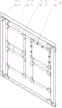
Fig. 1 is a perspective view of a jacking and rotating mechanism of the film coating and turning device of the present invention.
Fig. 2 is a perspective view of the rotatable walking track of the film coating turnover device of the present invention.
Fig. 3 is a perspective view of the conveying mechanism of the film coating turnover device of the present invention.
Fig. 4 is a perspective view of the conveying tool of the film coating turnover device of the present invention.
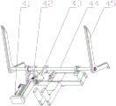
Fig. 5 is a perspective view of the turnover mechanism of the film coating turnover device of the present invention.
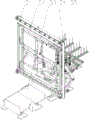
Fig. 6 is a perspective view of the film coating turnover device of the present invention.
Reference numerals:
31 rotating platform
32 contact strut
33 fixed support
34 lifting fixing plate
35 lifting power module
1 Servo rotating platform
2 walking track frame
3 power module
4-rail integrated frame
10 conveying mechanism frame
11 servo power assembly
12 unpowered passive conveying assembly
13 compressing cylinder
14 positioning cylinder
15 magnetic force wheel transmission assembly
21 clamping plate
22-guide round bar
23 carry frock frame
24 automatic locking positioning block
41 overturning power assembly
42 swing arm
43 fixed limiting assembly
44 roll-over shaft
45 turnover arm
51 jacking rotary mechanism
52 rotatable walking track
53 conveying mechanism
54 carry frock
55 turnover mechanism
Detailed Description
In order to more clearly describe the technical content of the present invention, the following further description is given with reference to specific embodiments.
The film coating turnover device of the utility model comprises a jacking rotary mechanism 51, a rotatable walking track 52, a conveying mechanism 53, a conveying tool 54 and a turnover mechanism 55, wherein the jacking rotary mechanism 51 is assembled with the rotatable walking track 52 in a matching way, the conveying mechanism 53 is arranged below the bottom of the jacking rotary mechanism 51, the conveying tool 54 is fixed on one side of the conveying mechanism 53, and the turnover mechanism 55 is fixed with the conveying mechanism 53 through a turnover arm 45 to realize the turnover of the conveying mechanism 53; the jacking rotating mechanism 51 pushes the fixed support 33 to lift through a servo electric cylinder, so as to lift the glass, and the glass is taken and placed by utilizing a clearance fit function machine between the ejector rods; the rotatable walking track 52 realizes a device which is rotatably arranged on the rotating platform 31 at any angle through the servo rotating platform 1, pushes the walking track frame 2 through the power module 3, and moves the device along the track; the conveying mechanism 53 finishes automatic in-and-out film coating of the glass; the conveying tool 54 fixes the glass.
As the preferred embodiment of the present invention, the jacking and rotating mechanism 51 comprises a fixed bracket 33, a rotating platform 31, a lifting and lowering fixed plate 34, a guide post and a contact rod 32, the rotating platform 31 is fixed with a servo electric cylinder, and the guide post is fixed on one side of the lifting and lowering fixed plate 34 by using a bolt to lock the guide post, the fixed bracket 33 is fixed on the other side of the lifting and lowering fixed plate 34 by using a bolt to lock the guide post, and the contact rod 32 is locked on the fixed bracket 33 by a rod seat.
As the utility model discloses a preferred embodiment, rotatable walking track 52 include servo rotary platform 1, walking track frame 2, power module 3 and track whole frame 4, servo rotary platform 1 install the upper surface mounting panel at walking track frame 2, power module 3 install on the inside mounting panel of track whole frame 4, power module 3's output piece is connected with walking track frame 2 through floating the joint through power output's connecting plate, walking track frame 2's both sides have the slider of 2 group symmetries, the slide rail is installed on track whole frame 4.
As the preferred embodiment of the present invention, conveying mechanism 53 include conveying mechanism frame 10, servo power assembly 11, magnetic force wheel drive assembly 15, unpowered passive conveying assembly 12, location cylinder 14 and compress tightly cylinder 13, magnetic force wheel drive assembly 15 install the bottom internal surface at conveying mechanism frame 10, servo power assembly 11 passes through bevel gear drive magnetic force wheel drive assembly 15, unpowered passive conveying assembly 12 install the upper portion internal surface at conveying mechanism frame 10, location cylinder 14 and compress tightly cylinder 13 and install respectively in the conveying frame both sides, when conveying mechanism 53 fixes a position the frock, location cylinder 14 stretches out and blocks and carries frock 54, compresses tightly cylinder 13 and pushes down the frock through the rotation.
As a preferred embodiment of the present invention, the conveying tool 54 includes a conveying tool frame 23, an automatic locking and positioning block 24, a clamping plate 21 and a guiding round bar 22, the automatic locking and positioning block 24 is installed on the front side surface of the conveying tool frame 23 to fix the glass on the tool, the guiding round bar 22 is installed at the bottom of the conveying tool frame 23, and the conveying tool frame 23 is clamped and fixed by the clamping plates 21 on both sides; the conveying tool frame 23 is matched with the magnetic wheel transmission assembly 15 of the conveying mechanism 53, and the self weight of the conveying tool 54 is utilized to realize positioning.
As a preferred embodiment of the present invention, the turning mechanism 55 includes a turning power assembly 41, a swing arm 42, a fixed limiting assembly 43, a turning shaft 44 and a turning arm 45, the swing arm 42 is connected to the turning shaft 44 through a tensioning sleeve, two sides of the turning shaft 44 are fixed by a bearing, the fixed limiting assembly 43 is installed at the center of the turning shaft 44 through the tensioning sleeve, the turning arm 45 is installed at two ends of the rotating shaft through tensioning sleeves, and the turning arm 45 and the conveying mechanism 53 are fixed by bolts; the turnover power assembly 41 is composed of a swing electric cylinder, the turnover mechanism 55 uses the turnover power assembly 41 as rotary power to push the swing arm 42, and the swing electric cylinder pushes the swing arm 42 to drive the rotating shaft to rotate, so that the conveying mechanism 53 is turned over.
The utility model discloses an among the specific embodiment, mainly include jacking rotary mechanism 51, rotatable walking track 52, conveying mechanism 53, tilting mechanism 55 and carry frock 54. The jacking and rotating mechanism 51 consists of a lifting power module 35, a guide post, a lifting fixing plate 34, a rotating platform 31 and a contact strut 32. The rotatable walking track 52 is composed of a power module 3, a walking track frame 2, a rotary support frame and a rotary mechanism. The conveying mechanism 53 consists of a magnetic wheel transmission assembly 15, an unpowered driven conveying assembly 12, a power assembly, a positioning air cylinder 14 assembly and a conveying frame. The conveying tool 54 consists of a conveying tool frame 23, an automatic locking positioning block 24, a clamping plate 21 and a guide round rod 22. The turnover mechanism 55 consists of a turnover power assembly 41, a turnover shaft 44, a turnover arm 45 and a limiting assembly.
As shown in fig. 1, the lifting power module 35 of the lifting and rotating mechanism 51 uses a servo electric cylinder as power, the fixing plate 34 of the electric cylinder is fixed on the rotating platform 31, the extension rod of the electric cylinder is locked and fixed on one side of the lifting fixing plate together with 4 guide post bolts, the fixing support 33 is made of standard aluminum profiles, the bolts are locked and fixed on the other side of the lifting fixing plate 34, the contact support rod 32 is locked on the fixing support 33 through a support rod seat, the electric cylinder pushes the fixing support 33 to lift up and down during operation, so as to lift up the glass, and other function machines can complete the loading and unloading work by utilizing the gap between the push rods.
As shown in fig. 2, the track 52 can be rotated, the track whole frame 4 is welded by carbon steel rectangular pipes, the power module 3 is installed on the installation plate inside the frame, the module output block is connected with the track frame 2 through the power output connection plate by using a floating joint, 2 sets of sliders are symmetrically arranged on two sides of the track frame 2, the slide rails are installed on the track frame 4, the walking function is realized through the slide rails and the power module 3, the servo rotary platform 1 is installed on the surface installation plate on the track frame 2, and the accurate rotation at any angle can be realized. The power module 3 pushes the walking frame 2 to move the equipment along the track, and the servo rotating platform 1 can realize accurate rotation of any angle and install the equipment on the rotating platform 31.
As shown in fig. 3, the conveying mechanism 53, the conveying mechanism frame 10 is formed by welding carbon steel pipes, the magnetic wheel transmission assembly 15 is installed on the inner surface of the bottom of the conveying mechanism frame, the power magnetic wheel transmission assembly is driven by the servo power assembly 11 through a bevel gear, the unpowered driven conveying assembly 12 is installed on the inner surface of the upper portion, the positioning air cylinders 14 and the pressing air cylinders 13 are installed on two sides of the conveying mechanism frame 10 respectively, when the conveying mechanism 53 needs to position a tool, the positioning air cylinders 14 on one side extend out to block the conveying tool 54, and the pressing air cylinders 13 on the other side rotate to press the tool, so that the tool is positioned.
As shown in fig. 4, the conveying tool 54 is formed by finish machining a conveying tool frame 23 by a stainless steel plate, the two sides of the clamping plate 21 are clamped and fixed, the bottom of the conveying tool 54 is provided with a guide circle 22, the magnetic wheel transmission assembly 15 of the matched conveying mechanism 53 realizes positioning by the dead weight of the conveying tool 54, the front side surface of the conveying tool 54 is provided with an automatic locking positioning block 24, and the automatic locking positioning block 24 can fix glass on the tool.
As shown in fig. 5, the turning mechanism 55 uses a turning power assembly 41 composed of swing electric cylinders as a rotating power to push the swing arm 42, the swing arm is connected with the turning shaft 44 through a tensioning sleeve 42, two sides of the turning shaft 44 are fixed by bearings, a limiting assembly 43 fixed by the tensioning sleeve is installed at the center of the turning shaft 44 to prevent accidents, the electric cylinders push the swing arm 42 to drive the rotating shaft to rotate, two ends of the rotating shaft are respectively provided with a turning arm 45 by the tensioning sleeve, and the turning arm 42 and the conveying mechanism 53 are fixed by bolts to realize the turning function of the conveying mechanism 55.
As shown in fig. 6, the coating inverting device is integrally assembled as shown in the figure.
By adopting the film coating turnover device of the utility model, two inlets of the film coating machine can be butted through the moving function of the walking mechanism; the rotating function of the traveling mechanism ensures that the orientation of the glass coating surface is aligned to the correct coating direction when the glass coating surface is coated inside the coating machine; the glass taking and placing machine is realized by matching the jacking rotating mechanism with other functional machines (robots or other special machine for taking and placing the glass), and the automatic glass feeding and discharging of the coating machine are completed by the conveying mechanism; the glass is fixed in position by utilizing the conveying tool, so that convenience is realized. The components are matched with each other to work, so that the function of automatically finishing film coating of the ultrathin luminous glass is realized.
In this specification, the invention has been described with reference to specific embodiments thereof. It will, however, be evident that various modifications and changes may be made thereto without departing from the broader spirit and scope of the invention. The specification and drawings are, accordingly, to be regarded in an illustrative rather than a restrictive sense.
Claims (6)
1. The coating film overturning device is characterized by comprising a jacking rotating mechanism (51), a rotatable walking track (52), a conveying mechanism (53), a conveying tool (54) and an overturning mechanism (55), wherein the jacking rotating mechanism (51) is assembled with the rotatable walking track (52) in a matching manner, the conveying mechanism (53) is arranged below the bottom of the jacking rotating mechanism (51), the conveying tool (54) is fixed on one side of the conveying mechanism (53), and the overturning mechanism (55) is fixed with the conveying mechanism (53) through an overturning arm (45) so as to realize overturning of the conveying mechanism (53); the jacking rotating mechanism (51) pushes the fixed support (33) to lift through the servo electric cylinder, so as to lift the glass, and the glass is taken and placed by utilizing a clearance fit function machine between the ejector rods; the rotatable walking track (52) is a device which is rotatably arranged on the rotating platform (31) at any angle through the servo rotating platform (1), and the walking track rack (2) is pushed by the power module (3) to move along the track; the conveying mechanism (53) finishes automatic in-and-out film coating of the glass; the conveying tool (54) fixes the glass.
2. The coating film turnover device according to claim 1, wherein the jacking and rotating mechanism (51) comprises a fixed support (33), a rotating platform (31), a lifting and fixing plate (34), a guide post and a contact support rod (32), a servo electric cylinder is fixed on the rotating platform (31), the servo electric cylinder is locked and fixed on one side of the lifting and fixing plate (34) through the guide post on the servo electric cylinder by using a bolt, the fixed support (33) is locked and fixed on the other side of the lifting and fixing plate (34) through the bolt, and the contact support rod (32) is locked and fixed on the fixed support (33) through a support rod seat.
3. The coating film turnover device according to claim 1, wherein the rotatable traveling rail (52) comprises a servo rotating platform (1), a traveling rail frame (2), a power module (3) and a rail integral frame (4), the servo rotating platform (1) is mounted on an upper surface mounting plate of the traveling rail frame (2), the power module (3) is mounted on a mounting plate inside the rail integral frame (4), an output block of the power module (3) is connected with the traveling rail frame (2) through a power output connecting plate through a floating joint, two sides of the traveling rail frame (2) are provided with 2 sets of symmetrical sliding blocks, and a sliding rail is mounted on the rail integral frame (4).
4. The coating film turnover device according to claim 1, wherein the conveying mechanism (53) comprises a conveying mechanism frame (10), a servo power assembly (11), a magnetic wheel transmission assembly (15), a non-powered passive conveying assembly (12), a positioning cylinder (14) and a pressing cylinder (13), the magnetic wheel transmission assembly (15) is arranged on the inner surface of the bottom of the conveying mechanism frame (10), the servo power assembly (11) drives the magnetic wheel transmission assembly (15) through a bevel gear, the unpowered passive conveying component (12) is arranged on the inner surface of the upper part of the conveying mechanism frame (10), the positioning cylinder (14) and the pressing cylinder (13) are respectively arranged at two sides of the conveying frame, when the conveying mechanism (53) positions the tool, the positioning cylinder (14) extends out of the blocking conveying tool (54), and the pressing cylinder (13) presses the tool through rotation.
5. The coating film turnover device according to claim 1, wherein the conveying tool (54) comprises a conveying tool frame (23), an automatic locking positioning block (24), a clamping plate (21) and a guiding round bar (22), the automatic locking positioning block (24) is arranged on the front side surface of the conveying tool frame (23) to fix the glass on the tool, the guiding round bar (22) is arranged at the bottom of the conveying tool frame (23), and the conveying tool frame (23) is clamped and fixed by the clamping plates (21) on two sides; the magnetic wheel transmission assembly (15) of the conveying mechanism (53) is matched with the conveying tool frame (23), and the self weight of the conveying tool (54) is utilized to realize positioning.
6. The coating film turnover device according to claim 1, wherein the turnover mechanism (55) comprises a turnover power assembly (41), a swing arm (42), a fixed limiting assembly (43), a turnover shaft (44) and a turnover arm (45), the swing arm (42) is connected with the turnover shaft (44) through a tensioning sleeve, two sides of the turnover shaft (44) are fixed through bearings, the fixed limiting assembly (43) is installed at the central part of the turnover shaft (44) through the tensioning sleeve, the turnover arm (45) is respectively installed at two ends of the rotating shaft through tensioning sleeves, and the turnover arm (45) is fixed with the conveying mechanism (53) through bolts; the turnover power assembly (41) is composed of a swing electric cylinder, the turnover mechanism (55) takes the turnover power assembly (41) as rotary power to push the swing arm (42), and the swing electric cylinder pushes the swing arm (42) to drive the rotary shaft to rotate so as to realize turnover of the conveying mechanism (53).
Priority Applications (1)
| Application Number | Priority Date | Filing Date | Title |
|---|---|---|---|
| CN202120281053.0U CN214455036U (en) | 2021-02-01 | 2021-02-01 | Coating film turning device |
Applications Claiming Priority (1)
| Application Number | Priority Date | Filing Date | Title |
|---|---|---|---|
| CN202120281053.0U CN214455036U (en) | 2021-02-01 | 2021-02-01 | Coating film turning device |
Publications (1)
| Publication Number | Publication Date |
|---|---|
| CN214455036U true CN214455036U (en) | 2021-10-22 |
Family
ID=78117264
Family Applications (1)
| Application Number | Title | Priority Date | Filing Date |
|---|---|---|---|
| CN202120281053.0U Active CN214455036U (en) | 2021-02-01 | 2021-02-01 | Coating film turning device |
Country Status (1)
| Country | Link |
|---|---|
| CN (1) | CN214455036U (en) |
-
2021
- 2021-02-01 CN CN202120281053.0U patent/CN214455036U/en active Active
Similar Documents
| Publication | Publication Date | Title |
|---|---|---|
| CN201065143Y (en) | Multi-axle multi-station suspension carrying robot | |
| EP0734941B1 (en) | Flexible body framing system | |
| CN211728240U (en) | Conveying system | |
| CN110681976B (en) | Aluminum alloy wheel friction stir welding duplex position automatic clamping system | |
| CN206445408U (en) | Multi-vehicle-type white body welds total built-up jig | |
| CN112374106A (en) | Automatic transfer, turnover and conveying equipment | |
| CN210475941U (en) | Axle housing reinforcing ring rear cover welding station | |
| CN113681303A (en) | Welding production line for cabin short rib | |
| CN214455036U (en) | Coating film turning device | |
| CN112828507A (en) | Gantry type automatic welding equipment | |
| CN112404806A (en) | Automatic assembling and welding device and method for bent ribs | |
| US6364817B1 (en) | Automotive framing apparatus | |
| CN112777322A (en) | Coating film turning device | |
| CN217596328U (en) | Welding production line system for arm body of climbing vehicle crank arm | |
| CN107598523B (en) | Brake disc preassembling device and method | |
| CN115971781A (en) | Steel pipe longitudinal seam welding machine | |
| CN210456437U (en) | Automatic turnover device for forklift portal channel steel machining | |
| CN114789327B (en) | Robot assembly system for realizing robot body assembly by fixing transportation mechanical arm | |
| CN219652143U (en) | Rotor transporting and clamping device | |
| CN218908921U (en) | Be used for automatic semi-axis integrated form transfer car (buggy) of wearing of rear axle case | |
| CN212443962U (en) | Positioning device for assembling integrated steel tongue plate and tongue plate assembly line of integrated steel tongue plate | |
| CN215880720U (en) | Welding production line for cabin short rib | |
| CN218109814U (en) | Inner container accessory welding tool | |
| CN116060738B (en) | Vertical assembly device for aluminum alloy powder tank body | |
| CN216807379U (en) | Automatic loading device |
Legal Events
| Date | Code | Title | Description |
|---|---|---|---|
| GR01 | Patent grant | ||
| GR01 | Patent grant |