EP1351343B1 - Electrical apparatus with a fast electrical connection to the mains, specially for waterproofed lamp holders - Google Patents
Electrical apparatus with a fast electrical connection to the mains, specially for waterproofed lamp holders Download PDFInfo
- Publication number
- EP1351343B1 EP1351343B1 EP03352006A EP03352006A EP1351343B1 EP 1351343 B1 EP1351343 B1 EP 1351343B1 EP 03352006 A EP03352006 A EP 03352006A EP 03352006 A EP03352006 A EP 03352006A EP 1351343 B1 EP1351343 B1 EP 1351343B1
- Authority
- EP
- European Patent Office
- Prior art keywords
- electrical
- support
- connection support
- connection
- aperture
- Prior art date
- Legal status (The legal status is an assumption and is not a legal conclusion. Google has not performed a legal analysis and makes no representation as to the accuracy of the status listed.)
- Expired - Lifetime
Links
- 238000007789 sealing Methods 0.000 claims abstract description 41
- 239000012530 fluid Substances 0.000 claims abstract description 8
- 230000009975 flexible effect Effects 0.000 claims description 11
- 238000006073 displacement reaction Methods 0.000 claims description 9
- 230000000295 complement effect Effects 0.000 claims description 4
- 230000000694 effects Effects 0.000 claims description 3
- 230000000717 retained effect Effects 0.000 claims 1
- 238000000605 extraction Methods 0.000 description 3
- 229920001971 elastomer Polymers 0.000 description 2
- 238000003780 insertion Methods 0.000 description 2
- 230000037431 insertion Effects 0.000 description 2
- 239000000463 material Substances 0.000 description 2
- 230000006866 deterioration Effects 0.000 description 1
- 239000000806 elastomer Substances 0.000 description 1
- 239000007788 liquid Substances 0.000 description 1
- 238000012423 maintenance Methods 0.000 description 1
- 230000007935 neutral effect Effects 0.000 description 1
- 230000035939 shock Effects 0.000 description 1
Images


Classifications
-
- H—ELECTRICITY
- H01—ELECTRIC ELEMENTS
- H01R—ELECTRICALLY-CONDUCTIVE CONNECTIONS; STRUCTURAL ASSOCIATIONS OF A PLURALITY OF MUTUALLY-INSULATED ELECTRICAL CONNECTING ELEMENTS; COUPLING DEVICES; CURRENT COLLECTORS
- H01R13/00—Details of coupling devices of the kinds covered by groups H01R12/70 or H01R24/00 - H01R33/00
- H01R13/46—Bases; Cases
- H01R13/52—Dustproof, splashproof, drip-proof, waterproof, or flameproof cases
- H01R13/5202—Sealing means between parts of housing or between housing part and a wall, e.g. sealing rings
-
- H—ELECTRICITY
- H01—ELECTRIC ELEMENTS
- H01R—ELECTRICALLY-CONDUCTIVE CONNECTIONS; STRUCTURAL ASSOCIATIONS OF A PLURALITY OF MUTUALLY-INSULATED ELECTRICAL CONNECTING ELEMENTS; COUPLING DEVICES; CURRENT COLLECTORS
- H01R13/00—Details of coupling devices of the kinds covered by groups H01R12/70 or H01R24/00 - H01R33/00
- H01R13/73—Means for mounting coupling parts to apparatus or structures, e.g. to a wall
- H01R13/74—Means for mounting coupling parts in openings of a panel
- H01R13/741—Means for mounting coupling parts in openings of a panel using snap fastening means
Definitions
- the present invention relates to electrical apparatus requiring for their operating a connection by external electrical wires to a power supply external, comprising a sealed housing inside which is a device electrical device intended to be powered by said external electrical wires, said housing having an opening through which said external power supply via said electrical wires is destined to pass.
- the opening has the function of allowing the electrical wires to pass through the wall of the housing sealed, via a watertight crossing, the electrical connection of the wires being effected on appropriate terminal blocks inside the housing.
- the operator closes the housing of the device which is then functional.
- the luminaries such a structure and impose an opening or reopening of the housing to make the electrical connection to the network, after being fixed on their support, usually a wall or a ceiling.
- the operation of electrical connection requires time, which is repeated many times corresponding to the equipment of a building is far from negligible.
- the operation of opening or reopening the housing may cause risks of deterioration of the connection means of the housing, generally consisting of a fixed shell the support and a translucent basin for the luminaires, the latter being fixed at hull, or risks of faulty sealing of the housing when reassembling it.
- An electrical appliance of this type is described in EP0905829.
- the apparatus according to the invention allows an electrical connection thereof to the power supply without opening or dismounting the waterproof case thanks to its mobile connection support, advantageously extractable, which allows a connection, to the outside of the waterproof housing, external electrical wires to the device via the electrical connection support.
- the electrical connection is made, it is sufficient to an operator to place the connection support in its operating position and the lock.
- the sealing means cooperate with the connection support when it is in the operating position, and advantageously with the locking means, in order to seal the fluid opening in this position, conferring on the the apparatus according to the invention the qualifier fluid-tight and more particularly to liquids.
- the apparatus according to the invention comprises means for guiding the displacement of said electrical connection support through said opening, from said first to said second position.
- the means for guiding the displacement of the support advantageously allow to facilitate the extraction operation of the support and the maintenance of the support in the second position in which the operator realizes, on the outside of the sealed housing, the connection between the external electrical supply wires and the internal electrical network of the device.
- said guide means comprise means for guiding said support in translation in said opening, giving the connection medium mobility similar to that of a drawer.
- said sealing means comprise a sealing element adapted to be associated with a part of said support of electrical connection which protrudes outside said sealed housing in said first position of the support, said sealing member forming, when associated with said portion electrical connection bracket, sealing on the power cable external and on said waterproof housing.
- this characteristic allows the operator to achieve a quick seal and easy in the operating position of the connection support, by means of a single element ensuring when it is put in place all the necessary seals.
- said locking means further comprise clip attachment means of said connection support in said opening and in the first position.
- said fastening means by clip said connection support in said opening and in the first position comprise at least two elastic flexible tabs placed in opposition, capable of engage in said opening so as to define said first position of the support and ensure the fixing of the latter in said first position.
- said fastening means by clip said electrical connection support in said opening and in the first position comprise at least one part protruding outside said sealed housing, with a view to allow their input by an operator to release said fastening means by clip and allow said operator a displacement of said electrical connection support of the first to second position.
- said sealing element comprises security means cooperating with said clip fixing means for the purpose of secure the locking of said support in the first position.
- said electrical connection support comprises a stop capable of limiting its movement to said second position and defining thus said second position of the support.
- said opening adopts a section circular and in that said electrical connection support adopts a cylindrical shape of partially circular cross section complementary to the cross section of said opening.
- This characteristic allows the apparatus according to the invention to provide a support electrical connection which can be installed in a relatively circular opening small, for example the size of that equipping the known waterproof devices requiring an opening of their housing to make the connection to the power supply, and in which the opening is intended for the passage of electrical supply wires via a grommet or the like.
- connection support comprises a plurality of terminal blocks allowing a wire-to-wire connection between said electrical wires external power supply and said power distribution network internal to said device, respectively.
- the present invention is particularly applicable to waterproof luminaires.
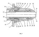
- FIG. 1 represents the connection support 3 and the housing 1 separately, the connection support 3 being in position to be inserted into the opening 2 of the housing, this following a movement of the support in the direction 7, this insertion operation of the support in the housing via the opening 2 being normally performed at the factory during assembly of the electrical appliance.
- Figure 2 illustrates the following step in the factory assembly of the device, the connection support being put in place in the opening 2 of the housing and immobilized in the first position, as will be explained later.
- Figure 2 we have represented the internal electrical distribution network 4 connected to the connection support Electric 3.
- Figure 3 illustrates another step of factory assembly of the apparatus consisting of to set up a sealing element 6 on the connection support 3 connected to the opening 2, as will also be explained later.
- the apparatus as partially shown in Figure 3 is ready to be placed on a support (not shown), wall or ceiling for example in the case of a luminaire sealed, then to be connected to the power supply wires 5, operations shown in Figures 4 to 6.
- Figure 4 shows the electrical apparatus in place on its support (no shown), from which the sealing element 6 has been removed in order to allow the extraction of the connection support out of the housing 1, as will be explained later, and the electrical connection with the power wires 5 which have been shown in Figure 4 adjacent to the connection support.
- FIG. 5 illustrates the connection support in its second position, outside the casing 1 waterproof, in which the electrical connection with the supply leads electrical 5 is actually made, as shown in the figure.
- FIG. 6 shows the connection support 3 in its operating position, the connection support having been pushed inside the housing after having made the electrical connection to the power supply and the sealing means having been put in place, as shown.
- the opening 2 adopts, for example, a section circular, corresponding to the opening section generally used for the passage electrical supply wires in an electrical appliance
- the support 3 of electrical connection comprises a main body 11 which adopts the shape of a wall cylindrical 13 of semicircular cross-section complementary to the section transverse opening 2, so that the circular border 8 defining the opening 2 serves advantageously means for guiding the support 3 in translation during its moving from the first to the second position.
- the main body of the support 3 is hollow so that the terminal blocks 9 of the network connection internal power distribution with the external power cables are attached to the semicircular wall of the support and can register in the circular section of passage of the opening 2.
- connection support 3 comprises a plurality of terminal blocks 9 allowing a wire-to-wire connection between the external electrical wires 5 of the external power supply and the power distribution network 4 internal to the device, respectively, as shown in FIG. 5 or 6.
- the length of the connection support 3 is therefore defined in a manner appropriate according to the number of terminal blocks 9 to be placed on the support 3 according to the network internal electrical distribution and the type of power supply.
- three terminal blocks 9 are required at least, representing the phase, the neutral, and the earth, for a current household power supply, as shown in the figures.
- connection support 3 advantageously comprises a part 10 suitable for making protruding outside the housing 1 waterproof in the first position of the support 3, as shown in FIG. 2 for example, this part being tubular with a circular section and extending along the longitudinal axis 12 of the cylindrical section of the main body 11 of 3.
- the junction between the tubular portion 10 and the semicircular wall 13 is performed for example by means of a transverse connecting disc 14, as shown in Figure 1 for example.
- the sealing means comprise a sealing element 6 adapted to be associated with the tubular portion of the electrical connection support 3 which protrudes out of the casing 1 sealed in the first position of the support, the sealing element 6 forming, when associated with the part 10 of the electrical connection support 3, a seal on the external power supply cable 14 and the waterproof housing 1, as shown in Figures 6 and 7.
- the sealing element 6 adopts the shape of a cabochon comprising at a end 15 a hole 16 with a diameter slightly smaller than the outside diameter of the cable power supply 14 so as to ensure fluid tightness between the hole 16 and the cable 14, and at the other end an outer surface 17 in the form of a ring intended to bear on the housing 1 to ensure fluid tightness between the outer surface 17 in the form of a ring and the housing 1 waterproof.
- the sealing element 6 is made of a flexible waterproof material, for example rubber, elastomer etc. ...
- the sealing element 6 may be made of a material rigid (not shown) or semi-rigid which can be fixed by clipping on the part tube of the connection support, and having flexible parts in the zones of contact with the power cable and the waterproof housing, intended to ensure watertightness with these.
- the seal element 6 further comprises a flange 18 circular interior intended to be housed in a complementary groove 19 of the part tubular connection support, to ensure a connection between the support 3 and the sealing element, as shown in Figure 7.
- the connection of the element 6 with the tubular portion 10 of the connection support 3 is preferably tight as it can thus advantageously double a first sealing provided at the end 15 of the sealing member.
- the locking means further comprise clip fastening means 20 of the support 3 of electrical connection in the opening 2 and in the first position of the support or operating position, as shown in FIGS. 2 and 7 especially.
- the fixing means 20 for clip 20 of the connection support 3 in the opening comprise two elastic flexible tabs 21 placed in opposition, adapted to to engage in the opening 2 so as to define the first position of the support 3 and ensure the fixation of the latter in this first position, as shown on Figures 2 or 7.
- the tabs 21 extend in the longitudinal extension of the wall semicircular 13 and diametrically opposite, on the side of the tubular portion 10, as shown in FIG.
- each of the legs 21 are spaced a distance of the order of, or slightly less than, the thickness of the wall of the sealed housing 1 so to immobilize this wall between the stops 22 and 24 as shown in FIG. two stops 22 of the two tabs 21 closest to the end thereof, respectively, are provided with a gentle slope 23 intended to allow a deflection each leg 21 under the action of a thrust of the support in the opening 2 made by the operator, until the wall of the sealed housing crosses the stops 22. Then, by elasticity, the legs return to their initial position and the wall comes to a standstill between the stops 22 and 24 of each leg 21.
- the connection support 3 is totally bound in the opening 2 of the housing, no degree of freedom between the two parts.
- the fastening means 20 for clip 20 of the support 3 for electrical connection in the opening 2 and in the first position have at least one projecting portion 25 outside the sealed housing 1, to allow their input by an operator for release the fixing means by clip and allow the operator a displacement of the support 3 electrical connection from the first to the second position.
- the tabs 21 extend advantageously beyond the opening 2 to the outside of the housing, so that an operator can, between two of fingers, for example, grasping the two legs and bringing them closer to one another their flexibility in order to release the wall of the housing 1 from the stops 22 and 24 of each leg, and to be able to remove the connection support to the outside of the housing in its second position, as shown in Figure 5, and make the electrical connection in this position.
- the end of the support of connection 3 opposite to that carrying the tubular portion 10 comprises a stop 26 adapted to limit the movement of the support to the second position and thus define this second position of the support, for example by taking support on the wall of the housing 1 waterproof when the support is extracted from the housing in second position.
- this stop adopts the shape of a half-disc of diameter greater than that of the opening 2 of the housing.
- the semicircular wall 13 makes it possible to form a connection in a single degree of freedom in translation of the support
- the stop 26 makes it possible to limit this displacement by translation in the direction of the extraction of the support out of the housing
- the flexible tabs 21 allow to limit, via stops 22 and 24, the displacement in translation towards the first position, and further prevent the support 3 from falling into the housing.
- any other additional stop means (not shown) preventing the support is projected in the sealed housing 1 following a bad maneuver of the operator, can be used, for example a removable stop (not shown) placed behind the stop 26 which would be put in place after the insertion of the support 3 in the opening 2.
- the sealing element 6 further comprises safety means 27 cooperating with the clip fixing means 20 for securing the locking of the support 3 in the first position, as shown in Figure 7.
- These security means adopt in the example the form of a tubular ring 28 longitudinal capable of surrounding the tubular portion 10 of the support 3, and come to be housed when the sealing element 6 is inserted around the tubular portion 10 of the support, between the latter and the flexible tabs 21 of the support to prevent the legs 21 from being released from the wall of the casing inadvertently once the support 3 is in its first position, and when the sealing element 6 is in place on the tubular part of the support, as represented in FIG. 7.
- the tubular portion 10 of the support is advantageously provided with a chamfer 29 ending with a rounded 30 to facilitate the crossing of the end of this tubular part by the ring 28 of the sealing element 6, and also by the flange circular 18.
- the apparatus according to the invention can be disconnected from the network external power supply by the reverse operations of those described above, ie also without opening the device.
Abstract
Description
La présente invention se rapporte aux appareils électriques nécessitant pour leur fonctionnement un raccordement par fils électriques externes à une alimentation électrique externe, comprenant un boítier étanche à l'intérieur duquel se trouve un dispositif électrique destiné à être alimenté par lesdits fils électriques externes, ledit boítier comportant une ouverture à travers laquelle ladite alimentation électrique externe via lesdits fils électriques est destinée à passer.The present invention relates to electrical apparatus requiring for their operating a connection by external electrical wires to a power supply external, comprising a sealed housing inside which is a device electrical device intended to be powered by said external electrical wires, said housing having an opening through which said external power supply via said electrical wires is destined to pass.
Avec ce type d'appareil électrique, il est nécessaire d'ouvrir le boítier ou l'enveloppe de l'appareil afin de raccorder ce dernier, et plus particulièrement le dispositif électrique se trouvant à l'intérieur du boítier, à l'alimentation électrique. En effet, l'ouverture a pour fonction de permettre aux fils électriques de traverser la paroi du boítier étanche, via une traversée étanche, la connexion électrique des fils s'effectuant sur des borniers appropriés à l'intérieur du boítier. Une fois le raccordement électrique effectué, l'opérateur referme le boítier de l'appareil qui est alors fonctionnel. Les luminaires étanches adoptent par exemple une telle structure et imposent une ouverture ou réouverture du boítier afin de réaliser le raccordement électrique au réseau, après avoir été fixés sur leur support, généralement un mur ou un plafond. De ce fait, l'opération de raccordement électrique demande du temps, lequel répété un nombre de fois important correspondant à l'équipement d'un immeuble est loin d'être négligeable. De plus, l'opération d'ouverture ou de réouverture du boítier peut engendrer des risques de détérioration des moyens de liaison du boítier, généralement constitué d'une coque fixée au support et d'une vasque translucide pour les luminaires, cette dernière étant fixée à la coque, ou des risques d'étanchéité défaillante du boítier au remontage de celui-ci. Un appareil électrique de ce type est décrit dans le document EP0905829.With this type of electrical device, it is necessary to open the housing or the envelope of the device in order to connect it, and more particularly the device electrical located inside the housing, the power supply. Indeed, the opening has the function of allowing the electrical wires to pass through the wall of the housing sealed, via a watertight crossing, the electrical connection of the wires being effected on appropriate terminal blocks inside the housing. Once the electrical connection is made, the operator closes the housing of the device which is then functional. The luminaries such a structure and impose an opening or reopening of the housing to make the electrical connection to the network, after being fixed on their support, usually a wall or a ceiling. As a result, the operation of electrical connection requires time, which is repeated many times corresponding to the equipment of a building is far from negligible. Moreover, the operation of opening or reopening the housing may cause risks of deterioration of the connection means of the housing, generally consisting of a fixed shell the support and a translucent basin for the luminaires, the latter being fixed at hull, or risks of faulty sealing of the housing when reassembling it. An electrical appliance of this type is described in EP0905829.
La présente invention se propose de pallier ces inconvénients. Plus précisément, elle consiste en un appareil électrique nécessitant un raccordement par fils électriques externes à une alimentation électrique externe, comprenant un boítier étanche à l'intérieur duquel se trouve un dispositif électrique destiné à être alimenté par lesdits fils électriques externes, ledit boítier comportant une ouverture à travers laquelle ladite alimentation électrique externe via lesdits fils électriques est destinée à passer, ledit appareil électrique étant caractérisé en ce qu'il comprend
- un support de connexion électrique, lié à ladite ouverture, permettant un raccordement
électrique entre un réseau de distribution électrique interne au dit appareil et lesdits fils
électriques externes, ledit support de connexion étant mobile entre deux positions,
une première position, dite de fonctionnement, dans laquelle ledit support de connexion se trouve à l'intérieur dudit boítier étanche, et
une deuxième position, dite de raccordement électrique, dans laquelle ledit support se trouve au moins en partie à l'extérieur dudit boítier étanche, de manière à permettre notamment une opération de raccordement desdits fils électriques externes d'alimentation au dit appareil, - des moyens de verrouillage dudit support de connexion dans ladite première position,
- des moyens d'étanchéité permettant d'empêcher le passage d'un fluide de l'extérieur vers l'intérieur dudit boítier via ladite ouverture dans la position de fonctionnement dudit support de connexion.
- an electrical connection support, connected to said opening, allowing an electrical connection between an electrical distribution network internal to said apparatus and said external electrical wires, said connection support being movable between two positions,
a first operating position, in which said connection support is inside said sealed housing, and
a second position, called electrical connection, wherein said support is located at least partly outside said sealed housing, so as to allow such a connection operation of said external power supply son to said apparatus, - means for locking said connection support in said first position,
- sealing means for preventing the passage of a fluid from the outside to the inside of said housing via said opening in the operating position of said connection support.
L'appareil selon l'invention permet un raccordement électrique de celui-ci à l'alimentation électrique sans ouverture ou démontage du boítier étanche grâce à son support de connexion mobile, avantageusement extractible, qui permet une connexion, à l'extérieur du boítier étanche, des fils électriques externes d'alimentation à l'appareil via le support de connexion électrique. Une fois le raccordement électrique effectué, il suffit à un opérateur de placer le support de connexion dans sa positon de fonctionnement et de le verrouiller. Les moyens d'étanchéité coopèrent avec le support de connexion lorsqu'il est dans la position de fonctionnement, et avantageusement avec les moyens de verrouillage, afin d'assurer l'étanchéité de l'ouverture aux fluides dans cette position, conférant à l'appareil selon l'invention le qualificatif d'étanche aux fluides et plus particulièrement aux liquides.The apparatus according to the invention allows an electrical connection thereof to the power supply without opening or dismounting the waterproof case thanks to its mobile connection support, advantageously extractable, which allows a connection, to the outside of the waterproof housing, external electrical wires to the device via the electrical connection support. Once the electrical connection is made, it is sufficient to an operator to place the connection support in its operating position and the lock. The sealing means cooperate with the connection support when it is in the operating position, and advantageously with the locking means, in order to seal the fluid opening in this position, conferring on the the apparatus according to the invention the qualifier fluid-tight and more particularly to liquids.
Selon une caractéristique avantageuse, l'appareil selon l'invention comprend des moyens de guidage du déplacement dudit support de connexion électrique à travers ladite ouverture, de ladite première à ladite deuxième position.According to an advantageous characteristic, the apparatus according to the invention comprises means for guiding the displacement of said electrical connection support through said opening, from said first to said second position.
Les moyens de guidage du déplacement du support permettent avantageusement de faciliter l'opération d'extraction du support et le maintien du support dans la deuxième position dans laquelle l'opérateur réalise, à l'extérieur du boítier étanche, la connexion électrique entre les fils électriques externes d'alimentation et le réseau électrique interne de l'appareil.The means for guiding the displacement of the support advantageously allow to facilitate the extraction operation of the support and the maintenance of the support in the second position in which the operator realizes, on the outside of the sealed housing, the connection between the external electrical supply wires and the internal electrical network of the device.
Selon une autre caractéristique avantageuse, lesdits moyens de guidage comprennent des moyens de guidage en translation dudit support dans ladite ouverture, conférant au support de connexion une mobilité semblable à celle d'un tiroir.According to another advantageous characteristic, said guide means comprise means for guiding said support in translation in said opening, giving the connection medium mobility similar to that of a drawer.
Selon une autre caractéristique avantageuse, lesdits moyens d'étanchéité comprennent un élément d'étanchéité apte à être associé à une partie dudit support de connexion électrique qui fait saillie à l'extérieur dudit boítier étanche dans ladite première position du support, ledit élément d'étanchéité formant, lorsqu'il est associé à ladite partie du support de connexion électrique, une étanchéité sur le câble d'alimentation électrique externe et sur ledit boítier étanche.According to another advantageous characteristic, said sealing means comprise a sealing element adapted to be associated with a part of said support of electrical connection which protrudes outside said sealed housing in said first position of the support, said sealing member forming, when associated with said portion electrical connection bracket, sealing on the power cable external and on said waterproof housing.
Ainsi, cette caractéristique permet à l'opérateur de réaliser une étanchéité rapide et aisée dans la position de fonctionnement du support de connexion, au moyen d'un élément unique assurant lors de sa mise en place toutes les étanchéités nécessaires.Thus, this characteristic allows the operator to achieve a quick seal and easy in the operating position of the connection support, by means of a single element ensuring when it is put in place all the necessary seals.
Selon une autre caractéristique avantageuse, lesdits moyens de verrouillage comprennent en outre des moyens de fixation par clip dudit support de connexion électrique dans ladite ouverture et dans la première position.According to another advantageous characteristic, said locking means further comprise clip attachment means of said connection support in said opening and in the first position.
Selon une autre caractéristique avantageuse, lesdits moyens de fixation par clip dudit support de connexion dans ladite ouverture et dans la première position comprennent au moins deux pattes flexibles élastiques placées en opposition, aptes à se mettre en prise dans ladite ouverture de manière à définir ladite première position du support et assurer la fixation de ce dernier dans cette dite première position.According to another advantageous characteristic, said fastening means by clip said connection support in said opening and in the first position comprise at least two elastic flexible tabs placed in opposition, capable of engage in said opening so as to define said first position of the support and ensure the fixing of the latter in said first position.
Selon une autre caractéristique avantageuse, lesdits moyens de fixation par clip dudit support de connexion électrique dans ladite ouverture et dans la première position comportent au moins une partie faisant saillie à l'extérieur dudit boítier étanche, en vue de permettre leur saisie par un opérateur pour libérer lesdits moyens de fixation par clip et permettre au dit opérateur un déplacement dudit support de connexion électrique de la première à la deuxième position.According to another advantageous characteristic, said fastening means by clip said electrical connection support in said opening and in the first position comprise at least one part protruding outside said sealed housing, with a view to allow their input by an operator to release said fastening means by clip and allow said operator a displacement of said electrical connection support of the first to second position.
Selon une autre caractéristique avantageuse, ledit élément d'étanchéité comprend des moyens de sécurité coopérant avec lesdits moyens de fixation par clip en vue de sécuriser le verrouillage dudit support dans la première position.According to another advantageous characteristic, said sealing element comprises security means cooperating with said clip fixing means for the purpose of secure the locking of said support in the first position.
Selon une autre caractéristique avantageuse, ledit support de connexion électrique comprend une butée apte à limiter son déplacement à ladite deuxième position et définir ainsi ladite deuxième position du support.According to another advantageous characteristic, said electrical connection support comprises a stop capable of limiting its movement to said second position and defining thus said second position of the support.
Selon une autre caractéristique avantageuse, ladite ouverture adopte une section circulaire et en ce que ledit support de connexion électrique adopte une forme cylindrique de section transversale partiellement circulaire complémentaire de la section transversale de ladite ouverture.According to another advantageous characteristic, said opening adopts a section circular and in that said electrical connection support adopts a cylindrical shape of partially circular cross section complementary to the cross section of said opening.
Cette caractéristique permet à l'appareil selon l'invention de pourvoir à un support de connexion électrique qui peut être installé dans une ouverture circulaire relativement petite, par exemple de la taille de celle équipant les appareils étanches connus nécessitant une ouverture de leur boítier afin de réaliser la connexion à l'alimentation électrique, et dans lesquels l'ouverture est destinée au passage des fils électriques d'alimentation via un passe-fil ou analogue.This characteristic allows the apparatus according to the invention to provide a support electrical connection which can be installed in a relatively circular opening small, for example the size of that equipping the known waterproof devices requiring an opening of their housing to make the connection to the power supply, and in which the opening is intended for the passage of electrical supply wires via a grommet or the like.
Selon une autre caractéristique avantageuse, ledit support de connexion comprend une pluralité de borniers permettant un raccord fil à fil entre lesdits fils électriques externes de l'alimentation électrique externe et ledit réseau de distribution électrique interne au dit appareil, respectivement.According to another advantageous characteristic, said connection support comprises a plurality of terminal blocks allowing a wire-to-wire connection between said electrical wires external power supply and said power distribution network internal to said device, respectively.
La présente invention est applicable notamment aux luminaires étanches.The present invention is particularly applicable to waterproof luminaires.
La présente invention sera mieux comprise et d'autres caractéristiques et avantages
apparaítront à la lecture de la description qui suit d'un exemple de mode de réalisation
d'un appareil électrique selon l'invention, accompagnée des dessins annexés, exemple
donné à titre illustratif non limitatif.
L'appareil électrique représenté sur les figures 1 à 7 nécessite un raccordement par fils électriques externes à une alimentation électrique externe, et comprend un boítier ou enveloppe étanche 1, représenté partiellement sur les figures afin de simplifier celles-ci, à l'intérieur duquel se trouve un dispositif électrique (non représenté), par exemple une ou plusieurs lampes dans le cas d'un luminaire étanche, destiné à être alimenté par les fils électriques externes, le boítier 1 comportant une ouverture 2 à travers laquelle l'alimentation électrique externe via les fils électriques est destinée à passer. Sur les figures le boítier a été représenté seulement dans le voisinage de l'ouverture. L'appareil électrique représenté sur les figures 1 à 7 comprend en outre :
- un
support 3 de connexion électrique, apte à être lié à l'ouverture 2, comme représenté sur les figures 2 à 7, permettant un raccordement électrique entre un réseau de distribution électrique 4 interne à l'appareil et les fils électriques externes, le support deconnexion 3 étant mobile entre deux positions,
une première position, dite de fonctionnement, comme représenté sur la figure 2, 3, 4, 6 ou 7, dans laquelle le support deconnexion 3 se trouve à l'intérieur du boítier étanche 1, et
une deuxième position, dite de raccordement électrique, comme représenté sur la figure 5, dans laquelle lesupport 3 se trouve au moins en partie à l'extérieur du boítier étanche 1, de manière à permettre notamment une opération de raccordement des fils électriques 5 externes d'alimentation à l'appareil, - des moyens de
verrouillage 20 dusupport 3 de connexion dans la première position, - des moyens d'étanchéité 6 permettant d'empêcher le passage d'un fluide de l'extérieur
vers l'intérieur du
boítier 1 via l'ouverture 2 dans la position de fonctionnement du support de connexion.
- a
support 3 for electrical connection, able to be connected to theopening 2, as shown in FIGS. 2 to 7, allowing an electrical connection between anelectrical distribution network 4 internal to the apparatus and the external electrical wires, thesupport connection 3 being movable between two positions,
a first operating position, as shown in FIG. 2, 3, 4, 6 or 7, in which theconnection support 3 is inside thewatertight housing 1, and
a second position, called electrical connection, as shown in Figure 5, wherein thesupport 3 is located at least partly outside the sealedhousing 1, so as to allow in particular a connecting operation of the externalelectrical son 5 power to the device, - locking means 20 of the
connection support 3 in the first position, - sealing means 6 for preventing the passage of a fluid from the outside to the inside of the
housing 1 via theopening 2 in the operating position of the connection support.
Il est à noter que la figure 1 représente le support de connexion 3 et le boítier
étanche 1 séparément, le support 3 de connexion étant en position d'être inséré dans
l'ouverture 2 du boítier, ceci suivant un mouvement du support selon la direction 7, cette
opération d'insertion du support dans le boítier via l'ouverture 2 étant normalement
effectuée en usine lors de l'assemblage de l'appareil électrique. It should be noted that FIG. 1 represents the
La figure 2 illustre l'étape suivante lors de l'assemblage en usine de l'appareil, le
support de connexion étant mis en place dans l'ouverture 2 du boítier et immobilisé dans
la première position, comme cela sera expliqué plus loin. En outre, sur la figure 2 on a
représenté le réseau de distribution électrique 4 interne connecté au support de connexion
électrique 3.Figure 2 illustrates the following step in the factory assembly of the device, the
connection support being put in place in the
La figure 3 illustre une autre étape d'assemblage en usine de l'appareil consistant
à mettre en place un élément d'étanchéité 6 sur le support 3 de connexion lié à l'ouverture
2, comme cela sera également expliqué plus loin.Figure 3 illustrates another step of factory assembly of the apparatus consisting of
to set up a sealing
L'appareil tel que représenté partiellement sur la figure 3 est prêt à être placé sur
un support (non représenté), mur ou plafond par exemple dans le cas d'un luminaire
étanche, puis à être raccordé aux fils d'alimentation électrique 5, opérations représentées
sur les figures 4 à 6.The apparatus as partially shown in Figure 3 is ready to be placed on
a support (not shown), wall or ceiling for example in the case of a luminaire
sealed, then to be connected to the
La figure 4 représente l'appareil électrique en place sur son support (non
représenté), duquel l'élément d'étanchéité 6 a été retiré en vue de permettre l'extraction du
support de connexion hors du boítier 1, comme cela sera expliqué plus loin, et le
raccordement électrique avec les fils électriques 5 d'alimentation qui ont été représentés
sur la figure 4 avoisinant le support de connexion.Figure 4 shows the electrical apparatus in place on its support (no
shown), from which the
La figure 5 illustre le support de connexion dans sa deuxième position, hors du
boítier 1 étanche, dans laquelle le raccordement électrique avec les fils d'alimentation
électrique 5 est effectivement réalisé, comme représenté sur la figure.FIG. 5 illustrates the connection support in its second position, outside the
La figure 6 montre le support de connexion 3 dans sa position de fonctionnement,
le support de connexion ayant été repoussé à l'intérieur du boítier après avoir effectué le
raccordement électrique à l'alimentation et les moyens d'étanchéité ayant été mis en place,
comme représenté.FIG. 6 shows the
Comme représenté sur la figure 1, l'ouverture 2 adopte par exemple une section
circulaire, correspondant à la section d'ouverture généralement utilisée pour le passage
des fils électriques d'alimentation dans un appareil électrique, et le support 3 de
connexion électrique comprend un corps 11 principal qui adopte la forme d'une paroi
cylindrique 13 de section transversale semi-circulaire complémentaire de la section
transversale de l'ouverture 2, afin que la bordure circulaire 8 délimitant l'ouverture 2 serve
avantageusement de moyens de guidage en translation du support 3 lors de son
déplacement de la première à la deuxième position. Comme représenté sur les figures, le
corps principal du support 3 est creux afin que les borniers 9 de raccordement du réseau
de distribution électrique interne avec les câbles d'alimentation externes soient fixés à la
paroi semi-circulaire du support et puissent s'inscrire dans la section circulaire de passage
de l'ouverture 2.As shown in FIG. 1, the
Le support de connexion 3 comprend une pluralité de borniers 9 permettant un
raccord fil à fil entre les fils électriques 5 externes de l'alimentation électrique externe et le
réseau 4 de distribution électrique interne à l'appareil, respectivement, comme représenté
sur les figures 5 ou 6. La longueur du support 3 de connexion est donc définie de manière
appropriée selon le nombre de borniers 9 à placer sur le support 3 en fonction du réseau
de distribution électrique interne et du type d'alimentation. Par exemple, trois borniers 9
sont nécessaires au moins, représentant la phase, le neutre, et la terre, pour une
alimentation électrique domestique courante, comme représenté sur les figures.The
Le support 3 de connexion comprend avantageusement une partie 10 apte à faire
saillie à l'extérieur du boítier 1 étanche dans la première position du support 3, comme
représenté sur la figure 2 par exemple, cette partie 10 étant tubulaire de section circulaire et
s'étendant dans l'axe longitudinal 12 de la section cylindrique du corps 11 principal de
support 3. La jonction entre la partie tubulaire 10 et la paroi 13 semi-circulaire est
effectuée par exemple au moyen d'un disque 14 transversal de liaison, comme représenté
sur la figure 1 par exemple.The
Les moyens étanchéité comprennent un élément d'étanchéité 6 apte à être associé à
la partie 10 tubulaire du support 3 de connexion électrique qui fait saillie à l'extérieur du
boítier 1 étanche dans la première position du support, l'élément d'étanchéité 6 formant,
lorsqu'il est associé à la partie 10 du support 3 de connexion électrique, une étanchéité sur
le câble d'alimentation électrique externe 14 et sur le boítier 1 étanche, comme représenté
sur les figures 6 et 7.The sealing means comprise a
L'élément d'étanchéité 6 adopte la forme d'un cabochon comportant à une
extrémité 15 un trou 16 d'un diamètre légèrement inférieur au diamètre extérieur du câble
d'alimentation électrique 14 de manière à assurer une étanchéité aux fluides entre le trou
16 et le câble 14, et à l'autre extrémité une surface extérieure 17 en forme d'anneau
destinée à venir en appui sur le boítier 1 afin d'assurer une étanchéité aux fluides entre la
surface 17 extérieure en forme d'anneau et le boítier 1 étanche. L'élément 6 d'étanchéité
est constitué d'un matériau étanche souple, par exemple de type caoutchouc, élastomère
etc... De manière alternative, l'élément 6 d'étanchéité peut être constitué dans un matériau
rigide (non représenté) ou semi-rigide qui pourra être fixé par clipage sur la partie
tubulaire du support de connexion, et comportant des parties souples dans les zones de
contact avec le câble d'alimentation et le boítier étanche, destinées à assurer l'étanchéité
avec ces derniers. L'élément 6 d'étanchéité représenté comprend en outre une bride 18
intérieure circulaire destinée à se loger dans une gorge complémentaire 19 de la partie
tubulaire du support de connexion, afin d'assurer une liaison entre le support 3 et
l'élément d'étanchéité, comme représenté sur la figure 7. La liaison de l'élément
d'étanchéité 6 avec la partie tubulaire 10 du support de connexion 3 est de préférence
étanche dans la mesure où elle peut ainsi avantageusement doubler une première
étanchéité assurée à l'extrémité 15 de l'élément d'étanchéité.The sealing
Les moyens de verrouillage comprennent en outre des moyens de fixation par clip
20 du support 3 de connexion électrique dans l'ouverture 2 et dans la première position
du support ou position de fonctionnement, comme représenté sur les figures 2 et 7
notamment. Les moyens de fixation par clip 20 du support 3 de connexion dans
l'ouverture comprennent deux pattes 21 flexibles élastiques placées en opposition, aptes à
se mettre en prise dans l'ouverture 2 de manière à définir la première position du support
3 et assurer la fixation de ce dernier dans cette première position, comme représenté sur
les figures 2 ou 7. Les pattes 21 s'étendent dans le prolongement longitudinal de la paroi
semi-circulaire 13 et de manière diamétralement opposée, du côté de la partie tubulaire 10,
comme représenté sur la figure 2 par exemple, afin de se présenter sur un diamètre de
l'ouverture 2 et de permettre la fixation du support 3 dans l'ouverture entre des butées 22
et 24 placées sur la surface extérieure de chaque patte 21 en vis à vis de la bordure 8 de
l'ouverture. Les butées 22 et 24 sur chacune des pattes 21 sont espacées d'une distance
de l'ordre de, ou légèrement inférieure à, l'épaisseur de la paroi du boítier étanche 1 afin
d'immobiliser cette paroi entre les butées 22 et 24 comme représenté sur la figure 7. Les
deux butées 22 des deux pattes 21 les plus proches de l'extrémité de celles-ci,
respectivement, sont munies d'une pente douce 23 destinée à permettre un fléchissement
de chaque patte 21 sous l'action d'une poussée du support dans l'ouverture 2 réalisée par
l'opérateur, jusqu'à ce que la paroi du boítier étanche franchisse les butées 22. Ensuite,
par élasticité, les pattes reviennent dans leur position initiale et la paroi vient s'immobiliser
entre les butées 22 et 24 de chaque patte 21. Ainsi, le support de connexion 3 est
totalement lié dans l'ouverture 2 du boítier, sans degré de liberté entre les deux pièces.The locking means further comprise clip fastening means
20 of the
Les moyens de fixation par clip 20 du support 3 de connexion électrique dans
l'ouverture 2 et dans la première position comportent au moins une partie 25 faisant saillie
à l'extérieur du boítier 1 étanche, en vue de permettre leur saisie par un opérateur pour
libérer les moyens de fixation par clip et permettre à l'opérateur un déplacement du
support 3 de connexion électrique de la première à la deuxième position. En effet, comme
représenté sur les figures 2 et 7, les pattes 21 s'étendent avantageusement au delà de
l'ouverture 2 vers l'extérieur du boítier, de façon qu'un opérateur puisse, entre deux de
ses doigts par exemple, saisir les deux pattes et les rapprocher l'une vers l'autre grâce à
leur flexibilité afin de libérer la paroi du boítier 1 d'entre les butées 22 et 24 de chaque
patte, et de pouvoir ainsi retirer le support de connexion vers l'extérieur du boítier dans sa
deuxième position, comme représenté sur la figure 5, et réaliser le raccordement électrique
dans cette position.The fastening means 20 for
Comme représenté sur les figures 1 et 2 par exemple, l'extrémité du support de
connexion 3 opposée à celle portant la partie tubulaire 10 comprend une butée 26 apte à
limiter le déplacement du support à la deuxième position et définir ainsi cette deuxième
position du support, par exemple en prenant appui sur la paroi du boítier 1 étanche
lorsque le support est extrait du boítier en deuxième position. Dans l'exemple représenté,
cette butée adopte la forme d'un demi-disque de diamètre supérieur à celui de l'ouverture
2 du boítier. Ainsi, le support 3 est assembler dans le boítier en passant par l'intérieur de
celui-ci. La paroi semi-circulaire 13, permet de réaliser une liaison suivant un seul degré
de liberté en translation du support, la butée 26 permet de limiter ce déplacement en
translation dans le sens de l'extraction du support hors du boítier, et les pattes flexibles 21
permettent de limiter, via les butées 22 et 24, le déplacement en translation vers la première
position, et d'empêcher en outre que le support 3 ne tombe dans le boítier. Il est à noter
que tout autre moyen de butée supplémentaire (non représenté) empêchant que le support
ne soit projeté dans le boítier étanche 1 suite à une mauvaise manoeuvre de l'opérateur,
peut être utilisé, par exemple une butée amovible (non représenté) placée derrière la butée
26 qui serait mise en place après l'insertion du support 3 dans l'ouverture 2.As shown in FIGS. 1 and 2, for example, the end of the support of
L'élément d'étanchéité 6 comprend en outre des moyens de sécurité 27 coopérant
avec les moyens de fixation par clip 20 en vue de sécuriser le verrouillage du support 3
dans la première position, comme représenté sur la figure 7. Ces moyens de sécurité
adoptent dans l'exemple la forme d'une bague tubulaire 28 longitudinale apte à entourer
la partie tubulaire 10 du support 3, et venir se loger lorsque l'élément d'étanchéité 6 est
inséré autour de la partie tubulaire 10 du support, entre cette dernière et les pattes flexibles
21 du support afin d'empêcher que les pattes 21 ne puissent se libérer de la paroi du
boítier de manière intempestive une fois que le support 3 est dans sa première position, et
lorsque l'élément d'étanchéité 6 est en place sur la partie tubulaire du support, comme
représenté sur la figure 7. Ainsi, on obtient une liaison sécurisée qui évite toute libération
accidentelle du support de connexion, soit lors de chocs contre l'alimentation, soit lors de
la mise en place de l'élément d'étanchéité sur le support de connexion. Pour ce dernier
effet, on s'assurera que les pattes 21 soit verrouillées sous l'effet de la bague tubulaire 28
avant que l'élément d'étanchéité 6 ne soit en position d'être fixé sur la partie tubulaire du
support de connexion, c'est à dire que la bague tubulaire 28 doit être suffisamment longue
pour avoir été insérée entre les pattes 21 et la partie tubulaire 10 avant que la bride
circulaire 18 ne soit en position de pénétrer dans la gorge 19.The sealing
La partie tubulaire 10 du support sera avantageusement munie d'un chanfrein 29
se terminant par un arrondi 30 afin de faciliter le franchissement de l'extrémité de cette
partie tubulaire par la bague 28 de l'élément d'étanchéité 6, et également par la bride
circulaire 18.The
L'appareil électrique représenté sur les figures 1 à 7 est monté, installé et raccordé de la manière suivante :
- l'appareil peut être toute sorte d'appareil électrique étanche, par exemple un luminaire étanche ;
- le support de
connexion 3 est inséré dans l'ouverture 2 du boítier 1 étanche par l'intérieur du boítier, et immobilisé dans la première position, lors de l'assemblage en usine de l'appareil ; avant ou après cette opération, le réseau de distribution électrique interne est connecté sur les borniers 9 dusupport 3 ; ces opérations étant illustrées sur les figures 1et 2 ; - toujours en usine, l'élément d'étanchéité est mis en place sur le support de connexion, de manière à sécuriser avantageusement l'immobilisation du support dans la première position ; opération illustrée sur la figure 3 ;
- l'appareil électrique est ensuite installé sur chantier et fixé à l'emplacement de fonctionnement auquel il est destiné ;
- afin de réaliser le raccordement électrique de l'appareil électrique au réseau d'alimentation, l'élément d'étanchéité 6 est retiré afin d'être enfilé sur le câble d'alimentation électrique 14 ; les fils électriques 5 d'alimentation sont dégagés de la gaine de câble et dénudés à leurs extrémités respectives ; ces opérations étant illustrées sur la figure 4 ;
- le support de connexion est ensuite extrait du boítier pour être placé dans la deuxième
position, par l'opérateur qui pour se faire pince les pattes
flexibles 21, et tire via ces dernières sur lesupport 3 jusqu'à ce qu'il arrive en butée, c'est à dire dans la deuxième position dite de raccordement électrique, le support se déplaçant à la manière d'un tiroir guidé dans l'ouverture 2 du boítier ; les fils électriques 5 et le câbles 14 sont enfilés dans la partie tubulaire 10 du support et les fils électriques 5 aisément raccordés à leurs borniers respectifs situés maintenant hors du boítier étanche ; ces opérations étant illustrées sur la figure 5 ; le support 3 de connexion est ensuite repoussé à l'intérieur du boítier par l'opérateur jusqu'à ce que les pattes flexibles 21 soient en prise sur la paroi du boítier entre les butées 22et 24, c'est à dire que le support soit dans sa première position, dite de fonctionnement, puis l'élément d'étanchéité 6 est glissé le long du câble électrique 14 jusqu'à ce qu'il soit mis en place sur la partie tubulaire 10 dusupport 3, comme représenté sur les figures 6et 7, les étanchéités aux fluides étant alors réalisées entre les jonctions de l'élément d'étanchéité avec d'une part le câble électrique 14 et d'autre part la paroi du boítier 1 étanche.
- the apparatus can be any kind of sealed electrical apparatus, for example a waterproof luminaire;
- the
connection support 3 is inserted into theopening 2 of thehousing 1 sealed from the inside of the housing, and immobilized in the first position, during assembly at the factory of the apparatus; before or after this operation, the internal electrical distribution network is connected to the terminal blocks 9 of thesupport 3; these operations being illustrated in FIGS. 1 and 2; - always at the factory, the sealing element is put in place on the connection support, so as to advantageously secure the immobilization of the support in the first position; operation illustrated in Figure 3;
- the electrical appliance is then installed on site and attached to the operating site for which it is intended;
- in order to make the electrical connection of the electrical appliance to the supply network, the sealing
element 6 is removed in order to be threaded onto thepower supply cable 14; thepower wires 5 are disengaged from the cable sheath and stripped at their respective ends; these operations being illustrated in Figure 4; - the connection support is then extracted from the housing to be placed in the second position, by the operator who to pinch the
flexible tabs 21, and pulls via the latter on thesupport 3 until it comes to a stop , ie in the second so-called electrical connection position, the support moving in the manner of a drawer guided in theopening 2 of the housing; theelectrical son 5 and thecable 14 are threaded into thetubular portion 10 of the support and theelectrical son 5 easily connected to their respective terminal boards now out of the sealed housing; these operations being illustrated in Figure 5; - the
connection support 3 is then pushed inside the housing by the operator until theflexible tabs 21 are engaged on the wall of the housing between thestops member 6 is slid along theelectric cable 14 until it is placed on thetubular portion 10 of thesupport 3, as shown on the FIGS. 6 and 7, the fluid seals being then made between the junctions of the sealing element with firstly theelectric cable 14 and secondly the wall of the sealedhousing 1.
L'opération de raccordement électrique de l'appareil selon l'invention aura été réalisée sans ouvrir l'appareil.The operation of electrical connection of the apparatus according to the invention has been performed without opening the device.
Il est à noter que l'appareil selon l'invention peut être déconnecté du réseau d'alimentation électrique externe par les opérations inverses de celles décrites ci-dessus, c'est à dire également sans ouvrir l'appareil.It should be noted that the apparatus according to the invention can be disconnected from the network external power supply by the reverse operations of those described above, ie also without opening the device.
Claims (12)
- Electrical apparatus necessitating a connection through external electrical wires (5) to an external electrical supply, said apparatus comprising a sealed housing (1) inside which is situated an electrical device which is intended to be supplied by said external electrical wires, said housing including an aperture (2) through which said external electrical supply via said electrical wires is intended to pass, said electrical apparatus being characterised in that it comprises:an electrical connection support (3), which is capable of being connected to said aperture and permits an electrical connection between an electrical distribution network (4) internal to said apparatus and said external electrical wires, said connection support being displaceable between two positions,
a first position, called an operative position, in which said connection support is situated inside said sealed housing, and
a second position, called an electrical connection position, in which said support is situated at least partially outside said sealed housing, so as to permit, more especially, a connection operation between said external electrical supply wires and said apparatus,locking means (20) for locking said connection support in said first position, andsealing means (6) which permit a fluid to be prevented from passing from the exterior to the interior of said housing via said aperture in the operative position of said connection support. - Electrical apparatus according to claim 1, characterised in that it comprises guide means (8) for the displacement of said electrical connection support (3) through said aperture (2), from said first position to said second position.
- Electrical apparatus according to claim 2, characterised in that said guide means comprise guide means (8) for moving said support in said aperture (2).
- Electrical apparatus according to any of claims 1 to 3, characterised in that said sealing means comprise a sealing element (6), which is capable of being associated with a portion (10) of said electrical connection support (3), which protrudes to the outside of said sealed housing (1) in said first position of the support, said sealing element forming, when it is associated with said portion of the electrical connection support, a watertight seal on the external electrical supply cable (14) and on said sealed housing.
- Electrical apparatus according to claim 4, characterised in that said locking means comprise clip fixing means (20) for securing said electrical connection support (3) in said aperture (2) and in the first position.
- Electrical apparatus according to claim 5, characterised in that said clip fixing means (20) for securing said connection support in said aperture (2) and in the first position comprise at least two resilient flexible tabs (21), which are placed in opposition and are capable of being retained in said aperture so as to define said first position of the support and to ensure the fixing of said support in this said first position.
- Electrical apparatus according to claim 5 or 6, characterised in that said clip fixing means (20) for securing said electrical connection support in said aperture and in the first position include at least one portion (25), which protrudes to the outside of said sealed housing (1), so as to permit their being grasped by an operator to free said clip fixing means and to permit said operator to effect a displacement of said electrical connection support (3) from the first position to the second position.
- Electrical apparatus according to claim 4 and any of claims 5 to 7, characterised in that said sealing element (6) comprises securing means (27), which co-operate with said clip fixing means (20) with a view to securing the locking of said support (3) in the first position.
- Electrical apparatus according to any of claims 1 to 8, characterised in that said electrical connection support (3) comprises a stop member (26), which is capable of limiting its displacement to said second position and thus defining said second position of the support.
- Electrical apparatus according to any of claims 1 to 9, characterised in that said aperture (2) assumes a circular cross-section, and in that said electrical connection support (3) assumes a cylindrical configuration of a partially circular cross-section complementary to the cross-section of said aperture.
- Electrical apparatus according to any of claims 1 to 10, characterised in that said connection support (3) comprises a plurality of terminal holders (9), which permit a wire-to-wire connection between said external electrical wires (5) from the external electrical supply and said electrical distribution network internal to said apparatus, respectively.
- Use of an electrical apparatus according to any of claims 1 to 11 for sealed light fittings.
Applications Claiming Priority (2)
| Application Number | Priority Date | Filing Date | Title |
|---|---|---|---|
| FR0204246A FR2838248B1 (en) | 2002-04-05 | 2002-04-05 | ELECTRICAL APPARATUS COMPRISING A QUICK ELECTRICAL CONNECTION TO THE ELECTRICAL SUPPLY, IN PARTICULAR WATERPROOF LUMINAIRE |
| FR0204246 | 2002-04-05 |
Publications (2)
| Publication Number | Publication Date |
|---|---|
| EP1351343A1 EP1351343A1 (en) | 2003-10-08 |
| EP1351343B1 true EP1351343B1 (en) | 2005-02-02 |
Family
ID=27839427
Family Applications (1)
| Application Number | Title | Priority Date | Filing Date |
|---|---|---|---|
| EP03352006A Expired - Lifetime EP1351343B1 (en) | 2002-04-05 | 2003-04-02 | Electrical apparatus with a fast electrical connection to the mains, specially for waterproofed lamp holders |
Country Status (5)
| Country | Link |
|---|---|
| EP (1) | EP1351343B1 (en) |
| AT (1) | ATE288629T1 (en) |
| DE (1) | DE60300300T2 (en) |
| ES (1) | ES2236673T3 (en) |
| FR (1) | FR2838248B1 (en) |
Families Citing this family (2)
| Publication number | Priority date | Publication date | Assignee | Title |
|---|---|---|---|---|
| DE102017127282A1 (en) | 2017-11-20 | 2019-05-23 | Zalux S. A. | Luminaire with slidable terminal connection |
| FR3093867A1 (en) | 2019-03-13 | 2020-09-18 | Moulages Plastiques Du Midi | Electrical connector for an electrical device |
Family Cites Families (3)
| Publication number | Priority date | Publication date | Assignee | Title |
|---|---|---|---|---|
| DE3840678C1 (en) * | 1988-12-02 | 1990-02-01 | Karl Lumberg Gmbh & Co, 5885 Schalksmuehle, De | Plug connector |
| GB9407744D0 (en) * | 1994-04-19 | 1994-06-15 | Amp Gmbh | Fluid tight through wall connector |
| EP0905829A1 (en) * | 1997-09-29 | 1999-03-31 | Ivan Cyphelly | Tight protected connector system for parallel and series wiring |
-
2002
- 2002-04-05 FR FR0204246A patent/FR2838248B1/en not_active Expired - Fee Related
-
2003
- 2003-04-02 EP EP03352006A patent/EP1351343B1/en not_active Expired - Lifetime
- 2003-04-02 DE DE60300300T patent/DE60300300T2/en not_active Expired - Lifetime
- 2003-04-02 AT AT03352006T patent/ATE288629T1/en not_active IP Right Cessation
- 2003-04-02 ES ES03352006T patent/ES2236673T3/en not_active Expired - Lifetime
Also Published As
| Publication number | Publication date |
|---|---|
| FR2838248B1 (en) | 2004-07-02 |
| ES2236673T3 (en) | 2005-07-16 |
| EP1351343A1 (en) | 2003-10-08 |
| DE60300300T2 (en) | 2006-05-18 |
| FR2838248A1 (en) | 2003-10-10 |
| DE60300300D1 (en) | 2005-03-10 |
| ATE288629T1 (en) | 2005-02-15 |
Similar Documents
| Publication | Publication Date | Title |
|---|---|---|
| FR2585107A1 (en) | COUPLING FOR CANNELE PIPE | |
| FR2797528A1 (en) | DEVICE FOR GUIDING AT LEAST ONE FLEXIBLE LONG ELEMENT, SUCH AS CABLE OR THE LIKE, WITH SUBSTANTIALLY CLOSED CONTOUR | |
| EP1351343B1 (en) | Electrical apparatus with a fast electrical connection to the mains, specially for waterproofed lamp holders | |
| FR2901415A1 (en) | Four pole connector for underground power distribution grid, has plug with return provided with sharp teeth at its free end to perforate outer cover, where teeth is projected relative to contact surface of neutral connector | |
| WO1992015138A1 (en) | Plug for sealingly securing an electric cable in an opening and cable protection sleeve comprising said plugs | |
| FR2881287A1 (en) | Cable fixation device for electrical apparatus, has half-shells with sealing unit for sealing passage of cable and retention unit with toothed rib whose teeth are directed radially and inserted freely in sheath of cable to maintain cable | |
| EP0967425A1 (en) | Device for a wall opening | |
| EP2045881B1 (en) | Plug-in power socket including an opening socket body and a switching mobile terminal block | |
| FR2734583A1 (en) | DEVICE FOR CONNECTING AN ELECTRICAL APPLIANCE TO A SOLENOID VALVE | |
| FR2626661A1 (en) | ASSEMBLY DEVICE FOR HEAT EXCHANGER ASSEMBLY / TUBULAR CONNECTION | |
| FR2757603A1 (en) | DEVICE FOR FIXING TO A HOUSEHOLD APPLIANCE A CONNECTING DUCT TO A SOLENOID VALVE | |
| FR2825841A1 (en) | Cable gland allowing cables of different diameters to pass through hole in wall, uses flexible diaphragm with hole that can stretch over cables to provide seal, and uses locking ring fitting over rigid periphery of diaphragm | |
| FR2599440A1 (en) | ASSISTED DEVICE FOR FORCING APPROXIMATION AND ASSEMBLY OF TWO CONJUGATED ELEMENTS. | |
| EP3709445A1 (en) | Electrical connector intended for an electrical appliance | |
| EP1936764B1 (en) | Device for copling two electrical lines | |
| EP2860445B1 (en) | Covering device for a spot-type lighting fixture | |
| EP0874431B1 (en) | Electrical right angle plug | |
| EP0486375B1 (en) | Anchoring device for twisted electrical cable | |
| EP0599673A1 (en) | Connector sleeve for a sealed feedthrough and assemblage containing it | |
| FR2728952A1 (en) | TIP, DEVICE AND PIPE LINK ASSEMBLY, IN PARTICULAR GAS PIPES | |
| FR2611319A1 (en) | Lighting appliance having a fluorescent tube | |
| FR2701172A1 (en) | Safe connector for an electrical appliance and appliance equipped with such a connector | |
| FR2787169A1 (en) | DEVICE FOR CROSSING A PIPE OR THE LIKE ON A WALL | |
| FR2623857A1 (en) | Fixing device for tubing or the like | |
| FR2717318A1 (en) | Electrical connection piece with pins. |
Legal Events
| Date | Code | Title | Description |
|---|---|---|---|
| PUAI | Public reference made under article 153(3) epc to a published international application that has entered the european phase |
Free format text: ORIGINAL CODE: 0009012 |
|
| AK | Designated contracting states |
Kind code of ref document: A1 Designated state(s): AT BE BG CH CY CZ DE DK EE ES FI FR GB GR HU IE IT LI LU MC NL PT RO SE SI SK TR |
|
| AX | Request for extension of the european patent |
Extension state: AL LT LV MK |
|
| 17P | Request for examination filed |
Effective date: 20040403 |
|
| AKX | Designation fees paid |
Designated state(s): AT BE BG CH CY CZ DE DK EE ES FI FR GB GR HU IE IT LI LU MC NL PT RO SE SI SK TR |
|
| GRAP | Despatch of communication of intention to grant a patent |
Free format text: ORIGINAL CODE: EPIDOSNIGR1 |
|
| GRAS | Grant fee paid |
Free format text: ORIGINAL CODE: EPIDOSNIGR3 |
|
| GRAA | (expected) grant |
Free format text: ORIGINAL CODE: 0009210 |
|
| AK | Designated contracting states |
Kind code of ref document: B1 Designated state(s): AT BE BG CH CY CZ DE DK EE ES FI FR GB GR HU IE IT LI LU MC NL PT RO SE SI SK TR |
|
| PG25 | Lapsed in a contracting state [announced via postgrant information from national office to epo] |
Ref country code: SK Free format text: LAPSE BECAUSE OF FAILURE TO SUBMIT A TRANSLATION OF THE DESCRIPTION OR TO PAY THE FEE WITHIN THE PRESCRIBED TIME-LIMIT Effective date: 20050202 Ref country code: BG Free format text: LAPSE BECAUSE OF FAILURE TO SUBMIT A TRANSLATION OF THE DESCRIPTION OR TO PAY THE FEE WITHIN THE PRESCRIBED TIME-LIMIT Effective date: 20050202 Ref country code: IE Free format text: LAPSE BECAUSE OF FAILURE TO SUBMIT A TRANSLATION OF THE DESCRIPTION OR TO PAY THE FEE WITHIN THE PRESCRIBED TIME-LIMIT Effective date: 20050202 Ref country code: TR Free format text: LAPSE BECAUSE OF FAILURE TO SUBMIT A TRANSLATION OF THE DESCRIPTION OR TO PAY THE FEE WITHIN THE PRESCRIBED TIME-LIMIT Effective date: 20050202 Ref country code: FI Free format text: LAPSE BECAUSE OF FAILURE TO SUBMIT A TRANSLATION OF THE DESCRIPTION OR TO PAY THE FEE WITHIN THE PRESCRIBED TIME-LIMIT Effective date: 20050202 Ref country code: SI Free format text: LAPSE BECAUSE OF FAILURE TO SUBMIT A TRANSLATION OF THE DESCRIPTION OR TO PAY THE FEE WITHIN THE PRESCRIBED TIME-LIMIT Effective date: 20050202 Ref country code: RO Free format text: LAPSE BECAUSE OF FAILURE TO SUBMIT A TRANSLATION OF THE DESCRIPTION OR TO PAY THE FEE WITHIN THE PRESCRIBED TIME-LIMIT Effective date: 20050202 Ref country code: NL Free format text: LAPSE BECAUSE OF FAILURE TO SUBMIT A TRANSLATION OF THE DESCRIPTION OR TO PAY THE FEE WITHIN THE PRESCRIBED TIME-LIMIT Effective date: 20050202 Ref country code: EE Free format text: LAPSE BECAUSE OF FAILURE TO SUBMIT A TRANSLATION OF THE DESCRIPTION OR TO PAY THE FEE WITHIN THE PRESCRIBED TIME-LIMIT Effective date: 20050202 Ref country code: AT Free format text: LAPSE BECAUSE OF FAILURE TO SUBMIT A TRANSLATION OF THE DESCRIPTION OR TO PAY THE FEE WITHIN THE PRESCRIBED TIME-LIMIT Effective date: 20050202 Ref country code: CZ Free format text: LAPSE BECAUSE OF FAILURE TO SUBMIT A TRANSLATION OF THE DESCRIPTION OR TO PAY THE FEE WITHIN THE PRESCRIBED TIME-LIMIT Effective date: 20050202 |
|
| REG | Reference to a national code |
Ref country code: GB Ref legal event code: FG4D Free format text: NOT ENGLISH |
|
| REG | Reference to a national code |
Ref country code: CH Ref legal event code: EP |
|
| REG | Reference to a national code |
Ref country code: IE Ref legal event code: FG4D Free format text: FRENCH |
|
| REF | Corresponds to: |
Ref document number: 60300300 Country of ref document: DE Date of ref document: 20050310 Kind code of ref document: P |
|
| PG25 | Lapsed in a contracting state [announced via postgrant information from national office to epo] |
Ref country code: CY Free format text: LAPSE BECAUSE OF FAILURE TO SUBMIT A TRANSLATION OF THE DESCRIPTION OR TO PAY THE FEE WITHIN THE PRESCRIBED TIME-LIMIT Effective date: 20050402 Ref country code: LU Free format text: LAPSE BECAUSE OF NON-PAYMENT OF DUE FEES Effective date: 20050402 |
|
| PG25 | Lapsed in a contracting state [announced via postgrant information from national office to epo] |
Ref country code: MC Free format text: LAPSE BECAUSE OF NON-PAYMENT OF DUE FEES Effective date: 20050430 |
|
| PG25 | Lapsed in a contracting state [announced via postgrant information from national office to epo] |
Ref country code: GR Free format text: LAPSE BECAUSE OF FAILURE TO SUBMIT A TRANSLATION OF THE DESCRIPTION OR TO PAY THE FEE WITHIN THE PRESCRIBED TIME-LIMIT Effective date: 20050502 Ref country code: SE Free format text: LAPSE BECAUSE OF FAILURE TO SUBMIT A TRANSLATION OF THE DESCRIPTION OR TO PAY THE FEE WITHIN THE PRESCRIBED TIME-LIMIT Effective date: 20050502 Ref country code: DK Free format text: LAPSE BECAUSE OF FAILURE TO SUBMIT A TRANSLATION OF THE DESCRIPTION OR TO PAY THE FEE WITHIN THE PRESCRIBED TIME-LIMIT Effective date: 20050502 |
|
| PG25 | Lapsed in a contracting state [announced via postgrant information from national office to epo] |
Ref country code: HU Free format text: LAPSE BECAUSE OF FAILURE TO SUBMIT A TRANSLATION OF THE DESCRIPTION OR TO PAY THE FEE WITHIN THE PRESCRIBED TIME-LIMIT Effective date: 20050503 |
|
| GBT | Gb: translation of ep patent filed (gb section 77(6)(a)/1977) |
Effective date: 20050516 |
|
| REG | Reference to a national code |
Ref country code: ES Ref legal event code: FG2A Ref document number: 2236673 Country of ref document: ES Kind code of ref document: T3 |
|
| NLV1 | Nl: lapsed or annulled due to failure to fulfill the requirements of art. 29p and 29m of the patents act | ||
| REG | Reference to a national code |
Ref country code: IE Ref legal event code: FD4D |
|
| PLBE | No opposition filed within time limit |
Free format text: ORIGINAL CODE: 0009261 |
|
| STAA | Information on the status of an ep patent application or granted ep patent |
Free format text: STATUS: NO OPPOSITION FILED WITHIN TIME LIMIT |
|
| 26N | No opposition filed |
Effective date: 20051103 |
|
| REG | Reference to a national code |
Ref country code: CH Ref legal event code: PL |
|
| PG25 | Lapsed in a contracting state [announced via postgrant information from national office to epo] |
Ref country code: PT Free format text: LAPSE BECAUSE OF NON-PAYMENT OF DUE FEES Effective date: 20050702 |
|
| PG25 | Lapsed in a contracting state [announced via postgrant information from national office to epo] |
Ref country code: LI Free format text: LAPSE BECAUSE OF NON-PAYMENT OF DUE FEES Effective date: 20070430 Ref country code: CH Free format text: LAPSE BECAUSE OF NON-PAYMENT OF DUE FEES Effective date: 20070430 |
|
| REG | Reference to a national code |
Ref country code: GB Ref legal event code: S117 |
|
| REG | Reference to a national code |
Ref country code: GB Ref legal event code: S117 |
|
| REG | Reference to a national code |
Ref country code: FR Ref legal event code: PLFP Year of fee payment: 14 |
|
| REG | Reference to a national code |
Ref country code: FR Ref legal event code: PLFP Year of fee payment: 15 |
|
| REG | Reference to a national code |
Ref country code: FR Ref legal event code: PLFP Year of fee payment: 16 |
|
| PGFP | Annual fee paid to national office [announced via postgrant information from national office to epo] |
Ref country code: FR Payment date: 20180226 Year of fee payment: 16 |
|
| PGFP | Annual fee paid to national office [announced via postgrant information from national office to epo] |
Ref country code: ES Payment date: 20180531 Year of fee payment: 16 Ref country code: DE Payment date: 20180409 Year of fee payment: 16 |
|
| PGFP | Annual fee paid to national office [announced via postgrant information from national office to epo] |
Ref country code: BE Payment date: 20180427 Year of fee payment: 16 Ref country code: IT Payment date: 20180417 Year of fee payment: 16 |
|
| PGFP | Annual fee paid to national office [announced via postgrant information from national office to epo] |
Ref country code: GB Payment date: 20180417 Year of fee payment: 16 |
|
| REG | Reference to a national code |
Ref country code: DE Ref legal event code: R119 Ref document number: 60300300 Country of ref document: DE |
|
| REG | Reference to a national code |
Ref country code: BE Ref legal event code: MM Effective date: 20190430 |
|
| GBPC | Gb: european patent ceased through non-payment of renewal fee |
Effective date: 20190402 |
|
| PG25 | Lapsed in a contracting state [announced via postgrant information from national office to epo] |
Ref country code: GB Free format text: LAPSE BECAUSE OF NON-PAYMENT OF DUE FEES Effective date: 20190402 Ref country code: DE Free format text: LAPSE BECAUSE OF NON-PAYMENT OF DUE FEES Effective date: 20191101 |
|
| PG25 | Lapsed in a contracting state [announced via postgrant information from national office to epo] |
Ref country code: BE Free format text: LAPSE BECAUSE OF NON-PAYMENT OF DUE FEES Effective date: 20190430 Ref country code: FR Free format text: LAPSE BECAUSE OF NON-PAYMENT OF DUE FEES Effective date: 20190430 |
|
| PG25 | Lapsed in a contracting state [announced via postgrant information from national office to epo] |
Ref country code: IT Free format text: LAPSE BECAUSE OF NON-PAYMENT OF DUE FEES Effective date: 20190402 |
|
| REG | Reference to a national code |
Ref country code: ES Ref legal event code: FD2A Effective date: 20200828 |
|
| PG25 | Lapsed in a contracting state [announced via postgrant information from national office to epo] |
Ref country code: ES Free format text: LAPSE BECAUSE OF NON-PAYMENT OF DUE FEES Effective date: 20190403 |