EP1351336A1 - Steckmodul für Stecksockelsystem - Google Patents
Steckmodul für Stecksockelsystem Download PDFInfo
- Publication number
- EP1351336A1 EP1351336A1 EP02405178A EP02405178A EP1351336A1 EP 1351336 A1 EP1351336 A1 EP 1351336A1 EP 02405178 A EP02405178 A EP 02405178A EP 02405178 A EP02405178 A EP 02405178A EP 1351336 A1 EP1351336 A1 EP 1351336A1
- Authority
- EP
- European Patent Office
- Prior art keywords
- plug
- contact
- screw
- connection
- module according
- Prior art date
- Legal status (The legal status is an assumption and is not a legal conclusion. Google has not performed a legal analysis and makes no representation as to the accuracy of the status listed.)
- Granted
Links
Images

Classifications
-
- H—ELECTRICITY
- H01—ELECTRIC ELEMENTS
- H01R—ELECTRICALLY-CONDUCTIVE CONNECTIONS; STRUCTURAL ASSOCIATIONS OF A PLURALITY OF MUTUALLY-INSULATED ELECTRICAL CONNECTING ELEMENTS; COUPLING DEVICES; CURRENT COLLECTORS
- H01R9/00—Structural associations of a plurality of mutually-insulated electrical connecting elements, e.g. terminal strips or terminal blocks; Terminals or binding posts mounted upon a base or in a case; Bases therefor
- H01R9/22—Bases, e.g. strip, block, panel
- H01R9/24—Terminal blocks
- H01R9/26—Clip-on terminal blocks for side-by-side rail- or strip-mounting
- H01R9/2675—Electrical interconnections between two blocks, e.g. by means of busbars
Definitions
- the present invention relates to the field of low voltage distribution boards Socket type. It relates to a plug-in module and in particular a feed element for Plug-in base systems according to the preamble of patent claim 1.
- Low-voltage distributors of the socket type include a bus bar or bus bars receiving socket system, on which modularized plug-in parts, such as Infeed and outgoing elements or switching and protection devices with a wide variety Functions to be plugged on.
- Such low-voltage distributors enable and cost-saving planning and execution of a distributor and are characterized by rapid producibility, simple feeding and easy interchangeability of the Plug-in parts.
- Such a plug-in base system known under the name "smissline-S” different protective devices for modular power distribution up to 160 A nominal current for example from the company's technical catalog 20160 / A "Innovation with a system” ABB CMC Components, Zurich / Switzerland.
- the system includes at least one Main socket for six conductor rails for the three phases and one Neutral conductor and two auxiliary rails.
- the busbars are fed via a Infeed element into which four supply lines or feeders are stirred and through Feed terminals are screwed tight. These supply terminals are immediately included plug-in contacts connected to the rails.
- the rated currents of the feeder cross-sections are the feeder and the Feed terminals arranged side by side, and the width of the feed element corresponds to a fourfold unit width.
- Plug-in module with plug contacts arranged side by side as part of a Plug-in part, i.e. of any apparatus, device, feed or outlet element, disclosed.
- the plug-in module When the plug-in module is plugged onto the plug-in base system, the former becomes over pivoted an axis and snapped into the socket, the plug contacts with make excellent electrical contact with the busbars or busbars.
- the object of the present invention is to provide a plug-in module for plug-in base systems and in particular to specify an infeed element which is less wide, i.e. in a Direction parallel to the busbars has a smaller extent than before known elements or devices with the same function. This task is accomplished by a Plug-in module for plug-in base systems with the features of claim 1 solved.
- each connector includes a plug contact as well a screw contact intended for receiving a connection conductor, there are So two plug and screw contacts perpendicular to the busbars on a line. This reduces the overall width of the plug-in module by a factor of two.
- connections mentioned are with feed conductors connected, which have a large conductor cross-section for large nominal currents.
- Such feeders cannot be bent, or at least only with great effort, it it is therefore important to route them as straight as possible to the respective connections.
- all feeders should either from one or the other broad side of the Feed element to the connections or as a continuous Head can be executed. This is achieved by moving the connections at different heights are arranged.
- a longer feed conductor connected to a rear connection leads either in a straight line over a front connection or through a tunnel-shaped opening through its screw contact.
- a feed element comprises a plug-in module according to the invention as a carrier and a Insulation housing, which is screwed to the former as a cover.
- a plug-in module according to the invention as a carrier and a Insulation housing, which is screwed to the former as a cover.
- the screw contact comprises a movable, electrically conductive contact bracket, which is pressed onto the connection conductor by means of a screw and this contacted.
- the screw and plug contact are by one flexible contact conductor connected to each other, which preferably to a side Tab of the contact bracket is welded on.
- the contact clip is made in one piece and at the same time for clamping and contacting the connection conductor responsible; these functions are in from the mentioned prior art known feed terminals perceived by at least two different parts.
- the bracket-shaped contact bracket penetrates a cage and at the same time encompasses the screw in such a way that the latter cannot be loosened completely and therefore not get lost. It is designed so that the screw can be reversibly bent can be used.
- a material for the contact bracket which is sufficient Has elasticity, is at the same time electrically conductive and a welding of Contact wire allowed and can be punched and bent easily is spring bronze (CuSn6) or, to a lesser extent, spring steel.
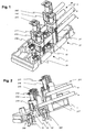
- Fig.1 and Fig.2 is an oblique view of a plug-in module according to the invention with a Isolierstoffmaschine 1 and four connections shown, of which only the two Connections 2.2 'facing the observer and their components with reference numerals are provided.
- 2 shows the insulating body 1 and that seen by the viewer right-hand connector 2 'shown in section.
- connection 2, 2 ' comprises a plug contact 20, 20' and a screw contact 21, 21 ', which are interconnected by means of a hatched contact conductor 22, 22' are permanently electrically connected.
- the cage 210,210 ' forms one in four Sides closed space. The two open sides opposite each other this space define a direction of contact 3. One end of one does not go to the module associated connecting conductor 4,4 'leads parallel to the contact direction 3 in said space.
- the contact bracket 212.212 ' is linearly downwards by means of the screw 216.216' Insulating body 1 moves and clamps the end of the connecting lead 4,4 'between a bottom of the cage 210,210 'and the contact bracket 212,212'.
- the plug contact 20, 20 ' has tulip-shaped profile, and around the contact resistance between it and one To further reduce the busbar is also the spring force of the plug contact 20, 20 'clamping ring 200, 200' provided
- a clip-shaped contact clip 212 according to the invention is shown again in FIG shown separately. Between a contact section 213 and two parallel to it arranged wing ends, the screw is clamped. The two wings are 214 separated by a slot-like recess.
- the contact clip 212 is made of one made of elastic or resilient material so that the two wings 214 for insertion the screw can be bent to the side and then yours shown in Fig.3 Take position again and fix the screw.
- the contact clip 212 furthermore has a lateral tab 215, which connects to the contact section 213 and aligned parallel to the direction of contact 3 outside the cage.
- the associated contact conductor 22, 22 ' is welded to each tab 215, 215'.
- the contact conductor 22, 22 ' is welded to the plug contact 20, 20'.
- Plug-in module as an adapter part of a switching or protection device with additional functions, see above lead the connection conductors to a functional module, not shown in the figures. This can be above or next to the connections, within the same housing unit be arranged.
- the connecting conductors 4, 4 ' are referred to as feed conductors, in this case they lead directly from the feed element without going through a further functional module.
- Their conductor cross-section may be designed for large nominal currents and accordingly quite thick (for example 16 mm 2 for 63 A), so that such feeders cannot be bent easily.
- a feed conductor 4 leading to the rear connection can thus either lead over the front connection or, as shown in FIG. 1, be guided through a suitable tunnel-shaped recess 217 'below the screw contact 21' of the front connection 2 '.
- FIG. 4 shows a feed element, which is formed by an insulating material housing 5 is completed.
- the feeder 4,4 'into the interior of the element is in the the broad or front side of the insulating material housing 5 facing the viewer Opening 50 broken out.
- Insulation housing 5 according to the invention are original, i.e. before they are used, in the area of potential breakthroughs like this prepared that the housing wall there can be easily and irreversibly removed.
- To the edge of the breakthrough points is formed as a perforation or notch or is formed by Prepared for scratching with a pointed object accordingly.
- the feeder will only enter the insulating housing 5 on the same broad side of the housing there the housing wall is opened, while those provided for the same purpose Breakthroughs on the opposite broad side of the housing as cover and Protection against contact remains in place.
- openings 50 become on both broad sides of the housing erupted.
Abstract
Description
- Fig.1
- ein Steckmodul in Schrägaufsicht,
- Fig.2
- ein Steckmodul in Schrägaufsicht, teilweise im Schnitt,
- Fig.3
- einen Kontaktbügel, und
- Fig.4
- ein Steckmodul mit Abdeckung.
- 1
- Isolierstoffkörper
- 2,2'
- Anschluss
- 20,20'
- Steckkontakt
- 200,200'
- Spannring
- 21,21'
- Schraubkontakt
- 210,210'
- Käfig
- 211'
- Gewinde
- 212,212'
- Kontaktbügel
- 213
- Kontaktabschnitt
- 214
- Flügel
- 215
- Lasche
- 216,216'
- Schraube
- 217'
- Ausnehmung
- 22,22'
- Kontaktleiter
- 3
- Kontaktrichtung
- 4,4'
- Anschlussleiter
- 5
- Isolierstoffgehäuse
- 50
- Öffnung
Claims (8)
- Steckmodul für Stecksockelsysteme mit integrierten, parallel angeordneten Stromschienen, umfassend einen elektrisch isolierenden Isolierstoffkörper (1) und mindestens einen ersten und einen zweiten Anschluss (2,2'), wobei jeder Anschluss einen Steckkontakt (20,20') und einen mit diesem elektrisch verbundenen Schraubkontakt (21,21') umfasst, und wobei jeder Steckkontakt (20,20') auf eine Stromschiene aufsteckbar ist und je ein Anschlussleiter (4,4') in einer zumindest annähernd senkrecht zu den Stromschienen liegenden Kontaktrichtung (3) in jeden Schraubkontakt (21,21') einführbar ist,
dadurch gekennzeichnet, dass die Steckkontakte (20,20') und Schraubkontakte (21,21') des ersten und zweiten Anschlusses (2,2') in der Kontaktrichtung (3) auf einer Linie hintereinander angeordnet sind. - Steckmodul nach Anspruch 1 für ein Stecksockelsystem mit mindestens vier Stromschienen für drei Phasen und einen Neutralleiter, wobei das Steckmodul vier Anschlüsse umfasst, dadurch gekennzeichnet, dass jeweils zwei Anschlüsse bezüglich der Kontaktrichtung (3) auf einer Linie hintereinander und versetzt nebeneinander angeordnet sind.
- Steckmodul nach Anspruch 1, wobei das Steckmodul zu einem Einspeiseelement gehört, dadurch gekennzeichnet, dass der Schraubkontakt (21') des zweiten Anschluss (2') bezüglich des Isolierstoffkörpers (1) höher angeordnet ist als der Schraubkontakt (21) des ersten Anschlusses (2), und dass zwischen dem Schraubkontakt (21') des zweiten Anschlusses (2') und dem Isolierstoffkörper (1) eine Ausnehmung (217') für einen Einspeiseleiter (4) des ersten Anschlusses (2) vorgesehen ist.
- Steckmodul nach Anspruch 3, umfassend ein mit dem Isolierstoffkörper (1) verschraubbares Isolierstoffgehäuse (5), dadurch gekennzeichnet, dass das Isolierstoffgehäuse (5) eine Gehäusewand aufweist, welche zur Bildung einer Öffnung (50) als Durchlass für die Speiseleiter (4,4') vorbereitet ist.
- Steckmodul nach einem der vorangehenden Ansprüche, wobei der Schraubkontakt (21) eine Schraube (216), einen Käfig (210) mit Schraubgewinde (211') und einen durch den Käfig (210) geführten, linear beweglichen Bügel umfasst, wobei die Schraube (216) in das Schraubgewinde (211') eingeschraubt ist und durch den Bügel am vollständigen Herausdrehen gehindert wird, dadurch gekennzeichnet, dass der Bügel ein elektrisch leitfähiger Kontaktbügel (212) und der Käfig (210) elektrisch isolierend ist.
- Steckmodul nach Anspruch 5, dadurch gekennzeichnet, dass der Schraubkontakt (21) und der Steckkontakt (20) über einen beweglichen Kontaktleiter (22) elektrisch miteinander verbunden sind.
- Steckmodul nach Anspruch 6, dadurch gekennzeichnet, dass der Kontaktbügel (212) eine parallel zur Kontaktrichtung (3) angeordnete seitliche Lasche (215) aufweist, an welcher der Kontaktleiter (22) angeschweisst ist.
- Steckmodul nach Anspruch 5, dadurch gekennzeichnet, dass der Kontaktbügel (212) aus Federbronze gefertigt ist.
Priority Applications (3)
| Application Number | Priority Date | Filing Date | Title |
|---|---|---|---|
| ES02405178T ES2375470T3 (es) | 2002-03-11 | 2002-03-11 | Módulo de conector para sistema de zócalo de enchufe. |
| EP02405178A EP1351336B1 (de) | 2002-03-11 | 2002-03-11 | Steckmodul für Stecksockelsystem |
| AT02405178T ATE529923T1 (de) | 2002-03-11 | 2002-03-11 | Steckmodul für stecksockelsystem |
Applications Claiming Priority (1)
| Application Number | Priority Date | Filing Date | Title |
|---|---|---|---|
| EP02405178A EP1351336B1 (de) | 2002-03-11 | 2002-03-11 | Steckmodul für Stecksockelsystem |
Publications (2)
| Publication Number | Publication Date |
|---|---|
| EP1351336A1 true EP1351336A1 (de) | 2003-10-08 |
| EP1351336B1 EP1351336B1 (de) | 2011-10-19 |
Family
ID=27838193
Family Applications (1)
| Application Number | Title | Priority Date | Filing Date |
|---|---|---|---|
| EP02405178A Expired - Lifetime EP1351336B1 (de) | 2002-03-11 | 2002-03-11 | Steckmodul für Stecksockelsystem |
Country Status (3)
| Country | Link |
|---|---|
| EP (1) | EP1351336B1 (de) |
| AT (1) | ATE529923T1 (de) |
| ES (1) | ES2375470T3 (de) |
Cited By (5)
| Publication number | Priority date | Publication date | Assignee | Title |
|---|---|---|---|---|
| DE102004043467A1 (de) * | 2004-09-08 | 2006-03-30 | Siemens Ag | Strom-Einspeisemodul |
| DE102004043466B4 (de) * | 2004-09-08 | 2007-08-02 | Siemens Ag | Strom-Einspeisemodul mit Käfig-Zugfederklemmen |
| US10700464B2 (en) | 2016-05-17 | 2020-06-30 | Woehner Gmbh & Co., Kg Elektrotechnische Systeme | Device for a busbar system |
| US11217970B2 (en) | 2017-05-08 | 2022-01-04 | Abb Schweiz Ag | Multiple fed busbar system |
| EP4184732A1 (de) * | 2021-11-22 | 2023-05-24 | Wöhner Besitz GmbH | Stromversorgungsmodul |
Families Citing this family (1)
| Publication number | Priority date | Publication date | Assignee | Title |
|---|---|---|---|---|
| DE102015115197A1 (de) | 2015-09-09 | 2017-03-09 | Eaton Electrical Ip Gmbh & Co. Kg | Anschlussadapter für ein Stromschieneneinspeisesystem |
Citations (3)
| Publication number | Priority date | Publication date | Assignee | Title |
|---|---|---|---|---|
| EP0229590A1 (de) * | 1985-12-14 | 1987-07-22 | CMC Carl Maier + Cie AG | Niederspannungsverteilung |
| US5032092A (en) * | 1989-12-22 | 1991-07-16 | Connection Designs Corporation | Power distribution block |
| FR2786611A1 (fr) * | 1998-11-26 | 2000-06-02 | Jean Jacques Lefebvre | Borne de connexion pour l'alimentation en bouclage d'appareils electriques |
-
2002
- 2002-03-11 EP EP02405178A patent/EP1351336B1/de not_active Expired - Lifetime
- 2002-03-11 ES ES02405178T patent/ES2375470T3/es not_active Expired - Lifetime
- 2002-03-11 AT AT02405178T patent/ATE529923T1/de active
Patent Citations (3)
| Publication number | Priority date | Publication date | Assignee | Title |
|---|---|---|---|---|
| EP0229590A1 (de) * | 1985-12-14 | 1987-07-22 | CMC Carl Maier + Cie AG | Niederspannungsverteilung |
| US5032092A (en) * | 1989-12-22 | 1991-07-16 | Connection Designs Corporation | Power distribution block |
| FR2786611A1 (fr) * | 1998-11-26 | 2000-06-02 | Jean Jacques Lefebvre | Borne de connexion pour l'alimentation en bouclage d'appareils electriques |
Cited By (8)
| Publication number | Priority date | Publication date | Assignee | Title |
|---|---|---|---|---|
| DE102004043467A1 (de) * | 2004-09-08 | 2006-03-30 | Siemens Ag | Strom-Einspeisemodul |
| DE102004043466B4 (de) * | 2004-09-08 | 2007-08-02 | Siemens Ag | Strom-Einspeisemodul mit Käfig-Zugfederklemmen |
| US7604516B2 (en) | 2004-09-08 | 2009-10-20 | Siemens Aktiengesellschaft | Power feeding module |
| US10700464B2 (en) | 2016-05-17 | 2020-06-30 | Woehner Gmbh & Co., Kg Elektrotechnische Systeme | Device for a busbar system |
| US10923850B2 (en) | 2016-05-17 | 2021-02-16 | Woehner Gmbh & Co., Kg Elektrotechnische Systeme | Device for securing an object on a rail |
| US11217970B2 (en) | 2017-05-08 | 2022-01-04 | Abb Schweiz Ag | Multiple fed busbar system |
| EP4184732A1 (de) * | 2021-11-22 | 2023-05-24 | Wöhner Besitz GmbH | Stromversorgungsmodul |
| WO2023088851A1 (en) * | 2021-11-22 | 2023-05-25 | Wöhner Besitz Gmbh | Power supply module |
Also Published As
| Publication number | Publication date |
|---|---|
| ES2375470T3 (es) | 2012-03-01 |
| EP1351336B1 (de) | 2011-10-19 |
| ATE529923T1 (de) | 2011-11-15 |
Similar Documents
| Publication | Publication Date | Title |
|---|---|---|
| DE102006022374B4 (de) | Schaltgerät | |
| DE102007053535B4 (de) | Verbindungsmodul und Einheit aus einem Schaltgerät, einem Verbindungsmodul und einem Adapter | |
| EP1764872B1 (de) | Stromschienenanschlussmodul | |
| EP1818964B1 (de) | Sicherungsleiste mit seitlichen Abgangskontakten und seitlichem Adaptermodul | |
| WO2012163716A1 (de) | Prüf- und anschlussvorrichtungsanordnung und prüfvorrichtung | |
| EP1351336B1 (de) | Steckmodul für Stecksockelsystem | |
| DE2251020B2 (de) | Anschlussvorrichtung | |
| EP1472766B1 (de) | Anschluss- oder verteilvorrichtung für elektrische installationsgeräte | |
| DE102010033112B4 (de) | Elektroinstallationsgerät | |
| DE60119830T2 (de) | Rahmenschenkel für ein Rahmengestell, als Leiter zur Verteilung elektrischer Energie | |
| AT506801A4 (de) | Nh-sicherungsschaltgerät | |
| DE3610451C2 (de) | ||
| EP1638123B1 (de) | Leitungsschutzschalter mit verschiebbarem Steckkontakt | |
| EP1353350B1 (de) | Hilfsschalter | |
| DE3010039A1 (de) | Vorrichtung zum verbinden zweier sammelschienensysteme | |
| EP1251537B1 (de) | Sicherungslasttrennschalter in Leistenbauform | |
| EP1777789A1 (de) | Vormontierte elektrische Installationseinheit | |
| DE10340212B4 (de) | Verteileranordnung | |
| EP1818963B1 (de) | Sicherungsleiste mit seitlichen Abgangskontakten | |
| DE102004058712B4 (de) | Elektrischer Verteilerkasten | |
| DE102018107604A1 (de) | Überspannungsschutzeinrichtung mit mindestens einem Überspannungsschutzgerät, bestehend aus einem Sockelteil und einem mit dem Sockelteil verbindbaren Steckteil | |
| DE2604356C3 (de) | Anschlußvorrichtung für Sicherungsautomaten | |
| EP2874250B1 (de) | Elektrisches Installationsgerät | |
| EP1505701A1 (de) | Auf Stromschienen anzuordnendes elektrischesTeil | |
| WO1999006242A1 (de) | Potentialverteilungssystem zur potentialverteilung an verbraucher sowie geeigneter verbinder |
Legal Events
| Date | Code | Title | Description |
|---|---|---|---|
| PUAI | Public reference made under article 153(3) epc to a published international application that has entered the european phase |
Free format text: ORIGINAL CODE: 0009012 |
|
| AK | Designated contracting states |
Kind code of ref document: A1 Designated state(s): AT BE CH CY DE DK ES FI FR GB GR IE IT LI LU MC NL PT SE TR |
|
| AX | Request for extension of the european patent |
Extension state: AL LT LV MK RO SI |
|
| 17P | Request for examination filed |
Effective date: 20040308 |
|
| AKX | Designation fees paid |
Designated state(s): AT BE CH CY DE DK ES FI FR GB GR IE IT LI LU MC NL PT SE TR |
|
| 17Q | First examination report despatched |
Effective date: 20040525 |
|
| GRAP | Despatch of communication of intention to grant a patent |
Free format text: ORIGINAL CODE: EPIDOSNIGR1 |
|
| GRAS | Grant fee paid |
Free format text: ORIGINAL CODE: EPIDOSNIGR3 |
|
| GRAA | (expected) grant |
Free format text: ORIGINAL CODE: 0009210 |
|
| AK | Designated contracting states |
Kind code of ref document: B1 Designated state(s): AT BE CH CY DE DK ES FI FR GB GR IE IT LI LU MC NL PT SE TR |
|
| REG | Reference to a national code |
Ref country code: GB Ref legal event code: FG4D Free format text: NOT ENGLISH |
|
| REG | Reference to a national code |
Ref country code: CH Ref legal event code: EP |
|
| REG | Reference to a national code |
Ref country code: IE Ref legal event code: FG4D |
|
| REG | Reference to a national code |
Ref country code: DE Ref legal event code: R096 Ref document number: 50215254 Country of ref document: DE Effective date: 20111208 |
|
| REG | Reference to a national code |
Ref country code: NL Ref legal event code: VDEP Effective date: 20111019 |
|
| REG | Reference to a national code |
Ref country code: ES Ref legal event code: FG2A Ref document number: 2375470 Country of ref document: ES Kind code of ref document: T3 Effective date: 20120301 |
|
| REG | Reference to a national code |
Ref country code: IE Ref legal event code: FD4D |
|
| PG25 | Lapsed in a contracting state [announced via postgrant information from national office to epo] |
Ref country code: NL Free format text: LAPSE BECAUSE OF FAILURE TO SUBMIT A TRANSLATION OF THE DESCRIPTION OR TO PAY THE FEE WITHIN THE PRESCRIBED TIME-LIMIT Effective date: 20111019 Ref country code: PT Free format text: LAPSE BECAUSE OF FAILURE TO SUBMIT A TRANSLATION OF THE DESCRIPTION OR TO PAY THE FEE WITHIN THE PRESCRIBED TIME-LIMIT Effective date: 20120220 Ref country code: SE Free format text: LAPSE BECAUSE OF FAILURE TO SUBMIT A TRANSLATION OF THE DESCRIPTION OR TO PAY THE FEE WITHIN THE PRESCRIBED TIME-LIMIT Effective date: 20111019 Ref country code: GR Free format text: LAPSE BECAUSE OF FAILURE TO SUBMIT A TRANSLATION OF THE DESCRIPTION OR TO PAY THE FEE WITHIN THE PRESCRIBED TIME-LIMIT Effective date: 20120120 |
|
| PG25 | Lapsed in a contracting state [announced via postgrant information from national office to epo] |
Ref country code: CY Free format text: LAPSE BECAUSE OF FAILURE TO SUBMIT A TRANSLATION OF THE DESCRIPTION OR TO PAY THE FEE WITHIN THE PRESCRIBED TIME-LIMIT Effective date: 20111019 |
|
| PG25 | Lapsed in a contracting state [announced via postgrant information from national office to epo] |
Ref country code: IE Free format text: LAPSE BECAUSE OF FAILURE TO SUBMIT A TRANSLATION OF THE DESCRIPTION OR TO PAY THE FEE WITHIN THE PRESCRIBED TIME-LIMIT Effective date: 20111019 Ref country code: DK Free format text: LAPSE BECAUSE OF FAILURE TO SUBMIT A TRANSLATION OF THE DESCRIPTION OR TO PAY THE FEE WITHIN THE PRESCRIBED TIME-LIMIT Effective date: 20111019 |
|
| PLBE | No opposition filed within time limit |
Free format text: ORIGINAL CODE: 0009261 |
|
| STAA | Information on the status of an ep patent application or granted ep patent |
Free format text: STATUS: NO OPPOSITION FILED WITHIN TIME LIMIT |
|
| 26N | No opposition filed |
Effective date: 20120720 |
|
| BERE | Be: lapsed |
Owner name: ABB SCHWEIZ A.G. Effective date: 20120331 |
|
| PG25 | Lapsed in a contracting state [announced via postgrant information from national office to epo] |
Ref country code: MC Free format text: LAPSE BECAUSE OF NON-PAYMENT OF DUE FEES Effective date: 20120331 |
|
| REG | Reference to a national code |
Ref country code: CH Ref legal event code: PL |
|
| REG | Reference to a national code |
Ref country code: DE Ref legal event code: R097 Ref document number: 50215254 Country of ref document: DE Effective date: 20120720 |
|
| PG25 | Lapsed in a contracting state [announced via postgrant information from national office to epo] |
Ref country code: BE Free format text: LAPSE BECAUSE OF NON-PAYMENT OF DUE FEES Effective date: 20120331 Ref country code: CH Free format text: LAPSE BECAUSE OF NON-PAYMENT OF DUE FEES Effective date: 20120331 Ref country code: LI Free format text: LAPSE BECAUSE OF NON-PAYMENT OF DUE FEES Effective date: 20120331 |
|
| REG | Reference to a national code |
Ref country code: AT Ref legal event code: MM01 Ref document number: 529923 Country of ref document: AT Kind code of ref document: T Effective date: 20120311 |
|
| PG25 | Lapsed in a contracting state [announced via postgrant information from national office to epo] |
Ref country code: FI Free format text: LAPSE BECAUSE OF FAILURE TO SUBMIT A TRANSLATION OF THE DESCRIPTION OR TO PAY THE FEE WITHIN THE PRESCRIBED TIME-LIMIT Effective date: 20111019 |
|
| PG25 | Lapsed in a contracting state [announced via postgrant information from national office to epo] |
Ref country code: AT Free format text: LAPSE BECAUSE OF NON-PAYMENT OF DUE FEES Effective date: 20120311 |
|
| PG25 | Lapsed in a contracting state [announced via postgrant information from national office to epo] |
Ref country code: TR Free format text: LAPSE BECAUSE OF FAILURE TO SUBMIT A TRANSLATION OF THE DESCRIPTION OR TO PAY THE FEE WITHIN THE PRESCRIBED TIME-LIMIT Effective date: 20111019 |
|
| PG25 | Lapsed in a contracting state [announced via postgrant information from national office to epo] |
Ref country code: LU Free format text: LAPSE BECAUSE OF NON-PAYMENT OF DUE FEES Effective date: 20120311 |
|
| PGFP | Annual fee paid to national office [announced via postgrant information from national office to epo] |
Ref country code: ES Payment date: 20150326 Year of fee payment: 14 |
|
| PGFP | Annual fee paid to national office [announced via postgrant information from national office to epo] |
Ref country code: GB Payment date: 20150319 Year of fee payment: 14 |
|
| REG | Reference to a national code |
Ref country code: FR Ref legal event code: PLFP Year of fee payment: 15 |
|
| GBPC | Gb: european patent ceased through non-payment of renewal fee |
Effective date: 20160311 |
|
| PG25 | Lapsed in a contracting state [announced via postgrant information from national office to epo] |
Ref country code: GB Free format text: LAPSE BECAUSE OF NON-PAYMENT OF DUE FEES Effective date: 20160311 |
|
| REG | Reference to a national code |
Ref country code: FR Ref legal event code: PLFP Year of fee payment: 16 |
|
| REG | Reference to a national code |
Ref country code: FR Ref legal event code: PLFP Year of fee payment: 17 |
|
| PG25 | Lapsed in a contracting state [announced via postgrant information from national office to epo] |
Ref country code: ES Free format text: LAPSE BECAUSE OF NON-PAYMENT OF DUE FEES Effective date: 20160312 |
|
| REG | Reference to a national code |
Ref country code: ES Ref legal event code: FD2A Effective date: 20181205 |
|
| PGFP | Annual fee paid to national office [announced via postgrant information from national office to epo] |
Ref country code: FR Payment date: 20210323 Year of fee payment: 20 Ref country code: IT Payment date: 20210329 Year of fee payment: 20 |
|
| PGFP | Annual fee paid to national office [announced via postgrant information from national office to epo] |
Ref country code: DE Payment date: 20210319 Year of fee payment: 20 |
|
| REG | Reference to a national code |
Ref country code: DE Ref legal event code: R071 Ref document number: 50215254 Country of ref document: DE |