EP1351238A1 - Method for frame addressing in a sector - Google Patents
Method for frame addressing in a sector Download PDFInfo
- Publication number
- EP1351238A1 EP1351238A1 EP02007715A EP02007715A EP1351238A1 EP 1351238 A1 EP1351238 A1 EP 1351238A1 EP 02007715 A EP02007715 A EP 02007715A EP 02007715 A EP02007715 A EP 02007715A EP 1351238 A1 EP1351238 A1 EP 1351238A1
- Authority
- EP
- European Patent Office
- Prior art keywords
- valid
- pattern
- frame
- synchronisation
- codes
- Prior art date
- Legal status (The legal status is an assumption and is not a legal conclusion. Google has not performed a legal analysis and makes no representation as to the accuracy of the status listed.)
- Withdrawn
Links
Images
Classifications
-
- G—PHYSICS
- G11—INFORMATION STORAGE
- G11B—INFORMATION STORAGE BASED ON RELATIVE MOVEMENT BETWEEN RECORD CARRIER AND TRANSDUCER
- G11B7/00—Recording or reproducing by optical means, e.g. recording using a thermal beam of optical radiation by modifying optical properties or the physical structure, reproducing using an optical beam at lower power by sensing optical properties; Record carriers therefor
- G11B7/007—Arrangement of the information on the record carrier, e.g. form of tracks, actual track shape, e.g. wobbled, or cross-section, e.g. v-shaped; Sequential information structures, e.g. sectoring or header formats within a track
-
- G—PHYSICS
- G11—INFORMATION STORAGE
- G11B—INFORMATION STORAGE BASED ON RELATIVE MOVEMENT BETWEEN RECORD CARRIER AND TRANSDUCER
- G11B20/00—Signal processing not specific to the method of recording or reproducing; Circuits therefor
- G11B20/10—Digital recording or reproducing
- G11B20/14—Digital recording or reproducing using self-clocking codes
- G11B20/1403—Digital recording or reproducing using self-clocking codes characterised by the use of two levels
-
- G—PHYSICS
- G11—INFORMATION STORAGE
- G11B—INFORMATION STORAGE BASED ON RELATIVE MOVEMENT BETWEEN RECORD CARRIER AND TRANSDUCER
- G11B20/00—Signal processing not specific to the method of recording or reproducing; Circuits therefor
- G11B20/10—Digital recording or reproducing
-
- G—PHYSICS
- G11—INFORMATION STORAGE
- G11B—INFORMATION STORAGE BASED ON RELATIVE MOVEMENT BETWEEN RECORD CARRIER AND TRANSDUCER
- G11B20/00—Signal processing not specific to the method of recording or reproducing; Circuits therefor
- G11B20/10—Digital recording or reproducing
- G11B20/10009—Improvement or modification of read or write signals
- G11B20/10046—Improvement or modification of read or write signals filtering or equalising, e.g. setting the tap weights of an FIR filter
- G11B20/10212—Improvement or modification of read or write signals filtering or equalising, e.g. setting the tap weights of an FIR filter compensation for data shift, e.g. pulse-crowding effects
-
- G—PHYSICS
- G11—INFORMATION STORAGE
- G11B—INFORMATION STORAGE BASED ON RELATIVE MOVEMENT BETWEEN RECORD CARRIER AND TRANSDUCER
- G11B20/00—Signal processing not specific to the method of recording or reproducing; Circuits therefor
- G11B20/10—Digital recording or reproducing
- G11B20/10009—Improvement or modification of read or write signals
- G11B20/10305—Improvement or modification of read or write signals signal quality assessment
- G11B20/10398—Improvement or modification of read or write signals signal quality assessment jitter, timing deviations or phase and frequency errors
- G11B20/10425—Improvement or modification of read or write signals signal quality assessment jitter, timing deviations or phase and frequency errors by counting out-of-lock events of a PLL
-
- G—PHYSICS
- G11—INFORMATION STORAGE
- G11B—INFORMATION STORAGE BASED ON RELATIVE MOVEMENT BETWEEN RECORD CARRIER AND TRANSDUCER
- G11B20/00—Signal processing not specific to the method of recording or reproducing; Circuits therefor
- G11B20/10—Digital recording or reproducing
- G11B20/14—Digital recording or reproducing using self-clocking codes
-
- G—PHYSICS
- G11—INFORMATION STORAGE
- G11B—INFORMATION STORAGE BASED ON RELATIVE MOVEMENT BETWEEN RECORD CARRIER AND TRANSDUCER
- G11B27/00—Editing; Indexing; Addressing; Timing or synchronising; Monitoring; Measuring tape travel
- G11B27/10—Indexing; Addressing; Timing or synchronising; Measuring tape travel
-
- G—PHYSICS
- G11—INFORMATION STORAGE
- G11B—INFORMATION STORAGE BASED ON RELATIVE MOVEMENT BETWEEN RECORD CARRIER AND TRANSDUCER
- G11B27/00—Editing; Indexing; Addressing; Timing or synchronising; Monitoring; Measuring tape travel
- G11B27/10—Indexing; Addressing; Timing or synchronising; Measuring tape travel
- G11B27/19—Indexing; Addressing; Timing or synchronising; Measuring tape travel by using information detectable on the record carrier
- G11B27/28—Indexing; Addressing; Timing or synchronising; Measuring tape travel by using information detectable on the record carrier by using information signals recorded by the same method as the main recording
- G11B27/30—Indexing; Addressing; Timing or synchronising; Measuring tape travel by using information detectable on the record carrier by using information signals recorded by the same method as the main recording on the same track as the main recording
- G11B27/3027—Indexing; Addressing; Timing or synchronising; Measuring tape travel by using information detectable on the record carrier by using information signals recorded by the same method as the main recording on the same track as the main recording used signal is digitally coded
-
- G—PHYSICS
- G11—INFORMATION STORAGE
- G11B—INFORMATION STORAGE BASED ON RELATIVE MOVEMENT BETWEEN RECORD CARRIER AND TRANSDUCER
- G11B20/00—Signal processing not specific to the method of recording or reproducing; Circuits therefor
- G11B20/10—Digital recording or reproducing
- G11B2020/10935—Digital recording or reproducing wherein a time constraint must be met
- G11B2020/10972—Management of interruptions, e.g. due to editing
-
- G—PHYSICS
- G11—INFORMATION STORAGE
- G11B—INFORMATION STORAGE BASED ON RELATIVE MOVEMENT BETWEEN RECORD CARRIER AND TRANSDUCER
- G11B20/00—Signal processing not specific to the method of recording or reproducing; Circuits therefor
- G11B20/10—Digital recording or reproducing
- G11B20/12—Formatting, e.g. arrangement of data block or words on the record carriers
- G11B2020/1264—Formatting, e.g. arrangement of data block or words on the record carriers wherein the formatting concerns a specific kind of data
- G11B2020/1265—Control data, system data or management information, i.e. data used to access or process user data
- G11B2020/1287—Synchronisation pattern, e.g. VCO fields
-
- G—PHYSICS
- G11—INFORMATION STORAGE
- G11B—INFORMATION STORAGE BASED ON RELATIVE MOVEMENT BETWEEN RECORD CARRIER AND TRANSDUCER
- G11B2220/00—Record carriers by type
- G11B2220/20—Disc-shaped record carriers
- G11B2220/25—Disc-shaped record carriers characterised in that the disc is based on a specific recording technology
- G11B2220/2537—Optical discs
- G11B2220/2545—CDs
-
- G—PHYSICS
- G11—INFORMATION STORAGE
- G11B—INFORMATION STORAGE BASED ON RELATIVE MOVEMENT BETWEEN RECORD CARRIER AND TRANSDUCER
- G11B2220/00—Record carriers by type
- G11B2220/20—Disc-shaped record carriers
- G11B2220/25—Disc-shaped record carriers characterised in that the disc is based on a specific recording technology
- G11B2220/2537—Optical discs
- G11B2220/2562—DVDs [digital versatile discs]; Digital video discs; MMCDs; HDCDs
Definitions
- the present invention relates to a method for determining the address of a frame inside a data sector of an optical recording medium, the sector comprising a plurality of frames, each frame being preceded by a synchronization code, and an apparatus for reading from and/or writing to optical recording media using such method.
- Data stored on optical recording media like DVD (digital video or versatile disk) or SACD (super audio compact disk) consists of a plurality of physical sectors. Each sector consists of 26 frames of a length of 91 data bytes each. Every frame is preceded by one of eight types of synchronisation codes SY0...SY7 that do not occur in the 16/8 modulation used for encoding the data on the recording medium. These synchronization codes are located in the sector in the following pattern: The sequence of syncs through a sector is thus: 0 5 1 5 2 5 3 5 4 5 1 6 2 6 3 6 4 6 1 7 2 7 3 7 4 7
- decoders for decoding the data stored on the recording medium can easily synchronize their timing or re-synchronise after clock loss.
- phase-locked loop (PLL) based acquisition system During playback of optical recording media, different kinds of defects can occur, causing problems to the phase-locked loop (PLL) based acquisition system. If a defect occurs which can be detected by a disturbance detector (e.g. a black dot or a silver dot), the PLL is frozen and the correct number of frames is inserted. If, however, the defect cannot be detected by the disturbance detector (e.g. an interruption), the PLL can drift away and an incorrect number of frames is inserted. This problem is inherent to a PLL-based acquisition system and causes streaming loss until the start of the next sector. The same happens when a synchronisation code is inserted or a wrong synchronisation code is detected.
- a disturbance detector e.g. a black dot or a silver dot
- the PLL is frozen and the correct number of frames is inserted. If, however, the defect cannot be detected by the disturbance detector (e.g. an interruption), the PLL can drift away and an incorrect number of frames is inserted.
- An object of the present invention is, therefore, to propose a method for determining the address of a frame inside a data sector of an optical recording medium that is robust against streaming loss. It is another object of the present invention to propose an apparatus for reading from and/or writing to optical recording media using such method.
- a method for determining the address of a frame inside a data sector of an optical recording medium comprises the steps of:
- the corresponding 3-bit sync number 0...7 is appended to the history of previously detected synchronisation codes.
- the pattern of the last synchronisation codes is then compared with a plurality of valid patterns, i.e. patterns corresponding to the different frame addresses. If the comparison gives a valid pattern, the corresponding frame address is found and outputted. If a synchronisation code is inserted or an unexpected synchronisation code is used, the pattern of the last synchronisation codes will not correspond to a valid pattern. An error frame address will then be delivered. As soon as the next valid pattern of the last synchronisation codes is found, the next valid frame address is delivered, i.e. streaming loss is recovered still within the sector.
- the history of previously detected synchronisation codes, the pattern of the last synchronisation codes and the valid patterns of synchronization codes each comprise four synchronisation codes.
- the valid frame address is found with high security while at the same time the effort necessary for the comparison of the patterns is kept low.
- the security is reduced, while with more synchronisation codes the effort for comparison of the patterns increases.
- the method according to the invention further comprises the steps of:
- Resetting the history of synchronisation codes to zero prevents that two successive wrong synchronisation codes are kept in the history. Otherwise in combination these wrong synchronisation codes could give a valid pattern and thus a bad frame address. Enabling the reset protection prevents more resets before the next valid pattern of synchronisation codes has been detected. Without the reset protection after the first reset no more valid patterns could be detected.
- the history of previously detected synchronisation codes is kept in a shift register. In this way only a small number of previously detected synchronisation codes has to be stored.
- a synchronisation code is detected, it is placed in the first slot of the shift register, pushing all previous synchronisation codes by one slot.
- the valid patterns of synchronisation codes are stored in a table. This allows for fast comparison of the pattern of the last synchronisation codes with the valid patterns.
- the error frame address is one of a plurality of predefined frame addresses depending on the last valid frame address.
- two predefined frame addresses are used, both lying outside the range of valid frame addresses.
- a device for determining the address of a frame inside a data sector of an optical recording medium comprises means for keeping a history of previously detected synchronisation codes, means for appending the detected synchronisation code to the history, a comparator for comparing a pattern of the last synchronisation codes with valid patterns of synchronisation codes, the valid patterns corresponding to the different frame addresses, and an output for delivering a frame address of the current frame.
- Such a device has the advantage that it allows recovery of streaming loss still within the sector where the streaming loss occurred. Streaming loss is recovered quickly and with a high degree of certainty.
- the delivered frame address is a valid frame address if the pattern of the last synchronisation codes corresponds to a valid pattern, and an error frame address otherwise. This allows for a secure discrimination between valid and invalid frame addresses.
- the means for keeping the history of previously detected synchronisation codes is a shift register. This has the advantage that only a small number of synchronisation codes has to be stored, making storage inexpensive.
- the error frame address is one of a plurality of predefined frame addresses depending on the last valid frame address. If two predefined frame addresses are used alternatingly, both frame addresses lying outside the range of valid frame addresses, correct row addressing is achieved. For that purpose the row number is obtained from the four most significant bits of the previous valid or error frame address and a signal indicating the next row is obtained from the inverted least significant bit of the previous valid or error frame address.
- the device further comprises a table for storing the valid patterns of synchronization codes. This allows a fast comparison of the pattern of the last synchronisation codes with the valid patterns.
- an apparatus for reading from and/or writing to optical recording media uses a method or comprises a device according to the invention for frame addressing.
- Such an apparatus is capable of recovering streaming loss still within the sector where a streaming loss occurred. Therefore, during playback data which has been read correctly is not written to a wrong position. This is remedient for decoding, since it gives the error correction more capacity to correct other errors, resulting in an overall improved performance.
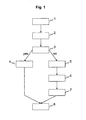
- Fig. 1 schematically shows a flowchart of a method according to the invention.
- a synchronization code is detected. If the synchronisation code is used, the corresponding sync number is pushed in a step 2 into a four-step shift register.
- the pattern of the four sync numbers stored in the shift register is compared with valid patterns of sync numbers. If the pattern is a valid pattern; in a step 4 the corresponding frame address is found. This frame address is then output in a step 8. If, on the other hand, the pattern stored in the shift register does not correspond to a valid pattern, in a step 5 the values in the shift register are reset to zero.
- a reset protection is enabled. Then one of two possible error frame address is determined depending on the last valid frame address. This error frame address is outputted in the step 8.
- the frame address output will thus provide a continuous zero to 25-frame address for correct data. If a defect occurs which can be detected by a disturbance detector (e.g. a black dot or a silver dot), the PLL is frozen and the correct number of frames is inserted. If a defect occurs which cannot be detected by the disturbance detector (e.g. an interruption), the PLL can drift away and a wrong number of frames can be inserted during the defect. The first valid frame address will then re-synchronise the frame addressing.
- a disturbance detector e.g. a black dot or a silver dot
- shift register 'real' frame frame address SY[3] SY[2] SY[1] SY[0] 11 11 4 5 1 6 12 12 5 1 6 2 13 defective 31 0 0 0 0 14 30 0 0 0 3 15 31 0 0 3 6 16 30 0 3 6 4 17 17 3 6 4 6 18 18 6 4 6 1
- row addressing To achieve row addressing the row number is obtained from the four most significant bits of the frame address and a signal indicating the next row is obtained from the inverted least significant bit of the frame address.
- shift register 'real' frame frame address SY[3] SY[2] SY[1] SY[0] next row row 11 11 4 5 1 6 0 12 12 5 1 6 2 1 6 13 defective 31 0 0 0 0 14 30 0 0 0 3 1 15 15 31 0 0 3 6 0 16 30 0 3 6 4 1 15 17 17 3 6 4 6 0 18 18 6 4 6 1 1 9
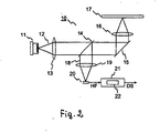
- Fig. 2 schematically depicts an apparatus 10 for reading from and/or writing to optical recording media 17 comprising a device 22 according to the invention.
- a laser diode 11 emits a light beam 12, which is collimated by a collimating lens 13.
- the collimated light beam 12 passes a semi-transparent mirror 14 and is directed by a mirror 15 to a focussing lens 16, which focuses the light beam 12 onto the track of an optical recording medium 17.
- the optical recording medium 17 reflects part of the light, which is modulated according to the information stored in the track of the optical recording medium 17.
- the reflected light is collimated by the focusing lens 16 and directed by the mirror 15 to the semi-transparent mirror 14.
- the semi-transparent mirror 14 deflects part of the returning light beam 18 to a further focusing lens 19, which focuses the returning light beam 18 on a photodetector 20.
- the photodetector 20 allows to detect the modulation contained in the returning light beam 18 and, therefore, to recover the information stored in the track of the optical recording medium 17, which is output as a data signal HF.
- the photodetector 20 may comprise a plurality of detector elements to generate tracking and focusing error signals used for tracking and focusing besides the data signal HF.
- the data signal HF is input into a data acquisition system 21 comprising a device 22 according to the invention.
- the data acquisition system 21 outputs a data stream DS.
- the data acquisition system 21 performs frame insertion if defects are detected.
- recovery of the streaming loss is achieved using the device 22.
Landscapes
- Engineering & Computer Science (AREA)
- Signal Processing (AREA)
- Signal Processing For Digital Recording And Reproducing (AREA)
- Optical Recording Or Reproduction (AREA)
Abstract
The present invention relates to a method for determining the
address of a frame inside a data sector of an optical recording
medium (17), the sector comprising a plurality of frames, each
frame being preceded by a synchronization code, and an
apparatus (10) for reading from and/or writing to optical
recording media (17) using such method.
It is an object of the present invention to propose a method
for determining the address of a frame inside a data sector of
an optical recording medium (17) that is robust against
streaming loss. It is another object of the present invention
to propose an apparatus (10) for reading from and/or writing to
optical recording media (17) using such method.
According to the invention, the method comprises the steps of:
- keeping a history of previously detected synchronization codes;
- appending (2) the detected synchronization code to the history;
- comparing (3) a pattern of the last synchronisation codes with a plurality of valid patterns of synchronization codes;
- delivering (4) a valid frame address if the pattern corresponds to a valid pattern, the frame address corresponding to the valid pattern, and
- delivering (7) an error frame address if the pattern does not correspond to a valid pattern.
Description
- The present invention relates to a method for determining the address of a frame inside a data sector of an optical recording medium, the sector comprising a plurality of frames, each frame being preceded by a synchronization code, and an apparatus for reading from and/or writing to optical recording media using such method.
- Data stored on optical recording media like DVD (digital video or versatile disk) or SACD (super audio compact disk) consists of a plurality of physical sectors. Each sector consists of 26 frames of a length of 91 data bytes each. Every frame is preceded by one of eight types of synchronisation codes SY0...SY7 that do not occur in the 16/8 modulation used for encoding the data on the recording medium. These synchronization codes are located in the sector in the following pattern:The sequence of syncs through a sector is thus:

0 5 1 5 2 5 3 5 4 5 1 6 2 6 3 6 4 6 1 7 2 7 3 7 4 7 - Due to the special arrangement of the synchronization codes, decoders for decoding the data stored on the recording medium can easily synchronize their timing or re-synchronise after clock loss.
- During playback of optical recording media, different kinds of defects can occur, causing problems to the phase-locked loop (PLL) based acquisition system. If a defect occurs which can be detected by a disturbance detector (e.g. a black dot or a silver dot), the PLL is frozen and the correct number of frames is inserted. If, however, the defect cannot be detected by the disturbance detector (e.g. an interruption), the PLL can drift away and an incorrect number of frames is inserted. This problem is inherent to a PLL-based acquisition system and causes streaming loss until the start of the next sector. The same happens when a synchronisation code is inserted or a wrong synchronisation code is detected.
- An object of the present invention is, therefore, to propose a method for determining the address of a frame inside a data sector of an optical recording medium that is robust against streaming loss. It is another object of the present invention to propose an apparatus for reading from and/or writing to optical recording media using such method.
- According to the invention, a method for determining the address of a frame inside a data sector of an optical recording medium, the sector comprising a plurality of frames, each frame being preceded by a synchronization code which is detected during playback of the optical recording medium, comprises the steps of:
- keeping a history of previously detected synchronization codes;
- appending the detected synchronization code to the history;
- comparing a pattern of the last synchronisation codes with a plurality of valid patterns of synchronization codes;
- delivering a valid frame address if the pattern corresponds to a valid pattern, the frame address corresponding to the valid pattern, and
- delivering an error frame address if the pattern does not correspond to a valid pattern.
- When a synchronization code is detected during playback, the corresponding 3-bit sync number 0...7 is appended to the history of previously detected synchronisation codes. The pattern of the last synchronisation codes is then compared with a plurality of valid patterns, i.e. patterns corresponding to the different frame addresses. If the comparison gives a valid pattern, the corresponding frame address is found and outputted. If a synchronisation code is inserted or an unexpected synchronisation code is used, the pattern of the last synchronisation codes will not correspond to a valid pattern. An error frame address will then be delivered. As soon as the next valid pattern of the last synchronisation codes is found, the next valid frame address is delivered, i.e. streaming loss is recovered still within the sector.
- Advantageously, the history of previously detected synchronisation codes, the pattern of the last synchronisation codes and the valid patterns of synchronization codes each comprise four synchronisation codes. In this way the valid frame address is found with high security while at the same time the effort necessary for the comparison of the patterns is kept low. Of course, it is also possible to use less than four or more than four synchronisation codes for comparison of the patterns. However, with less synchronisation codes the security is reduced, while with more synchronisation codes the effort for comparison of the patterns increases.
- Favourably, the method according to the invention further comprises the steps of:
- resetting the synchronisation codes kept in the history to zero if the pattern of the last synchronisation codes does not correspond to a valid pattern;
- enabling a reset protection for the history after resetting; and
- disabling the reset protection the next time the pattern of the last synchronisation codes corresponds to a valid pattern.
- Resetting the history of synchronisation codes to zero prevents that two successive wrong synchronisation codes are kept in the history. Otherwise in combination these wrong synchronisation codes could give a valid pattern and thus a bad frame address. Enabling the reset protection prevents more resets before the next valid pattern of synchronisation codes has been detected. Without the reset protection after the first reset no more valid patterns could be detected.
- According to the invention, the history of previously detected synchronisation codes is kept in a shift register. In this way only a small number of previously detected synchronisation codes has to be stored. When a synchronisation code is detected, it is placed in the first slot of the shift register, pushing all previous synchronisation codes by one slot.
- Advantageously, the valid patterns of synchronisation codes are stored in a table. This allows for fast comparison of the pattern of the last synchronisation codes with the valid patterns.
- According to the invention, the error frame address is one of a plurality of predefined frame addresses depending on the last valid frame address. Advantageously, two predefined frame addresses are used, both lying outside the range of valid frame addresses. By using the two frame addresses alternatingly, correct row addressing is achieved. For that purpose the row number is obtained from the four most significant bits of the previous valid or error frame address and a signal indicating the next row is obtained from the inverted least significant bit of the previous valid or error frame address.
- According to another aspect of the invention, a device for determining the address of a frame inside a data sector of an optical recording medium, the sector comprising a plurality of frames, each frame being preceded by a synchronization code which is detected during playback of the optical recording medium, comprises means for keeping a history of previously detected synchronisation codes, means for appending the detected synchronisation code to the history, a comparator for comparing a pattern of the last synchronisation codes with valid patterns of synchronisation codes, the valid patterns corresponding to the different frame addresses, and an output for delivering a frame address of the current frame.
- Such a device has the advantage that it allows recovery of streaming loss still within the sector where the streaming loss occurred. Streaming loss is recovered quickly and with a high degree of certainty.
- Advantageously, the delivered frame address is a valid frame address if the pattern of the last synchronisation codes corresponds to a valid pattern, and an error frame address otherwise. This allows for a secure discrimination between valid and invalid frame addresses.
- Favourably, the means for keeping the history of previously detected synchronisation codes is a shift register. This has the advantage that only a small number of synchronisation codes has to be stored, making storage inexpensive.
- According to the invention, the error frame address is one of a plurality of predefined frame addresses depending on the last valid frame address. If two predefined frame addresses are used alternatingly, both frame addresses lying outside the range of valid frame addresses, correct row addressing is achieved. For that purpose the row number is obtained from the four most significant bits of the previous valid or error frame address and a signal indicating the next row is obtained from the inverted least significant bit of the previous valid or error frame address.
- Favourably, the device further comprises a table for storing the valid patterns of synchronization codes. This allows a fast comparison of the pattern of the last synchronisation codes with the valid patterns.
- According to another aspect of the invention, an apparatus for reading from and/or writing to optical recording media uses a method or comprises a device according to the invention for frame addressing. Such an apparatus is capable of recovering streaming loss still within the sector where a streaming loss occurred. Therefore, during playback data which has been read correctly is not written to a wrong position. This is beneficent for decoding, since it gives the error correction more capacity to correct other errors, resulting in an overall improved performance.
- An exemplary embodiment of the invention is specified in the following description of an advantageous method with reference to the figures. It is understood that the invention is not limited to this exemplary embodiment and that the specified features can also expediently be combined and/or modified without departing from the scope of the present invention. In the figures:
- Fig. 1
- shows a flowchart of method according to the invention; and
- Fig. 2
- shows an apparatus for reading from and/or writing to optical recording media comprising a device according to the invention.
- Fig. 1 schematically shows a flowchart of a method according to the invention. When data is played back from an
optical recording medium 17, in a step 1 a synchronization code is detected. If the synchronisation code is used, the corresponding sync number is pushed in a step 2 into a four-step shift register. In astep 3 the pattern of the four sync numbers stored in the shift register is compared with valid patterns of sync numbers. If the pattern is a valid pattern; in a step 4 the corresponding frame address is found. This frame address is then output in astep 8. If, on the other hand, the pattern stored in the shift register does not correspond to a valid pattern, in a step 5 the values in the shift register are reset to zero. To prevent further resets until the next valid pattern of synchronisation codes is found, in a step 6 a reset protection is enabled. Then one of two possible error frame address is determined depending on the last valid frame address. This error frame address is outputted in thestep 8. The frame address output will thus provide a continuous zero to 25-frame address for correct data. If a defect occurs which can be detected by a disturbance detector (e.g. a black dot or a silver dot), the PLL is frozen and the correct number of frames is inserted. If a defect occurs which cannot be detected by the disturbance detector (e.g. an interruption), the PLL can drift away and a wrong number of frames can be inserted during the defect. The first valid frame address will then re-synchronise the frame addressing. For better understanding an example is shown below, using 30 and 31 as error frame addresses:shift register 'real' frame frame address SY[3] SY[2] SY[1] SY[0] 11 11 4 5 1 6 12 12 5 1 6 2 13 defective 31 0 0 0 0 14 30 0 0 0 3 15 31 0 0 3 6 16 30 0 3 6 4 17 17 3 6 4 6 18 18 6 4 6 1 - To achieve row addressing the row number is obtained from the four most significant bits of the frame address and a signal indicating the next row is obtained from the inverted least significant bit of the frame address. The derivation of row addressing is shown below using the above example:
shift register 'real' frame frame address SY[3] SY[2] SY[1] SY[0] next row row 11 11 4 5 1 6 0 12 12 5 1 6 2 1 6 13 defective 31 0 0 0 0 0 14 30 0 0 0 3 1 15 15 31 0 0 3 6 0 16 30 0 3 6 4 1 15 17 17 3 6 4 6 0 18 18 6 4 6 1 1 9 - Fig. 2 schematically depicts an
apparatus 10 for reading from and/or writing tooptical recording media 17 comprising adevice 22 according to the invention. Alaser diode 11 emits alight beam 12, which is collimated by a collimatinglens 13. The collimatedlight beam 12 passes asemi-transparent mirror 14 and is directed by amirror 15 to a focussinglens 16, which focuses thelight beam 12 onto the track of anoptical recording medium 17. Theoptical recording medium 17 reflects part of the light, which is modulated according to the information stored in the track of theoptical recording medium 17. The reflected light is collimated by the focusinglens 16 and directed by themirror 15 to thesemi-transparent mirror 14. Thesemi-transparent mirror 14 deflects part of the returninglight beam 18 to a further focusinglens 19, which focuses the returninglight beam 18 on aphotodetector 20. Thephotodetector 20 allows to detect the modulation contained in the returninglight beam 18 and, therefore, to recover the information stored in the track of theoptical recording medium 17, which is output as a data signal HF. Thephotodetector 20 may comprise a plurality of detector elements to generate tracking and focusing error signals used for tracking and focusing besides the data signal HF. The data signal HF is input into adata acquisition system 21 comprising adevice 22 according to the invention. Thedata acquisition system 21 outputs a data stream DS. For that purpose, thedata acquisition system 21 performs frame insertion if defects are detected. In addition, if streaming loss occurs due to non-detectable defects, recovery of the streaming loss is achieved using thedevice 22.
Claims (12)
- Method for determining the address of a frame inside a data sector of an optical recording medium (17), the sector comprising a plurality of frames, each frame being preceded by a synchronisation code which is detected (1) during playback of the optical recording medium (17), the method comprising the steps of:keeping a history of previously detected synchronisation codes;appending (2) the detected synchronisation code to the history;comparing (3) a pattern of the last synchronisation codes with a plurality of valid patterns of synchronisation codes;delivering (4) a valid frame address if the pattern corresponds to a valid pattern, the frame address corresponding to the valid pattern; anddelivering (7) an error frame address if the pattern does not correspond to a valid pattern.
- Method according to claim 1, characterized in that the history of previously detected synchronisation codes, the pattern of the last synchronisation codes and the valid patterns of synchronisation codes each comprise four synchronisation codes.
- Method according to one of claims 1 or 2, further comprising the steps of:resetting (5) the history to zero if the pattern of the last synchronisation codes does not correspond to a valid pattern;enabling (6) a reset protection for the history after resetting; anddisabling the reset protection the next time the pattern of the last synchronisation codes corresponds to a valid pattern.
- Method according to one of claims 1-3, characterized in that the history of previously detected synchronisation codes is kept in a shift register.
- Method according to one of claims 1-4, characterized in that the valid patterns of synchronisation codes are stored in a table.
- Method according to one of claims 1-5, characterized in that the error frame address is one of a plurality of predefined frame addresses depending on the last valid frame address.
- Device for determining the address of a frame inside a data sector of an optical recording medium (17), the sector comprising a plurality of frames, each frame being preceded by a synchronisation code which is detected during playback of the optical recording medium (17), characterized in that it comprises means for keeping a history of previously detected synchronisation codes, means for appending the detected synchronisation code to the history, a comparator for comparing a pattern of the last synchronisation codes with valid patterns of synchronisation codes, the valid patterns corresponding to the different frame addresses, and an output for delivering a frame address of the current frame.
- Device according to claim 7, characterized in that the delivered frame address is a valid frame address if the pattern of the last synchronisation codes corresponds to a valid pattern of synchronisation codes, and an error frame address otherwise.
- Device according to claim 8, characterized in that the means for keeping the history of previously detected synchronisation codes is a shift register.
- Device according to one of claims 8 or 9, characterized in that the error frame address is one of a plurality of predefined frame addresses depending on the last valid frame address.
- Device according to one of claims 7-10, characterized in that it further comprises a table for storing the valid patterns of synchronisation codes.
- Apparatus for reading from and/or writing to optical recording media (17), characterized in that it uses a method according to one of claims 1-6 or comprises a device according to one of claims 7-11 for frame addressing.
Priority Applications (7)
| Application Number | Priority Date | Filing Date | Title |
|---|---|---|---|
| EP02007715A EP1351238A1 (en) | 2002-04-05 | 2002-04-05 | Method for frame addressing in a sector |
| KR10-2003-0015776A KR20030080198A (en) | 2002-04-05 | 2003-03-13 | Method for in-sector data management in frame addressing |
| EP03006515A EP1351239A1 (en) | 2002-04-05 | 2003-03-22 | Method for in-sector data management in frame addressing |
| CNB03107927XA CN100452223C (en) | 2002-04-05 | 2003-03-25 | Method of Area Data Management in Screen Addressing |
| JP2003099143A JP4325255B2 (en) | 2002-04-05 | 2003-04-02 | Method for intra-sector data management in frame addressing |
| US10/405,552 US7345978B2 (en) | 2002-04-05 | 2003-04-02 | Method for in-sector data management in frame addressing |
| TW092107677A TWI223148B (en) | 2002-04-05 | 2003-04-04 | Method for in-sector data management in frame addressing |
Applications Claiming Priority (1)
| Application Number | Priority Date | Filing Date | Title |
|---|---|---|---|
| EP02007715A EP1351238A1 (en) | 2002-04-05 | 2002-04-05 | Method for frame addressing in a sector |
Publications (1)
| Publication Number | Publication Date |
|---|---|
| EP1351238A1 true EP1351238A1 (en) | 2003-10-08 |
Family
ID=27838076
Family Applications (1)
| Application Number | Title | Priority Date | Filing Date |
|---|---|---|---|
| EP02007715A Withdrawn EP1351238A1 (en) | 2002-04-05 | 2002-04-05 | Method for frame addressing in a sector |
Country Status (6)
| Country | Link |
|---|---|
| US (1) | US7345978B2 (en) |
| EP (1) | EP1351238A1 (en) |
| JP (1) | JP4325255B2 (en) |
| KR (1) | KR20030080198A (en) |
| CN (1) | CN100452223C (en) |
| TW (1) | TWI223148B (en) |
Citations (3)
| Publication number | Priority date | Publication date | Assignee | Title |
|---|---|---|---|---|
| EP0820062A2 (en) * | 1996-07-15 | 1998-01-21 | Sony Corporation | Storage medium reproduction apparatus and method |
| EP0820063A2 (en) * | 1996-07-18 | 1998-01-21 | Sony Corporation | Playback device and method, and recording device and method |
| US6041029A (en) * | 1997-02-28 | 2000-03-21 | Sony Corporation | Disc apparatus |
Family Cites Families (5)
| Publication number | Priority date | Publication date | Assignee | Title |
|---|---|---|---|---|
| JPH07307731A (en) * | 1994-05-11 | 1995-11-21 | Oki Electric Ind Co Ltd | Detecting circuit for frame synchronization pattern |
| JP3814966B2 (en) * | 1997-08-14 | 2006-08-30 | ソニー株式会社 | RECORDING MEDIUM, DATA TRANSMISSION DEVICE, DATA RECEPTION DEVICE, AND OPTICAL DISK DEVICE |
| JPH11176081A (en) * | 1997-12-08 | 1999-07-02 | Matsushita Electric Ind Co Ltd | Apparatus and method for detecting frame number |
| JP2002319242A (en) * | 2001-02-13 | 2002-10-31 | Victor Co Of Japan Ltd | Method and device for recording, transmission device, method and device for reproduction, reception device, recording medium, and transmission medium |
| JP2002352525A (en) * | 2001-05-24 | 2002-12-06 | Matsushita Electric Ind Co Ltd | Data recording device and control device for data recording device |
-
2002
- 2002-04-05 EP EP02007715A patent/EP1351238A1/en not_active Withdrawn
-
2003
- 2003-03-13 KR KR10-2003-0015776A patent/KR20030080198A/en not_active Abandoned
- 2003-03-25 CN CNB03107927XA patent/CN100452223C/en not_active Expired - Fee Related
- 2003-04-02 JP JP2003099143A patent/JP4325255B2/en not_active Expired - Fee Related
- 2003-04-02 US US10/405,552 patent/US7345978B2/en not_active Expired - Fee Related
- 2003-04-04 TW TW092107677A patent/TWI223148B/en not_active IP Right Cessation
Patent Citations (3)
| Publication number | Priority date | Publication date | Assignee | Title |
|---|---|---|---|---|
| EP0820062A2 (en) * | 1996-07-15 | 1998-01-21 | Sony Corporation | Storage medium reproduction apparatus and method |
| EP0820063A2 (en) * | 1996-07-18 | 1998-01-21 | Sony Corporation | Playback device and method, and recording device and method |
| US6041029A (en) * | 1997-02-28 | 2000-03-21 | Sony Corporation | Disc apparatus |
Also Published As
| Publication number | Publication date |
|---|---|
| KR20030080198A (en) | 2003-10-11 |
| TW200305078A (en) | 2003-10-16 |
| CN100452223C (en) | 2009-01-14 |
| CN1450555A (en) | 2003-10-22 |
| US7345978B2 (en) | 2008-03-18 |
| TWI223148B (en) | 2004-11-01 |
| US20030214894A1 (en) | 2003-11-20 |
| JP4325255B2 (en) | 2009-09-02 |
| JP2004039206A (en) | 2004-02-05 |
Similar Documents
| Publication | Publication Date | Title |
|---|---|---|
| US7336582B2 (en) | Optical disk, optical disk recording method and optical disk apparatus | |
| RU2242055C2 (en) | Method and device for recording elements of information | |
| KR20010051834A (en) | Bca data replay | |
| JPH05159462A (en) | Method for transmitting or recording information, information recording and reproducing device and information transmitting device | |
| KR100453579B1 (en) | Information recording/reproducing device using optical disk and method therefor and information recording system and information recording method | |
| US7277368B2 (en) | Playback method, playback control circuit and playback apparatus for a recording medium | |
| KR980011318A (en) | Storage media playback device and method | |
| US20020191456A1 (en) | Information storage medium, information recording method and information processing method | |
| EP1351239A1 (en) | Method for in-sector data management in frame addressing | |
| US7345978B2 (en) | Method for in-sector data management in frame addressing | |
| KR100307126B1 (en) | Optical disk apparatus | |
| JP3708619B2 (en) | Error correction system using erasure flag | |
| US6968496B1 (en) | Optical disk with error detection code and optical disk apparatus | |
| US7542390B2 (en) | Method for sampling optical disc data and apparatus thereof | |
| US20090323489A1 (en) | Apparatus and method for connecting interrupted recording | |
| JP2004178789A (en) | Reproducing method of recording medium, reproducing control circuit, and reproducing device | |
| US8050157B1 (en) | Timing recovery for optical disc drive high frequency modulation | |
| US20050105440A1 (en) | Disk apparatus and disk reproducing method | |
| JPH09265736A (en) | Information processing device | |
| KR100257622B1 (en) | Data Demodulation Method | |
| JP2004288310A (en) | Digital data recording / reproducing apparatus and reproducing method | |
| JPH0945016A (en) | Information processing device | |
| KR20050049388A (en) | Data reproducing apparatus and data reproducing method | |
| JPH1186462A (en) | Optical disc device and data reproducing method | |
| JP2005116026A (en) | Optical disk playback device and its data reproduction method |
Legal Events
| Date | Code | Title | Description |
|---|---|---|---|
| PUAI | Public reference made under article 153(3) epc to a published international application that has entered the european phase |
Free format text: ORIGINAL CODE: 0009012 |
|
| AK | Designated contracting states |
Kind code of ref document: A1 Designated state(s): AT BE CH CY DE DK ES FI FR GB GR IE IT LI LU MC NL PT SE TR |
|
| AX | Request for extension of the european patent |
Extension state: AL LT LV MK RO SI |
|
| AKX | Designation fees paid | ||
| REG | Reference to a national code |
Ref country code: DE Ref legal event code: 8566 |
|
| STAA | Information on the status of an ep patent application or granted ep patent |
Free format text: STATUS: THE APPLICATION IS DEEMED TO BE WITHDRAWN |
|
| 18D | Application deemed to be withdrawn |
Effective date: 20040409 |