EP1351086A2 - Image pickup apparatus with a focus adjusting device and an exposure system - Google Patents
Image pickup apparatus with a focus adjusting device and an exposure system Download PDFInfo
- Publication number
- EP1351086A2 EP1351086A2 EP03252048A EP03252048A EP1351086A2 EP 1351086 A2 EP1351086 A2 EP 1351086A2 EP 03252048 A EP03252048 A EP 03252048A EP 03252048 A EP03252048 A EP 03252048A EP 1351086 A2 EP1351086 A2 EP 1351086A2
- Authority
- EP
- European Patent Office
- Prior art keywords
- image
- focus
- image pickup
- taking lens
- pickup apparatus
- Prior art date
- Legal status (The legal status is an assumption and is not a legal conclusion. Google has not performed a legal analysis and makes no representation as to the accuracy of the status listed.)
- Granted
Links
Images





Classifications
-
- G—PHYSICS
- G02—OPTICS
- G02B—OPTICAL ELEMENTS, SYSTEMS OR APPARATUS
- G02B7/00—Mountings, adjusting means, or light-tight connections, for optical elements
- G02B7/28—Systems for automatic generation of focusing signals
-
- H—ELECTRICITY
- H04—ELECTRIC COMMUNICATION TECHNIQUE
- H04N—PICTORIAL COMMUNICATION, e.g. TELEVISION
- H04N23/00—Cameras or camera modules comprising electronic image sensors; Control thereof
- H04N23/60—Control of cameras or camera modules
- H04N23/67—Focus control based on electronic image sensor signals
- H04N23/672—Focus control based on electronic image sensor signals based on the phase difference signals
-
- H—ELECTRICITY
- H04—ELECTRIC COMMUNICATION TECHNIQUE
- H04N—PICTORIAL COMMUNICATION, e.g. TELEVISION
- H04N23/00—Cameras or camera modules comprising electronic image sensors; Control thereof
- H04N23/60—Control of cameras or camera modules
- H04N23/67—Focus control based on electronic image sensor signals
- H04N23/673—Focus control based on electronic image sensor signals based on contrast or high frequency components of image signals, e.g. hill climbing method
Definitions
- the present invention relates to an image pickup apparatus whose image-taking lens can be exchanged.
- a focus detection unit employing so-called phase difference detection method is commonly used.
- hybrid method have also been proposed, in which focusing control of the image-taking lens is performed by a combination of a focus detection unit employing so-called contrast detection method, as used in video cameras, and a focus detection unit employing phase difference detection method.
- phase difference detection method a portion of a light flux from the image-taking lens is divided in two, and these two light fluxes are imaged onto respective line sensors.
- the moving direction and the moving amount of a focusing lens that are necessary for focusing on an intended focus plane is then calculated by detecting the displacement direction and the displacement amount of the two images on the line sensors.
- the moving direction and the moving amount of the focusing lens that are necessary for focusing can be calculated directly, so that focusing can be achieved promptly.
- contrast detection method high-frequency components are extracted from an image signal generated based on the signal that is output from the image pickup device picking up an object image, the level of these high-frequency components is observed at predetermined sampling intervals, and the focusing lens is moved in a direction in which the level of the high-frequency components approaches a peak level, and the camera is judged to be in focus when the level of the high-frequency components has ultimately reached a predetermined peak range.
- the in-focus judgment is made by using an image signal obtained based on the signal output from the image pickup device picking up the object image, so that focusing with respect to the object image can be performed at high precision.
- the focus position or the focus displacement which is to be decided by the amount of aberration in longitudinal (optical axis) direction, is determined by converting it into a displacement of the image, which is associated with the aberration in lateral direction, so that if there is aberration in the image-taking optical system, then it is conceivable that there is a difference between the two, depending on the state of the aberration correction.
- All or a portion of the image-taking optical system is driven on the basis of the resulting corrected focus detection signal DC, and the lens is controlled such that the image pickup plane coincides with the best image-forming position.
- the destination of the light flux taken in from the image-taking optical system is switched chronologically to guide the light flux from the image-taking optical system to the finder optical system, the focus detection unit employing phase difference detection method and the focus detection unit employing contrast detection method, without compromising the light amount for those three destinations.
- the detection time may become long.
- An image pickup apparatus in accordance with the present invention includes an image pickup device that receives an object image formed by an image-taking lens and by photoelectrically converts the object image, a focus detection unit that detects a focusing state of the image-taking lens by phase difference detection method using a light flux from the image-taking lens, an in-focus judgment unit that judges whether the image-taking lens is in an in-focus state, based on a result of a detection of contrast of an image that has been taken with the image pickup device, and a processing unit that determines correction information for correcting focusing control information of the image-taking lens that has been obtained by using the focus detection unit, based on information indicating the in-focus state of the lens obtained by using the in-focus judgment unit.
- Fig. 1 illustrates the structure of a single lens reflex digital camera system according to Embodiment 1 of the present invention.
- This camera system comprises an image-taking lens 1 and a single lens reflex digital camera (image pickup apparatus; referred to as "camera” in the following) 8.
- the image-taking lens 1 can be exchanged.
- An image-taking optical system 2 serving as an objective lens is accommodated inside the image-taking lens 1 in Fig. 1.
- the image-taking optical system 2 comprises one or a plurality of lens units.
- the focus length can be changed and focusing can be performed by moving all or a portion of those lens units.
- Numeral 3 denotes a focus driving unit that drives a focusing lens unit (referred to as a "focusing lens” in the following) 2a inside the image-taking optical system 2 for adjusting the focus.
- Numeral 4 denotes a focus position detection unit 4 detecting the position of the focusing lens 2a.
- Numeral 6 denotes a memory, such as a ROM or the like
- numeral 5 denotes a lens control circuit, such as a CPU that performs the overall controls of the image-taking lens 1.
- the image-taking lens 1 also accommodates a zoom driving unit for driving a magnification variation unit (not shown in the drawings) arranged in the image-taking optical system 2 for varying of magnification, a diaphragm unit (not shown in the drawings), and detection units for detecting the positions of the zoom lens and the diaphragm.
- a zoom driving unit for driving a magnification variation unit (not shown in the drawings) arranged in the image-taking optical system 2 for varying of magnification
- a diaphragm unit not shown in the drawings
- detection units for detecting the positions of the zoom lens and the diaphragm.
- the focus position detector 4 is configured by an encoder electrode provided on the lens barrel, which is rotated or moved in order to move the focusing lens 2a in the optical axis direction, and a detection electrode or the like contacting the encoder electrode.
- the focus position detector 4 outputs a signal corresponding to the position of the focusing lens 2a or its moving amount from a reference position.
- the focus position detector 4 is not limited to this structure, and it is also possible to use other types of detectors, such as optical or magnetic detectors.
- the camera 8 accommodates a main mirror 9, which can be advanced and retreated with respect to the image-taking optical path, and a finder optical system.
- the finder optical system is comprised of a focusing screen 17, a pentaprism 18 and an ocular lens 19.
- the pentaprism 18 reflects and inverts the object image formed on the focusing screen 17.
- a sub-mirror 10 is provided such that it can be advanced and retreated with respect to the image-taking optical path together with the main mirror 9.
- the sub-mirror 10 guides a light flux that have passed through a half-mirror portion of the main mirror 9 downward.
- the camera 8 also accommodates a focus detection unit 12, a camera control circuit 13, and an image pickup device 11.
- the light flux that have been reflected by the sub-mirror 10 are guided to the focus detection unit 12.
- the camera control circuit 13, which may be a CPU or the like, performs the overall control of the camera 8.
- the image pickup device 11, which may be a CCD or a CMOS sensor or the like, performs photoelectric conversion of the object image formed by the image-taking optical system 2.
- the camera 8 also accommodates an in-focus judgment unit 16, a calculation circuit 14, and a memory 15.
- the in-focus judgment unit 16 performs contrast detection of the photoelectrically converted image (the object image) using a signal output by the image pickup device 11, and judges whether the focusing lens 2a in the image-taking optical system 2 is at an in-focus position.
- the calculation circuit 14 calculates the difference between the in-focus position of the focusing lens 2a judged by the in-focus judgement unit 16 and the in-focus position of the focusing lens 2a calculated based on the output from the focus detection unit 12.
- the memory 15 which may be an EEPROM or the like, stores the differential amount calculated by the calculation circuit 14 as correction information.
- the in-focus judgment unit 16 is similar to the devices known as focus detectors performing automatic focus control of the image-taking lens by using a so-called contrast detection method.
- Numeral 7 denotes a communication contact provided at the image-taking lens 1 and the camera 8. Through this communication contact 7, various kinds of information can be exchanged and electric power can be supplied from the camera 8 to the image-taking lens 1, when the image-taking lens 1 and the camera 8 are assembled together.
- the camera 8 further includes a switch (not shown in the drawings) for setting a calibration mode for calculating and storing the above-mentioned correction information.
- Fig. 2 illustrates the structure of the components of the optical system of the focus detection unit 12 shown in Fig. 1.
- numeral 27 denotes a light ray on the optical axis of the image-taking optical system 2, which passes from the image-taking optical system 2 through the main mirror 9 and to the image pickup plane 11a of the image pickup device 11.
- Numeral 21 denotes a paraxial image-forming plane due to the sub-mirror 10, which is at a position that is optically equivalent to the image pickup plane 11a.
- Numeral 22 denotes a reflection mirror
- numeral 23 denotes an infrared cutting filter.
- Numeral 24 denotes an aperture stop having two aperture portions 24-1 and 24-2.
- Numeral 25 denotes a secondary image-forming optical system, including two lenses 25-1 and 25-2 that are arranged in correspondence with the aperture portions 24-1 and 24-2 of the aperture stop 24.
- Numeral 36 denotes a reflective mirror, and
- numeral 26 denotes a photoelectric conversion element (sensor unit). This photoelectric conversion element 26 includes two area sensors 26-1 and 26-2.
- the sub mirror 10 has a curvature, and has a convergent power (power is a reciprocal of the focal length) that projects the two aperture portions 24-1 and 24-2 of the aperture stop 24 near the exit pupil of the image-taking optical system 2.
- the sub-mirror 10 is made by vapor depositing a metal film of, for example, aluminum or silver onto a surface of a glass substrate, such that light is reflected only at a necessary region.
- the sub-mirror 10 thus also serves as a visual field mask that restricts the range in which focus detection is carried out.
- a metal film of aluminum or silver for example has been vapor deposited only onto the necessary minimal region, so as to reduce the stray light entering the photoelectric conversion element 26. It should be noted that the regions of the reflective mirrors that do not have a function as reflecting surfaces may be coated with a light-absorbing coating.
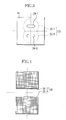
- Fig. 3 is a diagram showing the aperture stop 24 in Fig. 2 from the direction in which light is incident.
- the two oblong aperture portions 24-1 and 24-2 are arranged next to one another in the direction in which their aperture width is smaller.
- the dotted line in Fig. 3 indicates the lenses 25-1 and 25-2 of the secondary image-forming system 25, which are arranged on the exit side of the aperture portions 24-1 and 24-2 of the aperture stop 24 and in correspondence with the aperture portions 24-1 and 24-2.
- Fig. 4 shows the photoelectric conversion element 26 of Fig. 2, seen from the direction in which light is incident.
- the two area sensors 26-1 and 26-2 are sensors on which pixels are arranged two-dimensionally, as shown in Fig. 4, and the area sensors 26-1 and 26-2 are arranged next to one another.
- the two light fluxes that have passed through the two aperture portions 24-1 and 24-2 of the aperture stop 24 are converged by the lenses 25-1 and 25-2 of the secondary image-forming system 25, and their direction is changed downward by the reflection mirror 36 before they reach the area sensors 26-1 and 26-2 on the photoelectric conversion element 26.
- the light fluxes 27-1 and 27-2 in Fig. 2 are light fluxes that are images formed onto the center of the image pickup plane 11a, but also light fluxes that are images formed onto other positions reach the photoelectric conversion element 26 after passing through the same optical path. Therefore, light amount distributions (images) that are related to the object image, corresponding to the predetermined two-dimensional regions on the image pickup device 11 are formed on the area sensors 26-1 and 26-2 of the photoelectric conversion element 26.
- the focus detection unit 12 calculates, at each position on the area sensors 26-1 and 26-2, the separation direction and the separation amount of the two images, or in other words the relative positional relationship of the two images in vertical direction on the two area sensors 26-1 and 26-2 shown in Fig. 4.
- the focus detection unit 12 detects the focusing state (this is referred to as "focus detection” in the following) of the image-taking optical system 2, and outputs the result of the focus detection as the focus displacement amount (defocus amount) D.
- a correction factor that depends on the design of the lens model has been stored in advance in the memory 6 on the lens side, such that the driving position of the focusing lens 2a, for attaining an in-focus state, that is determined in accordance with this focus displacement amount D can be set to a value attaining the most precise in-focus state that is possible for the respective model of the image-taking lens 1.
- the camera 8 uses this correction factor to perform a correction such that the image pickup plane 11a matches with the best image-forming position at the time of image-taking.
- the correction factor stored in the memory 6 on the lens side does not include individual differences among image-taking lenses or individual differences of the focus detection unit 12, even when they are of the same model type, so that when the design-dependent correction factor stored in the memory 6 is used directly, then it is difficult to attain a truly accurate in-focus state.
- the differential amount between the in-focus position judged (detected) by the in-focus judgment unit 16 and the in-focus position calculated based on the output from the focus detection unit 12 is calculated by the calculation circuit 14, and this differential amount is stored in the memory 15 on the side of the camera 8 as correction information that is unique to the image-taking lens 1 that is currently mounted. It should be noted that here, this series of operations for obtaining the correction information unique to the image-taking lens 1 is also referred to as "calibration.”
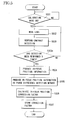
- Step 501 the calibration operation is started automatically or when the user turns on the shutter switch (Step 501 [in the drawings, steps are marked by the letter “S"]).
- the camera control circuit 13 sends a signal to the lens control circuit 5, and the focus driving unit 3 drives the focusing lens 2a into a predetermined position (Step 502).
- the contrast of the image signal obtained from the image pickup device 11 is detected by the in-focus judgment unit 16 (Step 503).
- a small moving (wobbling) of the focusing lens 2a in Step 502 and the contrast detection in Step 503 are repeated until a predetermined number N has been reached in Step 503 (Step 503a).
- the in-focus judgment unit 16 judges, based on the N contrast detection results, the position of the focusing lens 2a at which the image signal with the highest contrast is attained, takes this position as the in-focus position, and sends a signal to the camera control circuit 13.
- the camera control circuit 13 obtains the position information from the focus position detector 4 at that time through the lens control circuit 5, and produces in-focus position information (Step 504).
- the camera control circuit 13 lets the focus detection unit 12 carry out a focus detection by phase-difference detection method, and produces in-focus position information (Step 505) by adding to the position information from the focus position detector 4 a value obtained by converting the detection result for this case, or in other words the focus displacement amount (defocus amount D), into the amount that the focusing lens 2a needs to be moved in the in-focus direction.
- the camera control circuit 13 lets the calculation circuit 14 calculate the in-focus position correction factor, which is the difference between the in-focus position information at the time when the system has been judged to be in focus by the in-focus judgment unit 16 and the in-focus position information obtained as the detection result with the focus detection unit 12 (Step 506).
- the in-focus position correction factor calculated by the calculation circuit 14 is stored in the memory 15 (Step 507). This concludes the calibration.
- Step 504 and Step 505 are carried out substantially simultaneously.
- a device similar to a focus detector employing contrast detection method used in conventional video cameras was used for the in-focus judgment unit 16, but if the camera 8 is provided with a mechanical shutter, or if an image pickup device is used that cannot perform as an electronic shutter, and focus detection by conventional contrast detection cannot be carried out, then it is also possible to take a plurality of images and detect the contrast from these images.
- the in-focus position correction factor may be stored alone in the memory 15 provided in the camera 8, or it may be stored as a numerical value including the value of the correction factor C in Equation (1).
- the in-focus position correction factor also may be stored by rewriting the correction factor C in the memory 6 provided in the image-taking lens 1, or it may be stored as a correction factor separate from the correction factor C.
- the above-described calibration operation is performed for different object distances, and in-focus position correction factors associated with each object distance are stored in the memory 15. Thus, a focusing control with high precision can be performed regardless of the object distance.
- the focus detection with the focus detection unit 12 is performed after producing in-focus position information by using the in-focus judgment unit 16.
- the range over which the focusing lens is moved in Step 502 can be limited to the vicinity of the in-focus position detected by focus detection by phase difference detection method, so that the calibration can be concluded even faster.
- the in-focus position correction factor is stored separately from the correction factor C in the memory 15 in the camera 8.
- Step 601 When the shutter button of the camera 8 is subjected to a first stroke and pushed half down (Step 601) then the camera control circuit 13 lets the focus detection unit 12 carry out a focus detection by phase difference detection method (Step 602).
- the camera control circuit 13 produces in-focus position information (focusing control information), serving as the in-focus target position of the focusing lens 2a, from the moving amount of the focusing lens 2a calculated based on the focus detection result (focus displacement amount) according to the focus detection unit 12 and the current position information of the focusing lens 2a detected by the focus position detector 4. Further, the camera control circuit 13 corrects the in-focus position information by using the design-dependent correction factor C that is unique to the image-taking lens 1 and the in-focus position correction factor produced in the calibration mode (Step 603).
- the camera control circuit 13 transmits a driving command based on the corrected in-focus position information to the lens control circuit 5.
- the lens control circuit 5 moves the focusing lens 2a via the focus driving unit 3 until the position corresponding to the corrected in-focus position information is detected by the focus position detector 4, thus concluding the focusing operation (Step 604).
- Step 605 when the shutter button is subjected to a second stroke and pushed completely down (Step 605), an image is taken (Step 606).
- the difference (correction information) between the in-focus positions that are obtained in the calibration mode with the focus detection unit 12 carrying out a focus detection by phase difference detection method and with the in-focus judgment unit 16 carrying out an in-focus judgment by contrast detection method is stored, and the focusing control information obtained by the focus detection unit 12 is corrected with this stored correction information when taking an image
- a focusing control of high-precision becomes possible while maintaining the high speed due to phase difference detection method.
- the in-focus position correction factor in the memory 15 inside the camera 8 as a numerical value including the correction factor C as described above, it is not necessary anymore to transmit the correction factor C between the image-taking lens 1 and the camera 8, so that an even faster focusing control becomes possible.
- Fig. 7 is a flowchart of the calibration operation in a single lens reflex digital camera system according to Embodiment 2 of the present invention. It should be noted that the structure of this camera system is similar to that of Embodiment 1. Therefore, structural elements that are shared with Embodiment 1 are assigned the same numerals as in Embodiment 1. In this embodiment, the in-focus position correction factor is calculated automatically without setting a calibration mode.
- Step 701 When the calibration starts (Step 701), first, the camera control circuit 13 lets the focus detection unit 12 perform focus detection employing phase difference detection method, and in-focus position information is produced in a similar manner as in Embodiment 1 (Step 702). Then, based on this in-focus position information, the focusing lens 2a is driven through the lens control circuit 5 and the focus driving unit 3, and a focusing operation is carried out (Step 703).
- Step 704 the camera control circuit 13 moves the focusing lens 2a, which is in the position into which it has been moved by the focus driving unit 3, by a tiny amount in Step 703 (Step 704).
- the camera control circuit 13 lets the in-focus judgment unit 16 carry out a contrast detection (Step 705), and after Step 704 and Step 705 have been repeated a predetermined N times (Step 705a), in-focus position information is produced from the position (detected by the focus position detector 4) of the focusing lens 2a at which the image signal has the highest contrast of all detected contrasts (Step 706).
- the in-focus position correction factor which is the difference between the in-focus position information obtained at Step 706 and the in-focus position information obtained by using the focus detection unit 12 at Step 702, is calculated with the calculation circuit 14 (Step 707).
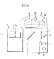
- Fig. 8 illustrates the structure of a single lens reflex digital camera according to Embodiment 3 of the present invention. It should be noted that structural elements that are shared with Embodiment 1 are given the same numerals as in Embodiment 1. However, structural elements relating to the in-focus position calibration explained in Embodiments 1 and 2 have been omitted from Fig. 8.
- a photometry unit 20 an exposure control circuit 21 controlling the exposure of the image pickup device 11, an exposure amount detection circuit 22 for detecting an exposure amount of the image pickup device 11, a camera control circuit 13' that also serves as a calculation circuit, and a memory 24 have been added to the structure of the camera 8 of Embodiment 1.
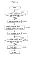
- the camera control circuit 13' lets the photometry unit 20 carry out a photometry operation (Step 902). After that, the exposure value is set based on the result of the value of photometry with the photometry unit 12 (Step 903), and an image of the object is taken with the set exposure value (Step 904).
- Step 903 the exposure value set in Step 903 is altered by a predetermined value (Step 905), and an image is taken with this altered exposure value (Step 906).
- Step 905 and Step 906 have been repeated for a predetermined N times (Step 906a)
- the exposure amounts of the N images taken at Step 904 and Step 906, are detected with the exposure amount detection circuit 22, and the exposure value for the best exposure amount of those detected N exposure amounts is calculated and taken as the optimum exposure value (Step 907).
- Step 903 the difference between this optimum exposure value and the exposure value that has been set at Step 903 is calculated by the camera control circuit 13', which also serves as a calculation circuit (Step 908).
- the camera control circuit 13' stores the calculated difference as the exposure correction factor in the memory 24 (Step 909). This concludes the calibration of the exposure.
- Step 1001 When the user subjects the shutter button to a first stroke and pushes it half down (Step 1001) then the camera control circuit 13' lets the photometry unit 20 perform photometry operation (Step 1002). Then, the exposure value obtained based on the photometry result with the photometry unit 20 is corrected with the exposure correction factor stored in the memory 24 (Step 1003). Moreover, the exposure value setting during image-taking is performed based on this corrected result (Step 1004).
- Step 1005 When the shutter button is subjected to a second stroke and pushed completely down (Step 1005), the camera control circuit 13' performs an image-taking operation (Step 1006).
- an exposure correction during image-taking is performed by using the exposure correction factor obtained by the exposure calibration, so that an optimum exposure value setting can be attained.
- the in-focus position calibration explained in Embodiment 1 and 2 and the exposure calibration explained in this embodiment are performed every time the image-taking lens 1 is exchanged, and therefore it is preferable that if the in-focus position correction factor and the exposure correction factor corresponding to the newly mounted image-taking lens 1 are not stored in the memory of the camera 8, the user is alerted to this fact by a warning tone or display.
- the in-focus position correction factor and the exposure correction factor are stored in the storage circuit provided in the camera 8, but it is also possible to overwrite the prior correction value that was stored in the memory provided inside the image-taking lens 1.
- correction information for compensating the inadequacy of the detection precision of phase difference detection method which is superior with regard to its high speed, is determined based on information indicating the in-focus state obtained by using contrast detection of the image, which allows an in-focus judgment of high precision.
- a focusing control can be performed with high precision and at a speed that is faster than in phase difference detection method and hybrid method.
- the correction information is stored in a memory in association with individual information of each individual image-taking lens, and the focusing control information is corrected by using the correction information stored in the memory that corresponds to the individual information obtained from the mounted image-taking lens, it becomes possible to correct the detection result detected with the focus detection unit (embodying phase difference detection method) by using correction information matching the optical characteristics unique to each image-taking lens, and it becomes possible to ensure the highest level of precision regardless of the mounted image-taking lens.
Landscapes
- Engineering & Computer Science (AREA)
- Multimedia (AREA)
- Signal Processing (AREA)
- Physics & Mathematics (AREA)
- General Physics & Mathematics (AREA)
- Optics & Photonics (AREA)
- Automatic Focus Adjustment (AREA)
- Studio Devices (AREA)
- Focusing (AREA)
- Exposure Control For Cameras (AREA)
Abstract
Description
Claims (13)
- An image pickup apparatus on which an image-taking lens can be mounted and removed, characterized in that it comprises:an image pickup device that receives an object image formed by the image-taking lens and photoelectrically converts the object image;a focus detection unit that detects a focusing state of the image-taking lens by phase difference detection method using light from the image-taking lens;an in-focus judgment unit, which judges whether the image-taking lens is in an in-focus state or not, based on a result of a detection of contrast of an the object image that has been photoelectrically converted by the image pickup device; anda processing unit, which determines correction information for correcting focusing control information of the image-taking lens that has been obtained by using the focus detection unit, based on information indicating the in-focus state of the image-taking lens obtained by using the in-focus judgment unit.
- The image pickup apparatus according to claim 1, characterized in that the processing unit determines the correction information based on a difference between in-focus position information of the image-taking lens obtained by using the focus detection unit and in-focus position information obtained by using the in-focus judgment unit.
- The image pickup apparatus according to claim 2, characterized in that the in-focus judgment unit carries out a plurality of in-focus/out-of-focus judgments while moving a focusing lens unit that is included in the image-taking lens.
- The image pickup apparatus according to claim 1, characterized in that it further comprises a memory, which stores the correction information;
wherein the processing unit reads out the correction information from the memory. - The image pickup apparatus according to claim 4, characterized in that
the memory stores the correction information in correspondence with individual information for a plurality of image-taking lenses; and
the processing unit reads, from the correction information stored in the memory, the correction information that corresponds to the individual information obtained from the image-taking lens mounted to the image pickup apparatus. - The image pickup apparatus according to claim 5, characterized in that the processing unit obtains design-dependent correction information, stored in the memory which is in the image-taking lens, for correcting a detection result detected by the focus detection unit, and corrects the design-dependent information by using the correction information stored in the memory in correspondence with the individual information.
- The image pickup apparatus according to claim 1, characterized in that it is possible to set a calibration mode in which an operation for determining the correction information is carried out.
- The image pickup apparatus according to claim 1, characterized in that the processing unit outputs a signal for focusing control of the image-taking lens in correspondence with the focusing control information corrected by using the correction information.
- The image pickup apparatus according to claim 1, characterized in that the in-focus judgment unit carries out an in-focus/out-of-focus judgment by contrast detection method.
- An image pickup system, characterized in that it comprises:the image pickup apparatus according to claim 1; andan image-taking lens allowing focus control that can be mounted on and removed from the image pickup apparatus.
- An image pickup system, characterized in that it comprises:the image pickup apparatus according to claim 5; andan image-taking lens allowing focus control that can be mounted on and removed from the image pickup apparatus, that stores the individual information, and that can transmit the individual information to the image-taking apparatus.
- An image pickup apparatus on which an image-taking lens can be mounted and removed, characterized in that it comprises:an image pickup device that receives an object image formed by the image-taking lens and photoelectrically converts the object image;a photometry unit that performs photometry by using light from the image-taking lens,a detecting device electrically connected to the image pickup device, which detects an exposure amount being received by the image pickup device,a processing unit electrically connected to the photometry unit and the detecting unit, which determines correction information for correcting exposure information obtained by using the photometry unit, based on information obtained by using the detecting unit.
- An image pickup system characterized in that it comprises:the image pickup apparatus according to claim 12; andan image-taking lens that can be mounted on and removed from the image pickup apparatus.
Priority Applications (1)
| Application Number | Priority Date | Filing Date | Title |
|---|---|---|---|
| EP04078141A EP1507157B1 (en) | 2002-04-05 | 2003-03-31 | Image pickup apparatus with a focus adjusting device and an exposure system |
Applications Claiming Priority (2)
| Application Number | Priority Date | Filing Date | Title |
|---|---|---|---|
| JP2002104403 | 2002-04-05 | ||
| JP2002104403A JP2003295047A (en) | 2002-04-05 | 2002-04-05 | Imaging device and imaging system |
Related Child Applications (1)
| Application Number | Title | Priority Date | Filing Date |
|---|---|---|---|
| EP04078141A Division EP1507157B1 (en) | 2002-04-05 | 2003-03-31 | Image pickup apparatus with a focus adjusting device and an exposure system |
Publications (3)
| Publication Number | Publication Date |
|---|---|
| EP1351086A2 true EP1351086A2 (en) | 2003-10-08 |
| EP1351086A3 EP1351086A3 (en) | 2003-11-12 |
| EP1351086B1 EP1351086B1 (en) | 2005-07-13 |
Family
ID=28035966
Family Applications (2)
| Application Number | Title | Priority Date | Filing Date |
|---|---|---|---|
| EP04078141A Expired - Lifetime EP1507157B1 (en) | 2002-04-05 | 2003-03-31 | Image pickup apparatus with a focus adjusting device and an exposure system |
| EP03252048A Expired - Lifetime EP1351086B1 (en) | 2002-04-05 | 2003-03-31 | Image pickup apparatus with a focus adjusting device and an exposure system |
Family Applications Before (1)
| Application Number | Title | Priority Date | Filing Date |
|---|---|---|---|
| EP04078141A Expired - Lifetime EP1507157B1 (en) | 2002-04-05 | 2003-03-31 | Image pickup apparatus with a focus adjusting device and an exposure system |
Country Status (5)
| Country | Link |
|---|---|
| US (1) | US6941068B2 (en) |
| EP (2) | EP1507157B1 (en) |
| JP (1) | JP2003295047A (en) |
| CN (1) | CN1450398A (en) |
| DE (2) | DE60300994T2 (en) |
Cited By (10)
| Publication number | Priority date | Publication date | Assignee | Title |
|---|---|---|---|---|
| EP1545122A1 (en) * | 2003-12-15 | 2005-06-22 | Canon Kabushiki Kaisha | Camera, camera system and lens apparatus |
| WO2010007772A1 (en) | 2008-07-15 | 2010-01-21 | Canon Kabushiki Kaisha | Focal point adjusting apparatus, image-taking apparatus, interchangeable lens, conversion coefficient calibrating method, and conversion coefficient calibrating program |
| US8311407B2 (en) | 2008-03-28 | 2012-11-13 | Panasonic Corporation | Camera system, camera body, and interchangeable lens |
| US8363154B2 (en) | 2008-05-30 | 2013-01-29 | Samsung Electronics Co., Ltd. | Focus error adjusting apparatus and method in digital image processing device |
| EP2515525A3 (en) * | 2011-04-21 | 2013-05-22 | Canon Kabushiki Kaisha | Image pickup apparatus and control method thereof |
| US8521016B2 (en) | 2008-03-28 | 2013-08-27 | Panasonic Corporation | Camera system |
| US8588599B2 (en) | 2009-10-15 | 2013-11-19 | Canon Kabushiki Kaisha | Imaging apparatus and focus control method for the imaging apparatus |
| EP2894845A1 (en) * | 2003-12-15 | 2015-07-15 | Canon Kabushiki Kaisha | Camera, camera system and lens apparatus |
| EP2996325A3 (en) * | 2014-09-15 | 2016-05-11 | LG Electronics Inc. | Mobile terminal and method of controlling the same |
| US11611693B1 (en) * | 2021-11-30 | 2023-03-21 | Motorola Mobility Llc | Updating lens focus calibration values |
Families Citing this family (69)
| Publication number | Priority date | Publication date | Assignee | Title |
|---|---|---|---|---|
| JP4125101B2 (en) * | 2002-12-06 | 2008-07-30 | キヤノン株式会社 | IMAGING DEVICE, AUTOMATIC FOCUSING DEVICE, AND CONTROL METHOD THEREOF |
| US7002598B2 (en) * | 2003-03-25 | 2006-02-21 | Mitsubishi Electric Research Labs., Inc. | Method for generating a composite glyph and rendering a region of the composite glyph in object-order |
| US7123271B2 (en) * | 2003-03-25 | 2006-10-17 | Mitsubishi Electric Research Labs, Inc. | Method and apparatus for antialiasing a set of objects represented as a set of two-dimensional distance fields in image-order |
| US7006108B2 (en) * | 2003-03-25 | 2006-02-28 | Mitsubishi Electric Research Laboratories, Inc. | Method for generating a composite glyph and rendering a region of the composite glyph in image-order |
| US7207422B2 (en) * | 2003-04-01 | 2007-04-24 | Mitsubishi Denki Kabushiki Kaisha | Elevator call recording device |
| JP4532865B2 (en) * | 2003-09-09 | 2010-08-25 | キヤノン株式会社 | Imaging device and focus control method of imaging device |
| US7590305B2 (en) | 2003-09-30 | 2009-09-15 | Fotonation Vision Limited | Digital camera with built-in lens calibration table |
| US7369712B2 (en) | 2003-09-30 | 2008-05-06 | Fotonation Vision Limited | Automated statistical self-calibrating detection and removal of blemishes in digital images based on multiple occurrences of dust in images |
| US7340109B2 (en) | 2003-09-30 | 2008-03-04 | Fotonation Vision Limited | Automated statistical self-calibrating detection and removal of blemishes in digital images dependent upon changes in extracted parameter values |
| US7310450B2 (en) | 2003-09-30 | 2007-12-18 | Fotonation Vision Limited | Method of detecting and correcting dust in digital images based on aura and shadow region analysis |
| US7424170B2 (en) | 2003-09-30 | 2008-09-09 | Fotonation Vision Limited | Automated statistical self-calibrating detection and removal of blemishes in digital images based on determining probabilities based on image analysis of single images |
| US7308156B2 (en) | 2003-09-30 | 2007-12-11 | Fotonation Vision Limited | Automated statistical self-calibrating detection and removal of blemishes in digital images based on a dust map developed from actual image data |
| US7295233B2 (en) | 2003-09-30 | 2007-11-13 | Fotonation Vision Limited | Detection and removal of blemishes in digital images utilizing original images of defocused scenes |
| US8369650B2 (en) | 2003-09-30 | 2013-02-05 | DigitalOptics Corporation Europe Limited | Image defect map creation using batches of digital images |
| JP4663246B2 (en) * | 2004-02-16 | 2011-04-06 | キヤノン株式会社 | Camera, camera system and lens apparatus |
| JP2006003533A (en) * | 2004-06-16 | 2006-01-05 | Canon Inc | Imaging apparatus, focus control method, and program |
| US20050174085A1 (en) * | 2004-02-10 | 2005-08-11 | Olympus Corporation | Micromanipulation system |
| JP4042710B2 (en) * | 2004-02-25 | 2008-02-06 | カシオ計算機株式会社 | Autofocus device and program thereof |
| JP4933035B2 (en) * | 2004-06-28 | 2012-05-16 | キヤノン株式会社 | IMAGING DEVICE AND IMAGING DEVICE CONTROL METHOD |
| JP4551708B2 (en) * | 2004-07-21 | 2010-09-29 | キヤノン株式会社 | Imaging device |
| JP4630649B2 (en) * | 2004-11-24 | 2011-02-09 | キヤノン株式会社 | camera |
| JP4560420B2 (en) * | 2005-02-04 | 2010-10-13 | キヤノン株式会社 | Imaging device |
| JP5121120B2 (en) * | 2005-02-08 | 2013-01-16 | キヤノン株式会社 | Focus detection apparatus and optical instrument |
| JP4764090B2 (en) * | 2005-08-01 | 2011-08-31 | キヤノン株式会社 | Focus detection apparatus and photographing apparatus |
| JP4865275B2 (en) * | 2005-08-29 | 2012-02-01 | キヤノン株式会社 | Focus detection apparatus and imaging apparatus |
| JP2007086596A (en) * | 2005-09-26 | 2007-04-05 | Pentax Corp | camera |
| JP4736695B2 (en) * | 2005-10-12 | 2011-07-27 | 株式会社ニコン | camera |
| JP2007156304A (en) * | 2005-12-08 | 2007-06-21 | Canon Inc | Camera, camera system and interchangeable lens device |
| WO2007095556A2 (en) | 2006-02-14 | 2007-08-23 | Fotonation Vision Limited | Digital image acquisition device with built in dust and sensor mapping capability |
| US20070188651A1 (en) * | 2006-02-14 | 2007-08-16 | Akihiro Machida | Automatically capturing focused images obtained through unguided manual focus adjustment |
| CN100533199C (en) * | 2006-05-02 | 2009-08-26 | 佳能株式会社 | Focus detection apparatus, optical apparatus and imaging system |
| JP2008015274A (en) * | 2006-07-06 | 2008-01-24 | Olympus Imaging Corp | Digital camera |
| JP4795155B2 (en) * | 2006-07-28 | 2011-10-19 | キヤノン株式会社 | Optical device, imaging device, and control method thereof |
| JP4863370B2 (en) * | 2006-08-03 | 2012-01-25 | キヤノン株式会社 | Imaging device |
| JP2008129455A (en) * | 2006-11-22 | 2008-06-05 | Sony Corp | Imaging apparatus, control method, and program |
| JP4285546B2 (en) | 2007-01-16 | 2009-06-24 | ソニー株式会社 | Imaging system, imaging apparatus, and interchangeable lens |
| US8095000B2 (en) | 2007-02-15 | 2012-01-10 | Panasonic Corporation | Camera system |
| JP5247044B2 (en) * | 2007-02-16 | 2013-07-24 | キヤノン株式会社 | Imaging device |
| JP5020710B2 (en) * | 2007-06-06 | 2012-09-05 | キヤノン株式会社 | Imaging device and interchangeable lens |
| JP5264131B2 (en) * | 2007-09-14 | 2013-08-14 | キヤノン株式会社 | Imaging device |
| JP5317562B2 (en) * | 2008-07-17 | 2013-10-16 | キヤノン株式会社 | Phase difference detection device, imaging device, phase difference detection method, phase difference detection program |
| JP5388544B2 (en) | 2008-11-05 | 2014-01-15 | キヤノン株式会社 | Imaging apparatus and focus control method thereof |
| CN101753833B (en) * | 2008-12-17 | 2012-07-04 | 比亚迪股份有限公司 | Camera module focusing detection method, device and system and detection equipment |
| JP5322783B2 (en) * | 2009-06-05 | 2013-10-23 | キヤノン株式会社 | IMAGING DEVICE AND CONTROL METHOD OF IMAGING DEVICE |
| JP2011017800A (en) * | 2009-07-07 | 2011-01-27 | Canon Inc | Focus detection apparatus |
| JP5448621B2 (en) * | 2009-07-27 | 2014-03-19 | キヤノン株式会社 | IMAGING DEVICE AND IMAGING DEVICE CONTROL METHOD |
| KR101176840B1 (en) * | 2009-12-22 | 2012-08-23 | 삼성전자주식회사 | Camera and method for auto-focusing |
| JP5932210B2 (en) * | 2010-04-30 | 2016-06-08 | キヤノン株式会社 | Imaging apparatus and focus adjustment method |
| JP2011002848A (en) * | 2010-08-20 | 2011-01-06 | Canon Inc | Imaging device |
| JP5821187B2 (en) * | 2010-12-24 | 2015-11-24 | ソニー株式会社 | Imaging system, mount adapter, imaging apparatus, and program |
| JP5808123B2 (en) * | 2011-03-24 | 2015-11-10 | キヤノン株式会社 | IMAGING DEVICE, IMAGING DEVICE CONTROL METHOD, AND PROGRAM |
| JP5906235B2 (en) * | 2011-03-25 | 2016-04-20 | キヤノン株式会社 | Imaging device |
| JP5930621B2 (en) * | 2011-07-15 | 2016-06-08 | キヤノン株式会社 | Imaging apparatus, control method therefor, and computer program |
| DE102012003127A1 (en) * | 2012-02-16 | 2013-09-05 | Leica Camera Ag | Method for an autofocus device |
| CN102692815B (en) * | 2012-05-23 | 2014-05-21 | 深圳市华星光电技术有限公司 | Photomask and method for manufacturing same |
| JP6239857B2 (en) * | 2013-05-13 | 2017-11-29 | キヤノン株式会社 | Imaging apparatus and control method thereof |
| JP6194642B2 (en) * | 2013-05-31 | 2017-09-13 | 株式会社ニコン | interchangeable lens |
| JP6335482B2 (en) | 2013-11-13 | 2018-05-30 | キヤノン株式会社 | Imaging apparatus, control method therefor, and program |
| JP6320100B2 (en) * | 2014-03-19 | 2018-05-09 | キヤノン株式会社 | Imaging apparatus, control method thereof, and program |
| JP6457740B2 (en) * | 2014-05-13 | 2019-01-23 | キヤノン株式会社 | IMAGING DEVICE AND ITS CONTROL METHOD, LENS UNIT, IMAGING SYSTEM |
| JP6298362B2 (en) * | 2014-06-02 | 2018-03-20 | キヤノン株式会社 | Imaging apparatus, control method therefor, and imaging system |
| CN106534666A (en) * | 2016-10-11 | 2017-03-22 | 广东欧珀移动通信有限公司 | Phase focusing method, device and terminal equipment |
| CN106371266A (en) * | 2016-10-18 | 2017-02-01 | 安徽协创物联网技术有限公司 | Double-stroke type automatic focusing system of panorama camera |
| CN108243305B (en) * | 2016-12-26 | 2020-12-15 | 聚晶半导体股份有限公司 | Image capture device and its phase focus correction method |
| JP6946045B2 (en) * | 2017-04-28 | 2021-10-06 | キヤノン株式会社 | Focus detector and imaging system |
| JP6508267B2 (en) * | 2017-08-17 | 2019-05-08 | 株式会社ニコン | interchangeable lens |
| CN109981965B (en) * | 2017-12-27 | 2021-01-01 | 华为技术有限公司 | Focusing method and electronic equipment |
| CN108184055A (en) * | 2017-12-28 | 2018-06-19 | 上海传英信息技术有限公司 | A kind of focusing method and focusing mechanism based on intelligent terminal |
| JP7718837B2 (en) * | 2021-03-30 | 2025-08-05 | キヤノン株式会社 | Distance measurement device, moving device, distance measurement method, moving device control method, and computer program |
Family Cites Families (18)
| Publication number | Priority date | Publication date | Assignee | Title |
|---|---|---|---|---|
| JPH0629895B2 (en) * | 1984-09-11 | 1994-04-20 | キヤノン株式会社 | Focus state determination device |
| US5231448A (en) * | 1989-08-07 | 1993-07-27 | Nikon Corporation | Photometric apparatus for a camera |
| JPH0456936A (en) | 1990-06-26 | 1992-02-24 | Minolta Camera Co Ltd | Focal point detector for camera |
| FR2676552B1 (en) * | 1991-05-15 | 1996-01-12 | Asahi Optical Co Ltd | AUTOMATIC FOCUSING DEVICE. |
| JPH0635027A (en) * | 1992-07-22 | 1994-02-10 | Nikon Corp | Camera automatic exposure device and camera photometric device |
| JPH0743605A (en) * | 1993-08-02 | 1995-02-14 | Minolta Co Ltd | Automatic focusing device |
| US5664238A (en) * | 1994-11-28 | 1997-09-02 | Ricoh Company, Ltd. | Focal controller of camera |
| US6115553A (en) * | 1996-09-17 | 2000-09-05 | Asahi Kogaku Kogyo Kabushiki Kaisha | Multipoint autofocus system |
| JPH10301020A (en) | 1997-04-30 | 1998-11-13 | Canon Inc | Focus detection device |
| US6088537A (en) | 1997-04-15 | 2000-07-11 | Canon Kabushiki Kaisha | Focus detecting device |
| JPH1138462A (en) * | 1997-07-14 | 1999-02-12 | Nikon Corp | Camera photometer |
| US6035135A (en) * | 1997-08-21 | 2000-03-07 | Canon Kabushiki Kaisha | Control of flash device included in or connected to image sensing device |
| JPH1164919A (en) * | 1997-08-21 | 1999-03-05 | Canon Inc | Image pickup device |
| JP2000032148A (en) | 1998-07-10 | 2000-01-28 | Hitachi Ltd | Arrears managing and dunning method |
| JP4331314B2 (en) | 1999-04-12 | 2009-09-16 | オリンパス株式会社 | Single-lens reflex type electronic imaging device |
| JP2000321482A (en) * | 1999-05-11 | 2000-11-24 | Kyocera Corp | Automatic focus adjustment device |
| US6453124B2 (en) * | 2000-03-27 | 2002-09-17 | Minolta Co., Ltd. | Digital camera |
| US6813442B2 (en) * | 2000-06-08 | 2004-11-02 | Canon Kabushiki Kaisha | Autofocus system and camera system |
-
2002
- 2002-04-05 JP JP2002104403A patent/JP2003295047A/en active Pending
-
2003
- 2003-03-31 EP EP04078141A patent/EP1507157B1/en not_active Expired - Lifetime
- 2003-03-31 EP EP03252048A patent/EP1351086B1/en not_active Expired - Lifetime
- 2003-03-31 DE DE60300994T patent/DE60300994T2/en not_active Expired - Lifetime
- 2003-03-31 DE DE60307092T patent/DE60307092D1/en not_active Expired - Lifetime
- 2003-04-01 US US10/404,528 patent/US6941068B2/en not_active Expired - Lifetime
- 2003-04-04 CN CN03109347A patent/CN1450398A/en active Pending
Cited By (18)
| Publication number | Priority date | Publication date | Assignee | Title |
|---|---|---|---|---|
| EP1545122A1 (en) * | 2003-12-15 | 2005-06-22 | Canon Kabushiki Kaisha | Camera, camera system and lens apparatus |
| EP2894845A1 (en) * | 2003-12-15 | 2015-07-15 | Canon Kabushiki Kaisha | Camera, camera system and lens apparatus |
| US7872684B2 (en) | 2003-12-15 | 2011-01-18 | Canon Kabushiki Kaisha | Camera capable of correcting information for focusing control, using information stored in storage section of mounted lens apparatus |
| US8723985B2 (en) | 2003-12-15 | 2014-05-13 | Canon Kabushiki Kaisha | Camera, camera system and lens apparatus |
| US8531585B2 (en) | 2003-12-15 | 2013-09-10 | Canon Kabushiki Kaisha | Camera, camera system and lens apparatus |
| US8395690B2 (en) | 2003-12-15 | 2013-03-12 | Canon Kabushiki Kaisha | Camera, camera system and lens apparatus |
| US8521016B2 (en) | 2008-03-28 | 2013-08-27 | Panasonic Corporation | Camera system |
| US8542314B2 (en) | 2008-03-28 | 2013-09-24 | Panasonic Corporation | Camera system including camera body and interchangeable lens for performing focus control |
| US8311407B2 (en) | 2008-03-28 | 2012-11-13 | Panasonic Corporation | Camera system, camera body, and interchangeable lens |
| GB2460312B (en) * | 2008-05-30 | 2013-03-13 | Samsung Electronics Co Ltd | Focus error adjusting apparatus and method in digital image processing device |
| US8363154B2 (en) | 2008-05-30 | 2013-01-29 | Samsung Electronics Co., Ltd. | Focus error adjusting apparatus and method in digital image processing device |
| EP2307920A4 (en) * | 2008-07-15 | 2014-06-25 | Canon Kk | Focal point adjusting apparatus, image-taking apparatus, interchangeable lens, conversion coefficient calibrating method, and conversion coefficient calibrating program |
| WO2010007772A1 (en) | 2008-07-15 | 2010-01-21 | Canon Kabushiki Kaisha | Focal point adjusting apparatus, image-taking apparatus, interchangeable lens, conversion coefficient calibrating method, and conversion coefficient calibrating program |
| US8588599B2 (en) | 2009-10-15 | 2013-11-19 | Canon Kabushiki Kaisha | Imaging apparatus and focus control method for the imaging apparatus |
| EP2515525A3 (en) * | 2011-04-21 | 2013-05-22 | Canon Kabushiki Kaisha | Image pickup apparatus and control method thereof |
| EP2996325A3 (en) * | 2014-09-15 | 2016-05-11 | LG Electronics Inc. | Mobile terminal and method of controlling the same |
| US9681038B2 (en) | 2014-09-15 | 2017-06-13 | Lg Electronics Inc. | Mobile terminal and method for setting a focal point value |
| US11611693B1 (en) * | 2021-11-30 | 2023-03-21 | Motorola Mobility Llc | Updating lens focus calibration values |
Also Published As
| Publication number | Publication date |
|---|---|
| US20030189662A1 (en) | 2003-10-09 |
| EP1351086A3 (en) | 2003-11-12 |
| DE60300994T2 (en) | 2006-04-27 |
| EP1351086B1 (en) | 2005-07-13 |
| EP1507157B1 (en) | 2006-07-26 |
| DE60307092D1 (en) | 2006-09-07 |
| EP1507157A2 (en) | 2005-02-16 |
| JP2003295047A (en) | 2003-10-15 |
| US6941068B2 (en) | 2005-09-06 |
| DE60300994D1 (en) | 2005-08-18 |
| CN1450398A (en) | 2003-10-22 |
| EP1507157A3 (en) | 2005-03-02 |
Similar Documents
| Publication | Publication Date | Title |
|---|---|---|
| EP1351086B1 (en) | Image pickup apparatus with a focus adjusting device and an exposure system | |
| US6097897A (en) | Camera | |
| US20040183939A1 (en) | Camera having AF function | |
| JP5168798B2 (en) | Focus adjustment device and imaging device | |
| US7940323B2 (en) | Image-pickup apparatus and control method thereof | |
| JP2005107213A (en) | Automatic focusing device for camera | |
| JP2008275712A (en) | Imaging device | |
| JP4972960B2 (en) | Focus adjustment device and imaging device | |
| JP5168797B2 (en) | Imaging device | |
| JP2006065080A (en) | Imaging device | |
| JP5241096B2 (en) | IMAGING DEVICE, ITS CONTROL METHOD, PROGRAM, AND STORAGE MEDIUM | |
| JP2004109864A (en) | Imaging device and imaging system having the same | |
| JP2005308960A (en) | Imaging device with automatic focusing device | |
| JP2006084545A (en) | Camera, photographing lens and camera system | |
| JP4560420B2 (en) | Imaging device | |
| JP5157073B2 (en) | Focus adjustment device and imaging device | |
| JP6355348B2 (en) | IMAGING DEVICE, IMAGING SYSTEM, IMAGING DEVICE CONTROL METHOD, PROGRAM, AND STORAGE MEDIUM | |
| JP2007156304A (en) | Camera, camera system and interchangeable lens device | |
| JP4865275B2 (en) | Focus detection apparatus and imaging apparatus | |
| JP4541808B2 (en) | Imaging apparatus and imaging system | |
| JP2004069953A (en) | camera | |
| JP2006184321A (en) | FOCUS DETECTION DEVICE AND OPTICAL DEVICE HAVING FOCUS DETECTION DEVICE | |
| JP2001141986A (en) | Electronic camera and automatic focusing device for electronic camera | |
| JPH0643356A (en) | Focus detector | |
| JP4928236B2 (en) | Imaging apparatus and imaging system |
Legal Events
| Date | Code | Title | Description |
|---|---|---|---|
| PUAI | Public reference made under article 153(3) epc to a published international application that has entered the european phase |
Free format text: ORIGINAL CODE: 0009012 |
|
| PUAL | Search report despatched |
Free format text: ORIGINAL CODE: 0009013 |
|
| AK | Designated contracting states |
Kind code of ref document: A2 Designated state(s): AT BE BG CH CY CZ DE DK EE ES FI FR GB GR HU IE IT LI LU MC NL PT RO SE SI SK TR |
|
| AX | Request for extension of the european patent |
Extension state: AL LT LV MK |
|
| AK | Designated contracting states |
Kind code of ref document: A3 Designated state(s): AT BE BG CH CY CZ DE DK EE ES FI FR GB GR HU IE IT LI LU MC NL PT RO SE SI SK TR |
|
| AX | Request for extension of the european patent |
Extension state: AL LT LV MK |
|
| 17P | Request for examination filed |
Effective date: 20040326 |
|
| 17Q | First examination report despatched |
Effective date: 20040427 |
|
| AKX | Designation fees paid |
Designated state(s): DE FR GB IT NL SE |
|
| GRAP | Despatch of communication of intention to grant a patent |
Free format text: ORIGINAL CODE: EPIDOSNIGR1 |
|
| GRAS | Grant fee paid |
Free format text: ORIGINAL CODE: EPIDOSNIGR3 |
|
| GRAA | (expected) grant |
Free format text: ORIGINAL CODE: 0009210 |
|
| AK | Designated contracting states |
Kind code of ref document: B1 Designated state(s): DE FR GB IT NL SE |
|
| PG25 | Lapsed in a contracting state [announced via postgrant information from national office to epo] |
Ref country code: IT Free format text: LAPSE BECAUSE OF FAILURE TO SUBMIT A TRANSLATION OF THE DESCRIPTION OR TO PAY THE FEE WITHIN THE PRESCRIBED TIME-LIMIT;WARNING: LAPSES OF ITALIAN PATENTS WITH EFFECTIVE DATE BEFORE 2007 MAY HAVE OCCURRED AT ANY TIME BEFORE 2007. THE CORRECT EFFECTIVE DATE MAY BE DIFFERENT FROM THE ONE RECORDED. Effective date: 20050713 Ref country code: NL Free format text: LAPSE BECAUSE OF FAILURE TO SUBMIT A TRANSLATION OF THE DESCRIPTION OR TO PAY THE FEE WITHIN THE PRESCRIBED TIME-LIMIT Effective date: 20050713 |
|
| REG | Reference to a national code |
Ref country code: GB Ref legal event code: FG4D |
|
| REF | Corresponds to: |
Ref document number: 60300994 Country of ref document: DE Date of ref document: 20050818 Kind code of ref document: P |
|
| PG25 | Lapsed in a contracting state [announced via postgrant information from national office to epo] |
Ref country code: SE Free format text: LAPSE BECAUSE OF FAILURE TO SUBMIT A TRANSLATION OF THE DESCRIPTION OR TO PAY THE FEE WITHIN THE PRESCRIBED TIME-LIMIT Effective date: 20051013 |
|
| NLV1 | Nl: lapsed or annulled due to failure to fulfill the requirements of art. 29p and 29m of the patents act | ||
| PLBE | No opposition filed within time limit |
Free format text: ORIGINAL CODE: 0009261 |
|
| STAA | Information on the status of an ep patent application or granted ep patent |
Free format text: STATUS: NO OPPOSITION FILED WITHIN TIME LIMIT |
|
| 26N | No opposition filed |
Effective date: 20060418 |
|
| EN | Fr: translation not filed | ||
| PG25 | Lapsed in a contracting state [announced via postgrant information from national office to epo] |
Ref country code: FR Free format text: LAPSE BECAUSE OF FAILURE TO SUBMIT A TRANSLATION OF THE DESCRIPTION OR TO PAY THE FEE WITHIN THE PRESCRIBED TIME-LIMIT Effective date: 20060908 |
|
| PG25 | Lapsed in a contracting state [announced via postgrant information from national office to epo] |
Ref country code: FR Free format text: LAPSE BECAUSE OF FAILURE TO SUBMIT A TRANSLATION OF THE DESCRIPTION OR TO PAY THE FEE WITHIN THE PRESCRIBED TIME-LIMIT Effective date: 20050713 |
|
| PGFP | Annual fee paid to national office [announced via postgrant information from national office to epo] |
Ref country code: GB Payment date: 20190327 Year of fee payment: 17 |
|
| PGFP | Annual fee paid to national office [announced via postgrant information from national office to epo] |
Ref country code: DE Payment date: 20190531 Year of fee payment: 17 |
|
| REG | Reference to a national code |
Ref country code: DE Ref legal event code: R119 Ref document number: 60300994 Country of ref document: DE |
|
| PG25 | Lapsed in a contracting state [announced via postgrant information from national office to epo] |
Ref country code: DE Free format text: LAPSE BECAUSE OF NON-PAYMENT OF DUE FEES Effective date: 20201001 |
|
| GBPC | Gb: european patent ceased through non-payment of renewal fee |
Effective date: 20200331 |
|
| PG25 | Lapsed in a contracting state [announced via postgrant information from national office to epo] |
Ref country code: GB Free format text: LAPSE BECAUSE OF NON-PAYMENT OF DUE FEES Effective date: 20200331 |