EP1350954A1 - Stellvorrichtung mit Formgedächtniselement - Google Patents
Stellvorrichtung mit Formgedächtniselement Download PDFInfo
- Publication number
- EP1350954A1 EP1350954A1 EP03006691A EP03006691A EP1350954A1 EP 1350954 A1 EP1350954 A1 EP 1350954A1 EP 03006691 A EP03006691 A EP 03006691A EP 03006691 A EP03006691 A EP 03006691A EP 1350954 A1 EP1350954 A1 EP 1350954A1
- Authority
- EP
- European Patent Office
- Prior art keywords
- shape memory
- memory element
- control unit
- adjusting device
- influencing variable
- Prior art date
- Legal status (The legal status is an assumption and is not a legal conclusion. Google has not performed a legal analysis and makes no representation as to the accuracy of the status listed.)
- Granted
Links
Images


Classifications
-
- F—MECHANICAL ENGINEERING; LIGHTING; HEATING; WEAPONS; BLASTING
- F03—MACHINES OR ENGINES FOR LIQUIDS; WIND, SPRING, OR WEIGHT MOTORS; PRODUCING MECHANICAL POWER OR A REACTIVE PROPULSIVE THRUST, NOT OTHERWISE PROVIDED FOR
- F03G—SPRING, WEIGHT, INERTIA OR LIKE MOTORS; MECHANICAL-POWER PRODUCING DEVICES OR MECHANISMS, NOT OTHERWISE PROVIDED FOR OR USING ENERGY SOURCES NOT OTHERWISE PROVIDED FOR
- F03G7/00—Mechanical-power-producing mechanisms, not otherwise provided for or using energy sources not otherwise provided for
- F03G7/06—Mechanical-power-producing mechanisms, not otherwise provided for or using energy sources not otherwise provided for using expansion or contraction of bodies due to heating, cooling, moistening, drying or the like
- F03G7/061—Mechanical-power-producing mechanisms, not otherwise provided for or using energy sources not otherwise provided for using expansion or contraction of bodies due to heating, cooling, moistening, drying or the like characterised by the actuating element
- F03G7/0614—Mechanical-power-producing mechanisms, not otherwise provided for or using energy sources not otherwise provided for using expansion or contraction of bodies due to heating, cooling, moistening, drying or the like characterised by the actuating element using shape memory elements
- F03G7/06143—Wires
-
- E—FIXED CONSTRUCTIONS
- E05—LOCKS; KEYS; WINDOW OR DOOR FITTINGS; SAFES
- E05B—LOCKS; ACCESSORIES THEREFOR; HANDCUFFS
- E05B51/00—Operating or controlling locks or other fastening devices by other non-mechanical means
- E05B51/005—Operating or controlling locks or other fastening devices by other non-mechanical means by a bimetallic or memory-shape element
-
- F—MECHANICAL ENGINEERING; LIGHTING; HEATING; WEAPONS; BLASTING
- F03—MACHINES OR ENGINES FOR LIQUIDS; WIND, SPRING, OR WEIGHT MOTORS; PRODUCING MECHANICAL POWER OR A REACTIVE PROPULSIVE THRUST, NOT OTHERWISE PROVIDED FOR
- F03G—SPRING, WEIGHT, INERTIA OR LIKE MOTORS; MECHANICAL-POWER PRODUCING DEVICES OR MECHANISMS, NOT OTHERWISE PROVIDED FOR OR USING ENERGY SOURCES NOT OTHERWISE PROVIDED FOR
- F03G7/00—Mechanical-power-producing mechanisms, not otherwise provided for or using energy sources not otherwise provided for
- F03G7/06—Mechanical-power-producing mechanisms, not otherwise provided for or using energy sources not otherwise provided for using expansion or contraction of bodies due to heating, cooling, moistening, drying or the like
- F03G7/066—Actuator control or monitoring
Definitions
- the invention relates to an adjusting device, for. B. for Locking / unlocking motor vehicle door locks, with a shape memory element designed as an actuator, which depends on at least one influencing variable reversibly changes shape, and with an electronic Control unit to act upon the actuator.
- Such an adjusting device is described in DE 197 38 494. It's about a drive motor, in particular for aligning a headlight for a motor vehicle.
- the actuator is a deformable one by the supply of heat Shape memory element made of a shape memory alloy for use.
- the PTC elements used in the prior art such as they also in DE 37 35 216 A1 and DIN 44080 / 10.83 are known to relate to temperature-dependent Resistors whose resistance values increase with increasing The temperature rises almost suddenly as soon as a certain temperature is exceeded.
- the relevant PTC elements are usually technology upstream of the shape memory element. You want to do that too high a power input into the shape memory element prevent. Because with deformable by supplying heat Shape memory alloys can cause overheating that the shape memory properties are lost. The PTC element takes this into account insofar as its Resistance increases with increasing warmth and consequently the performance reaching the shape memory element decreases.
- the invention is based on the technical problem to further develop the generic adjusting device, that any loss of shape memory properties of the actuator is definitely prevented and the actuator works practically without delay - even after going through multiple cycles.
- the control unit acts on the shape memory element in such a way that the influencing variable has a predetermined value accepts. This value may be within a certain, too predetermined range.
- the influencing variable with the help of the control unit within the given Area can be ensured that the shape memory element has its shape memory properties reserves. Because with this shape memory element it is usually a shape memory alloy, a so-called shape memory alloy (SMA).
- SMA shape memory alloy
- piezoelectric transducers are also fundamentally conceivable as shape memory elements, i.e. such actuators, the applied electrical field or changes react with a change in shape or length.
- Shape memory alloy for use under the addition of heat their shape changes. In essence, this can be attributed to that such a shape memory alloy usually has two possible crystal structures. The The effect associated with the change in shape is based on a phase change between these two crystal structures.
- the two-way effect is based on the fact that the pretreated shape memory elements to both High temperature as well as a low temperature shape. Play these shape memory elements with a two-way effect in the present case the greatest role, because at least the actuator between two positions (high and low temperature form) to be moved back and forth. - Basically it is of course also conceivable for the shape memory element interpret that even more than two forms - depending on Temperature - can be taken, for example, by different Shape memory alloys can be combined.
- the two-way effect described can be fundamentally obtained over high cycle numbers, with the path-temperature characteristic a shape memory element with Two-way effect has a hysteresis shape.
- the size of this hysteresis can be determined by suitable Measures, for example changing the alloy composition, influence.
- the temperatures in the shape memory element be set to be essentially are in the range specified by the hysteresis. Because especially too high temperatures, which the high temperature form can far exceed the corresponding value lead to the austenite structure adopted in this case completely or partially irreversibly destroyed, so that the lifespan of the shape memory element at least is restricted.
- control unit the value of the influencing variable as a function of the influencing variable influencing external parameters such as prevailing Ambient temperature, applied electrical voltage, Strength of the magnetic field etc.
- the Invention based on the knowledge that the heat supply at a shape memory alloy, for example, to achieve the high temperature form with increased outside temperature naturally may be less than if the outside temperature Degrees of freezing.
- the applied voltage naturally also has an effect out. With high on-board voltage you can use small currents or work for a short period of time, while a low on-board voltage at this point a larger current or a longer-term power application the shape memory alloy requires.
- the aforementioned individual or more external parameters can be detected by means of one or more sensors connected to the control unit. This creates measured values. These measured values reach the control unit, which, depending on this, specifies a value for the influencing variable in the sense of a control or regulation. This is done in such a way that this value of the influencing variable, which is influenced by the measured external parameters, lies within the predetermined range.
- the control unit therefore uses the measured external parameters to calculate the heat input (electrical power) required to act on the shape memory element, which is necessary in order to be able to set the high-temperature shape safely. When there is no heat supply, the shape memory element naturally returns to its low-temperature shape.
- the influencing variable influencing the shape memory element is generally the electrical power supplied.
- the control unit modifies this as an external parameter depending on the prevailing and measured outside temperature.
- the voltage applied to the shape memory element as an external parameter ensures a corresponding modification of the electrical power supplied by the control unit.
- the shape memory element takes up at least two different crystal structures depending on the influencing variable. The development of the different phases corresponds to key parameters of the influencing variable. These basic parameters of the influencing variable define the minimum range of the specified range within which the control unit holds the value of the influencing variable.
- an actuator is available provided with a shape memory element designed as an actuator is equipped with it regularly is a shape memory alloy that works on different Heat supply reacts with a change in shape.
- Typical alloys that are suitable for the application in question are suitable are nickel titanium (NiTi), nickel titanium copper (NiTiCu), copper-zinc-aluminum (Cu-Zn-Al) and copper-aluminum-nickel (Cu-Al-Ni).
- control unit Shape memory element or the heat supply representing If the influencing variable specifies in terms of value, it is guaranteed that the shape memory element without prejudice a large number of Cycles. Because caused by excess temperatures Crystal transformations within the shape memory alloy are suppressed as it were.
- an actuator 2 is provided, which is a shape memory element 2.
- the shape memory element 2 has a (spiral) wire made of a shape memory alloy, which changes its length depending on its temperature. As a rule, the spiral or wire assumes an initial state at normal temperature, as shown in the left part in FIG. 1. The crystal structure is martensitic. If, on the other hand, there is heating above the temperature A S , the shape memory alloy changes to the austenitic state and the wire is elongated by the amount ⁇ L indicated in FIG. 1. This change in length .DELTA.L may now be used within the motor vehicle door lock 1 for locking / unlocking (possibly in conjunction with an additional lever mechanism) - depending on the design.
- the shape memory element 2 thus changes to Dependence on the heat supply as an influencing variable Shape, reversible.
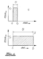
- an electronic control unit 3 with a microcontroller 9 which acts on the shape memory element 2. This is done in such a way that the control unit 3 supplies the shape memory element 2 with electrical power P as an influencing variable such that it (the influencing variable) assumes a certain value (within a predetermined range P 1 , P 2 ) (cf. FIG. 1) , This is additionally indicated by the current / time profiles shown in each case, which are explained in more detail in the context of FIG. 4.
- control unit 3 ensures that the shape memory element 2 for a certain time with a given Electricity is applied.
- the resulting one Coupling of power or performance that arises P therefore corresponds to a supply of heat for the shape memory element 2, this also from the control unit 3 specified and within a specified value range is held.
- Power P and heat supply depend on it directly (linearly) from each other, so that from a single Influencing variable (power or heat input) spoken can be.
- Variations of the current and / or the time duration t of the current application and thus the coupling of power (heat supply) as an influencing variable are now carried out as a function of external parameters influencing the influencing variable.
- these external parameters include in particular the prevailing ambient temperature T 1 , T 2 and the applied electrical voltage U, which is provided by a voltage source 4.
- a sensor 5 is used to measure the prevailing ambient temperature T 1 , T 2, which is an outside temperature sensor that is usually already present in a motor vehicle.
- the voltage source 4 also has a corresponding sensor 5 'for voltage measurement or, as shown in FIG. 3, is equipped with a voltage regulator 7 which specifies the voltage U in a fixed manner.
- Corresponding measured values for the voltage U and the temperature T 1 , T 2 are transferred to the control unit 3. On the basis of this input data, this then derives the influencing variable P for the application of the shape memory element 2.
- the influencing variable P ensures that, for example, if the desired change in length .DELTA.L is reached, the austenitic phase in the right part of FIG. 1 also reaches the temperature A F in the shape memory element 2 significantly.
- each temperature change ⁇ T in FIG. 1 corresponds to a specific electrical power P behind it, that is to say if it is part of the areas shown in FIG. 4, it becomes clear that the control unit 3 depends on the starting point or outside temperature T 1 or T 2 (cf. FIG. 1) must deliver a more or less large electrical power P to the shape memory element 2 so that the temperature A f is reliably reached.
- the respective areas P 1 and P 2 are dimensioned such that, starting with the associated temperature T 1 or T 2, a certain end temperature T E above the end temperature for the austenitic phase A f is reliably reached.
- a switch 6 can be recognized by an outer door handle or Inner door handle of a motor vehicle, which described Changes in length ⁇ L of the shape memory element 2 initiated.
- the associated switch signal from the Control unit 3 evaluated.
- the control unit 3 react to a remote control unit R (remote control). Both signals are from an input / output unit 8 processed and passed to the microcontroller 9, which is clocked by an oscillator 10.
- a voltage regulator 7 ensures that the microcontroller 9 with constant supply voltage from the voltage source 4 is supplied.
- the shape memory element 2 as an actuator 2 is also connected to the voltage source 4 via a switch, in the present case a FET transistor S. Via a connecting line 11 to the FET transistor or switch S, the microcontroller 9 ensures that the shape memory element 2 is only supplied with current I (t) within the time period between t 1 and t 2, which is shown in particular in FIG. 4. Before this, however, the voltage U of the voltage source 4 and also the outside temperature T 1 , T 2 have been detected by correspondingly indicated sensors 5, 5 'and transferred to the microcontroller 9 via an A / D converter 12. The same applies to a further sensor 13, which may recognize the completion of the adjusting movement of the adjusting device described or the position of a rotary latch.
- the voltage regulator 7, the oscillator 10, the A / D converter 12, the input / output unit 8 and the microcontroller 9 form the total in connection with the switch S.
- Control unit 3. The operation is as follows.
- a signal from the switch 6 or the remote control unit R leads, for example, to unlocking a rotary latch of a motor vehicle door lock first of all by querying the sensor 13 on the rotary latch. If this is closed, a corresponding unlocking routine can be run through.
- the ambient temperature T 1 , T 2 and the voltage U applied to the shape memory element 2 are determined with the aid of the sensors 5, 5 '.
- the microcontroller 9 or the control unit 3 calculates the required heat input or power input P 1 , P 2 in order to be able to reach the final temperature T E (see FIG. 1).
- the control unit 3 or the microcontroller 9 takes into account the fact that different currents flow at a predetermined voltage U depending on the prevailing ambient temperature T 1 or T 2 . This is expressed in Fig. 4.
- the low initial or ambient temperature T 1 corresponds to a relatively high current I 1 because the shape memory element 2 is "cold" and opposes the current with a low resistance.
- the resistance increases with increasing temperature, which is expressed in the reduced current I 2 if the start is made at the higher temperature T 2 .
- These temperature-dependent current values I 1 and I 2 are known and can be stored in the microcontroller 9 or a memory there and depend on the characteristic of the shape memory element 2.
- the control unit 3 or the microcontroller 9 taking into account the likewise predetermined voltage U, now calculates the required power P to be coupled in (hatched area in FIG. 4) in order to reliably determine the final temperature T E according to To be able to achieve Fig. 1.
- the control unit 3 or the microcontroller 9 thus specifies the influencing variable P or its value depending on the external parameters T 1 , T 2 , U. This value ensures that the shape memory element 2 has reached the temperature T E after the application.
- a pawl is unlocked with the aid of the shape memory element 2 which is now deflected by the amount .DELTA.L and which opens the rotary latch queried by means of the sensor 13.
- the sensor 13 delivers an unlocking signal to the microcontroller 9 when the unlocking has been completed.
- the respective power values P 1 , P 2 define the range within which the power P to be coupled in must be kept. This is because the power values P 1 , P 2 correspond to extreme values of the external parameters T 1 , T 2 and U.
Landscapes
- Engineering & Computer Science (AREA)
- Chemical & Material Sciences (AREA)
- Combustion & Propulsion (AREA)
- Mechanical Engineering (AREA)
- General Engineering & Computer Science (AREA)
- Lock And Its Accessories (AREA)
- Semiconductor Memories (AREA)
- Micromachines (AREA)
- Credit Cards Or The Like (AREA)
- Wire Bonding (AREA)
- Bidet-Like Cleaning Device And Other Flush Toilet Accessories (AREA)
Abstract
Description
Bei der das Formgedächtniselement beeinflussenden Einflussgröße handelt es sich in der Regel um die zugeführte elektrische Leistung. Diese wird von der Steuereinheit je nach herrschender und gemessener Außentemperatur als äußerer Parameter modifiziert. Ebenso sorgt die am Formgedächtniselement anliegende Spannung als äußerer Parameter für eine entsprechende Modifikation der seitens der Steuereinheit zugeführten elektrischen Leistung. Schließlich nimmt das Formgedächtniselement - wie bereits beschrieben - wenigstens zwei verschiedene Kristallstrukturen in Abhängigkeit von der Einflussgröße ein. Dabei korrespondiert die Ausbildung der unterschiedlichen Phasen jeweils zu Eckwerten der Einflussgröße. Diese Eckwerte der Einflussgröße definieren die minimale Reichweite des vorgegebenen Bereiches, innerhalb dessen die Steuereinheit den Wert der Einflussgröße hält.
- Fig. 1
- eine typische Weg-Temperatur-Kennlinie eines Formgedächtniselementes mit Zweiwegeffekt,
- Fig. 2
- die erfindungsgemäß eingesetzte Steuereinheit schematisch,
- Fig. 3
- ein detaillierteres Bild des Gegenstandes nach Fig. 2 und
- Fig. 4
- die Leistungsansteuerung des Formgedächtniselementes schematisch.
Claims (10)
- Stellvorrichtung, z. B. zur Ver-/Entriegelung von Kraftfahrzeug-Türverschlüssen (1), mit einem als Aktuator (2) ausgebildeten Formgedächtniselement (2), welches in Abhängigkeit von zumindest einer Einflussgröße (P) seine Gestalt reversibel ändert, und mit einer elektronischen Steuereinheit (3) zur Beaufschlagung des Aktuators (2), dadurch gekennzeichnet, dass die Steuereinheit (3) das Formgedächtniselement (2) so beaufschlagt, dass die Einflussgröße (P) einen vorgegebenen Wert annimmt.
- Stellvorrichtung nach Anspruch 1 dadurch gekennzeichnet, dass die Steuereinheit (3) den Wert der Einflussgröße (P) in Abhängigkeit von die Einflussgröße (P) beeinflussenden äußeren Parametern wie herrschende Umgebungstemperatur (T1, T2), anliegende elektrische Spannung (U), Stärke des Magnetfeldes etc. vorgibt.
- Stellvorrichtung nach Anspruch 1 oder 2, dadurch gekennzeichnet, dass der oder die äußeren Parameter (T1, T2; U) mittels eines oder mehrerer an die Steuereinheit (3) angeschlossener Sensoren (5, 5') erfasst werden.
- Stellvorrichtung nach einem der Ansprüche 1 bis 3, dadurch gekennzeichnet, dass die Steuereinheit (3) aufgrund der mit den Sensoren (5, 5') erfassten Messwerte einen Wert für die Einflussgröße (P) im Sinne einer Steuerung oder Regelung so vorgibt, dass dieser von den äußeren Parametern (T1, T2; U) beeinflusste Wert innerhalb eines vorgegebenen Bereiches (P1, P2) liegt.
- Stellvorrichtung nach einem der Ansprüche 1 bis 4, dadurch gekennzeichnet, dass das Formgedächtniselement (2) als durch Wärmezufuhr verformbare Formgedächtnislegierung ausgebildet ist.
- Stellvorrichtung nach einem der Ansprüche 1 bis 5, dadurch gekennzeichnet, dass es sich bei der Einflussgröße (P) um die dem Formgedächtniselement (2) zugeführte elektrische Leistung handelt.
- Stellvorrichtung nach einem der Ansprüche 1 bis 6, dadurch gekennzeichnet, dass die dem Formgedächtniselement (2) zugeführte elektrische Leistung (P) seitens der Steuereinheit (3) je nach herrschender und gemessener Außentemperatur (T1, T2) als äußerer Parameter modifiziert wird.
- Stellvorrichtung nach einem der Ansprüche 1 bis 7, dadurch gekennzeichnet, dass die dem Formgedächtniselement (2) zugeführte elektrische Leistung (P) seitens der Steuereinheit (3) je nach am Formgedächtniselement (2) anliegender Spannung (U) als äußerer Parameter modifiziert wird.
- Stellvorrichtung nach einem der Ansprüche 1 bis 8, dadurch gekennzeichnet, dass das Formgedächtniselement (2) wenigstens zwei verschiedene Kristallstrukturen in Abhängigkeit von der Einflussgröße (P) einnimmt.
- Stellvorrichtung nach einem der Ansprüche 1 bis 9, dadurch gekennzeichnet, dass die Ausbildung der unterschiedlichen Phasen des Formgedächtniselementes (2) jeweils zu Eckwerten der Einflussgröße (P) korrespondiert, welche den vorgegebenen Bereich (P1, P2) definieren, innerhalb dessen die Steuereinheit (3) den Wert der Einflussgröße (P) hält.
Applications Claiming Priority (2)
| Application Number | Priority Date | Filing Date | Title |
|---|---|---|---|
| DE10214398 | 2002-03-30 | ||
| DE10214398A DE10214398A1 (de) | 2002-03-30 | 2002-03-30 | Stellvorrichtung |
Publications (2)
| Publication Number | Publication Date |
|---|---|
| EP1350954A1 true EP1350954A1 (de) | 2003-10-08 |
| EP1350954B1 EP1350954B1 (de) | 2006-05-24 |
Family
ID=27816080
Family Applications (1)
| Application Number | Title | Priority Date | Filing Date |
|---|---|---|---|
| EP03006691A Expired - Lifetime EP1350954B1 (de) | 2002-03-30 | 2003-03-26 | Stellvorrichtung mit Formgedächtniselement |
Country Status (3)
| Country | Link |
|---|---|
| EP (1) | EP1350954B1 (de) |
| AT (1) | ATE327431T1 (de) |
| DE (2) | DE10214398A1 (de) |
Cited By (2)
| Publication number | Priority date | Publication date | Assignee | Title |
|---|---|---|---|---|
| EP1607628A1 (de) * | 2004-06-10 | 2005-12-21 | C.R.F. Società Consortile per Azioni | Verfahren und System zur Regelung von Aktuatoren aus Formgedächtnislegierungen |
| EP1767782A1 (de) * | 2005-09-23 | 2007-03-28 | Robert Bosch Gmbh | Verfahren zur Steuerung eines Formgedächtnislegierungaktor |
Families Citing this family (15)
| Publication number | Priority date | Publication date | Assignee | Title |
|---|---|---|---|---|
| DE102004047354A1 (de) * | 2004-09-29 | 2006-04-06 | Siemens Ag | Schaltungsanrordung umfassend wenigstens einen durch Zufuhr eines Strompulses oder Anlegen eines Magnetfelds in seiner Form veränderbaren Aktor |
| US7581706B2 (en) | 2006-06-26 | 2009-09-01 | Lear Corporation | Shape memory alloy (SMA) system |
| DE102006030140A1 (de) * | 2006-06-29 | 2008-01-03 | Meidinger, Norbert | Aktuator basierend auf einer Formgedächtnislegierung |
| DE102008054900B4 (de) | 2008-12-18 | 2011-12-15 | Faurecia Innenraum Systeme Gmbh | Aktuatorvorrichtung |
| DE102009060464A1 (de) | 2009-12-24 | 2011-06-30 | Kiekert AG, 42579 | Schließeinrichtung mit SMA-Glied |
| DE102010003523A1 (de) | 2010-03-31 | 2011-10-06 | Kiekert Ag | Verriegelungseinrichtung für ein Kraftfahrzeug |
| DE102010040522A1 (de) | 2010-09-09 | 2012-03-15 | Kiekert Ag | Stellantrieb für ein Kraftfahrzeug |
| DE102010003545A1 (de) | 2010-03-31 | 2011-10-06 | Kiekert Ag | Stellantrieb für ein Kraftfahrzeug |
| WO2011120719A1 (de) | 2010-03-31 | 2011-10-06 | Kiekert Ag | Stellantrieb für ein kraftfahrzeug sowie verriegelungseinrichtung nebst verfahren |
| DE102010029446A1 (de) | 2010-05-28 | 2011-12-01 | Kiekert Ag | Stellantrieb für ein Kraftfahrzeug |
| DE202010012379U1 (de) | 2010-09-09 | 2011-12-12 | Kiekert Ag | Stellantrieb für ein Kraftfahrzeug |
| EP2576264B1 (de) | 2010-05-28 | 2016-01-13 | Kiekert Aktiengesellschaft | Stellantrieb für ein kraftfahrzeug |
| DE202011000738U1 (de) | 2011-03-31 | 2012-07-05 | Kiekert Ag | Verriegelungseinrichtung |
| DE102011006475A1 (de) | 2011-03-31 | 2012-10-04 | Kiekert Ag | System mit Stellantrieb für ein Kraftfahrzeug |
| DE102011076560A1 (de) | 2011-05-26 | 2012-11-29 | Kiekert Ag | Stellantrieb für ein Kraftfahrzeug und Verfahren |
Citations (4)
| Publication number | Priority date | Publication date | Assignee | Title |
|---|---|---|---|---|
| US4930494A (en) * | 1988-03-09 | 1990-06-05 | Olympus Optical Co., Ltd. | Apparatus for bending an insertion section of an endoscope using a shape memory alloy |
| US5685148A (en) * | 1994-11-14 | 1997-11-11 | Landis & Gyr Technology Innovation Ag | Drive apparatus |
| DE19738494A1 (de) * | 1996-09-13 | 1998-03-19 | Volkswagen Ag | Antriebsmotor |
| US5763979A (en) * | 1996-02-29 | 1998-06-09 | The United States Of America As Represented By The Secretary Of The Navy | Actuation system for the control of multiple shape memory alloy elements |
-
2002
- 2002-03-30 DE DE10214398A patent/DE10214398A1/de not_active Withdrawn
-
2003
- 2003-03-26 DE DE50303421T patent/DE50303421D1/de not_active Expired - Lifetime
- 2003-03-26 EP EP03006691A patent/EP1350954B1/de not_active Expired - Lifetime
- 2003-03-26 AT AT03006691T patent/ATE327431T1/de not_active IP Right Cessation
Patent Citations (4)
| Publication number | Priority date | Publication date | Assignee | Title |
|---|---|---|---|---|
| US4930494A (en) * | 1988-03-09 | 1990-06-05 | Olympus Optical Co., Ltd. | Apparatus for bending an insertion section of an endoscope using a shape memory alloy |
| US5685148A (en) * | 1994-11-14 | 1997-11-11 | Landis & Gyr Technology Innovation Ag | Drive apparatus |
| US5763979A (en) * | 1996-02-29 | 1998-06-09 | The United States Of America As Represented By The Secretary Of The Navy | Actuation system for the control of multiple shape memory alloy elements |
| DE19738494A1 (de) * | 1996-09-13 | 1998-03-19 | Volkswagen Ag | Antriebsmotor |
Cited By (2)
| Publication number | Priority date | Publication date | Assignee | Title |
|---|---|---|---|---|
| EP1607628A1 (de) * | 2004-06-10 | 2005-12-21 | C.R.F. Società Consortile per Azioni | Verfahren und System zur Regelung von Aktuatoren aus Formgedächtnislegierungen |
| EP1767782A1 (de) * | 2005-09-23 | 2007-03-28 | Robert Bosch Gmbh | Verfahren zur Steuerung eines Formgedächtnislegierungaktor |
Also Published As
| Publication number | Publication date |
|---|---|
| EP1350954B1 (de) | 2006-05-24 |
| DE10214398A1 (de) | 2003-10-16 |
| DE50303421D1 (de) | 2006-06-29 |
| ATE327431T1 (de) | 2006-06-15 |
Similar Documents
| Publication | Publication Date | Title |
|---|---|---|
| EP1350954B1 (de) | Stellvorrichtung mit Formgedächtniselement | |
| DE10063080A1 (de) | Aktorsteuerung und zugehöriges Verfahren | |
| DE102007053741B4 (de) | Elektronisches Schließ-System mit Memorymetall-Aktor | |
| EP1540431B1 (de) | Verfahren zum regeln des stroms durch ein elektromagnetisches stellglied | |
| DE19848950A1 (de) | Vorrichtung zur Konstantsteuerung piezoelektrischer Aktuatoren für Kraftstoffeinspritzsysteme | |
| DE2313240C3 (de) | Auf Temperaturänderungen ansprechende Betätigungsvorrichtung | |
| WO2011048071A1 (de) | Vorrichtung zur ansteuerung des aktuators eines einspritzventils einer verbrennungskraftmaschine | |
| EP2312187A1 (de) | Vorrichtung mit einem linear verstellbaren Hubteil | |
| DE2939586A1 (de) | Verfahren und anordnung zur regelupng der wassertemperatur von warmwasser-flaechenheizungen | |
| EP1375882B1 (de) | Verfahren zum Betreiben einer Brennkraftmaschine insbesondere eines Kraftfahrzeugs | |
| WO2005040582A2 (de) | Diagnoseverfahren für einen elektromechanischen aktor | |
| DE19949136A1 (de) | Betätigungsaufsatz für ein Ventil | |
| DE102022100482A1 (de) | Verfahren zur Bestimmung einer Stellungsänderung eines mit einem Elektromotor mechanisch gekoppelten Bauteils | |
| WO2013044946A1 (de) | Aktuator zur erzeugung von stellbewegungen | |
| DE102013225479B4 (de) | Ventilvorrichtung für eine Entwässerungsleitung einer Turbine, Entwässerungseinheit sowie Turbine | |
| DE102008031584B4 (de) | Anordnung zum Verstellen eines Ventils | |
| DE10351141A1 (de) | Verfahren zur Kompensation von Injektorstreuungen bei Einspritzventilen | |
| EP1550353A2 (de) | Verbundkörper und verfahren zu dessen herstellung | |
| DE102006006241A1 (de) | Linearbewegungsaktuator | |
| DE102005049779A1 (de) | Schaltungsanordnung zum Betreiben eines als Heizelement eingesetzten PTC-Elements | |
| DE10242791A1 (de) | Verfahren zur Ermittlung eines mittleren Stroms durch ein elektromagnetisches Stellglied | |
| DE19933956A1 (de) | Elektrisches Bauelement, insbesondere Schaltelement | |
| DE19947266A1 (de) | Hydraulische Servolenkung mit Lenkungsdämpfer | |
| EP2096344B1 (de) | Heizkörperthermostat mit einem Stelltrieb | |
| DE3614011A1 (de) | Absperrorgan mit schieber |
Legal Events
| Date | Code | Title | Description |
|---|---|---|---|
| PUAI | Public reference made under article 153(3) epc to a published international application that has entered the european phase |
Free format text: ORIGINAL CODE: 0009012 |
|
| AK | Designated contracting states |
Kind code of ref document: A1 Designated state(s): AT BE BG CH CY CZ DE DK EE ES FI FR GB GR HU IE IT LI LU MC NL PT RO SE SI SK TR |
|
| AX | Request for extension of the european patent |
Extension state: AL LT LV MK |
|
| 17P | Request for examination filed |
Effective date: 20040401 |
|
| AKX | Designation fees paid |
Designated state(s): AT BE BG CH CY CZ DE DK EE ES FI FR GB GR HU IE IT LI LU MC NL PT RO SE SI SK TR |
|
| 17Q | First examination report despatched |
Effective date: 20041011 |
|
| GRAP | Despatch of communication of intention to grant a patent |
Free format text: ORIGINAL CODE: EPIDOSNIGR1 |
|
| GRAS | Grant fee paid |
Free format text: ORIGINAL CODE: EPIDOSNIGR3 |
|
| GRAA | (expected) grant |
Free format text: ORIGINAL CODE: 0009210 |
|
| AK | Designated contracting states |
Kind code of ref document: B1 Designated state(s): AT BE BG CH CY CZ DE DK EE ES FI FR GB GR HU IE IT LI LU MC NL PT RO SE SI SK TR |
|
| PG25 | Lapsed in a contracting state [announced via postgrant information from national office to epo] |
Ref country code: IT Free format text: LAPSE BECAUSE OF FAILURE TO SUBMIT A TRANSLATION OF THE DESCRIPTION OR TO PAY THE FEE WITHIN THE PRESCRIBED TIME-LIMIT;WARNING: LAPSES OF ITALIAN PATENTS WITH EFFECTIVE DATE BEFORE 2007 MAY HAVE OCCURRED AT ANY TIME BEFORE 2007. THE CORRECT EFFECTIVE DATE MAY BE DIFFERENT FROM THE ONE RECORDED. Effective date: 20060524 Ref country code: SI Free format text: LAPSE BECAUSE OF FAILURE TO SUBMIT A TRANSLATION OF THE DESCRIPTION OR TO PAY THE FEE WITHIN THE PRESCRIBED TIME-LIMIT Effective date: 20060524 Ref country code: NL Free format text: LAPSE BECAUSE OF FAILURE TO SUBMIT A TRANSLATION OF THE DESCRIPTION OR TO PAY THE FEE WITHIN THE PRESCRIBED TIME-LIMIT Effective date: 20060524 Ref country code: IE Free format text: LAPSE BECAUSE OF FAILURE TO SUBMIT A TRANSLATION OF THE DESCRIPTION OR TO PAY THE FEE WITHIN THE PRESCRIBED TIME-LIMIT Effective date: 20060524 Ref country code: RO Free format text: LAPSE BECAUSE OF FAILURE TO SUBMIT A TRANSLATION OF THE DESCRIPTION OR TO PAY THE FEE WITHIN THE PRESCRIBED TIME-LIMIT Effective date: 20060524 Ref country code: FI Free format text: LAPSE BECAUSE OF FAILURE TO SUBMIT A TRANSLATION OF THE DESCRIPTION OR TO PAY THE FEE WITHIN THE PRESCRIBED TIME-LIMIT Effective date: 20060524 Ref country code: SK Free format text: LAPSE BECAUSE OF FAILURE TO SUBMIT A TRANSLATION OF THE DESCRIPTION OR TO PAY THE FEE WITHIN THE PRESCRIBED TIME-LIMIT Effective date: 20060524 Ref country code: CZ Free format text: LAPSE BECAUSE OF FAILURE TO SUBMIT A TRANSLATION OF THE DESCRIPTION OR TO PAY THE FEE WITHIN THE PRESCRIBED TIME-LIMIT Effective date: 20060524 Ref country code: GB Free format text: LAPSE BECAUSE OF FAILURE TO SUBMIT A TRANSLATION OF THE DESCRIPTION OR TO PAY THE FEE WITHIN THE PRESCRIBED TIME-LIMIT Effective date: 20060524 |
|
| REG | Reference to a national code |
Ref country code: GB Ref legal event code: FG4D Free format text: NOT ENGLISH |
|
| REG | Reference to a national code |
Ref country code: CH Ref legal event code: EP |
|
| REG | Reference to a national code |
Ref country code: IE Ref legal event code: FG4D Free format text: LANGUAGE OF EP DOCUMENT: GERMAN |
|
| REF | Corresponds to: |
Ref document number: 50303421 Country of ref document: DE Date of ref document: 20060629 Kind code of ref document: P |
|
| PG25 | Lapsed in a contracting state [announced via postgrant information from national office to epo] |
Ref country code: SE Free format text: LAPSE BECAUSE OF FAILURE TO SUBMIT A TRANSLATION OF THE DESCRIPTION OR TO PAY THE FEE WITHIN THE PRESCRIBED TIME-LIMIT Effective date: 20060824 Ref country code: DK Free format text: LAPSE BECAUSE OF FAILURE TO SUBMIT A TRANSLATION OF THE DESCRIPTION OR TO PAY THE FEE WITHIN THE PRESCRIBED TIME-LIMIT Effective date: 20060824 |
|
| PG25 | Lapsed in a contracting state [announced via postgrant information from national office to epo] |
Ref country code: ES Free format text: LAPSE BECAUSE OF FAILURE TO SUBMIT A TRANSLATION OF THE DESCRIPTION OR TO PAY THE FEE WITHIN THE PRESCRIBED TIME-LIMIT Effective date: 20060904 |
|
| PG25 | Lapsed in a contracting state [announced via postgrant information from national office to epo] |
Ref country code: PT Free format text: LAPSE BECAUSE OF FAILURE TO SUBMIT A TRANSLATION OF THE DESCRIPTION OR TO PAY THE FEE WITHIN THE PRESCRIBED TIME-LIMIT Effective date: 20061024 |
|
| NLV1 | Nl: lapsed or annulled due to failure to fulfill the requirements of art. 29p and 29m of the patents act | ||
| GBV | Gb: ep patent (uk) treated as always having been void in accordance with gb section 77(7)/1977 [no translation filed] |
Effective date: 20060524 |
|
| REG | Reference to a national code |
Ref country code: IE Ref legal event code: FD4D |
|
| PLBE | No opposition filed within time limit |
Free format text: ORIGINAL CODE: 0009261 |
|
| STAA | Information on the status of an ep patent application or granted ep patent |
Free format text: STATUS: NO OPPOSITION FILED WITHIN TIME LIMIT |
|
| 26N | No opposition filed |
Effective date: 20070227 |
|
| EN | Fr: translation not filed | ||
| REG | Reference to a national code |
Ref country code: CH Ref legal event code: PL |
|
| BERE | Be: lapsed |
Owner name: KIEKERT A.G. Effective date: 20070331 |
|
| PG25 | Lapsed in a contracting state [announced via postgrant information from national office to epo] |
Ref country code: BE Free format text: LAPSE BECAUSE OF NON-PAYMENT OF DUE FEES Effective date: 20070331 |
|
| PG25 | Lapsed in a contracting state [announced via postgrant information from national office to epo] |
Ref country code: MC Free format text: LAPSE BECAUSE OF NON-PAYMENT OF DUE FEES Effective date: 20070331 |
|
| PG25 | Lapsed in a contracting state [announced via postgrant information from national office to epo] |
Ref country code: LI Free format text: LAPSE BECAUSE OF NON-PAYMENT OF DUE FEES Effective date: 20070331 Ref country code: CH Free format text: LAPSE BECAUSE OF NON-PAYMENT OF DUE FEES Effective date: 20070331 |
|
| PG25 | Lapsed in a contracting state [announced via postgrant information from national office to epo] |
Ref country code: FR Free format text: LAPSE BECAUSE OF FAILURE TO SUBMIT A TRANSLATION OF THE DESCRIPTION OR TO PAY THE FEE WITHIN THE PRESCRIBED TIME-LIMIT Effective date: 20070309 Ref country code: GR Free format text: LAPSE BECAUSE OF FAILURE TO SUBMIT A TRANSLATION OF THE DESCRIPTION OR TO PAY THE FEE WITHIN THE PRESCRIBED TIME-LIMIT Effective date: 20060825 |
|
| PG25 | Lapsed in a contracting state [announced via postgrant information from national office to epo] |
Ref country code: AT Free format text: LAPSE BECAUSE OF NON-PAYMENT OF DUE FEES Effective date: 20070326 Ref country code: BG Free format text: LAPSE BECAUSE OF FAILURE TO SUBMIT A TRANSLATION OF THE DESCRIPTION OR TO PAY THE FEE WITHIN THE PRESCRIBED TIME-LIMIT Effective date: 20060824 |
|
| PG25 | Lapsed in a contracting state [announced via postgrant information from national office to epo] |
Ref country code: EE Free format text: LAPSE BECAUSE OF FAILURE TO SUBMIT A TRANSLATION OF THE DESCRIPTION OR TO PAY THE FEE WITHIN THE PRESCRIBED TIME-LIMIT Effective date: 20060524 |
|
| PG25 | Lapsed in a contracting state [announced via postgrant information from national office to epo] |
Ref country code: FR Free format text: LAPSE BECAUSE OF FAILURE TO SUBMIT A TRANSLATION OF THE DESCRIPTION OR TO PAY THE FEE WITHIN THE PRESCRIBED TIME-LIMIT Effective date: 20060524 |
|
| PG25 | Lapsed in a contracting state [announced via postgrant information from national office to epo] |
Ref country code: CY Free format text: LAPSE BECAUSE OF FAILURE TO SUBMIT A TRANSLATION OF THE DESCRIPTION OR TO PAY THE FEE WITHIN THE PRESCRIBED TIME-LIMIT Effective date: 20060524 Ref country code: LU Free format text: LAPSE BECAUSE OF NON-PAYMENT OF DUE FEES Effective date: 20070326 |
|
| PG25 | Lapsed in a contracting state [announced via postgrant information from national office to epo] |
Ref country code: TR Free format text: LAPSE BECAUSE OF FAILURE TO SUBMIT A TRANSLATION OF THE DESCRIPTION OR TO PAY THE FEE WITHIN THE PRESCRIBED TIME-LIMIT Effective date: 20060524 Ref country code: HU Free format text: LAPSE BECAUSE OF FAILURE TO SUBMIT A TRANSLATION OF THE DESCRIPTION OR TO PAY THE FEE WITHIN THE PRESCRIBED TIME-LIMIT Effective date: 20061125 |
|
| PGFP | Annual fee paid to national office [announced via postgrant information from national office to epo] |
Ref country code: DE Payment date: 20170327 Year of fee payment: 15 |
|
| REG | Reference to a national code |
Ref country code: DE Ref legal event code: R119 Ref document number: 50303421 Country of ref document: DE |
|
| PG25 | Lapsed in a contracting state [announced via postgrant information from national office to epo] |
Ref country code: DE Free format text: LAPSE BECAUSE OF NON-PAYMENT OF DUE FEES Effective date: 20181002 |