EP1350700A2 - Antrieb eines Scheibenwischers - Google Patents
Antrieb eines Scheibenwischers Download PDFInfo
- Publication number
- EP1350700A2 EP1350700A2 EP02023347A EP02023347A EP1350700A2 EP 1350700 A2 EP1350700 A2 EP 1350700A2 EP 02023347 A EP02023347 A EP 02023347A EP 02023347 A EP02023347 A EP 02023347A EP 1350700 A2 EP1350700 A2 EP 1350700A2
- Authority
- EP
- European Patent Office
- Prior art keywords
- wiper
- drive
- motor
- storage spring
- spring
- Prior art date
- Legal status (The legal status is an assumption and is not a legal conclusion. Google has not performed a legal analysis and makes no representation as to the accuracy of the status listed.)
- Granted
Links
- 230000002441 reversible effect Effects 0.000 claims abstract description 25
- 230000006835 compression Effects 0.000 claims description 3
- 238000007906 compression Methods 0.000 claims description 3
- 238000003466 welding Methods 0.000 claims description 2
- 230000005484 gravity Effects 0.000 description 3
- 230000036316 preload Effects 0.000 description 2
- 230000001133 acceleration Effects 0.000 description 1
- 230000007423 decrease Effects 0.000 description 1
- 230000000694 effects Effects 0.000 description 1
- 230000005611 electricity Effects 0.000 description 1
- 238000009434 installation Methods 0.000 description 1
- 238000000034 method Methods 0.000 description 1
- 230000003319 supportive effect Effects 0.000 description 1
Images


Classifications
-
- B—PERFORMING OPERATIONS; TRANSPORTING
- B60—VEHICLES IN GENERAL
- B60S—SERVICING, CLEANING, REPAIRING, SUPPORTING, LIFTING, OR MANOEUVRING OF VEHICLES, NOT OTHERWISE PROVIDED FOR
- B60S1/00—Cleaning of vehicles
- B60S1/02—Cleaning windscreens, windows or optical devices
- B60S1/04—Wipers or the like, e.g. scrapers
- B60S1/32—Wipers or the like, e.g. scrapers characterised by constructional features of wiper blade arms or blades
- B60S1/34—Wiper arms; Mountings therefor
- B60S1/3425—Constructional aspects of the arm
- B60S1/3443—Wiper shafts
-
- B—PERFORMING OPERATIONS; TRANSPORTING
- B60—VEHICLES IN GENERAL
- B60S—SERVICING, CLEANING, REPAIRING, SUPPORTING, LIFTING, OR MANOEUVRING OF VEHICLES, NOT OTHERWISE PROVIDED FOR
- B60S1/00—Cleaning of vehicles
- B60S1/02—Cleaning windscreens, windows or optical devices
- B60S1/04—Wipers or the like, e.g. scrapers
- B60S1/06—Wipers or the like, e.g. scrapers characterised by the drive
- B60S1/16—Means for transmitting drive
- B60S1/18—Means for transmitting drive mechanically
- B60S1/185—Means for transmitting drive mechanically with means for stopping or setting the wipers at their limit of movement
-
- B—PERFORMING OPERATIONS; TRANSPORTING
- B60—VEHICLES IN GENERAL
- B60S—SERVICING, CLEANING, REPAIRING, SUPPORTING, LIFTING, OR MANOEUVRING OF VEHICLES, NOT OTHERWISE PROVIDED FOR
- B60S1/00—Cleaning of vehicles
- B60S1/02—Cleaning windscreens, windows or optical devices
- B60S1/04—Wipers or the like, e.g. scrapers
- B60S1/32—Wipers or the like, e.g. scrapers characterised by constructional features of wiper blade arms or blades
- B60S1/34—Wiper arms; Mountings therefor
- B60S1/3488—Means for mounting wiper arms onto the vehicle
- B60S1/3493—Means for mounting the wiper shaft in the wiper bearing
-
- B—PERFORMING OPERATIONS; TRANSPORTING
- B60—VEHICLES IN GENERAL
- B60S—SERVICING, CLEANING, REPAIRING, SUPPORTING, LIFTING, OR MANOEUVRING OF VEHICLES, NOT OTHERWISE PROVIDED FOR
- B60S1/00—Cleaning of vehicles
- B60S1/02—Cleaning windscreens, windows or optical devices
- B60S1/04—Wipers or the like, e.g. scrapers
- B60S1/32—Wipers or the like, e.g. scrapers characterised by constructional features of wiper blade arms or blades
- B60S1/34—Wiper arms; Mountings therefor
- B60S1/3488—Means for mounting wiper arms onto the vehicle
- B60S1/3495—Means for mounting the drive mechanism to the wiper shaft
Definitions
- the invention relates to a drive for a windshield wiper according to the preamble of claim 1.
- Wiper systems with several windshield wipers for motor vehicles are attached to the vehicle body directly or indirectly via a circuit board with their wiper bearings.
- the board comprises a motor board which carries a wiper drive with a wiper motor.
- An output shaft of the wiper motor drives a wiper shaft for each wiper via a lever gear. This is pivotally mounted in a bearing housing of the wiper bearing.
- the windshield wipers are increasingly driven by a reversible wiper motor, it being possible for one wiper motor to drive a plurality of windshield wipers together, or a wiper motor can be assigned to each windshield wiper.
- the last alternative is particularly suitable for reverse wiping systems, in which the wiper bearings are arranged as close as possible to the side of the vehicle.
- the wiping area of a windshield wiper is limited by two reversing positions, the lower reversing position may coincide with a parking position or be slightly above the parking position.
- the windshield wiper In the park position, the windshield wiper is in the lowest position to the bonnet during breaks in operation, usually in a so-called hood gap between a bonnet and a windshield.
- the wiper moves from the lower reversing position up to the upper reversing position and then back again.
- the movement of the windshield wiper in the swivel direction to the upper reversing position is supported, for example, by the oncoming wind, but in turn made more difficult by a greater weight, while the windshield wiper must be moved in the opposite swivel direction against the wind, but the weight is directed in the swivel direction.
- different resistances act on the windshield wiper, which require different drive torques of the wiper motor, which must be designed according to the greatest moment to be expected and is therefore oversized in some operating states.
- a wiper drive is known from DE 198 24 640 A1, which to balance the drive torque of the wiper motor has passive biasing element.
- the wiper drive is mainly for a windshield wiper with a four-bar linkage intended. Since such wipers in the Usually have a large weight, the greatest drive torque is generated in this case at the beginning of the upward movement.
- the biasing element is a storage spring, the one end with a lever of the four-bar linkage connected while the other end, for example is attached to the board.
- the spring in Shape of a tension spring, is tensioned in the lower reversing position, so they start the upward movement especially supported.
- the tension spring is relieved during the wiping movement and just before the top reverse position so that they slow down and reverse the Windshield wipers supported at this reversal position and counteracts the weight during the downward movement.
- the tension spring has a relatively large one in the park position Preload and exerts a torque on the wiper drive from that during the breaks between self-locking the engine gearbox, e.g. a worm gear supports.
- Planetary gears are increasingly being used in new types of wiper drives used, which have a good efficiency, but usually have no self-locking. For such
- the spring is not suitable for drives because it Windshield wipers from its parking position towards the upper reverse position adjusted.
- the storage spring is arranged so that in the parking position of a wiper blade, it is not worth mentioning Torque on a drive element of a wiper drive exercises so that the wiper drive in this position, which the windshield wiper takes during the breaks, no holding force has to be exerted and therefore the spring is suitable for applications with all motor gearboxes.
- the storage spring is expediently in a spring housing of a bearing housing and is supported by a End there while the other end is on a driver one Wiper shaft is attached.
- the park position is the Spring loaded under pressure. Because the resulting Force runs approximately through the swivel axis of the wiper shaft, it does not exert any torque or no significant torque the wiper shaft. If the resulting force in the Parking position is a short distance from the swivel axis, the starting torque of the wiper motor is small counteracting torque that the wiper safe against possible interference during the breaks stops in the parking position.
- the spring preload supports the wiper motor again, so the dwell in the reverse position is shortened and that to accelerate the wiper required wiper motor drive torque reduced becomes. If the wiper shaft reaches the lower reversing position again, is the spring loaded under pressure, the wiper is braked and the wiper motor starts if the direction is reversed, support is provided.
- the lower reversing position can coincide with the parking position. Often this is slightly below the lower reverse position and is only started when the wiper system is turned off.
- the storage spring stores the energy from inertia the wiper in front of the reversing positions and sets They are released after the reversal positions, so that to accelerate initially very high torque significantly reduced and overall the moment curve over the swivel angle advantageously becomes flatter and symmetrical.
- the wiper motor can be dimensioned smaller and uses less Electricity.
- the wiper motor can be controlled more precisely, because in the reverse positions against a defined force is approached. It may even be a simplified one Control or electronics conceivable.
- the storage spring can also be attached to another drive element, for example an engine crank or a drive crank be arranged.
- the preloaded spring exercises a supportive one according to the principle described above Force on this drive element.
- the output shaft of the wiper motor via a motor crank and a rotary thrust joint with a drive crank on the wiper shaft connected, the storage spring at the end of the engine crank attacks, which points to the rotary slide joint, and in the park position acts approximately in the longitudinal direction of the engine crank, while in the top reverse position of the wiper blade is tangent to the circle of motion of the end of the engine crank.
- a drive is very compact, everyone A wiper motor is assigned to the wiper.
- the wiper motor expediently the wiper shaft in its housing stored approximately parallel to the output shaft of the wiper motor is a compact unit that is revealing in the tight space behind a bulkhead Motor vehicle can be placed.
- wiper motors come with worm gears Planetary gearboxes used in the Usually a high level of efficiency, but no self-locking have.
- the spring in the park position of the wiper blade exerts no torque on the drive element. Since at the resulting version in the parking position the resulting Force of the storage spring in the direction of the engine crank supports the output shaft, it generates no force component in the circumferential direction and therefore no torque on the drive.
- the storage spring First when the engine crank is moved out of the park position, the storage spring generates a force component in the circumferential direction, by which the torque of the wiper motor is supported becomes.
- the spring is in an intermediate position relaxes and becomes on the rest of the pivoting motion of the engine crank biased on train, causing inertial forces the windshield wiper to the top dead center position and after top dead center acceleration the wiper is supported.
- the storage spring expediently on the movement circle of the end of the engine crank guided.
- a storage spring which is in a reverse position, a compression bias and in the other reverse position, a tension has two storage springs provided only in Area of reversal positions take effect and apply pressure are biased. They act on a drive crank of the wiper shaft, and that at the end that over the rotary slide joint protrudes. At least in the parking position resulting force of the spring approximately parallel to the engine crank, so that there is no force component on the engine crank is generated in the circumferential direction, and thus on the output shaft no torque acts.
- the spring in the field of upper reverse position can be arranged in the same way. she but can also be so inclined in the upper reversing position Engine crank run that they always, if only a little Torque generated on the output shaft.
- a wiper bearing 10 comprises a bearing housing 12 in which one Wiper shaft 14 is pivotally mounted (Fig. 1). This will via a crank 22 with a ball joint pin 24 via a Lever gear, not shown, also from a shown reversible wiper motor driven.
- the wiper shaft 14 In In the axial direction, the wiper shaft 14 is supported by a Thrust washer 18 and a retaining ring 20 on the bearing housing 12 and is sealed by a seal 16.
- the bearing housing 12 is tubular and surrounds the Wiper shaft 14 (Fig. 2). In a limited area it is Bearing housing 12 reinforced so that there is enough space for a spring housing 26 exists in which a storage spring 28 is housed is. This is detachable at one end on a driver 34 attached to the wiper shaft 14 for example is attached by spot welding while engaging with the supports the other end on the spring housing 26. In the spring housing 26 the storage spring 28 is attached to a cover 30, the an opening 32 for threading the storage spring 28 closes.
- the wiper shaft 14 should be that shown in FIG. 2 Have position so that the storage spring 28th easily attached to the driver 34, for example clipped can be.
- the storage spring 28 is in the assembled state biased to pressure, the resulting force 38 approximately runs through the pivot axis 36 of the wiper shaft 14, so that no or no significant torque on the wiper shaft 14 is exercised. This position corresponds to one Parking position of the wiper.
- the wiper shaft 14 After a slight pivoting movement of the wiper shaft 14 the wiper shaft 14 reaches the so-called lower reversing position 60 and the resulting force 38 of the spring 28 is increasingly tangential to the wiper shaft 14. It generates a torque resulting from the resulting force 38 and the distance between it and the pivot axis 36 results and supports the pivoting movement of the wiper shaft 14, whereby the torque to be applied by the wiper motor is reduced. Change while swiveling the size and distance of the resulting force 38. In a first phase in which the gravity of the wipers a relatively large torque on the wiper shaft 14 exerts, the distance 40 increases rapidly while the pressure bias of the spring 28, the resulting force 38 slowly decreases.
- the support torque therefore reaches quickly reaches its maximum and then falls to a middle position to zero in which the spring springs relax has (Fig. 3).
- the storage spring 28 becomes the upper reversing position 62 biased on train, causing the resulting force 38 to be their Reverses direction and their distance 40 to the pivot axis 36 slowly increases to a maximum that it is in the upper reversing position 62 reached, in which the storage spring 28 approximately extends tangentially to the wiper shaft 14 (FIG. 4).
- the storage spring 28 can store energy according to the top Reverse position 62 to accelerate the wiper against the forces of the airstream are used. After the middle position, in which the supporting moment returns to zero because the spring 28 relaxes again the spring 28 biased back to pressure, the Wiper motor due to the increasing torque of gravity and the inertial forces are supported.
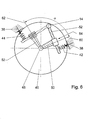
- the wiper motor 5 has a wiper motor with a integrated wiper shaft 14, which is in a view an engine cover 46 is shown.
- the wiper shaft 14 is driven by an output shaft 48 of the wiper motor Engine crank 50, a rotary thrust joint 54 and a drive crank 52 instinctively connected.
- the rotary thrust joint 54 is made essentially of an articulated with the engine crank 50 connected sleeve which on the drive crank 52 in the longitudinal direction is slidably mounted.
- the engine crank 50 will from the wiper motor between a parking position 64 or a lower reverse position 60 and an upper reverse position 62 moved back and forth over a swivel angle range ⁇ .
- the lower reversing position 60 can be in the parking position 64 match or slightly to the top reverse position 62 be staggered.
- the storage spring 56 is open in the lower parking position 60 Pressure biased, the resulting force 38 in the longitudinal direction the engine crank 50 acts so that no force component acts in the circumferential direction and a torque on the output shaft 48 or generated on the wiper shaft 14.
- the Parking position 64 close the engine crank 50 and the drive crank 52 a right angle.
- FIG. 6 differs from the embodiment 5 in that instead of a storage spring 56 in the area of parking position 64 each have a spring 42, 44 arranged in the area of the reversal positions 60 and 62 is. They are both compression springs that are only in the reverse position 60 and 62 each on the end of the drive crank 52 act, which protrudes above the rotary slide joint 54.
- the storage spring 44 in the region of the upper reversing position 62 and in particular the storage spring 42 in the area the parking position 64 are arranged so that their resulting Force 38 when the reversing positions 60 and 62 are reached runs approximately parallel to the engine crank 50, so that no or no significant torque on the output shaft 48 or the wiper shaft 14 is exerted.
- the positions of the engine crank 50 and the drive crank 52 are shown in dashed lines in the upper reversing position 62.
Landscapes
- Engineering & Computer Science (AREA)
- Mechanical Engineering (AREA)
- Connection Of Motors, Electrical Generators, Mechanical Devices, And The Like (AREA)
- Transmission Devices (AREA)
Abstract
Description
Der Wischbereich eines Scheibenwischers wird durch zwei Umkehrpositionen begrenzt, wobei die untere Umkehrposition mit einer Parkposition zusammenfallen kann oder geringfügig oberhalb der Parkposition liegt. In der Parkposition befindet sich der Scheibenwischer während der Betriebspausen in der tiefsten Stellung zur Motorhaube, meistens in einer so genannten Haubenspalte zwischen einer Motorhaube und einer Windschutzscheibe. Während eines Wischvorgangs bewegt sich der Scheibenwischer von der unteren Umkehrposition aus nach oben in die obere Umkehrposition und anschließend wieder zurück. Dabei wird die Bewegung des Scheibenwischers in Schwenkrichtung zur oberen Umkehrposition beispielsweise durch den anströmenden Fahrtwind unterstützt, aber wiederum durch eine größere Gewichtskraft erschwert, während der Scheibenwischer in umgekehrter Schwenkrichtung gegen den Fahrtwind bewegt werden muss, die Gewichtskraft aber in Schwenkrichtung gerichtet ist. Somit wirken auf den Scheibenwischer je nach Schwenkrichtung unterschiedliche Widerstände, die unterschiedliche Antriebsmomente des Wischermotors erfordern, wobei dieser nach dem größten zu erwartenden Moment ausgelegt werden muss und demnach in einigen Betriebszuständen überdimensioniert ist.
- Fig. 1
- eine schematische Darstellung eines Wischerlagers,
- Fig. 2
- einen Schnitt durch ein Wischerlager in einer Parkposition gemäß einer Linie II-II in Fig. 1,
- Fig. 3
- einen Schnitt gemäß Fig. 2 in einer Zwischenstellung,
- Fig. 4
- einen Schnitt gemäß Fig. 2 in einer oberen Umkehrposition,
- Fig. 5
- eine schematische Frontansicht eines Wischerantriebs und
- Fig. 6
- eine Variante zu Fig. 5.
- 10
- Wischerlager
- 12
- Lagergehäuse
- 14
- Wischerwelle
- 16
- Dichtung
- 18
- Anlaufscheibe
- 20
- Sicherungsring
- 22
- Kurbel
- 24
- Kugelgelenkzapfen
- 26
- Federgehäuse
- 28
- Speicherfeder
- 30
- Deckel
- 32
- Öffnung
- 34
- Mitnehmer
- 36
- Schwenkachse
- 38
- resultierende Kraft
- 40
- Abstand
- 42
- Speicherfeder
- 44
- Speicherfeder
- 46
- Motordeckel
- 48
- Abtriebswelle
- 50
- Motorkurbel
- 52
- Antriebskurbel
- 54
- Drehschubgelenk
- 56
- Speicherfeder
- 58
- Federgehäuse
- 60
- untere Umkehrposition
- 62
- obere Umkehrposition
- 64
- Parkposition
- 66
- Kreisbahn
- ϕ
- Schwenkwinkel
Claims (8)
- Antrieb eines Scheibenwischers mit mindestens einem reversierbaren Wischermotor, dessen Abtriebswelle (48) über ein Hebelgetriebe (50, 52) eine Wischerwelle (14) antreibt, die in einem Lagergehäuse (12) schwenkbar gelagert ist, wobei auf ein Antriebselement (14, 48, 50, 52) mindestens eine Speicherfeder (28, 56) wirkt, die in den Umkehrpositionen (60, 62) vorgespannt ist und nach den Umkehrpunkten das Antriebsmoment des Wischermotors unterstützt, dadurch gekennzeichnet, dass die Speicherfeder (28, 42, 44, 56) in einer Parkposition (64) eines Wischblatts kein Drehmoment auf das Antriebselement (14, 48, 50, 52) ausübt.
- Antrieb nach Anspruch 1, dadurch gekennzeichnet, dass die Speicherfeder (28) in einem Federgehäuse (26) des Lagergehäuses (12) des Wischerlagers (10) untergebracht ist, sich mit einem Ende am Federgehäuse (26) und mit ihrem anderen Ende über einen Mitnehmer (34) an der Wischerwelle (14) abstützt, wobei die Resultierende der Kraft (38) der Speicherfeder (28) in der Parkposition (64) ungefähr durch die Schwenkachse (36) der Wischerwelle (14) verläuft, während sie in einer oberen Umkehrposition (62) des Wischblatts etwa tangenzial zur Wischerwelle (14) verläuft.
- Antrieb nach Anspruch 2, dadurch gekennzeichnet, dass der Mitnehmer (34) durch Punktschweißen an der Wischerwelle (14) befestigt ist.
- Antrieb nach Anspruch 1, dadurch gekennzeichnet, dass die Abtriebswelle (48) des Wischermotors über eine Motorkurbel (50) und ein Drehschubgelenk (54) mit einer Antriebskurbel (52) an der Wischerwelle (14) triebmäßig verbunden ist, wobei die Speicherfeder (56) an dem Ende der Motorkurbel (50) angreift, das zum Drehschubgelenk (54) weist und die resultierende Kraft (38) der Speicherfeder (56) in der Parkposition (64) ungefähr in Längsrichtung der Motorkurbel (50) wirkt, während sie in der oberen Umkehrposition (62) des Wischblatts etwa tangenzial zum Bewegungskreis (66) des Endes der Motorkurbel (50) verläuft.
- Antrieb nach Anspruch 4, dadurch gekennzeichnet, dass die Speicherfeder (56) zwischen den Umkehrpositionen (60, 62) auf dem Bewegungskreis (66) geführt ist.
- Antrieb nach Anspruch 1, dadurch gekennzeichnet, dass die Abtriebswelle (48) des Wischermotors über eine Motorkurbel (50) und ein Drehschubgelenk (54) mit einer Antriebskurbel (52) an der Wischerwelle (14) triebmäßig verbunden ist, wobei im Bereich der beiden Umkehrpositionen (60, 62) jeweils eine Speicherfeder (42, 44) in Form einer Druckfeder vorgesehen ist, die an der Antriebskurbel (52) bezogen auf die Wischerwelle (14) außen von dem Drehschubgelenk (54) angreift, wobei zumindest die resultierende Kraft (38) der der unteren Umkehrposition (60) zugeordneten Speicherfeder (42) in der Parkposition (64) annähernd parallel zur Motorkurbel (50) verläuft.
- Antrieb nach einem der Ansprüche 4 bis 6, dadurch gekennzeichnet, dass die Wischerwelle (14) in einem Randbereich eines Motordeckels (46) etwa parallel zur Abtriebswelle (48) in einem Motorgehäuse gelagert ist.
- Antrieb nach einem der vorhergehenden Ansprüche, dadurch gekennzeichnet, dass im Elektromotor ein Zahnradgetriebe in Planetenbauweise integriert ist.
Applications Claiming Priority (2)
| Application Number | Priority Date | Filing Date | Title |
|---|---|---|---|
| DE10213690 | 2002-03-27 | ||
| DE2002113690 DE10213690A1 (de) | 2002-03-27 | 2002-03-27 | Antrieb eines Scheibenwischers |
Publications (3)
| Publication Number | Publication Date |
|---|---|
| EP1350700A2 true EP1350700A2 (de) | 2003-10-08 |
| EP1350700A3 EP1350700A3 (de) | 2004-03-10 |
| EP1350700B1 EP1350700B1 (de) | 2006-06-07 |
Family
ID=27815990
Family Applications (1)
| Application Number | Title | Priority Date | Filing Date |
|---|---|---|---|
| EP20020023347 Expired - Lifetime EP1350700B1 (de) | 2002-03-27 | 2002-10-18 | Antrieb eines Scheibenwischers |
Country Status (3)
| Country | Link |
|---|---|
| EP (1) | EP1350700B1 (de) |
| DE (2) | DE10213690A1 (de) |
| ES (1) | ES2263722T3 (de) |
Cited By (1)
| Publication number | Priority date | Publication date | Assignee | Title |
|---|---|---|---|---|
| EP1710141A1 (de) * | 2005-04-07 | 2006-10-11 | Renault SAS | Drehachse mit variabler Geometrie |
Family Cites Families (3)
| Publication number | Priority date | Publication date | Assignee | Title |
|---|---|---|---|---|
| DE3641510A1 (de) * | 1986-12-04 | 1988-06-09 | Hauck Erwin | Scheibenwischer - vorrichtung |
| JPH1170858A (ja) * | 1997-06-18 | 1999-03-16 | Asmo Co Ltd | 車両用ワイパ装置 |
| DE10043770A1 (de) * | 2000-09-02 | 2002-04-04 | Bosch Gmbh Robert | Antrieb einer Wischeranlage |
-
2002
- 2002-03-27 DE DE2002113690 patent/DE10213690A1/de not_active Ceased
- 2002-10-18 EP EP20020023347 patent/EP1350700B1/de not_active Expired - Lifetime
- 2002-10-18 DE DE50207100T patent/DE50207100D1/de not_active Expired - Fee Related
- 2002-10-18 ES ES02023347T patent/ES2263722T3/es not_active Expired - Lifetime
Non-Patent Citations (1)
| Title |
|---|
| None |
Cited By (2)
| Publication number | Priority date | Publication date | Assignee | Title |
|---|---|---|---|---|
| EP1710141A1 (de) * | 2005-04-07 | 2006-10-11 | Renault SAS | Drehachse mit variabler Geometrie |
| FR2884204A1 (fr) * | 2005-04-07 | 2006-10-13 | Renault Sas | Axe d'articulation a geometrie variable |
Also Published As
| Publication number | Publication date |
|---|---|
| EP1350700B1 (de) | 2006-06-07 |
| DE50207100D1 (de) | 2006-07-20 |
| EP1350700A3 (de) | 2004-03-10 |
| ES2263722T3 (es) | 2006-12-16 |
| DE10213690A1 (de) | 2003-10-23 |
Similar Documents
| Publication | Publication Date | Title |
|---|---|---|
| EP1453708B1 (de) | Scheibenwischvorrichtung, insbesondere für ein kraftfahrzeug | |
| DE2506944C3 (de) | Kurbelgetriebe, insbesondere für Scheibenwischer | |
| AT408868B (de) | Betätigungsanordnung für schwenkbare teile von verdecken | |
| DE102011016584A1 (de) | Sperrmechanismus | |
| EP2733054A2 (de) | Vorrichtung zur Verlagerung eines Gegenstands und Kraftfahrzeug mit einer derartigen Vorrichtung | |
| DE102006011512A1 (de) | Vorrichtung zum Verstellen eines beweglichen Karosserieteils | |
| EP2011703A2 (de) | Scheibenwischvorrichtung | |
| DE69106487T3 (de) | Scheibenwischervorrichtung für Kraftfahrzeuge. | |
| DE202008009704U1 (de) | Vorrichtung zum Verstellen eines Spoilerblatts für ein Kraftfahrzeug, insbesondere zum Verstellen eines Luftbremsschildes | |
| EP1350700B1 (de) | Antrieb eines Scheibenwischers | |
| EP3523160B1 (de) | Getriebeanordnung für einen spindelantrieb, spindelantrieb und fahrzeugsitz | |
| DE102024122699A1 (de) | Aktor zum Antreiben eines Scheibenwischers | |
| DE69801027T2 (de) | Wischvorrichtung für Fahrzeuge | |
| DE102010003718A1 (de) | Verstellvorrichtung zur Sitzhöhen-oder Sitzneigungsverstellung eines Fahrzeugsitzes | |
| DE102011003752B3 (de) | Schalthebelanordnung zur manuellen Betätigung eines Gangwechselgetriebes | |
| EP1569830B1 (de) | Wischerantrieb | |
| DE69102123T2 (de) | Scheibenwischer mit variabler Schwenkbewegung. | |
| DE102005015331B4 (de) | Linear-Scheibenwischvorrichtung für ein Fahrzeug mit einer Schwenkeinrichtung | |
| DE102016116319B4 (de) | Schiebetürgetriebe mit Übertotpunktverriegelung | |
| EP1117573B1 (de) | Antrieb einer wischeranlage | |
| EP1748916B1 (de) | Antriebsvorrichtung für einen wischarm einer scheibenwischeranlage | |
| DE3643733A1 (de) | Scheibenwischeranlage, insbesondere fuer kraftfahrzeuge | |
| EP1701870A1 (de) | Wischereinrichtung zum wischen einer windschutzscheibe | |
| EP1694540B1 (de) | Wischanlage | |
| WO2002018187A1 (de) | Antrieb einer wischeranlage enthaltend einen torsionsfeder |
Legal Events
| Date | Code | Title | Description |
|---|---|---|---|
| PUAI | Public reference made under article 153(3) epc to a published international application that has entered the european phase |
Free format text: ORIGINAL CODE: 0009012 |
|
| AK | Designated contracting states |
Kind code of ref document: A2 Designated state(s): AT BE BG CH CY CZ DE DK EE ES FI FR GB GR IE IT LI LU MC NL PT SE SK TR |
|
| AX | Request for extension of the european patent |
Extension state: AL LT LV MK RO SI |
|
| PUAL | Search report despatched |
Free format text: ORIGINAL CODE: 0009013 |
|
| AK | Designated contracting states |
Kind code of ref document: A3 Designated state(s): AT BE BG CH CY CZ DE DK EE ES FI FR GB GR IE IT LI LU MC NL PT SE SK TR |
|
| AX | Request for extension of the european patent |
Extension state: AL LT LV MK RO SI |
|
| RIC1 | Information provided on ipc code assigned before grant |
Ipc: 7B 60S 1/18 A Ipc: 7B 60S 1/34 B Ipc: 7B 60S 1/24 B |
|
| 17P | Request for examination filed |
Effective date: 20040910 |
|
| AKX | Designation fees paid |
Designated state(s): DE ES FR GB IT |
|
| 17Q | First examination report despatched |
Effective date: 20050310 |
|
| GRAP | Despatch of communication of intention to grant a patent |
Free format text: ORIGINAL CODE: EPIDOSNIGR1 |
|
| GRAS | Grant fee paid |
Free format text: ORIGINAL CODE: EPIDOSNIGR3 |
|
| GRAA | (expected) grant |
Free format text: ORIGINAL CODE: 0009210 |
|
| AK | Designated contracting states |
Kind code of ref document: B1 Designated state(s): DE ES FR GB IT |
|
| PG25 | Lapsed in a contracting state [announced via postgrant information from national office to epo] |
Ref country code: IT Free format text: LAPSE BECAUSE OF FAILURE TO SUBMIT A TRANSLATION OF THE DESCRIPTION OR TO PAY THE FEE WITHIN THE PRESCRIBED TIME-LIMIT;WARNING: LAPSES OF ITALIAN PATENTS WITH EFFECTIVE DATE BEFORE 2007 MAY HAVE OCCURRED AT ANY TIME BEFORE 2007. THE CORRECT EFFECTIVE DATE MAY BE DIFFERENT FROM THE ONE RECORDED. Effective date: 20060607 |
|
| REG | Reference to a national code |
Ref country code: GB Ref legal event code: FG4D Free format text: NOT ENGLISH |
|
| REF | Corresponds to: |
Ref document number: 50207100 Country of ref document: DE Date of ref document: 20060720 Kind code of ref document: P |
|
| GBT | Gb: translation of ep patent filed (gb section 77(6)(a)/1977) |
Effective date: 20060923 |
|
| ET | Fr: translation filed | ||
| REG | Reference to a national code |
Ref country code: ES Ref legal event code: FG2A Ref document number: 2263722 Country of ref document: ES Kind code of ref document: T3 |
|
| PLBE | No opposition filed within time limit |
Free format text: ORIGINAL CODE: 0009261 |
|
| STAA | Information on the status of an ep patent application or granted ep patent |
Free format text: STATUS: NO OPPOSITION FILED WITHIN TIME LIMIT |
|
| 26N | No opposition filed |
Effective date: 20070308 |
|
| PGFP | Annual fee paid to national office [announced via postgrant information from national office to epo] |
Ref country code: ES Payment date: 20081027 Year of fee payment: 7 |
|
| PGFP | Annual fee paid to national office [announced via postgrant information from national office to epo] |
Ref country code: IT Payment date: 20081027 Year of fee payment: 7 |
|
| PGFP | Annual fee paid to national office [announced via postgrant information from national office to epo] |
Ref country code: FR Payment date: 20081021 Year of fee payment: 7 |
|
| PGFP | Annual fee paid to national office [announced via postgrant information from national office to epo] |
Ref country code: DE Payment date: 20081222 Year of fee payment: 7 |
|
| PGFP | Annual fee paid to national office [announced via postgrant information from national office to epo] |
Ref country code: GB Payment date: 20081024 Year of fee payment: 7 |
|
| REG | Reference to a national code |
Ref country code: FR Ref legal event code: ST Effective date: 20100630 |
|
| PG25 | Lapsed in a contracting state [announced via postgrant information from national office to epo] |
Ref country code: FR Free format text: LAPSE BECAUSE OF NON-PAYMENT OF DUE FEES Effective date: 20091102 Ref country code: DE Free format text: LAPSE BECAUSE OF NON-PAYMENT OF DUE FEES Effective date: 20100501 |
|
| PG25 | Lapsed in a contracting state [announced via postgrant information from national office to epo] |
Ref country code: GB Free format text: LAPSE BECAUSE OF NON-PAYMENT OF DUE FEES Effective date: 20091018 |
|
| REG | Reference to a national code |
Ref country code: ES Ref legal event code: FD2A Effective date: 20110323 |
|
| PG25 | Lapsed in a contracting state [announced via postgrant information from national office to epo] |
Ref country code: IT Free format text: LAPSE BECAUSE OF NON-PAYMENT OF DUE FEES Effective date: 20091018 |
|
| PG25 | Lapsed in a contracting state [announced via postgrant information from national office to epo] |
Ref country code: ES Free format text: LAPSE BECAUSE OF NON-PAYMENT OF DUE FEES Effective date: 20110310 |
|
| PG25 | Lapsed in a contracting state [announced via postgrant information from national office to epo] |
Ref country code: ES Free format text: LAPSE BECAUSE OF NON-PAYMENT OF DUE FEES Effective date: 20091019 |