EP1350690A2 - Airbagmodul mit elastisch gelagertem Gasgenerator - Google Patents
Airbagmodul mit elastisch gelagertem Gasgenerator Download PDFInfo
- Publication number
- EP1350690A2 EP1350690A2 EP03090065A EP03090065A EP1350690A2 EP 1350690 A2 EP1350690 A2 EP 1350690A2 EP 03090065 A EP03090065 A EP 03090065A EP 03090065 A EP03090065 A EP 03090065A EP 1350690 A2 EP1350690 A2 EP 1350690A2
- Authority
- EP
- European Patent Office
- Prior art keywords
- gas generator
- airbag module
- module according
- elastic
- holding element
- Prior art date
- Legal status (The legal status is an assumption and is not a legal conclusion. Google has not performed a legal analysis and makes no representation as to the accuracy of the status listed.)
- Granted
Links
- 230000000712 assembly Effects 0.000 claims description 17
- 238000000429 assembly Methods 0.000 claims description 17
- 229920001296 polysiloxane Polymers 0.000 claims description 3
- 238000002347 injection Methods 0.000 claims 1
- 239000007924 injection Substances 0.000 claims 1
- 239000007789 gas Substances 0.000 description 62
- 238000009434 installation Methods 0.000 description 2
- 238000004519 manufacturing process Methods 0.000 description 2
- 230000002093 peripheral effect Effects 0.000 description 1
Images


Classifications
-
- B—PERFORMING OPERATIONS; TRANSPORTING
- B60—VEHICLES IN GENERAL
- B60R—VEHICLES, VEHICLE FITTINGS, OR VEHICLE PARTS, NOT OTHERWISE PROVIDED FOR
- B60R21/00—Arrangements or fittings on vehicles for protecting or preventing injuries to occupants or pedestrians in case of accidents or other traffic risks
- B60R21/02—Occupant safety arrangements or fittings, e.g. crash pads
- B60R21/16—Inflatable occupant restraints or confinements designed to inflate upon impact or impending impact, e.g. air bags
- B60R21/20—Arrangements for storing inflatable members in their non-use or deflated condition; Arrangement or mounting of air bag modules or components
- B60R21/217—Inflation fluid source retainers, e.g. reaction canisters; Connection of bags, covers, diffusers or inflation fluid sources therewith or together
-
- B—PERFORMING OPERATIONS; TRANSPORTING
- B60—VEHICLES IN GENERAL
- B60R—VEHICLES, VEHICLE FITTINGS, OR VEHICLE PARTS, NOT OTHERWISE PROVIDED FOR
- B60R21/00—Arrangements or fittings on vehicles for protecting or preventing injuries to occupants or pedestrians in case of accidents or other traffic risks
- B60R21/02—Occupant safety arrangements or fittings, e.g. crash pads
- B60R21/16—Inflatable occupant restraints or confinements designed to inflate upon impact or impending impact, e.g. air bags
- B60R21/20—Arrangements for storing inflatable members in their non-use or deflated condition; Arrangement or mounting of air bag modules or components
- B60R21/203—Arrangements for storing inflatable members in their non-use or deflated condition; Arrangement or mounting of air bag modules or components in steering wheels or steering columns
- B60R21/2035—Arrangements for storing inflatable members in their non-use or deflated condition; Arrangement or mounting of air bag modules or components in steering wheels or steering columns using modules containing inflator, bag and cover attachable to the steering wheel as a complete sub-unit
- B60R21/2037—Arrangements for storing inflatable members in their non-use or deflated condition; Arrangement or mounting of air bag modules or components in steering wheels or steering columns using modules containing inflator, bag and cover attachable to the steering wheel as a complete sub-unit the module or a major component thereof being yieldably mounted, e.g. for actuating the horn switch or for protecting the driver in a non-deployment situation
-
- B—PERFORMING OPERATIONS; TRANSPORTING
- B60—VEHICLES IN GENERAL
- B60R—VEHICLES, VEHICLE FITTINGS, OR VEHICLE PARTS, NOT OTHERWISE PROVIDED FOR
- B60R21/00—Arrangements or fittings on vehicles for protecting or preventing injuries to occupants or pedestrians in case of accidents or other traffic risks
- B60R21/02—Occupant safety arrangements or fittings, e.g. crash pads
- B60R21/16—Inflatable occupant restraints or confinements designed to inflate upon impact or impending impact, e.g. air bags
- B60R21/20—Arrangements for storing inflatable members in their non-use or deflated condition; Arrangement or mounting of air bag modules or components
- B60R21/217—Inflation fluid source retainers, e.g. reaction canisters; Connection of bags, covers, diffusers or inflation fluid sources therewith or together
- B60R2021/2173—Inflation fluid source retainers, e.g. reaction canisters; Connection of bags, covers, diffusers or inflation fluid sources therewith or together the module or part thereof being movably mounted on the vehicle
Definitions
- the invention relates to an airbag module with an elastically mounted Gas generator according to the preamble of claim 1.
- Airbag modules with elastically mounted gas generators preferably provided in steering wheels to reduce the tendency to vibrate of the steering wheel. Due to the elastic Storage of the gas generator is a vibration decoupling reached against the steering wheel. With appropriate dimensioning the gas generator can also act as a vibration damper serve.
- an airbag module in which the gas generator is held by elastic elements, without screw connections being provided in their area (DE 201 08 594 U1).
- This airbag module is as elastic Element is a closed hollow profile in cross section provided with a peripheral wall, the radial outside on the one hand on the gas generator and on the other hand on a module side Holding part is applied.
- a holder is achieved by that the gas generator has a retaining flange the top and bottom of each an elastic Element rests and that the elastic elements through Holding parts are pressed against each other.
- the holder achieved that the gas generator has a retaining flange and the elastic element from the top and on Extends along the circumferential edge to its underside and that the elastic element by holding parts against the top and the bottom is pressed.
- a disadvantage of this gas bag module is that a stepped diffuser must be provided to a Contact surface for the upper elastic element or the upper area of the one-piece elastic element to have. Such a diffuser is compared to one cylindrical diffuser more difficult to manufacture and also there is a loss of installation space for the gas bag. Another The disadvantage is that the annular elastic Elements cannot be fixed.
- the invention is based, an easy task mountable elastic storage of the gas generator so train that regardless of the shape of the diffuser or another housing surrounding the gas generator is applicable.
- This arrangement is that it is a common diffuser with a cylindrical wall is, whereby the easy assembly guarantees is. This diffuser is easier to manufacture than one stepped diffuser. There is no space and Loss of folding for the gas bag. This arrangement enables also a flat design of the airbag module.
- segment-like elastic assemblies can be provided at the same angular distance from each other are arranged.
- the holding elements preferably have a finger-shaped Cross section on.
- the elastic assembly the cross-sectional shape of a Y, the oblique trending branches of the Y represent the holding elements that abut while the holding elements by means of the usually vertical section of the Y on the gas generator or on another component of the airbag module are attached.
- the elastic assembly is preferably in the lower part arranged of the gas generator, the lower one, usually vertical section of the Y in the plane of a generator support or runs parallel to this plane, where a sloping section of the Y the sloping upward Holding element is and wherein the other inclined portion of the Y is the holding element that runs obliquely downwards.
- the elastic assembly thus has a cross section of a lying Y on.
- this grips at an angle holding element running at the top into a recess in the generator support one and the obliquely downward holding element into a recess with the generator carrier connected holding plate.
- the elastic assembly below the diffuser housing arranged so that this is independent of the gas generator attachment can be designed.
- the elastic assembly at least attached to a flange connected to the gas generator is.
- This flange can be the gas generator housing surrounded in a ring or when using several segmented ones elastic assemblies can also be corresponding Flange segments may be provided.
- the elastic assembly is preferably made of rubber or silicone and is on the gas generator and / or on the molded onto this connected flange.
- the elastic Assembly connected to the generator carrier and the oblique running branches of the Y engage in at least one recess on the gas generator. Also in this embodiment it is appropriate that the elastic assembly Cross section of a lying Y has.
- At least a holding element in the upper and lower area of the Gas generator is provided.
- the holding elements are at this embodiment attached to the gas generator, the Holding element arranged in the upper region of the gas generator abuts a housing surrounding the gas generator and the one arranged in the lower region of the gas generator Holding element on the housing and on a holding plate is applied.
- a diffuser housing is in particular as the housing intended.
- the elastic assembly is preferably such trained that it can be put over the gas generator, i.e., it has the shape of a hood in the holding elements are integrated. In this embodiment results there is the further advantage that the gas generator without flange can be executed.
- an airbag module 1 is shown, the one pot-shaped gas generator 2, a diffuser housing 3 with Breakthroughs 4 for the escape of the gas generator gases, has an airbag 5 and a cover cap 6.
- the gas generator is elastically supported in its lower section.
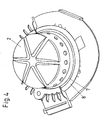
- it has an annular flange 7 on the an annular elastic assembly 8 (Fig. 4) or several segment-like elastic assemblies 9 (FIG. 3), e.g. made of silicone, are molded.
- segment-like elastic assemblies can instead of annular flange 7 also flange segments in the area the elastic assemblies can be arranged.
- the elastic assemblies have the cross-sectional shape of a lying Y, with an obliquely upward, i.e., obliquely in Direction of the cap 6 extending upper holding element 10 and with an incline downwards, i.e., at an angle into the above direction opposite direction lower holding element 11.
- the holding elements have a finger-shaped cross section.
- the diffuser housing 3 is attached to a generator support 12, from below a holding plate 13 is attached. All three parts 3, 12 and 13 are in one operation by bolts 14 and Nuts 15 connected together.
- the generator support 12 has a recess 16 into which the upper holding element 10 engages.
- the holding plate 13 has a recess 17 into which the lower holding element 11 engages.
- the gas generator 2 has an elastic assembly 18 on the shape of a hood has and slipped over the gas generator.
- the assembly 18 surrounds the gas generator at the bottom with a section 18a, so that it is securely connected to the gas generator.
- This Module 18 has at least one opening 19 for the outlet the gases after ignition of the gas generator 2.
- the assembly 18 has a holding element in the lower section 21, which runs obliquely downwards, a finger-like Has cross section and the gas generator 2 annular surrounds.
- the component 18 has a holding element in the upper section 20, which runs obliquely upwards, a finger-like Has cross section and the gas generator 2 also surrounds in a ring.
- 21 segment-like holding elements can also be provided be arranged at the same angular distance on the assembly 18 are. These are segment-like holding elements not shown separately, since the assembly 18 in the same in the case of the segments Has cross section, as shown in FIG. 5.
- the holding elements 20, 21 act with a holding plate 22 and a diffuser housing 23 which are connected by bolts 24 and nuts 25 are interconnected.
- the gas generator 2 provided with the assembly 18 put the holding plate 22 and then that Diffuser housing 23 placed.
- After connecting the Diffuser housing 23 with the holding plate 22 becomes the holding element 21 against this and against Recwnad 26 des Diffuser housing 23 pressed while the holding member 20th against the side wall 26 and the upper wall 27 of the diffuser housing 23 is pressed. This is the gas generator 2 securely elastic.
- any elastic Module 30 has an upper, obliquely upward aligned Holding element 31 and a lower one, oriented obliquely downwards Holding element 32 (Fig. 7).
- the holding elements 31, 32 engage in a recess 33 in a gas generator 2 attached holding part 34.
- the elastic assemblies also have a section 35 with which they between the generator support 28 and the holding plate 29 attached are.
Landscapes
- Engineering & Computer Science (AREA)
- Mechanical Engineering (AREA)
- Air Bags (AREA)
Abstract
Description
- Fig. 1
- einen Schnitt durch eine erste Ausführungsform eines Airbagmoduls für ein Lenkrad;
- Fig. 2
- die Einzelheit Z aus der Fig. 1;
- Fig. 3
- eine perspektivische Ansicht des Gasgenerators mit mehreren an dessen Umfang angebrachten Halteelementen;
- Fig. 4
- eine perspektivische Ansicht des Gasgenerators mit ringförmiger elastischer Baugruppe;
- Fig. 5
- einen Schnitt durch eine zweite Ausführungsform des Airbagmoduls mit unten und oben am Gasgenerator angebrachten Halteelementen;
- Fig. 6
- einen Schnitt durch eine dritte Ausführungsform des Airbagmoduls mit elastischen Halteelementen für den Gasgenerator, die an der Diffusorhalterung befestigt sind.
- Fig. 7
- die Einzelheit E aus der Fig. 6
Claims (18)
- Airbagmodul mit elastisch gelagertem Gasgenerator, mit Gassack und mit Abdeckung gegenüber dem Fahrgastraum, insbesondere für Lenkräder,
dadurch gekennzeichnet, daß der Gasgenerator (2) mittels mindestens einer elastischen Baugruppe (8, 9, 18, 30) gelagert ist, die mindestens ein Halteelement (10, 20, 31,) aufweist, das schräg nach oben, d.h., schräg in Richtung der Abdeckung (6) verläuft und mindestens ein Haltelement (11, 21, 32) aufweist, das schräg nach unten, d.h., schräg in die der vorgenannten Richtung entgegengesetzte Richtung verläuft, und daß beide Halteelemente (10, 11; 20, 21; 31, 32) am Gasgenerator (2) oder an einem dem Gasgenerator (2) zugeordneten Abschnitt des Airbagmoduls (28, 29) befestigt sind und an der jeweils anderen Baugruppe, d.h. am zugeordneten Abschnitt des Airbagmoduls (12, 13) bzw. am Gasgenerator (2), anliegen. - Airbagmodul nach Anspruch 1, dadurch gekennzeichnet, daß mehrere segmentartige elastische Baugruppen (9) vorgesehen sind.
- Airbagmodul nach Anspruch 1 oder 2, dadurch gekennzeichnet, daß mindestens drei elastische Baugruppen (9) vorgesehen sind.
- Airbagmodul nach mindestens einem der vorhergehenden Ansprüche, dadurch gekennzeichnet, daß die elastischen Baugruppen (9) im gleichen Winkelabstand zueinander angeordnet sind.
- Airbagmodul nach Anspruch 1, dadurch gekennzeichnet, daß eine ringförmige elastische Baugruppe (8) vorgesehen ist.
- Airbagmodul nach mindestens einem der vorhergehenden Ansprüche, dadurch gekennzeichnet, daß die Halteelemente (10, 11, 20, 21, 31, 32) einen fingerförmigen Querschnitt aufweisen.
- Airbagmodul nach mindestens einem der vorhergehenden Ansprüche, dadurch gekennzeichnet, daß die elastische Baugruppe (8, 9, 30) die Querschnittsform eines Y aufweist, wobei die schräg verlaufenden Zweige des Y die Halteelemente (10, 11, 31, 32) darstellen.
- Airbagmodul nach Anspruch 7, dadurch gekennzeichnet, daß die elastische Baugruppe (8, 9, 30) im unteren Teil des Gasgenerators (2) angeordnet ist, wobei der untere, üblicherweise senkrechte Abschnitt (35) des Y in der Ebene eines Generatorträgers (12, 28) oder parallel zu dieser Ebene verläuft, wobei ein schräger Abschnitt des Y das schräg nach oben verlaufende Halteelement (10, 31) ist und wobei der andere schräge Abschnitt des Y das schräg nach unten verlaufende Halteelement (11, 32) ist.
- Airbagmodul nach mindestens einem der vorhergehenden Ansprüche, dadurch gekennzeichnet, daß das schräg nach oben verlaufende Halteelement (10) in eine Vertiefung (16) des Generatorträgers (12) eingreift und das schräg nach unten verlaufende Halteelement (11) in eine Vertiefung (17) einer mit dem Generatorträger (12) verbundenen Halteplatte (13) eingreift.
- Airbagmodul nach mindestens einem der vorhergehenden Ansprüche, dadurch gekennzeichnet, daß die elastische Baugruppe (8, 9) an mindestens einem mit dem Gasgenerator (2) verbundenen Flansch (7) befestigt ist.
- Airbagmodul nach mindestens einem der vorhergehenden Ansprüche, dadurch gekennzeichnet, daß die elastische Baugruppe (8, 9, 18, 30) aus Kautschuk oder Silikon besteht.
- Airbagmodul nach mindestens einem der vorhergehenden Ansprüche, daß die elastische Baugruppe (8, 9) am Gasgenerator (2) und/oder an dem mit diesem verbundenen Flansch (7) angespritzt ist.
- Airbagmodul nach mindestens einem der Ansprüche 1 bis 8, dadurch gekennzeichnet, daß die elastische Baugruppe (30) mit dem Generatorträger (28) verbunden ist und daß die schräg verlaufenden Zweige (31, 32) des Y in mindestens eine Ausnehmung (33) am Gasgenerator (2) eingreifen.
- Airbagmodul nach mindestens einem der Ansprüche 1 bis 6 und 11, dadurch gekennzeichnet, daß mindestens ein Halteelement (20, 21) im oberen und unteren Bereich des Gasgenerators (2) vorgesehen ist.
- Airbagmodul nach mindestens einem der Ansprüche 1 bis 6 sowie 11 und 14, dadurch gekennzeichnet, daß die Halteelemente (20, 21) am Gasgenerator befestigt sind, daß das im oberen Bereich des Gasgenerators angeordnete Halteelement an einem den Gasgenerator (2) umgebenden Gehäuse (26, 27) anliegt und daß das im unteren Bereich des Gasgenerators angeordnete Halteelement (21) am Gehäuse (26) und an einer Halteplatte (22) anliegt.
- Airbagmodul nach mindestens einem der Ansprüche 1 bis 6, 11, 14 und 15, dadurch gekennzeichnet, daß als Gehäuse ein Diffusorgehäuse (23) vorgesehen ist.
- Airbagmodul nach mindestens einem der Ansprüche 1 bis 6, 11, 14, 15 und 16, dadurch gekennzeichnet, daß die elastische Baugruppe (18) über den Gasgenerator (2) stülpbar ist.
- Airbagmodul nach mindestens einem der vorhergehenden Ansprüche, dadurch gekennzeichnet, daß zwischen dem Gasgenerator (2) und einer mit dem Kraftfahrzeug verbundenen metallischen Baugruppe ein flexibles Erdungskabel angeordnet ist.
Applications Claiming Priority (2)
| Application Number | Priority Date | Filing Date | Title |
|---|---|---|---|
| DE10215330A DE10215330C1 (de) | 2002-04-03 | 2002-04-03 | Airbagmodul mit elastisch gelagertem Gasgenerator |
| DE10215330 | 2002-04-03 |
Publications (3)
| Publication Number | Publication Date |
|---|---|
| EP1350690A2 true EP1350690A2 (de) | 2003-10-08 |
| EP1350690A3 EP1350690A3 (de) | 2004-02-04 |
| EP1350690B1 EP1350690B1 (de) | 2011-09-14 |
Family
ID=7714303
Family Applications (1)
| Application Number | Title | Priority Date | Filing Date |
|---|---|---|---|
| EP03090065A Expired - Lifetime EP1350690B1 (de) | 2002-04-03 | 2003-03-14 | Airbagmodul mit elastisch gelagertem Gasgenerator |
Country Status (4)
| Country | Link |
|---|---|
| US (1) | US6962362B2 (de) |
| EP (1) | EP1350690B1 (de) |
| JP (1) | JP3770885B2 (de) |
| DE (1) | DE10215330C1 (de) |
Families Citing this family (13)
| Publication number | Priority date | Publication date | Assignee | Title |
|---|---|---|---|---|
| US20060061068A1 (en) * | 2004-09-20 | 2006-03-23 | Krista Nash | Dab vibration damper |
| US7144034B2 (en) * | 2004-02-18 | 2006-12-05 | Autoliv Asp, Inc. | Vibration damper gasket |
| EP1718503B1 (de) * | 2004-02-18 | 2009-12-16 | Autoliv Asp, Inc. | Schwingungsdämpferdichtung |
| DE102004010144B4 (de) * | 2004-02-27 | 2006-03-23 | Zf Friedrichshafen Ag | Anordnung zur Festlegung des Gasgenerators einer Airbageinheit |
| DE102006007085A1 (de) * | 2006-02-15 | 2007-08-23 | Woco Avs Gmbh | Anordnung zum Ableiten elektrostatischer Ladungen, Airbagmodul mit dieser Anordnung und Verfahren zum Montieren einer elektrisch leitfähigen, langgestreckten, starren Struktur in ein Schwingungstilgersystem |
| US7350800B2 (en) * | 2006-04-06 | 2008-04-01 | Arc Automotive, Inc. | Air bag inflator vibration damper |
| DE102007054054A1 (de) * | 2007-11-13 | 2009-05-20 | Woco Avs Gmbh | Airbag-System für ein Kraftfahrzeug mit einem Gasgenerator |
| DE102009030601B4 (de) | 2009-06-26 | 2025-08-07 | ZF Automotive Safety Germany GmbH | Gassackmodul für ein Fahrzeuginsassen-Rückhaltesystem |
| DE102012004866A1 (de) | 2012-03-13 | 2013-09-19 | Trw Automotive Safety Systems Gmbh | Airbagmodul für ein Kraftfarzeuglenkrad |
| JP2013203343A (ja) * | 2012-03-29 | 2013-10-07 | Toyoda Gosei Co Ltd | エアバッグ装置 |
| DE202014008432U1 (de) * | 2014-10-23 | 2016-01-26 | Trw Automotive Safety Systems Gmbh | Vorrichtung zur schwingfähigen Befestigung eines Gasgenerators in einem Airbagmodul |
| DE102017217344B4 (de) * | 2017-09-28 | 2023-12-07 | Joyson Safety Systems Germany Gmbh | Lenkrad für ein Kraftfahrzeug |
| KR20240111038A (ko) * | 2023-01-09 | 2024-07-16 | 현대모비스 주식회사 | 에어백용 리테이너 및 이를 포함하는 에어백용 리테이너 어셈블리 |
Citations (2)
| Publication number | Priority date | Publication date | Assignee | Title |
|---|---|---|---|---|
| EP1020332A2 (de) | 1998-12-18 | 2000-07-19 | Delphi Technologies, Inc. | Luftsackmodul für Kraftfahrzeuge |
| DE20108594U1 (de) | 2001-05-22 | 2001-09-27 | TRW Automotive Safety Systems GmbH & Co. KG, 63743 Aschaffenburg | Gassackmodul |
Family Cites Families (10)
| Publication number | Priority date | Publication date | Assignee | Title |
|---|---|---|---|---|
| DE4430588C2 (de) * | 1994-08-19 | 1999-02-25 | Petri Ag | Gassack (Airbag)-System für Kraftfahrzeuge |
| JPH09301117A (ja) | 1996-05-10 | 1997-11-25 | Nissan Motor Co Ltd | エアバッグ制御装置 |
| DE19645373A1 (de) | 1996-10-22 | 1998-04-30 | Petri Ag | Verfahren zur Sicherung eines Fahrzeuginsassen und Airbagmodul zur Durchführung des Verfahrens |
| DE29816923U1 (de) | 1998-09-16 | 1998-11-26 | Petri Ag, 63743 Aschaffenburg | Lenkrad mit Airbagmodul |
| DE29816925U1 (de) | 1998-09-16 | 1998-11-26 | Petri Ag, 63743 Aschaffenburg | Lenkrad mit Airbagmodul |
| DE19955426B4 (de) * | 1999-11-18 | 2005-11-10 | Carl Freudenberg Kg | Gasgenerator für einen Airbag |
| DE10110534A1 (de) | 2001-03-05 | 2002-09-26 | Freudenberg Carl Kg | Gasgenerator für einen Airbag am Lenkrad eines Kraftfahrzeuges |
| DE10110912B4 (de) * | 2001-03-07 | 2007-04-05 | Carl Freudenberg Kg | Airbagmodul für ein Lenkrad eines Kraftfahrzeugs |
| DE20105434U1 (de) * | 2001-03-28 | 2002-05-16 | TRW Automotive Safety Systems GmbH & Co. KG, 63743 Aschaffenburg | Gassackmodul |
| DE20105733U1 (de) * | 2001-04-02 | 2001-10-11 | TRW Automotive Safety Systems GmbH & Co. KG, 63743 Aschaffenburg | Schwingungsentkoppelt gelagerter Gasgenerator |
-
2002
- 2002-04-03 DE DE10215330A patent/DE10215330C1/de not_active Revoked
-
2003
- 2003-03-14 EP EP03090065A patent/EP1350690B1/de not_active Expired - Lifetime
- 2003-03-28 US US10/401,144 patent/US6962362B2/en not_active Expired - Fee Related
- 2003-04-02 JP JP2003132367A patent/JP3770885B2/ja not_active Expired - Fee Related
Patent Citations (2)
| Publication number | Priority date | Publication date | Assignee | Title |
|---|---|---|---|---|
| EP1020332A2 (de) | 1998-12-18 | 2000-07-19 | Delphi Technologies, Inc. | Luftsackmodul für Kraftfahrzeuge |
| DE20108594U1 (de) | 2001-05-22 | 2001-09-27 | TRW Automotive Safety Systems GmbH & Co. KG, 63743 Aschaffenburg | Gassackmodul |
Also Published As
| Publication number | Publication date |
|---|---|
| JP3770885B2 (ja) | 2006-04-26 |
| DE10215330C1 (de) | 2003-04-24 |
| US6962362B2 (en) | 2005-11-08 |
| US20030214119A1 (en) | 2003-11-20 |
| EP1350690B1 (de) | 2011-09-14 |
| JP2004034969A (ja) | 2004-02-05 |
| EP1350690A3 (de) | 2004-02-04 |
Similar Documents
| Publication | Publication Date | Title |
|---|---|---|
| DE69728193T2 (de) | Befestigungsstift für eine Schnappbefestigung | |
| EP1113948B2 (de) | Lenkrad mit airbagmodul | |
| EP1113950B1 (de) | Lenkrad mit airbagmodul | |
| EP0994793B1 (de) | Lenkrad mit airbagmodul | |
| DE69306338T2 (de) | Schwimmendes Luftsackmodul mit wartungsfähigem Hupenschalter | |
| DE10215330C1 (de) | Airbagmodul mit elastisch gelagertem Gasgenerator | |
| EP1048553B1 (de) | Fahrzeugdach mit eingesetzem Dachmodul und Montageverfahren dafür | |
| EP1912833B1 (de) | Befestigungsanordnung in einem airbagmodul | |
| EP3209525B1 (de) | Gassackmodul, diffusor für ein gassackmodul sowie fahrzeuginsassen-sicherungssystem | |
| EP0983914A2 (de) | Mittel zur Befestigung eines Gasgenerators in einem Airbagmodul | |
| DE19905025A1 (de) | Airbagmodul | |
| EP1251041A2 (de) | Gassackmodul mit Silikonelement zur Schwingungsentkopplung | |
| EP1362751A1 (de) | Airbagmodul mit elastischer Lagerung des Gasgenerators | |
| DE4415765C2 (de) | Lenkrad | |
| DE10013472C2 (de) | Gasgenerator für einen Airbag an einem Kraftfahrzeug-Lenkrad | |
| DE20210372U1 (de) | Airbagmodul mit elastischer Lagerung des Gasgenerators | |
| DE102023122421B3 (de) | Mantelrohrschaltermodul zur klemmenden Befestigung an einem Mantelrohr einer Lenkspindel eines Kraftfahrzeugs, zugehörige Anordnung und Verwendung | |
| EP1281876A1 (de) | Befestigungselement für eine Verkleidung | |
| EP1060957B1 (de) | Baueinheit für ein Gassack-Modul und Gassack-Modul | |
| EP1314620B2 (de) | Mittel zur Befestigung eines Airbagmoduls in einem Kraftfahrzeug | |
| DE20104044U1 (de) | Gassack-Modul | |
| WO2023148281A1 (de) | Batteriesystem für die energieversorgung einer antriebseinheit eines fahrrades, fahrrad und verfahren zur montage eines batteriesystems | |
| EP1119484B1 (de) | Lenkrad mit kontaktbrücke | |
| EP1393992B1 (de) | Airbag-Modul sowie Baugruppe aus einem Lenkrad und einem Airbag-Modul | |
| DE602004011103T2 (de) | Motorlagervorrichtung |
Legal Events
| Date | Code | Title | Description |
|---|---|---|---|
| PUAI | Public reference made under article 153(3) epc to a published international application that has entered the european phase |
Free format text: ORIGINAL CODE: 0009012 |
|
| AK | Designated contracting states |
Kind code of ref document: A2 Designated state(s): AT BE BG CH CY CZ DE DK EE ES FI FR GB GR HU IE IT LI LU MC NL PT RO SE SI SK TR |
|
| AX | Request for extension of the european patent |
Extension state: AL LT LV MK |
|
| PUAL | Search report despatched |
Free format text: ORIGINAL CODE: 0009013 |
|
| AK | Designated contracting states |
Kind code of ref document: A3 Designated state(s): AT BE BG CH CY CZ DE DK EE ES FI FR GB GR HU IE IT LI LU MC NL PT RO SE SI SK TR |
|
| AX | Request for extension of the european patent |
Extension state: AL LT LV MK |
|
| 17P | Request for examination filed |
Effective date: 20040518 |
|
| AKX | Designation fees paid |
Designated state(s): DE FR GB SE |
|
| 17Q | First examination report despatched |
Effective date: 20070827 |
|
| GRAP | Despatch of communication of intention to grant a patent |
Free format text: ORIGINAL CODE: EPIDOSNIGR1 |
|
| GRAS | Grant fee paid |
Free format text: ORIGINAL CODE: EPIDOSNIGR3 |
|
| GRAA | (expected) grant |
Free format text: ORIGINAL CODE: 0009210 |
|
| AK | Designated contracting states |
Kind code of ref document: B1 Designated state(s): DE FR GB SE |
|
| REG | Reference to a national code |
Ref country code: GB Ref legal event code: FG4D Free format text: NOT ENGLISH |
|
| REG | Reference to a national code |
Ref country code: DE Ref legal event code: R096 Ref document number: 50313948 Country of ref document: DE Effective date: 20111201 |
|
| PG25 | Lapsed in a contracting state [announced via postgrant information from national office to epo] |
Ref country code: SE Free format text: LAPSE BECAUSE OF FAILURE TO SUBMIT A TRANSLATION OF THE DESCRIPTION OR TO PAY THE FEE WITHIN THE PRESCRIBED TIME-LIMIT Effective date: 20110914 |
|
| RAP2 | Party data changed (patent owner data changed or rights of a patent transferred) |
Owner name: TAKATA AG |
|
| PLBE | No opposition filed within time limit |
Free format text: ORIGINAL CODE: 0009261 |
|
| STAA | Information on the status of an ep patent application or granted ep patent |
Free format text: STATUS: NO OPPOSITION FILED WITHIN TIME LIMIT |
|
| 26N | No opposition filed |
Effective date: 20120615 |
|
| REG | Reference to a national code |
Ref country code: DE Ref legal event code: R082 Ref document number: 50313948 Country of ref document: DE Representative=s name: MAIKOWSKI & NINNEMANN PATENTANWAELTE, DE |
|
| REG | Reference to a national code |
Ref country code: DE Ref legal event code: R097 Ref document number: 50313948 Country of ref document: DE Effective date: 20120615 |
|
| REG | Reference to a national code |
Ref country code: DE Ref legal event code: R081 Ref document number: 50313948 Country of ref document: DE Owner name: TAKATA AKTIENGESELLSCHAFT, DE Free format text: FORMER OWNER: TAKATA-PETRI AG, 63743 ASCHAFFENBURG, DE Effective date: 20120904 Ref country code: DE Ref legal event code: R082 Ref document number: 50313948 Country of ref document: DE Representative=s name: MAIKOWSKI & NINNEMANN PATENTANWAELTE, DE Effective date: 20120904 Ref country code: DE Ref legal event code: R081 Ref document number: 50313948 Country of ref document: DE Owner name: TAKATA AKTIENGESELLSCHAFT, DE Free format text: FORMER OWNER: TAKATA-PETRI AG, 63743 ASCHAFFENBURG, DE Effective date: 20111012 Ref country code: DE Ref legal event code: R082 Ref document number: 50313948 Country of ref document: DE Representative=s name: MAIKOWSKI & NINNEMANN PATENTANWAELTE PARTNERSC, DE Effective date: 20120904 |
|
| GBPC | Gb: european patent ceased through non-payment of renewal fee |
Effective date: 20120314 |
|
| PG25 | Lapsed in a contracting state [announced via postgrant information from national office to epo] |
Ref country code: GB Free format text: LAPSE BECAUSE OF NON-PAYMENT OF DUE FEES Effective date: 20120314 |
|
| PGFP | Annual fee paid to national office [announced via postgrant information from national office to epo] |
Ref country code: FR Payment date: 20140311 Year of fee payment: 12 |
|
| PGFP | Annual fee paid to national office [announced via postgrant information from national office to epo] |
Ref country code: DE Payment date: 20140417 Year of fee payment: 12 |
|
| REG | Reference to a national code |
Ref country code: DE Ref legal event code: R119 Ref document number: 50313948 Country of ref document: DE |
|
| REG | Reference to a national code |
Ref country code: FR Ref legal event code: ST Effective date: 20151130 |
|
| PG25 | Lapsed in a contracting state [announced via postgrant information from national office to epo] |
Ref country code: DE Free format text: LAPSE BECAUSE OF NON-PAYMENT OF DUE FEES Effective date: 20151001 |
|
| PG25 | Lapsed in a contracting state [announced via postgrant information from national office to epo] |
Ref country code: FR Free format text: LAPSE BECAUSE OF NON-PAYMENT OF DUE FEES Effective date: 20150331 |