EP1350665A2 - Control apparatus and method for at least one electrical rotating machine using compound current - Google Patents
Control apparatus and method for at least one electrical rotating machine using compound current Download PDFInfo
- Publication number
- EP1350665A2 EP1350665A2 EP03007360A EP03007360A EP1350665A2 EP 1350665 A2 EP1350665 A2 EP 1350665A2 EP 03007360 A EP03007360 A EP 03007360A EP 03007360 A EP03007360 A EP 03007360A EP 1350665 A2 EP1350665 A2 EP 1350665A2
- Authority
- EP
- European Patent Office
- Prior art keywords
- command value
- phase difference
- current
- rotors
- rotating machine
- Prior art date
- Legal status (The legal status is an assumption and is not a legal conclusion. Google has not performed a legal analysis and makes no representation as to the accuracy of the status listed.)
- Granted
Links
Images


Classifications
-
- B—PERFORMING OPERATIONS; TRANSPORTING
- B60—VEHICLES IN GENERAL
- B60L—PROPULSION OF ELECTRICALLY-PROPELLED VEHICLES; SUPPLYING ELECTRIC POWER FOR AUXILIARY EQUIPMENT OF ELECTRICALLY-PROPELLED VEHICLES; ELECTRODYNAMIC BRAKE SYSTEMS FOR VEHICLES IN GENERAL; MAGNETIC SUSPENSION OR LEVITATION FOR VEHICLES; MONITORING OPERATING VARIABLES OF ELECTRICALLY-PROPELLED VEHICLES; ELECTRIC SAFETY DEVICES FOR ELECTRICALLY-PROPELLED VEHICLES
- B60L15/00—Methods, circuits, or devices for controlling the traction-motor speed of electrically-propelled vehicles
- B60L15/02—Methods, circuits, or devices for controlling the traction-motor speed of electrically-propelled vehicles characterised by the form of the current used in the control circuit
- B60L15/025—Methods, circuits, or devices for controlling the traction-motor speed of electrically-propelled vehicles characterised by the form of the current used in the control circuit using field orientation; Vector control; Direct Torque Control [DTC]
-
- B—PERFORMING OPERATIONS; TRANSPORTING
- B60—VEHICLES IN GENERAL
- B60L—PROPULSION OF ELECTRICALLY-PROPELLED VEHICLES; SUPPLYING ELECTRIC POWER FOR AUXILIARY EQUIPMENT OF ELECTRICALLY-PROPELLED VEHICLES; ELECTRODYNAMIC BRAKE SYSTEMS FOR VEHICLES IN GENERAL; MAGNETIC SUSPENSION OR LEVITATION FOR VEHICLES; MONITORING OPERATING VARIABLES OF ELECTRICALLY-PROPELLED VEHICLES; ELECTRIC SAFETY DEVICES FOR ELECTRICALLY-PROPELLED VEHICLES
- B60L15/00—Methods, circuits, or devices for controlling the traction-motor speed of electrically-propelled vehicles
- B60L15/20—Methods, circuits, or devices for controlling the traction-motor speed of electrically-propelled vehicles for control of the vehicle or its driving motor to achieve a desired performance, e.g. speed, torque, programmed variation of speed
-
- B—PERFORMING OPERATIONS; TRANSPORTING
- B60—VEHICLES IN GENERAL
- B60L—PROPULSION OF ELECTRICALLY-PROPELLED VEHICLES; SUPPLYING ELECTRIC POWER FOR AUXILIARY EQUIPMENT OF ELECTRICALLY-PROPELLED VEHICLES; ELECTRODYNAMIC BRAKE SYSTEMS FOR VEHICLES IN GENERAL; MAGNETIC SUSPENSION OR LEVITATION FOR VEHICLES; MONITORING OPERATING VARIABLES OF ELECTRICALLY-PROPELLED VEHICLES; ELECTRIC SAFETY DEVICES FOR ELECTRICALLY-PROPELLED VEHICLES
- B60L50/00—Electric propulsion with power supplied within the vehicle
- B60L50/50—Electric propulsion with power supplied within the vehicle using propulsion power supplied by batteries or fuel cells
- B60L50/51—Electric propulsion with power supplied within the vehicle using propulsion power supplied by batteries or fuel cells characterised by AC-motors
-
- B—PERFORMING OPERATIONS; TRANSPORTING
- B60—VEHICLES IN GENERAL
- B60L—PROPULSION OF ELECTRICALLY-PROPELLED VEHICLES; SUPPLYING ELECTRIC POWER FOR AUXILIARY EQUIPMENT OF ELECTRICALLY-PROPELLED VEHICLES; ELECTRODYNAMIC BRAKE SYSTEMS FOR VEHICLES IN GENERAL; MAGNETIC SUSPENSION OR LEVITATION FOR VEHICLES; MONITORING OPERATING VARIABLES OF ELECTRICALLY-PROPELLED VEHICLES; ELECTRIC SAFETY DEVICES FOR ELECTRICALLY-PROPELLED VEHICLES
- B60L2220/00—Electrical machine types; Structures or applications thereof
- B60L2220/10—Electrical machine types
- B60L2220/14—Synchronous machines
-
- B—PERFORMING OPERATIONS; TRANSPORTING
- B60—VEHICLES IN GENERAL
- B60L—PROPULSION OF ELECTRICALLY-PROPELLED VEHICLES; SUPPLYING ELECTRIC POWER FOR AUXILIARY EQUIPMENT OF ELECTRICALLY-PROPELLED VEHICLES; ELECTRODYNAMIC BRAKE SYSTEMS FOR VEHICLES IN GENERAL; MAGNETIC SUSPENSION OR LEVITATION FOR VEHICLES; MONITORING OPERATING VARIABLES OF ELECTRICALLY-PROPELLED VEHICLES; ELECTRIC SAFETY DEVICES FOR ELECTRICALLY-PROPELLED VEHICLES
- B60L2240/00—Control parameters of input or output; Target parameters
- B60L2240/40—Drive Train control parameters
- B60L2240/42—Drive Train control parameters related to electric machines
- B60L2240/421—Speed
-
- B—PERFORMING OPERATIONS; TRANSPORTING
- B60—VEHICLES IN GENERAL
- B60L—PROPULSION OF ELECTRICALLY-PROPELLED VEHICLES; SUPPLYING ELECTRIC POWER FOR AUXILIARY EQUIPMENT OF ELECTRICALLY-PROPELLED VEHICLES; ELECTRODYNAMIC BRAKE SYSTEMS FOR VEHICLES IN GENERAL; MAGNETIC SUSPENSION OR LEVITATION FOR VEHICLES; MONITORING OPERATING VARIABLES OF ELECTRICALLY-PROPELLED VEHICLES; ELECTRIC SAFETY DEVICES FOR ELECTRICALLY-PROPELLED VEHICLES
- B60L2240/00—Control parameters of input or output; Target parameters
- B60L2240/40—Drive Train control parameters
- B60L2240/42—Drive Train control parameters related to electric machines
- B60L2240/423—Torque
-
- Y—GENERAL TAGGING OF NEW TECHNOLOGICAL DEVELOPMENTS; GENERAL TAGGING OF CROSS-SECTIONAL TECHNOLOGIES SPANNING OVER SEVERAL SECTIONS OF THE IPC; TECHNICAL SUBJECTS COVERED BY FORMER USPC CROSS-REFERENCE ART COLLECTIONS [XRACs] AND DIGESTS
- Y02—TECHNOLOGIES OR APPLICATIONS FOR MITIGATION OR ADAPTATION AGAINST CLIMATE CHANGE
- Y02T—CLIMATE CHANGE MITIGATION TECHNOLOGIES RELATED TO TRANSPORTATION
- Y02T10/00—Road transport of goods or passengers
- Y02T10/60—Other road transportation technologies with climate change mitigation effect
- Y02T10/64—Electric machine technologies in electromobility
-
- Y—GENERAL TAGGING OF NEW TECHNOLOGICAL DEVELOPMENTS; GENERAL TAGGING OF CROSS-SECTIONAL TECHNOLOGIES SPANNING OVER SEVERAL SECTIONS OF THE IPC; TECHNICAL SUBJECTS COVERED BY FORMER USPC CROSS-REFERENCE ART COLLECTIONS [XRACs] AND DIGESTS
- Y02—TECHNOLOGIES OR APPLICATIONS FOR MITIGATION OR ADAPTATION AGAINST CLIMATE CHANGE
- Y02T—CLIMATE CHANGE MITIGATION TECHNOLOGIES RELATED TO TRANSPORTATION
- Y02T10/00—Road transport of goods or passengers
- Y02T10/60—Other road transportation technologies with climate change mitigation effect
- Y02T10/70—Energy storage systems for electromobility, e.g. batteries
-
- Y—GENERAL TAGGING OF NEW TECHNOLOGICAL DEVELOPMENTS; GENERAL TAGGING OF CROSS-SECTIONAL TECHNOLOGIES SPANNING OVER SEVERAL SECTIONS OF THE IPC; TECHNICAL SUBJECTS COVERED BY FORMER USPC CROSS-REFERENCE ART COLLECTIONS [XRACs] AND DIGESTS
- Y02—TECHNOLOGIES OR APPLICATIONS FOR MITIGATION OR ADAPTATION AGAINST CLIMATE CHANGE
- Y02T—CLIMATE CHANGE MITIGATION TECHNOLOGIES RELATED TO TRANSPORTATION
- Y02T10/00—Road transport of goods or passengers
- Y02T10/60—Other road transportation technologies with climate change mitigation effect
- Y02T10/72—Electric energy management in electromobility
Definitions
- the present invention relates generally to control apparatus and method for at least one electrical rotating machine using a compound current.
- the present invention more particularly, relates to control apparatus and method for an electrical rotating machine having two rotors disposed in the electrical rotating machine on the same axis of rotation and driven independently of each other by means of a compound current and commonly associated with a single stator or a pair of electrical rotating machines, each electrical rotating machine being provided with one of the two rotors, each rotor being independently driven by means of the compound current.
- a current (component) for the first rotor has an amplitude of 100 A (Amperes) and another current (component) for the second rotor has an amplitude of 50 A
- these two currents are simply added to achieve the compound current having a maximum amplitude of 150 A.
- the maximum amplitude value of the compound current is varied in accordance with the phase difference between each current to be caused to flow into the stator coil for each rotor.
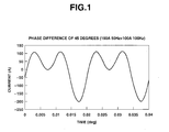
- Fig. 1 shows a graph representing a compound current waveform in a case where the phase difference between each original current is 45 degrees.
- the compound current shown in Fig. 1 is a sum of a first current (AC) for the first rotor having an amplitude of 100A and a frequency of 50Hz and a second current (AC) for the second rotor having an amplitude of 100A and a frequency of 100Hz.
- Fig. 2 shows a graph representing the compound current waveform in a case where the phase difference between each original current is 90 degrees.
- the compound current is the sum of the first current having the amplitude of 100A and the frequency of 50Hz and the second current having the amplitude of 100A and the frequency of 100Hz.
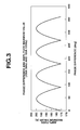
- Fig. 1 shows a graph representing a compound current amplitude maximum value phase-difference dependent characteristic. It is noted that the compound current shown in each of Figs. 1 and 2 was used and only the phase difference was varied to obtain the amplitude maximum value. It will be appreciated from Fig.
- the current maximum value is varied from 200 A (the phase difference is approximately 45 degrees) to about 175A (phase difference is approximately 90 degrees). That is to say, it is possible to suppress the maximum current value to be lower by controlling the phase difference between each original current utilizing this phenomenon while exhibiting the same motor outputs. Under this condition, it will be appreciated from Fig. 3 that, if the phase difference is controlled to be a multiple of 90 degrees, the maximum current value can be suppressed to be minimized.
- the term of low is derived from a height of the current waveform and has the same meaning as small from a viewpoint of a current value.
- an object of the present invention to provide control apparatus and method for at least one electrical rotating machine which control the phase difference between each original current constituting the compound current for the corresponding one of the rotors of the electrical rotating machine so as to suppress the maximum value of the compound current to a lower (or smaller) value (preferably, equal to or lower than an average value of the current values when the phase difference is varied and, more preferably, to a minimum value), thus achieving an effective use of a device (the electrical rotating machine or the pair of electrical rotating machines) into which the compound current is caused to flow and achieving a reduction of the compound current.
- a control apparatus for at least one electrical rotating machine comprising: two rotors disposed in the electrical rotating machine on the same axis of rotation and being driven independently of each other by means of a generated compound current and commonly associated with at least one stator; and a controlling section that controls a position of at least one of the rotors in such a manner that a maximum value of the compound current is suppressed to be reduced as low as possible.
- a control method for at least one electrical rotating machine comprising: two rotors disposed in the electrical rotating machine on the same axis of rotation; and at least one stator commonly associated with the respective rotors, the control method comprising: generating a compound current by means of which the respective rotors are driven independently of each other; and controlling a position of at least one of the rotors in such a manner that a maximum value of the compound current is suppressed to be reduced as low as possible.
- Fig. 1 is a characteristic graph representing a compound current waveform when a phase difference between compound current components for respective two rotors of at least one electrical rotating machine is 45 degrees.
- Fig. 2 is a characteristic graph representing a compound current waveform when a phase difference between compound current components for respective two rotors of at least one electrical rotating machine is 90 degrees.
- Fig. 3 is a graph representing a phase difference dependent characteristic of a current maximum value.
- Fig. 4 is a cross sectional view of an electrical rotating machine to which a control apparatus according to the present invention is applicable.
- Fig. 5 is another cross sectional view of the electrical rotating machine to which a control apparatus according to the present invention is applicable.
- Fig. 6 is a cross sectional view of a pair of electrical rotating machines to which the control apparatus according to the present invention is applicable.
- Fig. 7 is a functional block diagram of a basic structure of the control apparatus for at least one rotating machine according to the present invention.
- Fig. 8 is a functional block diagram of a phase difference generator shown in Fig. 7.
- Figs. 9A and 9B are map views for explaining a predetermined three-dimensional map used for detecting a phase difference and for explaining another predetermined two-dimensional map used for deriving d-axis and q-axis currents, respectively.
- Fig. 10 is a detailed functional block diagram of a torque command value generator 130 shown in Fig. 7.
- Fig. 11 is a functional block diagram of a variation of torque command generator 130 shown in Fig. 10.
- Figs. 12A and 12B are model views of encoder signals for explaining a principle of operation of a phase difference detector 120 shown in Fig. 7.
- Fig. 13 is an operational flowchart for explaining an example of an operation of a controlling section of the control apparatus according to the present invention.
- Figs. 14A, 14B, and 14C are examples of the electrical rotating machine constituting a single compound motor to which the control apparatus according to the present invention is applicable and the pair of electrical rotating machines constituting two compound motors to which the control apparatus according to the present invention is applicable.
- Fig. 4 shows a cross sectional view of an electrical rotating machine main body 1 which is an object to be controlled of the control apparatus according to the present invention. It is noted that Figs. 1, 2, and 3 have already been explained in the SUMMARY OF THE INVENTION.
- a hollow cylindrical stator 2 has an inner circumferential wall and an outer circumferential wall.
- An inner rotor 3 is arranged around the inner circumferential side of stator 2 with a predetermined gap therebetween.
- An outer rotor 4 is arranged around the outer periphery of stator 2 with a predetermined gap therebetween. (This is, often, called a three-layer structure).
- Inner and outer rotors 3 and 4 are disposed on the same axis of rotation so as to enable a rotation of an outer frame (not shown in Fig. 4).
- inner and outer rotors 3, 4 are located at an inside of stator 2 and an outside thereof, it is necessary to arrange coils 5 along stator 2 in order to cause a current generating a rotating (magnetic) field to flow into coils 5 for each of inner and outer rotors 3, 4.
- An arrangement of twelve coils 5 shown in Fig. 4 is obtained as a result of consideration by referring to Fig. 5.
- rotating machine 1 shown in Fig. 5 will, at first, will be explained.
- a total number (twelve) of the outer circumferential side coils 5b of stator 2 is twice the total number (six) of the inner circumferential side coils 5a.
- Three couples of induction coils 6 and 7 are arranged on respective inner and outer rotors 3, 4 so as to oppose against each of inner and outer circumferential side coils 5a and 5b of stator 2.
- an outer circumferential side of inner rotor 3 is provided with the same number of induction coils (six) as the inner circumferential side coils 5a of stator 2 (u phase, v phase, and w phase coils) at equal intervals to one another and an inner circumferential side of outer rotor 4 is provided with the same number (twelve) coils of induction coils (a phase, b phase, and c phase coils) as the outer circumferential side coil 5b are arranged at equal intervals to one another along the inner circumferential side of outer rotor 4 .
- the current flowing through inner circumferential side coil 5a provides the rotating field (an inner rotating magnetic field) for induction coils 6 of inner rotor 3 and the current flowing through outer circumferential side coil 5b provides the rotating field (an outer rotating magnetic field) for induction coils 7 of outer rotor 4.
- a number of a pair of poles of inner rotor 3 is 1
- a number of a pair of poles of outer rotor 4 is 2 so that an induction motor having a ratio of the number of pair of poles of two rotors 2 : 1 is structured.
- the control apparatus according to the present invention is applicable to a sinusoidal wave driven motor, for example, a synchronous motor, an induction synchronous motor, and a permanent magnet synchronous motor.
- a portion of the stator coil 5 in Fig. 4 to which numerals 1 and 2 are assigned corresponds to A phase coil A and C phase coil C from among the outer circumferential coils 5b in Fig. 5 and U phase coil U from among the inner circumferential coils 5a in Fig. 5.
- this slightly deviated phase coil is a new U' phase coil.
- a half of the current flowing through new U' phase coil is assigned to A phase coil A and C phase coil C in Fig. 5.
- the remaining portions of stator coil 5 shown in Fig. 4 are the similarly considered.
- current Ii through Ixii on each second term of a right side of equation (3) defines a twelve-phase current.
- This twelve-phase current can form the inner rotating field.
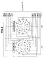
- Fig. 6 shows a cross sectional view of an example of a pair of ordinary rotating machine main bodies (stator coil connection) 40A and 41A which are an object to be controlled by the control apparatus according to the present invention.
- electrical rotating machine main bodies (stators) 40A and 41A equipped together with the respective rotors can be controlled individually and separately by means of the compound current supplied from inverter 160.
- a principle of operation on a control method of the pair of ordinary electrical rotating machines is the same as the single electrical rotating machine 1 described above.
- reference numerals 40A and 41A denotes right stator and left stator as will be described later with reference to Figs. 14B and 14C and left stator 41A constitutes 8-pole motor (in a case of Fig.
- Fig. 7 shows a functional block diagram of a basic structure of the control apparatus for at least one electrical rotating machine according to the present invention.
- a controlling section 100 in a preferred embodiment according to the present invention includes: a phase difference generator 110; a phase difference detector 120; a torque command value generator 130; and a vector controller 140.
- Phase difference generator 110 outputs a phase difference command value ⁇ *.
- Phase difference detector 120 outputs an actual phase difference ⁇ on the basis of phases detected from each position sensor constituted by, for example, a pulse encoder installed on the respective two rotors.
- Torque command value generator 130 receives a subtraction result of actual phase difference from the phase difference command value ⁇ * ( ⁇ * - ⁇ ) and outputs a torque command value T 1 * for one rotor on the basis of the subtraction result ( ⁇ * - ⁇ ).
- Vector controller 140 outputs a vector ⁇ 1 * (a voltage command value) for the one rotor (for example, rotor 1) on the basis of torque command value T 1 *. It is noted that an output vector ⁇ 2 * for the other rotor (rotor 2) from another vector controller 141 is added to vector ⁇ 1 * and the added result, viz., ( ⁇ 1 * + ⁇ 2 *) is applied to a PWM (Pulse Width Modulation) generator 150.
- PWM Pulse Width Modulation
- PWM generator 150 outputs a PWM waveform (so called, drive pulse) to be supplied to each coil of stator 2 via an inverter 160 so that one rotor (1 or 2) is acted upon independently and separately by means of the compound current generated at inverter 160 from the other rotor to revolve the one rotor.
- T 2 * another torque command value denoted by T 2 * is a torque value that a system demands and directly inputted to vector controller 141 since T 2 * is a torque command to one (rotor 2) of the rotors which is the object to be a torque controlled. It is also noted that, in Fig.
- i 1 denotes a current component (or original current) for one rotor (rotor 1) and i 2 denotes a current component (or original current) for the other rotor (rotor 2) and i 1 + i 2 denotes the compound current described above.
- Fig. 8 shows a functional block diagram of phase difference generator 110 shown in Fig. 7.
- Phase difference generator 110 calculates phase difference command value ⁇ * from four outputs of amplitudes I 1 p* of the current command value for one rotor (rotor 1) and I 2 p* thereof for the other rotor (rotor 2) and frequencies w 1 and w 2 of the current command value for one rotor (rotor 1) and the other rotor (rotor 2) in an on-line mode (a real time basis).
- phase difference command value ⁇ * in the on-line mode An example of calculating phase difference command value ⁇ * in the on-line mode will be described below.
- electrical angle one periods T 1 and T 2 for one rotor 1 and for the other rotor 2 are calculated by phase difference generator 110 from respective frequencies w 1 and w 2 in the current command values described above.
- a least common multiple Ts of the one periods T 1 and T 2 is calculated by phase difference generator 110.
- the following calculation is carried out by phase difference generator 110 using a pseudo time t up to a time corresponding to calculated least common multiple Ts.
- Fig. 9A shows a predetermined three-dimensional map for detecting the phase difference.
- phase difference generator 110 may, alternatively, refer to this map of Fig. 9A to output a previously calculated phase difference command value ⁇ *.
- controlling section 100 does not carry out the control of the position of the one rotor (rotor 1 or rotor 2) if the value of the amplitude of the current command value for the one rotor divided by the amplitude of the current command value for the other rotor is larger than a predetermined maximum threshold value or if the value of the amplitude of the current command value for the one rotor divided by the amplitude of the current command value for the other rotor is smaller than a predetermined minimum threshold value.
- Fig. 10 shows a detailed functional block diagram of torque command value generator 130 in more details shown in Fig. 7.
- the difference between phase difference command value ⁇ * and actual phase difference ⁇ is provided by means of a proportional controller 132 having a transfer function Kp.
- An output of proportional controller 132 is added to a desired speed command value w 1 * to provide a new speed command value w 1 *'.
- a deviation between the new speed command value w 1 *' and actual speed w 1 (w* 1 ' - w 1 ) is determined.
- a speed controller proportional integrator 134 having transfer functions of a proportional element K'pw and an integration element of Kpw/s (1/s denotes an integration operator) to provide torque command value T 1 *.
- the speed command value for one of the two rotors is increased (or decreased) until the actual phase difference reaches to an optimum phase difference (namely, the phase difference at which a level of the maximum value of the compound current becomes minimum). Then, as the actual phase difference ⁇ approaches to an optimum phase difference (suppressed to be lowest), the speed command value is gradually returned to an original value.
- proportional controller 122 may be omitted and torque command generator 130 may be constituted only by speed controller 134.
- Fig. 11 shows a functional block diagram representing a variation of torque command value generator 130 shown in Fig. 10.
- a position command value ( ⁇ 1 *) having no phase information is derived from speed command value w 1 * by integrator 1/s.
- Phase command value ⁇ * is derived on the basis of outputs of phase difference detector 120 and phase difference generator 110 described above.
- Position command value ⁇ 1 * is added to phase command value ⁇ * to provide a new phase command value ⁇ 1 *'.
- New phase command value ⁇ 1 *' is subtracted from actual phase ⁇ 1 , viz., the deviation of ( ⁇ 1 *' - ⁇ 1 ) is supplied to speed controller 138.
- Position controller 136 and speed controller 138 are connected in series with each other to constitute a robust control system. Hence, a second-order control system having a high robustness (robust against an external disturbance) can be constructed.
- Figs. 12A and 12B show model views for explaining a principle of operation of phase difference detector 120.
- Fig. 13 shows an example of an operational flowchart executed by controlling section 100 shown in Fig. 7 for at least one electrical rotating machine according to the present invention.
- controlling section 100 detects positions of each rotor 1 and 2 through the encoders 90D, 100D as described with reference to Figs. 12A and 12B to detect phase difference ⁇ between phases of the original currents constituting the compound current for the respective rotors on the basis of the detected rotor rotational positions.
- controlling section 100 generates phase difference command value ⁇ * which minimizes the compound current amplitude on the basis of the current command values one sampling time before the present sampling time for the respective rotors (rotor 1 and rotor 2).
- controlling section 100 compares generated phase difference command value ⁇ * and detected phase difference ⁇ to generate the deviation of ( ⁇ * - ⁇ ).
- torque command generator 130 of controlling section 100 receives the deviation and outputs torque command value T 1 *.
- controlling section 100 varies the position of the one of the rotors which is under the speed control from among the torque controlled rotor and the speed controlled rotor.
- controlling section 100 detects the phases of the respective rotors rotor 1 and rotor 2 in the same way as step S1.
- controlling section 100 compares phase difference command value ⁇ * with actual phase difference ⁇ to determine whether there is the deviation.
- rotors have induction coils, permanent magnets or electromagnets may be installed on the respective rotors of the rotating machine.
- rotors and stator may be modified.
- the present invention is applicable to such a rotating machine or rotating machines that the plurality of rotors are driven by means of the compound current.
- Figs. 14A is an example of the rotating machine having two rotors of inner rotor and outer rotor. In Fig.
- FIG. 14A shows an example of the pair of electrical machines.
- An integrated rotating machine (a compound motor) 110A shown in Fig. 14B includes: a left compound motor 100B having a left stator 41A, a left rotor 43A, and a coaxial axle 45A, a right compound motor 100A having right stator 40A, a right rotor 42A, and a large diameter coaxial axle 44A.
- Fig. 14C shows an example of the pair of electrical rotating machine.
- a left rotating machine 110 includes left stator 41A, left rotor 43A, and a left axle 45A.
- a right rotating machine 110 includes right stator 40A, right rotor 42A, and a right axle 44A.
- Left axle 45A is on the same rotational axis as right axle 44A.
- the details of the rotating machines shown in Figs. 14A through 14C are described in a United States Patent Application Publication No. US2001/0020805 published on September 13, 2001 (the disclosure of which is herein incorporated by reference). It is noted that rotor 1 shown in Fig. 7 may correspond to inner rotor 3 (400) or right rotor 42A and rotor 2 may correspond to outer rotor 4 (300) or left rotor 43A or vice versa.
Landscapes
- Engineering & Computer Science (AREA)
- Power Engineering (AREA)
- Transportation (AREA)
- Mechanical Engineering (AREA)
- Life Sciences & Earth Sciences (AREA)
- Sustainable Development (AREA)
- Sustainable Energy (AREA)
- Control Of Ac Motors In General (AREA)
- Control Of Multiple Motors (AREA)
- Connection Of Motors, Electrical Generators, Mechanical Devices, And The Like (AREA)
Abstract
Description
Claims (19)
- A control apparatus for at least one electrical rotating machine, comprising:two rotors (3, 4, 300, 400, 42A, 43A) disposed in the electrical rotating machine on the same axis of rotation and being driven independently of each other by means of a generated compound current and associated with at least one stator(2, 200, 40A, 41A); anda controlling section (100) that controls a position of at least one of the rotors in such a manner that a maximum value of the compound current is reduced as low as possible.
- A control apparatus for at least one electrical rotating machine as claimed in claim 1, wherein the electrical rotating machine comprises a pair of electrical rotating machines, each electrical rotating machine being provided with a corresponding one of the two rotors, each rotor being independently driven by means of the compound current.
- A control apparatus for at least one electrical rotating machine as claimed in either claim 1 or claim 2, wherein the controlling section variably controls the position of at least one of the rotors in such a manner that the maximum value of the compound current is reduced to a minimum value when varying the position of at least one of the rotors.
- A control apparatus for at least one electrical rotating machine as claimed in any one of the preceding claims 1 through 3, wherein the controlling section (100) comprises: a phase difference generator (110) that calculates a phase difference command value Δϕ* between phases of original currents of the compound current for the respective rotors to reduce the maximum value of the compound current as low as possible; a phase difference detector (120) that detects a phase difference Δϕ between the phases of the original currents for the respective rotors; a torque command value generator (130) that generates a torque command value T1* for one of the rotors on the basis of the phase difference command value Δϕ* and the detected phase difference Δϕ; and a vector controller (140) that generates and outputs each current command value to be supplied to the stator for a corresponding one of the rotors on the basis of the generated torque command value T1*.
- A control apparatus for at least one electrical rotating machine as claimed in any one of the preceding claims 1 through 4, wherein the compound current is generated from the current command values for the rotors in such a manner as to be caused to flow through the stator for the respective rotors, each current command value including an amplitude I1p*, I2p* and a frequency w1, w2, and the phase difference generator calculates the phase difference command value Δϕ* on a real time basis on the basis of respective amplitudes and frequencies included in the respective current command values.
- A control apparatus for at least one electrical rotating machine as claimed in any one of the preceding claims 1 through 4, wherein the compound current is generated from the current command values in such a manner as to be caused to flow through the stator for the respective rotors, each current command value including an amplitude I1p*, I2p*, and a frequency w1, w2, and the phase difference generator calculates the phase difference command value Δϕ* by referring to a predetermined map on the basis of the amplitudes and frequencies of the current command values.
- A control apparatus for at least one electrical rotating machine as claimed in any one of the preceding claims 1 through 4, wherein current command values generated by the vector controller are held for a constant interval of time and the phase difference generator calculates the phase difference command value Δϕ* on the basis of the respective amplitudes I1p*, I2p* and frequencies w1, w2 included in the respective current command values.
- A control apparatus for at least one electrical rotating machine as claimed in claim 6, wherein the predetermined map is a three-dimensional map having three axes constituting a value (I1p*/I2p*) of the amplitude of the current command value for one rotor divided by the amplitude of the current command value for the other rotor and the respective frequencies (w1, w2) of the current command values for the respective rotors.
- A control apparatus for at least one electrical rotating machine as claimed in claim 8, wherein the controlling section halts the control of the position of the one rotor if the value of the amplitude of the current command value for the one rotor divided by the amplitude of the current command value for the other rotor is larger than a predetermined maximum threshold value or if the value of the amplitude of the current command value for the one rotor divided by the amplitude of the current command value for the other rotor is smaller than a predetermined minimum threshold value.
- A control apparatus for at least one electrical rotating machine as claimed in any one of the preceding claims 1 through 5, wherein the phase difference generator calculates each electrical angle period (T1, T2) of the current command values on the basis of the respective frequencies (w1, w2) included in each current command value for the respective rotors, an internal time loop is constructed in such a manner that a unit time width of a pseudo time t is proportional to a least common multiple period Ts, calculates the maximum value of the compound current while varying the phase of the current command value for one of the respective rotors, and calculates the phase difference command value Δϕ* in such the manner that the calculated maximum value of the compound current becomes reduced.
- A control apparatus for at least one electrical rotating machine as claimed in any one of the preceding claims 1 through 4, wherein the phase difference detector detects the phase difference Δϕ between the phases of the original currents constituting the compound current for the respective rotors using an output signal from a position sensor disposed on each rotor on the basis of a falling edge of the output signal outputted at the next time to the output signal from one of the position sensors of the two rotors whose electrical angle frequency is lower than that from the other position sensor from among the falling edges of the output signals outputted for each electrical angle period from the respective position sensors.
- A control apparatus for at least one electrical rotating machine as claimed in any one of the preceding claims 1 through 4, wherein the torque command value generator generates the torque command value T1* by deriving a difference between the phase difference command value Δϕ* outputted from the phase difference generator and the phase difference Δϕ detected by the phase difference detector, by inputting the difference into a phase controller (132) constituted by a proportional controller, an output of the phase controller being added to a speed command value w1* to provide a speed command value w1* in a case where an object to be controlled is speed controlled rotor, and by inputting a difference between the speed command value and the frequency (w1) of the current command value to a speed controller (134).
- A control apparatus for at least one electrical rotating machine as claimed in any one of the preceding claims 1 through 4, wherein the torque command value generator generates the torque command value T1* by outputting a phase command value (δ*) of an object to be phase controlled on the basis of the phase difference command value outputted from the phase difference generator and the phase difference outputted from the phase difference detector, by inputting a position command value (1*) calculated from a special speed command value (W1*) added to the phase command value to provide a new position command value (1*') to a position controller, and by inputting the new position command value outputted from the position controller into a speed controller.
- A control apparatus for at least one electrical rotating machine as claimed in any one of the preceding claims 1 through 4, wherein, in a case where one of the two rotors is a speed controlled rotor and the other rotor is a torque controlled rotor, the controlling section executes a position varying step at which the position of the speed controlled rotor is varied on the basis of the torque command value, detects the phase difference between the phases of the original currents for the speed controlled rotor and the torque controlled rotor, executes a deviation generation step at which the detected phase difference is compared with the phase difference command value to generate a deviation therebetween, generates a new torque command value with the deviation therebetween fedback to the torque command generator to generate a new torque command value, executes the position varying step and the deviation generation step, and repeats the generation and execution until the deviation therebetween becomes zero.
- A control method for at least one electrical rotating machine, the electrical rotating machine comprising: two rotors (3, 4, 300, 400, 42A, 43A) disposed in the electrical rotating machine on the same axis of rotation; and at least one stator (2, 200, 40A, 41A) associated with the respective rotors, the control method comprising:generating a compound current by means of which the respective rotors are driven independently of each other; andcontrolling a position of at least one of the rotors in such a manner that a maximum value of the compound current is reduced as low as possible.
- A control method for at least one electrical rotating machine as claimed in claim 15, wherein the electrical rotating machine comprises a pair of electrical rotating machines, each electrical rotating machine being provided with a corresponding one of the two rotors, each rotor being independently driven by means of the compound current.
- A control method for at least one electrical rotating machine as claimed in either claim 15 or claim 16, wherein controlling the position of at least one of the rotors comprises: calculating a phase difference command value Δψ* between phases of original currents of the compound current for the respective rotors to reduce the maximum value of the compound current as low as possible; detecting a phase difference Δϕ between the phases of the original currents of the compound current for the respective rotors; generating a torque command value T1* on the basis of the phase difference command value Δϕ* and the detected phase difference Δϕ; and generating and outputting each current command value to be supplied to the stator for a corresponding one of the rotors on the basis of the generated torque command value T1*.
- A control method for at least one electrical rotating machine as claimed in claim any one of the preceding claims 15 through 16, wherein the compound current is generated from the respective current command values in such a manner as to be caused to flow through the stator for each of the rotors, each current command value including an amplitude I1p*, I2p* and a frequency w1, w2, and the phase difference command value Δϕ* is calculated on a real time basis on the basis of respective amplitudes and frequencies included in the respective current command values.
- A control method for at least one electrical rotating machine as claimed in either claim 15 or claim 16, wherein the compound current is generated from the current command values to be caused to flow through the stator for the respective rotors, each current command value including an amplitude I1p*, I2p*, and a frequency w1, w2, and the phase difference command value Δϕ* is calculated by referring to a predetermined map on the basis of the amplitudes and frequencies of the current command values.
Applications Claiming Priority (2)
| Application Number | Priority Date | Filing Date | Title |
|---|---|---|---|
| JP2002098149A JP3711955B2 (en) | 2002-04-01 | 2002-04-01 | Control device for rotating electrical machine |
| JP2002098149 | 2002-04-01 |
Publications (3)
| Publication Number | Publication Date |
|---|---|
| EP1350665A2 true EP1350665A2 (en) | 2003-10-08 |
| EP1350665A3 EP1350665A3 (en) | 2004-06-30 |
| EP1350665B1 EP1350665B1 (en) | 2018-05-23 |
Family
ID=28035879
Family Applications (1)
| Application Number | Title | Priority Date | Filing Date |
|---|---|---|---|
| EP03007360.5A Expired - Lifetime EP1350665B1 (en) | 2002-04-01 | 2003-04-01 | Control apparatus and method for at least one electrical rotating machine using compound current |
Country Status (3)
| Country | Link |
|---|---|
| US (1) | US6879125B2 (en) |
| EP (1) | EP1350665B1 (en) |
| JP (1) | JP3711955B2 (en) |
Cited By (4)
| Publication number | Priority date | Publication date | Assignee | Title |
|---|---|---|---|---|
| EP1858140A1 (en) * | 2006-05-19 | 2007-11-21 | Pratt & Whitney Canada Corp. | Fault monitoring of electric machines |
| US7583048B2 (en) | 2006-03-22 | 2009-09-01 | Honda Motor Co., Ltd. | Controller for motor |
| US7830106B2 (en) | 2006-08-04 | 2010-11-09 | Honda Motor Co., Ltd | Controller for motor |
| US11387724B2 (en) | 2019-01-14 | 2022-07-12 | Rolls-Royce Plc | Dual-rotor electric machine |
Families Citing this family (18)
| Publication number | Priority date | Publication date | Assignee | Title |
|---|---|---|---|---|
| JP3711956B2 (en) * | 2002-04-01 | 2005-11-02 | 日産自動車株式会社 | Driving method of rotating electric machine |
| CN101091119B (en) * | 2005-04-01 | 2010-08-18 | 三菱电机株式会社 | tram control device |
| JP4712585B2 (en) * | 2006-03-22 | 2011-06-29 | 本田技研工業株式会社 | Electric motor control device |
| JP4754379B2 (en) * | 2006-03-22 | 2011-08-24 | 本田技研工業株式会社 | Electric motor control device |
| JP4879649B2 (en) * | 2006-03-22 | 2012-02-22 | 本田技研工業株式会社 | Electric motor control device |
| JP2008043135A (en) * | 2006-08-09 | 2008-02-21 | Honda Motor Co Ltd | Control device for vehicle motor |
| JP4163226B2 (en) * | 2006-08-31 | 2008-10-08 | 本田技研工業株式会社 | Motor control device |
| US7750521B2 (en) * | 2006-12-07 | 2010-07-06 | General Electric Company | Double-sided starter/generator for aircrafts |
| JP5298476B2 (en) * | 2007-07-31 | 2013-09-25 | 日産自動車株式会社 | Induction synchronous motor |
| JP5362840B2 (en) | 2009-10-13 | 2013-12-11 | 本田技研工業株式会社 | Hybrid vehicle |
| CN102548819A (en) | 2009-10-13 | 2012-07-04 | 本田技研工业株式会社 | Hybrid vehicle |
| WO2011045965A1 (en) * | 2009-10-13 | 2011-04-21 | 本田技研工業株式会社 | Hybrid vehicle |
| GB2489761B (en) * | 2011-09-07 | 2015-03-04 | Europlasma Nv | Surface coatings |
| KR101345326B1 (en) * | 2011-12-26 | 2013-12-30 | 주식회사 아모텍 | Motor drive circuit for washing machine and control method thereof |
| KR101994382B1 (en) * | 2012-11-09 | 2019-06-28 | 휴렛-팩커드 디벨롭먼트 컴퍼니, 엘.피. | Motor control apparatus, image forming apparatus having the same and motor control method |
| US9680348B2 (en) * | 2013-10-22 | 2017-06-13 | Ultra Motion LLC | Actuator position sensing |
| DE102017216707A1 (en) * | 2017-09-21 | 2019-03-21 | Robert Bosch Gmbh | Method and device for operating an electrically commutated machine |
| JP7188214B2 (en) * | 2019-03-25 | 2022-12-13 | コニカミノルタ株式会社 | Twin drive and motor control method |
Family Cites Families (20)
| Publication number | Priority date | Publication date | Assignee | Title |
|---|---|---|---|---|
| US20805A (en) * | 1858-07-06 | Improvement in raking and binding attachments to | ||
| JPS6318990A (en) | 1986-07-10 | 1988-01-26 | Mitsubishi Electric Corp | Controller for cycloconverter |
| JP3480300B2 (en) * | 1998-03-25 | 2003-12-15 | 日産自動車株式会社 | Rotating electric machine |
| JP3480302B2 (en) * | 1998-03-25 | 2003-12-15 | 日産自動車株式会社 | Rotating electric machine |
| JP3480301B2 (en) * | 1998-03-25 | 2003-12-15 | 日産自動車株式会社 | Rotating electric machine |
| JP3480315B2 (en) | 1998-06-10 | 2003-12-15 | 日産自動車株式会社 | Rotating electric machine |
| EP0945963B1 (en) | 1998-03-25 | 2003-11-05 | Nissan Motor Co., Ltd. | Motor/generator |
| JP3496519B2 (en) * | 1998-06-10 | 2004-02-16 | 日産自動車株式会社 | Control device for rotating electric machine |
| JP3496518B2 (en) * | 1998-06-10 | 2004-02-16 | 日産自動車株式会社 | Control device for rotating electric machine |
| JP3498612B2 (en) | 1999-01-19 | 2004-02-16 | 日産自動車株式会社 | Rotating electric machine |
| JP3480439B2 (en) | 1999-09-27 | 2003-12-22 | 日産自動車株式会社 | Control device for rotating electric machine |
| JP3671836B2 (en) | 1999-12-10 | 2005-07-13 | 日産自動車株式会社 | Compound motor |
| JP3719136B2 (en) * | 2000-01-17 | 2005-11-24 | 日産自動車株式会社 | Rotating electric machine and drive system |
| JP3637837B2 (en) * | 2000-03-29 | 2005-04-13 | 日産自動車株式会社 | Control device for rotating electrical machine |
| US6472845B2 (en) | 2000-08-07 | 2002-10-29 | Nissan Motor Co., Ltd. | Motor/generator device |
| JP3671884B2 (en) * | 2001-08-30 | 2005-07-13 | 日産自動車株式会社 | Rotating electric machine |
| JP3671910B2 (en) * | 2002-01-16 | 2005-07-13 | 日産自動車株式会社 | Connection method of rotating electric machine |
| JP2003244992A (en) * | 2002-02-21 | 2003-08-29 | Nissan Motor Co Ltd | Current control method for rotating electric machine |
| JP3711956B2 (en) * | 2002-04-01 | 2005-11-02 | 日産自動車株式会社 | Driving method of rotating electric machine |
| JP3757890B2 (en) * | 2002-04-01 | 2006-03-22 | 日産自動車株式会社 | Driving method of rotating electric machine |
-
2002
- 2002-04-01 JP JP2002098149A patent/JP3711955B2/en not_active Expired - Fee Related
-
2003
- 2003-03-28 US US10/400,509 patent/US6879125B2/en not_active Expired - Lifetime
- 2003-04-01 EP EP03007360.5A patent/EP1350665B1/en not_active Expired - Lifetime
Cited By (6)
| Publication number | Priority date | Publication date | Assignee | Title |
|---|---|---|---|---|
| US7583048B2 (en) | 2006-03-22 | 2009-09-01 | Honda Motor Co., Ltd. | Controller for motor |
| DE102007013577B4 (en) * | 2006-03-22 | 2011-06-22 | Honda Motor Co., Ltd. | motor control |
| EP1858140A1 (en) * | 2006-05-19 | 2007-11-21 | Pratt & Whitney Canada Corp. | Fault monitoring of electric machines |
| US7830106B2 (en) | 2006-08-04 | 2010-11-09 | Honda Motor Co., Ltd | Controller for motor |
| DE102007035234B4 (en) * | 2006-08-04 | 2012-03-15 | Honda Motor Co., Ltd. | motor control |
| US11387724B2 (en) | 2019-01-14 | 2022-07-12 | Rolls-Royce Plc | Dual-rotor electric machine |
Also Published As
| Publication number | Publication date |
|---|---|
| JP3711955B2 (en) | 2005-11-02 |
| US20030184243A1 (en) | 2003-10-02 |
| JP2003299391A (en) | 2003-10-17 |
| EP1350665B1 (en) | 2018-05-23 |
| US6879125B2 (en) | 2005-04-12 |
| EP1350665A3 (en) | 2004-06-30 |
Similar Documents
| Publication | Publication Date | Title |
|---|---|---|
| EP1350665B1 (en) | Control apparatus and method for at least one electrical rotating machine using compound current | |
| JP3454212B2 (en) | Motor control device | |
| EP2273657B1 (en) | Electric motor | |
| JP3695342B2 (en) | Electric motor control device | |
| US9083276B2 (en) | Rotary electric machine driving system | |
| Feng et al. | Scheme based on buck‐converter with three‐phase H‐bridge combinations for high‐speed BLDC motors in aerospace applications | |
| CN105324932B (en) | drive device | |
| JP4032516B2 (en) | Electric drive for automobile | |
| CN106814637A (en) | Simulation control method and simulation system for brushless DC motor | |
| JP2004129356A (en) | Motor drive | |
| JP2005117875A (en) | Magnetic noise reduction method for AC rotating electrical machine and motor control apparatus using the same | |
| JP3958274B2 (en) | Discharge control device, discharge control method and program thereof | |
| CN103856123A (en) | Control device and method for determining the rotor angle of synchronous machine | |
| US12199539B2 (en) | Motor control device, electric vehicle, and motor control method | |
| JP2904210B1 (en) | Motor control device and method, and hybrid vehicle | |
| JP4155152B2 (en) | AC rotating electrical equipment | |
| JP2006050705A (en) | Electric motor control device | |
| WO2023218676A1 (en) | Rotating electric machine control device and rotating electric machine control method | |
| JP3551164B2 (en) | Current detection device for rotating electrical machines | |
| KR102011831B1 (en) | Motor driving apparatus and electric vehicle including the same | |
| JP2018098907A (en) | Field winding type rotating machine | |
| US20260058586A1 (en) | Rotor position estimation using variable high-frequency voltage injection | |
| CN112292810A (en) | Motor control device | |
| Toliyat et al. | Sensorless operation of surface mount permanent magnet AC (PMAC) motors | |
| CN118367728A (en) | Drive device |
Legal Events
| Date | Code | Title | Description |
|---|---|---|---|
| PUAI | Public reference made under article 153(3) epc to a published international application that has entered the european phase |
Free format text: ORIGINAL CODE: 0009012 |
|
| 17P | Request for examination filed |
Effective date: 20030401 |
|
| AK | Designated contracting states |
Kind code of ref document: A2 Designated state(s): AT BE BG CH CY CZ DE DK EE ES FI FR GB GR HU IE IT LI LU MC NL PT SE SI SK TR |
|
| AX | Request for extension of the european patent |
Extension state: AL LT LV MK RO |
|
| PUAL | Search report despatched |
Free format text: ORIGINAL CODE: 0009013 |
|
| AK | Designated contracting states |
Kind code of ref document: A3 Designated state(s): AT BE BG CH CY CZ DE DK EE ES FI FR GB GR HU IE IT LI LU MC NL PT SE SI SK TR |
|
| AX | Request for extension of the european patent |
Extension state: AL LT LV MK RO |
|
| AKX | Designation fees paid |
Designated state(s): DE FR GB |
|
| 17Q | First examination report despatched |
Effective date: 20170331 |
|
| GRAP | Despatch of communication of intention to grant a patent |
Free format text: ORIGINAL CODE: EPIDOSNIGR1 |
|
| INTG | Intention to grant announced |
Effective date: 20180118 |
|
| GRAS | Grant fee paid |
Free format text: ORIGINAL CODE: EPIDOSNIGR3 |
|
| GRAA | (expected) grant |
Free format text: ORIGINAL CODE: 0009210 |
|
| AK | Designated contracting states |
Kind code of ref document: B1 Designated state(s): DE FR GB |
|
| REG | Reference to a national code |
Ref country code: GB Ref legal event code: FG4D |
|
| REG | Reference to a national code |
Ref country code: DE Ref legal event code: R096 Ref document number: 60351207 Country of ref document: DE |
|
| RIC2 | Information provided on ipc code assigned after grant |
Ipc: B60L 15/02 20060101AFI20030628BHEP |
|
| REG | Reference to a national code |
Ref country code: DE Ref legal event code: R097 Ref document number: 60351207 Country of ref document: DE |
|
| PLBE | No opposition filed within time limit |
Free format text: ORIGINAL CODE: 0009261 |
|
| STAA | Information on the status of an ep patent application or granted ep patent |
Free format text: STATUS: NO OPPOSITION FILED WITHIN TIME LIMIT |
|
| 26N | No opposition filed |
Effective date: 20190226 |
|
| PGFP | Annual fee paid to national office [announced via postgrant information from national office to epo] |
Ref country code: GB Payment date: 20200325 Year of fee payment: 18 |
|
| PGFP | Annual fee paid to national office [announced via postgrant information from national office to epo] |
Ref country code: FR Payment date: 20200214 Year of fee payment: 18 |
|
| PGFP | Annual fee paid to national office [announced via postgrant information from national office to epo] |
Ref country code: DE Payment date: 20200317 Year of fee payment: 18 |
|
| REG | Reference to a national code |
Ref country code: DE Ref legal event code: R119 Ref document number: 60351207 Country of ref document: DE |
|
| GBPC | Gb: european patent ceased through non-payment of renewal fee |
Effective date: 20210401 |
|
| PG25 | Lapsed in a contracting state [announced via postgrant information from national office to epo] |
Ref country code: FR Free format text: LAPSE BECAUSE OF NON-PAYMENT OF DUE FEES Effective date: 20210430 Ref country code: GB Free format text: LAPSE BECAUSE OF NON-PAYMENT OF DUE FEES Effective date: 20210401 Ref country code: DE Free format text: LAPSE BECAUSE OF NON-PAYMENT OF DUE FEES Effective date: 20211103 |