EP1350584A2 - Procédé de mise en forme d'une bielle forgée et outillage pour la mise en oeuvre d'un tel procédé - Google Patents
Procédé de mise en forme d'une bielle forgée et outillage pour la mise en oeuvre d'un tel procédé Download PDFInfo
- Publication number
- EP1350584A2 EP1350584A2 EP03290766A EP03290766A EP1350584A2 EP 1350584 A2 EP1350584 A2 EP 1350584A2 EP 03290766 A EP03290766 A EP 03290766A EP 03290766 A EP03290766 A EP 03290766A EP 1350584 A2 EP1350584 A2 EP 1350584A2
- Authority
- EP
- European Patent Office
- Prior art keywords
- blank
- dies
- carried out
- connecting rod
- piece
- Prior art date
- Legal status (The legal status is an assumption and is not a legal conclusion. Google has not performed a legal analysis and makes no representation as to the accuracy of the status listed.)
- Granted
Links
Images



Classifications
-
- F—MECHANICAL ENGINEERING; LIGHTING; HEATING; WEAPONS; BLASTING
- F16—ENGINEERING ELEMENTS AND UNITS; GENERAL MEASURES FOR PRODUCING AND MAINTAINING EFFECTIVE FUNCTIONING OF MACHINES OR INSTALLATIONS; THERMAL INSULATION IN GENERAL
- F16C—SHAFTS; FLEXIBLE SHAFTS; ELEMENTS OR CRANKSHAFT MECHANISMS; ROTARY BODIES OTHER THAN GEARING ELEMENTS; BEARINGS
- F16C7/00—Connecting-rods or like links pivoted at both ends; Construction of connecting-rod heads
- F16C7/02—Constructions of connecting-rods with constant length
- F16C7/023—Constructions of connecting-rods with constant length for piston engines, pumps or the like
-
- B—PERFORMING OPERATIONS; TRANSPORTING
- B21—MECHANICAL METAL-WORKING WITHOUT ESSENTIALLY REMOVING MATERIAL; PUNCHING METAL
- B21K—MAKING FORGED OR PRESSED METAL PRODUCTS, e.g. HORSE-SHOES, RIVETS, BOLTS OR WHEELS
- B21K1/00—Making machine elements
- B21K1/76—Making machine elements elements not mentioned in one of the preceding groups
- B21K1/766—Connecting rods
Definitions
- the present invention relates to a shaping method a forged connecting rod for internal combustion engine and a tool for setting implementing this process.
- the invention also relates to a forged connecting rod for a motor internal combustion obtained with such a process.
- the connecting rods are elements of the engine responsible for transmitting the forces of the pistons at the crankshaft and comprise a head provided with a bore, a body and a foot also provided with a bore.
- These connecting rods are generally manufactured by a process of hot or semi-hot forging which comprises several stages consisting especially to the production of a pre-blank by rolling a piece preheated to a suitable temperature, stamping or mastering of the pre-blank and a machining operation of the bores of the head and foot to obtain a raw rod.
- this method has drawbacks which reside mainly in the presence of burrs which require an operation additional machining consisting in carrying out the dressing of the lateral faces of the raw rod to eliminate these burrs that can cause during this operation a deformation of the part.
- the weak point in fatigue stress is located at the burrs which are located in the joint plane located at the middle part of the connecting rod.
- the connecting rods must have a geometric dispersion general weaker and weaker, especially with regard to deformations, and very fine alternating and rotating mass distributions.
- these rods must be obtained from an inexpensive raw rod and requiring the least possible machining operations.
- This process consists first of all of carrying out a pre-draft which presents an already developed form.
- This pre-draft is introduced in a first set of dies to obtain a second pre-draft.
- This first draft presents a more elaborate form.
- the second pre-draft is introduced into a second set of dies to obtain a draft.
- This draft is then introduced into a second set of dies to obtain a raw rod. This step corresponds to a calibration.
- the lower matrix of the third set of matrices is in two parts to allow separation of the two lower half-dies and thereby giving some transverse freedom during the operation of calibration.
- the displacement of the two half-dies can cause the formation of burrs at the raw rod.
- the object of the invention is to avoid these drawbacks by proposing a process for shaping a forged connecting rod making it possible to produce a saving material and reducing machining operations, while obtaining increasingly precise tolerances and good precision in weight as well than a repetitive distribution of the material for mass production.
- the invention also relates to a shaping tool a forged connecting rod, characterized in that it further comprises a first set of longitudinal and transverse distribution matrices of the material of a pre-blank to obtain a rough draft and a second set of matrices finishing by distributing the material longitudinally, transversely and in thickness of the blank to obtain a raw rod without burr.
- the invention also relates to a forged connecting rod for an engine internal combustion, characterized in that it is obtained by the process previously mentioned.
- a connecting rod is shown diagrammatically designated by the general reference 1 and which consists of a head 2 comprising a bore 3 and two ears 4a and 4b, a body 5 and a foot 6 having a bore 7.
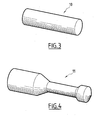
- the method according to the invention consists first of all in shearing a bar having a cylindrical section for obtain a plot 10 of generally cylindrical shape with straight generator, as shown in Fig. 3.
- This piece 10 has a determined length and thickness depending on the mass of the rod to be obtained.
- the piece 10 is, depending on the nature of the steel composing it, heated to a temperature above 850 ° C or at a temperature between 750 and 900 ° C.
- the piece 10 thus heated to the desired temperature is transformed for example by hammering or by rolling into a pre-blank 20 shown in Fig. 4 which has a greater length than the piece 10 and a cylindrical cross section and a non-linear director.
- the transformation of the piece 10 into a pre-draft 11 is carried out in performing a longitudinal distribution of the material of the piece 10 to obtain this pre-draft 11 which has in a longitudinal direction more material in the end zones intended respectively to form the head 2 and the foot 6.
- the material is distributed as close as possible to the place where it is will find in the rod 1 finished.
- pre-draft 11 is transformed into a pre-draft 12 represented in FIGS. 8 and 9 by a first set of dies designated in as a whole by the reference 20, shown in Figs. 5 to 7, and the draft 12 is transformed into a raw rod by a second set of dies designated by the general reference 30 and shown in Figs. 10 to 12.
- the blank 12 is obtained without burr and the raw rod is also obtained without burr which allows avoid the dressing phase of the side walls.
- the first game of dies 20 comprises a lower die 21 comprising on its face upper a closed imprint 22 whose shape corresponds to the shape of the blank 12 to be obtained.
- the upper die 23 forms a punch intended to slide in the cavity 22 and, for this purpose, this upper matrix 23 has an external profile corresponding to the internal profile of the imprint 22.
- the underside of the upper die 23 has the shape shown in Fig. 6 and which corresponds to the shape of one of the main faces of the blank 12 to be obtained. It is the same for the bottom of the imprint 22 of the lower matrix 21 which has the shape of the other of the main faces of this draft 12.
- the clearance between the lower dies 21 and upper 23 is comprised between 0.3 and 0.05mm and the imprint 22 of the lower matrix 21 and the upper matrix 23 have the smallest connecting radii possible and which are between 0.5 and 1.5mm.
- the imprint 22 of the lower matrix 21 has a ejection slope between 0.5 and 3 °.
- the pre-blank 11 is placed in the imprint 22 of the matrix lower 21 and the lowering of the upper die 23 forming a punch in this imprint 22 flattens the pre-blank 11 in order to achieve a distribution longitudinal and transverse matter and bring this matter the most to the vertical possible from its position on the final gross connecting rod. Matter moves therefore axially and transversely whatever the areas intended for form the head 2, the body 5 and the foot 6, the most important displacement located at the level of the head 2.
- the material touches the edges of this imprint 22 at about the same time to limit the risk of vertical burrs.
- the second set of dies 30 comprises a lower die 31 provided on its upper face of a closed imprint 32 whose shape corresponds to the shape of the raw rod to obtain, that is to say the general shape of the connecting rod shown in Figs. 1 and 2, without bores 3 and 7.
- the upper die 33 forms a punch intended to slide in the cavity 32 and, for this purpose, this upper matrix 33 has a profile external corresponding to the internal profile of the imprint 32.
- the underside of the upper die 33 has the shape shown in Fig. 11 and which corresponds to the shape of one of the faces main rods to obtain. It is the same for the bottom of the impression 32 which has a shape which corresponds to the shape of the other face main of the raw connecting rod to obtain.
- the play between the lower 21 and upper 33 dies is between 0.3 and 0.05 mm and the imprint 32 of the lower matrix 31 and the upper matrix 33 have the smallest possible connecting radii which are between 0.5 and 1.5mm.
- the side walls of the cavity 32 of the matrix lower 31 has an ejection slope of between 0.5 and 3 °.
- the blank 12 is placed in the cavity 32 of the matrix lower 31 and the lowering of the upper matrix 33 prints in the material the final forms of the raw rod.
- bores 3 and 7 respectively in the head 2 and in the foot 6 are produced for example on a press stamp or by machining with a knockout tool.
- a shot peening operation can also be carried out if the heating of the piece 10 was carried out at a temperature above 800 ° C. in order to to eliminate the scale.
- the connecting rods obtained by the process according to the invention are in steel. This process also makes it possible to obtain rods in cast iron and by sintering.
- the method according to the invention as well as the tools for setting up use of this process make it possible to save material when production of connecting rods which is important given that in the calculation of the price cost of a connecting rod, the price of the material is between a third and a half of the total cost price.
- the method and the device according to the invention make it possible to make connecting rods with significant height differences between the head, soul and foot.
- the head may be thicker than the foot and possibly the soul thinner than the foot.
Landscapes
- Engineering & Computer Science (AREA)
- General Engineering & Computer Science (AREA)
- Mechanical Engineering (AREA)
- Forging (AREA)
- Shafts, Cranks, Connecting Bars, And Related Bearings (AREA)
Abstract
Description
- on chauffe un lopin de longueur et d'épaisseur déterminées en fonction de la masse de la bielle à obtenir,
- on effectue une étape de répartition longitudinale de la matière du lopin pour réaliser une pré-ébauche cylindrique présentant dans une direction longitudinale plus de matière dans les zones d'extrémité destinées à former la tête et le pied,
- on effectue, dans un premier jeu de matrices, une étape de répartition longitudinale et transversale de la matière de la pré-ébauche pour obtenir une ébauche sans bavure,
- on effectue dans un second jeu de matrices une étape de finition par une répartition de la matière longitudinalement, transversalement et en épaisseur de l'ébauche pour obtenir une bielle brute sans bavure, et
- on réalise les alésages de la tête et du pied de la bielle.
- le lopin présente une forme générale cylindrique à génératrice droite,
- le chauffage du lopin est réalisé à une température supérieure à 850°C,
- le chauffage du lopin est réalisé à une température comprise entre 750 et 900°C,
- l'étape de répartition longitudinale de la matière est réalisée par martelage ou par laminage,
- les alésages de la tête et du pied sont réalisés sur une presse à estamper ou par usinage avec un outil à défoncer,
- on réalise après l'étape de finition une étape de grenaillage.
- chaque jeu de matrices comprend une matrice inférieure comportant une empreinte fermée et une matrice supérieure formant poinçon et coulissant dans la matrice inférieure avec un jeu compris entre 0,3 et 0,05mm,
- l'empreinte de la matrice inférieure et la matrice supérieure de chaque jeu de matrices présentent des rayons de raccordement des faces compris enter 0,5 et 1,5mm,
- l'empreinte de la matrice inférieure de chaque jeu de matrices présente une pente d'éjection comprise entre 0,5 et 3°.
- la Fig. 1 est une vue schématique de dessus d'une bielle forgée,
- la Fig. 2 est une vue schématique en coupe selon la ligne 2-2 de la Fig. 1,
- la Fig. 3 est une vue schématique en perspective d'un lopin à partir duquel est réalisée la bielle forgée,
- la Fig. 4 est une vue schématique en perspective d'une pré-ébauche de bielle forgée réalisée à partir du lopin de la Fig. 3,
- la Fig. 5 est une vue schématique en coupe verticale d'un premier jeu de matrices d'un outillage pour réaliser une ébauche de bielle forgée,
- la Fig. 6 est une vue schématique de dessous de la matrice supérieure du premier jeu de matrices,
- la Fig. 7 est une vue schématique de dessus de la matrice inférieure du premier jeu de matrices,
- la Fig. 8 est une vue de dessus d'une ébauche obtenue par le premier jeu de matrices,
- la Fig. 9 est une vue schématique en coupe selon la ligne 9-9 de la Fig. 8,
- la Fig. 10 est une vue schématique en coupe verticale d'un second jeu de matrices d'un outillage conforme à l'invention,
- la Fig. 11 est une vue de dessous de la matrice supérieure du second jeu de matrices,
- la Fig. 12 est une vue schématique de dessus de la matrice inférieure du second jeu de matrices.
Claims (12)
- Procédé de mise en forme d'une bielle forgée (1) du type comprenant une tête (2) munie d'un alésage (3), un corps (5) et un pied (6) muni d'un alésage (7), caractérisé en ce que :on chauffe un lopin (10) de longueur et d'épaisseur déterminées en fonction de la masse de la bielle (1) à obtenir,on effectue une étape de répartition longitudinale de la matière du lopin (10) pour réaliser une pré-ébauche (11) cylindrique présentant dans une direction longitudinale plus de matière dans les zones d'extrémité destinées à former la tête (2) et le pied (6),on effectue dans un premier jeu de matrices (20) une étape de répartition longitudinale et transversale de la matière de la pré-ébauche (11) pour obtenir une ébauche (12) sans bavure,on effectue dans un second jeu de matrices (30) une étape de finition par une répartition de la matière longitudinalement, transversalement et en épaisseur de l'ébauche (12) pour obtenir une bielle brute sans bavure, eton réalise des alésages (3, 7) de la tête (2) et du pied (6) de la bielle (1).
- Procédé selon la revendication 1, caractérisé en ce que le lopin (10) présente une forme générale cylindrique à génératrice droite.
- Procédé selon la revendication 1 ou 2, caractérisé en ce que le chauffage du lopin (10) est réalisé à une température supérieure à 850°C.
- Procédé selon la revendication 1 ou 2, caractérisé en ce que le chauffage du lopin (10) est réalisé à une température comprise entre 750 et 900°C.
- Procédé selon l'une quelconque des revendications 1 à 4, caractérisé en ce que l'étape de répartition longitudinale de la matière est réalisée par martelage ou par laminage.
- Procédé selon l'une quelconque des revendications 1 à 5, caractérisé en ce que les alésages (3, 7) de la tête (2) et du pied (6) sont réalisés par une presse à estamper ou par usinage avec un outil à défoncer.
- Procédé selon l'une quelconque des revendications 1 à 6, caractérisé en ce que l'on réalise après l'étape de finition, une étape de grenaillage.
- Outillage de mise en forme d'une bielle forgée (1) pour la mise en oeuvre du procédé selon l'une quelconque des revendications précédentes, caractérisé en ce qu'il comprend, en outre, un premier jeu de matrices (20) de répartition longitudinale et transversale de la matière d'une pré-ébauche (11) pour obtenir une ébauche (12) sans bavure et un second jeu de matrices (30) de finition par une répartition de la matière longitudinalement, transversalement et en épaisseur de l'ébauche (12) pour obtenir une bielle brute sans bavure.
- Outillage selon la revendication 8, caractérisé en ce que chaque jeu de matrices (20, 30) comprend une matrice inférieure (21, 31) comportant une empreinte (22, 32) fermée et une matrice supérieure (23, 33) formant poinçon et coulissant dans la matrice inférieure (21, 31) avec un jeu compris enter 0,3 et 0,05mm.
- Outillage selon la revendication 8 ou 9, caractérisé en ce que l'empreinte (22, 32) de la matrice inférieure (21, 31) et la matrice supérieure (23, 33) de chaque jeu de matrices (20, 30) présentent des rayons de raccordement des faces compris entre 0,5 et 1,5mm.
- Outillage selon l'une quelconque des revendications 8 à 10, caractérisé en ce que l'empreinte (22, 32) de la matrice inférieure (21, 31) de chaque jeu de matrices (20, 30) présente une pente d'éjection comprise entre 0,5 et 3°.
- Bielle forgée pour moteur à combustion interne, caractérisée en ce qu'elle est obtenue par le procédé selon l'une quelconque des revendications 1 à 7.
Applications Claiming Priority (2)
| Application Number | Priority Date | Filing Date | Title |
|---|---|---|---|
| FR0204032A FR2837730B1 (fr) | 2002-03-29 | 2002-03-29 | Procede de mise en forme d'une bielle forgee et outillage pour la mise en oeuvre d'un tel procede |
| FR0204032 | 2002-03-29 |
Publications (3)
| Publication Number | Publication Date |
|---|---|
| EP1350584A2 true EP1350584A2 (fr) | 2003-10-08 |
| EP1350584A3 EP1350584A3 (fr) | 2004-08-04 |
| EP1350584B1 EP1350584B1 (fr) | 2006-11-02 |
Family
ID=27839357
Family Applications (1)
| Application Number | Title | Priority Date | Filing Date |
|---|---|---|---|
| EP03290766A Expired - Lifetime EP1350584B1 (fr) | 2002-03-29 | 2003-03-26 | Procédé de mise en forme d'une bielle forgée et outillage pour la mise en oeuvre d'un tel procédé |
Country Status (4)
| Country | Link |
|---|---|
| EP (1) | EP1350584B1 (fr) |
| AT (1) | ATE344112T1 (fr) |
| DE (1) | DE60309369D1 (fr) |
| FR (1) | FR2837730B1 (fr) |
Cited By (2)
| Publication number | Priority date | Publication date | Assignee | Title |
|---|---|---|---|---|
| CN117300030A (zh) * | 2023-09-25 | 2023-12-29 | 如皋市林达线路金具有限公司 | 一种熔断器端部金具锻造成型工艺 |
| CN120038262A (zh) * | 2025-04-27 | 2025-05-27 | 宁波蜗牛锻造有限公司 | 一种汽车连杆加工用锻造设备及加工工艺 |
Family Cites Families (5)
| Publication number | Priority date | Publication date | Assignee | Title |
|---|---|---|---|---|
| DE2919337A1 (de) * | 1979-05-14 | 1981-01-29 | Msp Ind | Verfahren und vorrichtung zum warmpressen von pleuelkopf-lagerdeckeln |
| DE4329371A1 (de) * | 1993-09-01 | 1995-03-09 | Brockhaus Soehne Gmbh & Co Kg | Verfahren zur Herstellung von Pleuelstangen durch gratloses Schmieden |
| US5544413A (en) * | 1994-06-10 | 1996-08-13 | Omni Forge, Inc. | Method and apparatus for manfacturing a flashless metal connecting rod |
| JP3553344B2 (ja) * | 1997-11-11 | 2004-08-11 | 本田技研工業株式会社 | コンロッドの成形方法 |
| US6151948A (en) * | 1999-02-26 | 2000-11-28 | Msp Industries Corporation | Methods and apparatuses for producing complex-shaped metal parts by forging |
-
2002
- 2002-03-29 FR FR0204032A patent/FR2837730B1/fr not_active Expired - Fee Related
-
2003
- 2003-03-26 AT AT03290766T patent/ATE344112T1/de not_active IP Right Cessation
- 2003-03-26 EP EP03290766A patent/EP1350584B1/fr not_active Expired - Lifetime
- 2003-03-26 DE DE60309369T patent/DE60309369D1/de not_active Expired - Lifetime
Cited By (2)
| Publication number | Priority date | Publication date | Assignee | Title |
|---|---|---|---|---|
| CN117300030A (zh) * | 2023-09-25 | 2023-12-29 | 如皋市林达线路金具有限公司 | 一种熔断器端部金具锻造成型工艺 |
| CN120038262A (zh) * | 2025-04-27 | 2025-05-27 | 宁波蜗牛锻造有限公司 | 一种汽车连杆加工用锻造设备及加工工艺 |
Also Published As
| Publication number | Publication date |
|---|---|
| DE60309369D1 (de) | 2006-12-14 |
| EP1350584B1 (fr) | 2006-11-02 |
| EP1350584A3 (fr) | 2004-08-04 |
| FR2837730A1 (fr) | 2003-10-03 |
| FR2837730B1 (fr) | 2004-10-01 |
| ATE344112T1 (de) | 2006-11-15 |
Similar Documents
| Publication | Publication Date | Title |
|---|---|---|
| US6931906B2 (en) | Method and apparatus for cold forging a trailer hitch receiving housing | |
| CN108472711A (zh) | 用于产生增材制造产品的方法 | |
| US8397597B2 (en) | Rack bar and method for production thereof | |
| US20100299925A1 (en) | Method for forming a gear | |
| Kudo | Towards net-shape forming | |
| US20090205453A1 (en) | Ring gear and manufacturing method for such a ring gear | |
| US9375778B2 (en) | Method for forming forged parts | |
| US20100281941A1 (en) | Core Rod Forging for Precise Internal Geometry | |
| US6735996B2 (en) | Method of making an axle element for a motor vehicle, and shaping die for carrying out the method | |
| EP1350584B1 (fr) | Procédé de mise en forme d'une bielle forgée et outillage pour la mise en oeuvre d'un tel procédé | |
| US2960763A (en) | Method of forging with thin webs | |
| Sadeghi et al. | Precision forging straight and helical spur gears | |
| EP1348501B1 (fr) | Procédé de fabrication d'une bielle forgée et outillage pour la mise en oeuvre de ce procédé | |
| KR100840214B1 (ko) | 액슬용 하우징 제조방법 | |
| WO2017163161A1 (fr) | Ensemble de matrices de finisseur et procédé de forgeage pour fabriquer un entraînement à pignon, et entraînement à pignon | |
| RU2355504C1 (ru) | Способ изготовления осесимметричных деталей из труднодеформируемых малопластичных металлов и сплавов | |
| GB2056894A (en) | Manufacture of rack member for rack and pinion assembly | |
| JP3405372B2 (ja) | 組立用カムロブの製造方法 | |
| JPH0679392A (ja) | 歯車の鍛造方法 | |
| KR20190072841A (ko) | 냉간단조 공법을 이용한 인서트 스크류 제조방법 | |
| US4885927A (en) | Method and apparatus for press forming intricate metallic shapes such as spool valve elements | |
| JP3494349B2 (ja) | ヘリカルギヤの製造方法 | |
| JP4383151B2 (ja) | ヘリカル歯車の製造方法 | |
| JPH0759341B2 (ja) | トランスミッションのシンクロ機構用一体型シンクロクラッチギアの製造法 | |
| JP2008049363A (ja) | 鍛造品の製造方法 |
Legal Events
| Date | Code | Title | Description |
|---|---|---|---|
| PUAI | Public reference made under article 153(3) epc to a published international application that has entered the european phase |
Free format text: ORIGINAL CODE: 0009012 |
|
| AK | Designated contracting states |
Kind code of ref document: A2 Designated state(s): AT BE BG CH CY CZ DE DK EE ES FI FR GB GR HU IE IT LI LU MC NL PT RO SE SI SK TR |
|
| AX | Request for extension of the european patent |
Extension state: AL LT LV MK |
|
| RIN1 | Information on inventor provided before grant (corrected) |
Inventor name: NICLAS, ANDRE |
|
| PUAL | Search report despatched |
Free format text: ORIGINAL CODE: 0009013 |
|
| AK | Designated contracting states |
Kind code of ref document: A3 Designated state(s): AT BE BG CH CY CZ DE DK EE ES FI FR GB GR HU IE IT LI LU MC NL PT RO SE SI SK TR |
|
| AX | Request for extension of the european patent |
Extension state: AL LT LV MK |
|
| RIC1 | Information provided on ipc code assigned before grant |
Ipc: 7B 21K 3/00 B Ipc: 7B 21K 1/76 A |
|
| 17P | Request for examination filed |
Effective date: 20050119 |
|
| 17Q | First examination report despatched |
Effective date: 20050315 |
|
| AKX | Designation fees paid |
Designated state(s): AT BE BG CH CY CZ DE DK EE ES FI FR GB GR HU IE IT LI LU MC NL PT RO SE SI SK TR |
|
| GRAP | Despatch of communication of intention to grant a patent |
Free format text: ORIGINAL CODE: EPIDOSNIGR1 |
|
| GRAS | Grant fee paid |
Free format text: ORIGINAL CODE: EPIDOSNIGR3 |
|
| GRAA | (expected) grant |
Free format text: ORIGINAL CODE: 0009210 |
|
| AK | Designated contracting states |
Kind code of ref document: B1 Designated state(s): AT BE BG CH CY CZ DE DK EE ES FI FR GB GR HU IE IT LI LU MC NL PT RO SE SI SK TR |
|
| PG25 | Lapsed in a contracting state [announced via postgrant information from national office to epo] |
Ref country code: IT Free format text: LAPSE BECAUSE OF FAILURE TO SUBMIT A TRANSLATION OF THE DESCRIPTION OR TO PAY THE FEE WITHIN THE PRESCRIBED TIME-LIMIT;WARNING: LAPSES OF ITALIAN PATENTS WITH EFFECTIVE DATE BEFORE 2007 MAY HAVE OCCURRED AT ANY TIME BEFORE 2007. THE CORRECT EFFECTIVE DATE MAY BE DIFFERENT FROM THE ONE RECORDED. Effective date: 20061102 Ref country code: RO Free format text: LAPSE BECAUSE OF FAILURE TO SUBMIT A TRANSLATION OF THE DESCRIPTION OR TO PAY THE FEE WITHIN THE PRESCRIBED TIME-LIMIT Effective date: 20061102 Ref country code: AT Free format text: LAPSE BECAUSE OF FAILURE TO SUBMIT A TRANSLATION OF THE DESCRIPTION OR TO PAY THE FEE WITHIN THE PRESCRIBED TIME-LIMIT Effective date: 20061102 Ref country code: FI Free format text: LAPSE BECAUSE OF FAILURE TO SUBMIT A TRANSLATION OF THE DESCRIPTION OR TO PAY THE FEE WITHIN THE PRESCRIBED TIME-LIMIT Effective date: 20061102 Ref country code: NL Free format text: LAPSE BECAUSE OF FAILURE TO SUBMIT A TRANSLATION OF THE DESCRIPTION OR TO PAY THE FEE WITHIN THE PRESCRIBED TIME-LIMIT Effective date: 20061102 Ref country code: SK Free format text: LAPSE BECAUSE OF FAILURE TO SUBMIT A TRANSLATION OF THE DESCRIPTION OR TO PAY THE FEE WITHIN THE PRESCRIBED TIME-LIMIT Effective date: 20061102 Ref country code: CZ Free format text: LAPSE BECAUSE OF FAILURE TO SUBMIT A TRANSLATION OF THE DESCRIPTION OR TO PAY THE FEE WITHIN THE PRESCRIBED TIME-LIMIT Effective date: 20061102 Ref country code: IE Free format text: LAPSE BECAUSE OF FAILURE TO SUBMIT A TRANSLATION OF THE DESCRIPTION OR TO PAY THE FEE WITHIN THE PRESCRIBED TIME-LIMIT Effective date: 20061102 Ref country code: SI Free format text: LAPSE BECAUSE OF FAILURE TO SUBMIT A TRANSLATION OF THE DESCRIPTION OR TO PAY THE FEE WITHIN THE PRESCRIBED TIME-LIMIT Effective date: 20061102 |
|
| REG | Reference to a national code |
Ref country code: GB Ref legal event code: FG4D Free format text: NOT ENGLISH |
|
| REG | Reference to a national code |
Ref country code: IE Ref legal event code: FG4D Free format text: LANGUAGE OF EP DOCUMENT: FRENCH |
|
| REG | Reference to a national code |
Ref country code: CH Ref legal event code: EP |
|
| REF | Corresponds to: |
Ref document number: 60309369 Country of ref document: DE Date of ref document: 20061214 Kind code of ref document: P |
|
| PG25 | Lapsed in a contracting state [announced via postgrant information from national office to epo] |
Ref country code: SE Free format text: LAPSE BECAUSE OF FAILURE TO SUBMIT A TRANSLATION OF THE DESCRIPTION OR TO PAY THE FEE WITHIN THE PRESCRIBED TIME-LIMIT Effective date: 20070202 Ref country code: DK Free format text: LAPSE BECAUSE OF FAILURE TO SUBMIT A TRANSLATION OF THE DESCRIPTION OR TO PAY THE FEE WITHIN THE PRESCRIBED TIME-LIMIT Effective date: 20070202 Ref country code: BG Free format text: LAPSE BECAUSE OF FAILURE TO SUBMIT A TRANSLATION OF THE DESCRIPTION OR TO PAY THE FEE WITHIN THE PRESCRIBED TIME-LIMIT Effective date: 20070202 |
|
| PG25 | Lapsed in a contracting state [announced via postgrant information from national office to epo] |
Ref country code: DE Free format text: LAPSE BECAUSE OF FAILURE TO SUBMIT A TRANSLATION OF THE DESCRIPTION OR TO PAY THE FEE WITHIN THE PRESCRIBED TIME-LIMIT Effective date: 20070203 |
|
| PG25 | Lapsed in a contracting state [announced via postgrant information from national office to epo] |
Ref country code: ES Free format text: LAPSE BECAUSE OF FAILURE TO SUBMIT A TRANSLATION OF THE DESCRIPTION OR TO PAY THE FEE WITHIN THE PRESCRIBED TIME-LIMIT Effective date: 20070213 |
|
| PG25 | Lapsed in a contracting state [announced via postgrant information from national office to epo] |
Ref country code: PT Free format text: LAPSE BECAUSE OF FAILURE TO SUBMIT A TRANSLATION OF THE DESCRIPTION OR TO PAY THE FEE WITHIN THE PRESCRIBED TIME-LIMIT Effective date: 20070402 |
|
| NLV1 | Nl: lapsed or annulled due to failure to fulfill the requirements of art. 29p and 29m of the patents act | ||
| GBV | Gb: ep patent (uk) treated as always having been void in accordance with gb section 77(7)/1977 [no translation filed] |
Effective date: 20061102 |
|
| REG | Reference to a national code |
Ref country code: IE Ref legal event code: FD4D |
|
| PLBE | No opposition filed within time limit |
Free format text: ORIGINAL CODE: 0009261 |
|
| STAA | Information on the status of an ep patent application or granted ep patent |
Free format text: STATUS: NO OPPOSITION FILED WITHIN TIME LIMIT |
|
| 26N | No opposition filed |
Effective date: 20070803 |
|
| REG | Reference to a national code |
Ref country code: CH Ref legal event code: PL |
|
| PG25 | Lapsed in a contracting state [announced via postgrant information from national office to epo] |
Ref country code: GB Free format text: LAPSE BECAUSE OF FAILURE TO SUBMIT A TRANSLATION OF THE DESCRIPTION OR TO PAY THE FEE WITHIN THE PRESCRIBED TIME-LIMIT Effective date: 20061102 |
|
| BERE | Be: lapsed |
Owner name: PEUGEOT CITROEN AUTOMOBILES SA Effective date: 20070331 |
|
| PG25 | Lapsed in a contracting state [announced via postgrant information from national office to epo] |
Ref country code: BE Free format text: LAPSE BECAUSE OF NON-PAYMENT OF DUE FEES Effective date: 20070331 |
|
| PG25 | Lapsed in a contracting state [announced via postgrant information from national office to epo] |
Ref country code: MC Free format text: LAPSE BECAUSE OF NON-PAYMENT OF DUE FEES Effective date: 20070331 |
|
| PG25 | Lapsed in a contracting state [announced via postgrant information from national office to epo] |
Ref country code: LI Free format text: LAPSE BECAUSE OF NON-PAYMENT OF DUE FEES Effective date: 20070331 Ref country code: CH Free format text: LAPSE BECAUSE OF NON-PAYMENT OF DUE FEES Effective date: 20070331 |
|
| PG25 | Lapsed in a contracting state [announced via postgrant information from national office to epo] |
Ref country code: GR Free format text: LAPSE BECAUSE OF FAILURE TO SUBMIT A TRANSLATION OF THE DESCRIPTION OR TO PAY THE FEE WITHIN THE PRESCRIBED TIME-LIMIT Effective date: 20070203 |
|
| PG25 | Lapsed in a contracting state [announced via postgrant information from national office to epo] |
Ref country code: EE Free format text: LAPSE BECAUSE OF FAILURE TO SUBMIT A TRANSLATION OF THE DESCRIPTION OR TO PAY THE FEE WITHIN THE PRESCRIBED TIME-LIMIT Effective date: 20061102 |
|
| PG25 | Lapsed in a contracting state [announced via postgrant information from national office to epo] |
Ref country code: CY Free format text: LAPSE BECAUSE OF FAILURE TO SUBMIT A TRANSLATION OF THE DESCRIPTION OR TO PAY THE FEE WITHIN THE PRESCRIBED TIME-LIMIT Effective date: 20061102 Ref country code: LU Free format text: LAPSE BECAUSE OF NON-PAYMENT OF DUE FEES Effective date: 20070326 |
|
| PGFP | Annual fee paid to national office [announced via postgrant information from national office to epo] |
Ref country code: FR Payment date: 20090327 Year of fee payment: 7 |
|
| PG25 | Lapsed in a contracting state [announced via postgrant information from national office to epo] |
Ref country code: HU Free format text: LAPSE BECAUSE OF FAILURE TO SUBMIT A TRANSLATION OF THE DESCRIPTION OR TO PAY THE FEE WITHIN THE PRESCRIBED TIME-LIMIT Effective date: 20070503 Ref country code: TR Free format text: LAPSE BECAUSE OF FAILURE TO SUBMIT A TRANSLATION OF THE DESCRIPTION OR TO PAY THE FEE WITHIN THE PRESCRIBED TIME-LIMIT Effective date: 20061102 |
|
| REG | Reference to a national code |
Ref country code: FR Ref legal event code: ST Effective date: 20101130 |
|
| PG25 | Lapsed in a contracting state [announced via postgrant information from national office to epo] |
Ref country code: FR Free format text: LAPSE BECAUSE OF NON-PAYMENT OF DUE FEES Effective date: 20100331 |