EP1349718B1 - Ribbon for a saw - Google Patents
Ribbon for a saw Download PDFInfo
- Publication number
- EP1349718B1 EP1349718B1 EP01272655A EP01272655A EP1349718B1 EP 1349718 B1 EP1349718 B1 EP 1349718B1 EP 01272655 A EP01272655 A EP 01272655A EP 01272655 A EP01272655 A EP 01272655A EP 1349718 B1 EP1349718 B1 EP 1349718B1
- Authority
- EP
- European Patent Office
- Prior art keywords
- saw
- band
- saw band
- ribbon
- individual
- Prior art date
- Legal status (The legal status is an assumption and is not a legal conclusion. Google has not performed a legal analysis and makes no representation as to the accuracy of the status listed.)
- Expired - Lifetime
Links
Images


Classifications
-
- B—PERFORMING OPERATIONS; TRANSPORTING
- B28—WORKING CEMENT, CLAY, OR STONE
- B28D—WORKING STONE OR STONE-LIKE MATERIALS
- B28D1/00—Working stone or stone-like materials, e.g. brick, concrete or glass, not provided for elsewhere; Machines, devices, tools therefor
- B28D1/02—Working stone or stone-like materials, e.g. brick, concrete or glass, not provided for elsewhere; Machines, devices, tools therefor by sawing
- B28D1/12—Saw-blades or saw-discs specially adapted for working stone
- B28D1/127—Straight, i.e. flat, saw blades; strap saw blades
- B28D1/128—Straight, i.e. flat, saw blades; strap saw blades with exchangeable cutter bits or cutter segments
-
- B—PERFORMING OPERATIONS; TRANSPORTING
- B28—WORKING CEMENT, CLAY, OR STONE
- B28D—WORKING STONE OR STONE-LIKE MATERIALS
- B28D1/00—Working stone or stone-like materials, e.g. brick, concrete or glass, not provided for elsewhere; Machines, devices, tools therefor
- B28D1/02—Working stone or stone-like materials, e.g. brick, concrete or glass, not provided for elsewhere; Machines, devices, tools therefor by sawing
- B28D1/12—Saw-blades or saw-discs specially adapted for working stone
- B28D1/124—Saw chains; rod-like saw blades; saw cables
- B28D1/125—Saw chains; rod-like saw blades; saw cables with exchangeable cutter bits or cutter segments
Definitions
- the invention relates to a saw band for a band saw according to the preamble of the main claim and a band saw with an inventive Bandsaw.
- Band saws and the endless saw bands running around them become Cutting different materials used. Both in the meat processing industry, as well as in the wood and metal industry Band saws for cutting off semi-finished products but also for precise cuts used.
- the endless rotating saw band offers numerous advantages. First is the feed direction of a band saw always parallel to the bending direction of the Saw band oriented and thus enables a very flexible cut. at A chain saw has a vertical feed and bend direction oriented towards each other. Therefore the circulation of the chain must inevitably Cutting plane are performed, which requires a certain width of the sword and a significant impairment in terms of the cut, means especially with regard to the cutting radii. Furthermore, the Saw band do not have their own pressure resistance, as it is always under one certain tension is pulled through the cut.
- a circular or Jigsaw must therefore have a comparatively thicker saw blade because the cutting pressure must also be maintained as a pure pressure load. Furthermore, the modern band saws have their own freedom in the cutting of great advantage. The cut can be oriented along almost any orientation Straight lines in the room.
- the cooling can be Carry out the example in a simple way using a liquid bath. Wiping cleaning elements are almost anywhere in the endless circulation of the saw band attachable.
- a major disadvantage of conventional band saws is the vulnerability of the Saw band for defects.
- the necessary flexibility of the saw band is necessary a comparatively thin material thickness, which is why saw bands measured on their specific cutting use a comparatively short service life exhibit.
- a saw blade with a high quality cutting material e.g. B. a diamond assembly in which Usually not.
- a saw band of a band saw is known from US Pat. No. 2,368,092, in which a Large number of individual, diamond-tipped tooth segments on a one-piece Carrier tape are applied. Although defective tooth segments this Saw band could be replaced with a suitable tool this solution is not convincing in terms of its robustness.
- the carrier tape must endure high cutting and centrifugal forces and may still for purposes of preservation its flexibility has only a low material thickness. In addition, it will still weakened by a large number of transverse bores which are necessary for the Connections with the tooth segments are necessary.
- this solution requires a guide rail in the band saw work area, to line up the tooth segments cleanly and during the Stabilize material interference. Especially when cutting rocks there is a large amount of dust, which is an effective one Lubrication of the guide rail difficult. For this reason Stone cutting machines today usually with high-speed Diamond cutting discs operated as a wet cutting system.
- the object of the invention to provide a band saw, which a longer average service life of a saw band at the same time has comparatively low stand costs and thus the advantages of Band sawing, especially in relation to circular saws.
- the object is achieved by a saw band mentioned type, in which the saw band directly from individual links connected in a form-fitting manner and arranged in the running direction consists. Furthermore, a band saw with a saw band according to the invention Subject of the invention.
- the decisive advantage of the saw band according to the invention is that the saw band can be disassembled into individual links. That way you can defective links can be easily replaced.
- the average service life of a Saw band is therefore no longer of a mostly accidental one Individual errors in the entire rotation of the saw band depend, but will determined by the average service life of the individual links.
- the probability of failure of a conventional saw band is determined the sum of the failure probabilities of the individual teeth.
- the breakdown of the saw band according to the invention into individual with each other connected links arranged one behind the other in the running direction enables the Reduction of the probability of failure of the saw band to that Probability of failure of a single limb, which results from the Sum of the failure probabilities of the individual teeth results.
- points a saw band according to the invention only a fraction of the Failure probability of a conventional saw band and therefore a much longer service life.
- the individual links with diamond particles or diamond segments. Falls one of the high-quality equipped Links of the saw band, it can advantageously be easily replaced and the entire saw band does not have to be discarded.
- a useful further development of the saw band according to the invention provides that the individual links are articulated together.
- the individual links are articulated together.
- By a articulated connection of the individual links it is possible to link the single link more robust, if necessary completely stiff.
- the service life of the saw band additionally.
- the band saw's own flexible version of the Saw band and the resulting flexible, thin The design of the saw band is no longer necessary.
- Diamond segments are usually made up of sintered components Diamond dust and a binder made. These are natural Segments rigid and due to their size can not be with one connect conventional flexible saw band.
- Saw band is articulated with each other due to the usability of rigid connected links possible for the first time, a band saw with a To operate diamond segments equipped saw band.
- Another embodiment of the saw band according to the invention provides that the individual links are flexible in themselves and thus an articulated connection of the individual links does not represent an imperative. This can in particular with less heavy-duty cutting tasks, such as Example in the meat industry.
- the positive connection between the individual links is special easy to maintain if it is detachable.
- the saw blade can be so by simply hanging and unhooking individual links disassemble.
- An advantageous development of the invention provides that the each link at least one recess and at least one Have holding element, the holding element of a link in each case Recesses a neighboring link and in this way a tensile connection between the adjacent links is formed.
- the members under tension are expediently removed from the association do not remove the saw band.
- Such an execution is extreme inexpensive, because additional connecting elements between the individual Limbs can be omitted. It also reduces the effort for that Replacement of individual links on a simple hooking and unhooking. moreover no tools are required for this.
- Each link expediently has Longitudinal direction of the saw band on one side and a holding element a recess on the opposite side. That way they can Holding elements of the identically designed links each in the recess of the neighboring link.
- a band saw with a saw band according to the invention that runs vertically, is particularly useful for cutting stones.
- plates stones can be placed on the usually perpendicular to the The running direction of the saw blade-oriented base plate can be divided. Since the does not create dust, as when using a circular saw or If the cutting disc is swirled heavily in the dry cutting process, the Any dust that arises can be sucked off almost completely.
- the saw band has no guide in the cutting area.
- the link 1 of a saw band according to the invention shown in FIG. 1 is shown in FIG provided with the reference number 1 in its entirety.
- a holding element 2 In the direction of the Saw band on one side of the link 1 is a holding element 2 and on the opposite side in the direction of a recess 3, the a holding piece 3a is limited in the running direction.
- the holding element 2 and that Holding piece 3a each extend transversely to the running direction of the saw band and parallel in the feed direction.
- the recess 3 is a segment of a circle executed, the secant of the segment of a circle having a length X which passing the holding element 2 of an adjacent link 1 allows.
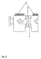
- connection of two links 1 takes place in the manner shown in FIG. 2.
- the holding element 2 of a link 1 is shaped by the segment of a circle Recess 3 guided and then to abut the holding piece 3a brought.
- the result is a form-fit connection that is resilient to tension is articulated out of the cutting plane.
- the holding element 2 and the recess 3 and the holding piece 3a are as can be seen from Figure 4, carried out so cranked that the System of the holding element 2 on the holding piece 3a no offset between results in the cutting of the saw band formed as diamond segments 6.
- the neck of the T-shaped holding element 2 here forms a recess 8 for the Installation of the holding piece 3a.
- part of the recess 3 is transverse to Running direction and approximately parallel to the feed direction of the saw band itself extending recess 9 formed in which the holding element 2 on the Holding piece 3a comes to the plant.
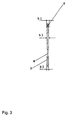
- the cross section shown in Figure 3 through a saw band shows that the b1 designated thickness of the saw band on the diamond segment 6 is greater than the thickness b3 present in the middle of the link 1 and also as that on the Guide section 7 present thickness b2.
Landscapes
- Engineering & Computer Science (AREA)
- Mining & Mineral Resources (AREA)
- Mechanical Engineering (AREA)
- Sawing (AREA)
- Processing Of Stones Or Stones Resemblance Materials (AREA)
- Decoration Of Textiles (AREA)
- Polishing Bodies And Polishing Tools (AREA)
- Transition And Organic Metals Composition Catalysts For Addition Polymerization (AREA)
- Adhesive Tapes (AREA)
Abstract
Description
Die Erfindung betrifft ein Sägeband für eine Bandsäge nach dem Oberbegriff des Hauptanspruchs und eine Bandsäge mit einem erfindungsgemäßen Sägeband.The invention relates to a saw band for a band saw according to the preamble of the main claim and a band saw with an inventive Bandsaw.
Bandsägen und die darin umlaufenden, endlosen Sägebänder werden zum Zerteilen unterschiedlichster Materialien genutzt. Sowohl in der fleischverarbeitenden Industrie, als auch in der Holz- und Metallindustrie werden Bandsägen zum Abtrennen von Halbzeugen aber auch für genaue Schnitte benutzt. Das endlos umlaufende Sägeband bietet zahlreiche Vorteile. Zunächst ist die Vorschubrichtung einer Bandsäge stets parallel zur Biegerichtung des Sägebandes orientiert und ermöglicht so eine sehr flexible Schnittführung. Bei einer Kettensäge sind Vorschubrichtung und Biegerichtung senkrecht zueinander orientiert. Daher muß der Umlauf der Kette zwangsläufig in der Schnittebene geführt werden, was eine gewisse Breite des Schwertes bedingt und eine wesentliche Beeinträchtigung bezüglich der Schnittführung, insbesondere bezüglich der Schnittradien bedeutet. Weiterhin muß das Sägeband keine eigene Druckbelastbarkeit aufweisen, da es stets unter einer gewissen Zugspannung durch den Schnitt gezogen wird. Eine Kreis- oder Stichsäge muß daher ein vergleichsweise dickeres Sägeblatt aufweisen, weil dem Schnittdruck auch als reine Druckbelastung Stand gehalten werden muß. Weiterhin ist die modernen Bandsägen eigene Freiheit in der Schnittführung von großem Vorteil. Der Schnitt kann nahezu entlang jeder beliebig orientierten Geraden im Raum geführt werden. Band saws and the endless saw bands running around them become Cutting different materials used. Both in the meat processing industry, as well as in the wood and metal industry Band saws for cutting off semi-finished products but also for precise cuts used. The endless rotating saw band offers numerous advantages. First is the feed direction of a band saw always parallel to the bending direction of the Saw band oriented and thus enables a very flexible cut. at A chain saw has a vertical feed and bend direction oriented towards each other. Therefore the circulation of the chain must inevitably Cutting plane are performed, which requires a certain width of the sword and a significant impairment in terms of the cut, means especially with regard to the cutting radii. Furthermore, the Saw band do not have their own pressure resistance, as it is always under one certain tension is pulled through the cut. A circular or Jigsaw must therefore have a comparatively thicker saw blade because the cutting pressure must also be maintained as a pure pressure load. Furthermore, the modern band saws have their own freedom in the cutting of great advantage. The cut can be oriented along almost any orientation Straight lines in the room.
Je nach zu schneidender Materialdicke, der Materialbeschaffenheit, der Länge des endlosen Umlaufes des Sägebandes und dem Sägebandmaterial lassen sich mit einer Bandsäge auch außerordentlich hohe Schnittgeschwindigkeiten realisieren. Anders als bei einer Kreissäge ist bei einer Bandsäge die Zeit zwischen periodisch aufeinanderfolgenden Eingriffen eines Sägeblattstückes in der Regel länger. Eine Kühlung und Reinigung des Sägebandes ist daher auch technisch sehr viel einfacher und effektiver zu lösen. Die Kühlung läßt sich zum Beispiel auf einfache Weise mittels eines Flüssigkeitsbades herbeiführen. Abstreifende Reinigungselemente sind nahezu an beliebiger Stelle des endlosen Umlaufes des Sägebandes anbringbar.Depending on the material thickness to be cut, the material properties, the length of the endless circulation of the saw band and the band material extremely high cutting speeds with a band saw realize. Unlike a circular saw, time is different with a band saw between periodically successive interventions of a piece of saw blade in usually longer. Cooling and cleaning the saw band is therefore also technically much easier and more effective to solve. The cooling can be Carry out the example in a simple way using a liquid bath. Wiping cleaning elements are almost anywhere in the endless circulation of the saw band attachable.
Ein weiterer großer Vorteil der Bandsäge gegenüber einer Kreissäge ist in der sehr viel einfacheren Spanabfuhr zu sehen. Während die Kreissäge die einzelnen Späne nahezu unkontrolliert in tangentialer Richtung des aus dem Schnitt heraustretenden Sägeblattes wegschleudert, wird das zerspante Material von dem Sägeband der Bandsäge in die meist anschließende Reinigungsvorrichtung gradlinig transportiert. Dieser Vorteil kommt vor allem bei zu zerschneidenden Materialien zum Tragen, die beim Sägen sehr viel Staub freisetzen. Hierzu zählen beispielsweise Steine. Aus Gründen der Staubentwicklung müssen derartige Güter in der Regel unter dem Zusatz von bindendem Wasser im Schnittbereich gesägt werden. Aus mehreren Gründen ist der Zusatz von Wasser in der Regel jedoch nicht erwünscht. Zum einen entsteht ein Schlamm, der sich als hartnäckiger Schmutz in der gesamten Umgebung des Sägevorganges, beispielsweise einer Kreissäge, festsetzt. Zum anderen kann insbesondere bei kalter Witterung der Einsatz von Wasser als Staubbindemittel für den Bedienenden einer Kreissäge höchst unangenehm sein.Another big advantage of the band saw compared to a circular saw is that to see much easier chip evacuation. While the circular saw the individual chips almost uncontrolled in the tangential direction from the If the cut saw blade is thrown away, it will be cut Material from the band saw band saw into the mostly subsequent one Cleaning device transported straight. This advantage comes above all to cut materials to carry, which when sawing a lot of dust release. These include stones, for example. Because of Such goods usually have to be added with the addition of binding water in the cutting area. For many reasons the addition of water is usually not desirable. On the one hand creates a mud that turns out to be stubborn dirt throughout Surrounds the sawing process, for example a circular saw. To the others, especially in cold weather, the use of water as Dust binder extremely unpleasant for the operator of a circular saw his.
Ein großer Nachteil gängiger Bandsägen liegt jedoch in der Anfälligkeit des Sägebandes für Defekte. Die notwendige Flexibilität des Sägebandes bedingt eine vergleichsweise dünne Materialstärke, weshalb Sägebänder gemessen an ihrem spezifischen Schnitteinsatz eine vergleichsweise kurze Standzeit aufweisen. Bereits ein Fehler in einem Sägeband, zum Beispiel ein ausgebrochener Zahn, macht das Auswechseln des gesamten Bandes erforderlich. Aus diesem Grund lohnt sich eine Ausstattung eines Sägeblattes mit einem hochwertigen Schneidmaterial z. B. einer Diamantbestückung, in der Regel nicht.A major disadvantage of conventional band saws is the vulnerability of the Saw band for defects. The necessary flexibility of the saw band is necessary a comparatively thin material thickness, which is why saw bands measured on their specific cutting use a comparatively short service life exhibit. Already a mistake in a saw band, for example a broken tooth, makes the replacement of the entire band required. For this reason, it is worth equipping a saw blade with a high quality cutting material e.g. B. a diamond assembly in which Usually not.
Aus US 2 368 092 ist ein Sägeband einer Bandsäge bekannt, bei dem eine Vielzahl einzelner, diamant-bestückter Zahnsegmente auf einem einteiligen Trägerband appliziert sind. Wenngleich schadhafte Zahnsegmente dieses Sägebandes mit geeignetem Werkzeug ausgetauscht werden könnten, kann diese Lösung hinsichtlich ihrer Robustheit nicht überzeugen. Das Trägerband muß hohe Schnitt- und Fliehkräfte ertragen und darf dennoch zwecks Erhaltung seiner Flexibilität nur eine geringe Materialstärke aufweisen. Zusätzlich wird es noch durch eine Vielzahl von Querborungen geschwächt, die für die Verbindungen mit den Zahnsegmenten notwendig sind. Darüber hinaus erfordert diese Lösung eine Führungsschiene im Arbeitsbereich der Bandsäge, um die Zahnsegmente sauber aneinander zu reihen und während des Materialeingriffs zu stabilisieren. Insbesondere beim Zertrennen von Gestein kommt es zu einer großen Staubentwicklung, welche eine wirksame Schmierung der Führungsschiene erschwert. Aus diesem Grund werden Steintrennmaschinen heute in der Regel mit schnellaufenden Diamanttrennscheiben als Naßschneidesystem betrieben.A saw band of a band saw is known from US Pat. No. 2,368,092, in which a Large number of individual, diamond-tipped tooth segments on a one-piece Carrier tape are applied. Although defective tooth segments this Saw band could be replaced with a suitable tool this solution is not convincing in terms of its robustness. The carrier tape must endure high cutting and centrifugal forces and may still for purposes of preservation its flexibility has only a low material thickness. In addition, it will still weakened by a large number of transverse bores which are necessary for the Connections with the tooth segments are necessary. Furthermore this solution requires a guide rail in the band saw work area, to line up the tooth segments cleanly and during the Stabilize material interference. Especially when cutting rocks there is a large amount of dust, which is an effective one Lubrication of the guide rail difficult. For this reason Stone cutting machines today usually with high-speed Diamond cutting discs operated as a wet cutting system.
Ausgehend von den vorbeschriebenen Problemen und Nachteilen im Stand der Technik ist es die Aufgabe der Erfindung eine Bandsäge zu schaffen, welche eine höhere mittlere Standzeit eines Sägebandes bei gleichzeitig vergleichsweise niedrigen Standkosten aufweist und so die Vorteile des Bandsägens, insbesondere gegenüber dem Kreissägen nutzbar macht.Based on the problems and disadvantages described in the state of the Technology is the object of the invention to provide a band saw, which a longer average service life of a saw band at the same time has comparatively low stand costs and thus the advantages of Band sawing, especially in relation to circular saws.
Erfindungsgemäß wird die Aufgabe durch ein Sägeband der eingangs genannten Art gelöst, bei welchem das Sägeband aus einzelnen direkt formschlüssig miteinander verbundenen, in Laufrichtung angeordneten Gliedern besteht. Weiterhin ist eine Bandsäge mit einem erfindungsgemäßen Sägeband Gegenstand der Erfindung.According to the invention, the object is achieved by a saw band mentioned type, in which the saw band directly from individual links connected in a form-fitting manner and arranged in the running direction consists. Furthermore, a band saw with a saw band according to the invention Subject of the invention.
Der entscheidende Vorteil des erfindungsgemäßen Sägebandes liegt darin, daß das Sägeband in einzelne Glieder zerlegt werden kann. Auf diese Weise können defekte Glieder einfach ausgetauscht werden. Die mittlere Standzeit eines Sägebandes ist daher nicht mehr von einem meist zufällig eintretenden Einzelfehler in dem gesamten Umlauf des Sägebandes abhängig, sondern wird durch die mittlere Standzeit der Einzelglieder bestimmt. Die Ausfallwahrscheinlichkeit eines herkömmlichen Sägebandes bestimmt sich aus der Summe der Ausfallwahrscheinlichkeiten der Einzelzähne. Die erfindungsgemäße Aufgliederung des Sägebandes in einzelne miteinander verbundene, in Laufrichtung hintereinander angeordnete Glieder ermöglicht die Reduktion der Ausfallwahrscheinlichkeit des Sägebandes auf die Ausfallwahrscheinlichkeit eines einzelnen Gliedes, die sich wieder aus der Summe der Ausfallwahrscheinlichkeiten der Einzelzähne ergibt. Folglich weist ein erfindungsgemäßes Sägeband nur einen Bruchteil der Ausfallwahrscheinlickeit eines herkömmlichen Sägebandes auf und hat daher eine wesentlich höhere Standzeit.The decisive advantage of the saw band according to the invention is that the saw band can be disassembled into individual links. That way you can defective links can be easily replaced. The average service life of a Saw band is therefore no longer of a mostly accidental one Individual errors in the entire rotation of the saw band depend, but will determined by the average service life of the individual links. The The probability of failure of a conventional saw band is determined the sum of the failure probabilities of the individual teeth. The breakdown of the saw band according to the invention into individual with each other connected links arranged one behind the other in the running direction enables the Reduction of the probability of failure of the saw band to that Probability of failure of a single limb, which results from the Sum of the failure probabilities of the individual teeth results. Hence points a saw band according to the invention only a fraction of the Failure probability of a conventional saw band and therefore a much longer service life.
Aufgrund der hohen Standzeit ist es mit dem erfindungsgemäßen Sägeband wirtschaftlich, die einzelnen Glieder mit einer Bestückung mit Diamantteilchen oder Diamantsegmenten zu versehen. Fällt eines der hochwertig bestückten Glieder des Sägebandes aus, kann es vorteilhaft einfach ausgewechselt werden und es muß nicht das gesamte Sägeband verworfen werden.Because of the long service life, it is with the saw band according to the invention economical, the individual links with diamond particles or diamond segments. Falls one of the high-quality equipped Links of the saw band, it can advantageously be easily replaced and the entire saw band does not have to be discarded.
Eine sinnvolle Weiterbildung des erfindungsgemäßen Sägebandes sieht vor, daß die einzelnen Glieder gelenkig miteinander verbunden sind. Durch eine gelenkige Verbindung der einzelnen Glieder ist es möglich, das Einzelglied widerstandsfähiger auszuführen, gegebenenfalls vollkommen steif. In vorteilhafter Weise erhöht sich durch die robuste Ausführung der gelenkig miteinander verbundenen Einzelglieder die Standzeit des Sägebandes zusätzlich. Die bisher der Bandsäge eigene flexible Ausführung des Sägebandes und die sich daraus zwingend ergebende biegsame, dünne Bauform des Sägebandes ist so nicht mehr notwendig.A useful further development of the saw band according to the invention provides that the individual links are articulated together. By a articulated connection of the individual links it is possible to link the single link more robust, if necessary completely stiff. In advantageously increases due to the robust design of the articulated interconnected individual links the service life of the saw band additionally. The band saw's own flexible version of the Saw band and the resulting flexible, thin The design of the saw band is no longer necessary.
Vor allem im Hinblick auf eine, insbesondere beim Zertrennen von Steinen bzw. Keramiken zweckmäßige Bestückung eines Sägebandes mit Diamantsegmenten ist eine erfindungsgemäß gelenkige Verbindung zwischen einzelnen starren Gliedern ein großer technischer Zugewinn. Die einzelnen Diamantsegmente werden in der Regel als Sinterbauteil, bestehend aus Diamantstaub und einem Bindemittel hergestellt. Naturgemäß sind diese Segmente starr und lassen sich aufgrund ihrer Größe nicht mit einem herkömmlichen flexiblen Sägeband verbinden. Mit dem erfindungsgemäßen Sägeband ist es aufgrund der Verwendbarkeit von starren gelenkig miteinander verbundenen Gliedern erstmals möglich, eine Bandsäge mit einem mit Diamantsegmenten bestückten Sägeband zu betreiben.Especially with regard to one, especially when cutting stones or Appropriate equipment for a saw band with ceramics Diamond segments is an articulated connection between individual rigid links a great technical gain. The single ones Diamond segments are usually made up of sintered components Diamond dust and a binder made. These are natural Segments rigid and due to their size can not be with one connect conventional flexible saw band. With the invention Saw band is articulated with each other due to the usability of rigid connected links possible for the first time, a band saw with a To operate diamond segments equipped saw band.
Eine andere Ausführungsform des erfindungsgemäßen Sägebandes sieht vor, daß die einzelnen Glieder in sich flexibel sind und so eine gelenkige Verbindung der einzelnen Glieder miteinander keine zwingende Notwendigkeit darstellt. Dies kann insbesondere bei weniger hoch belastenden Schneidaufgaben, wie zum Beispiel in der Fleischindustrie, von Vorteil sein.Another embodiment of the saw band according to the invention provides that the individual links are flexible in themselves and thus an articulated connection of the individual links does not represent an imperative. This can in particular with less heavy-duty cutting tasks, such as Example in the meat industry.
Die formschlüssige Verbindung zwischen den einzelnen Gliedern ist besonders wartungsfreundlich, wenn sie lösbar ausgebildet ist. Das Sägeblatt läßt sich so durch einfaches Ein- und Aushängen einzelner Glieder montieren bzw. demontieren. Eine vorteilhafte Weiterbildung der Erfindung sieht vor, daß die einzelnen Glieder jeweils mindestens eine Ausnehmung und mindestens ein Halteelement aufweisen, wobei das Halteelement eines Gliedes jeweils in eine Ausnehmung eines benachbarten Gliedes eingreift und auf diese Weise eine zugfeste Verbindung zwischen den benachbarten Gliedern gebildet wird. Zweckmäßig lassen sich die unter Zug befindlichen Glieder aus dem Verband des Sägebandes nicht entfernen. Eine derartige Ausführung ist äußerst kostengünstig, da weitere Verbindungselemente zwischen den einzelnen Gliedern entfallen können. Außerdem reduziert sich der Aufwand für das Auswechseln einzelner Glieder auf ein einfaches Ein- und Aushängen. Zudem wird hierzu kein Werkzeug benötigt. Zweckmäßig besitzt jedes Glied in Längsrichtung des Sägebandes auf der einen Seite ein Halteelement und auf der gegenüberliegenden Seite eine Ausnehmung. Auf diese Weise können die Halteelemente der identisch ausgeführten Glieder jeweils in die Ausnehmung des benachbarten Gliedes eingreifen.The positive connection between the individual links is special easy to maintain if it is detachable. The saw blade can be so by simply hanging and unhooking individual links disassemble. An advantageous development of the invention provides that the each link at least one recess and at least one Have holding element, the holding element of a link in each case Recesses a neighboring link and in this way a tensile connection between the adjacent links is formed. The members under tension are expediently removed from the association do not remove the saw band. Such an execution is extreme inexpensive, because additional connecting elements between the individual Limbs can be omitted. It also reduces the effort for that Replacement of individual links on a simple hooking and unhooking. moreover no tools are required for this. Each link expediently has Longitudinal direction of the saw band on one side and a holding element a recess on the opposite side. That way they can Holding elements of the identically designed links each in the recess of the neighboring link.
Um ein Durchrutschen des Sägebandes am Antrieb oder an Laufrädern der Bandsäge zu vermeiden, ist es sinnvoll, wenn mindestens einige der Glieder Ausnehmungen aufweisen, in die Mitnehmerelemente von Laufrädern oder Antriebsrädern eingreifen können.To prevent the saw band from slipping on the drive or the wheels of the To avoid band sawing, it makes sense if at least some of the links Have recesses in the driver elements of impellers or Can engage drive wheels.
Eine Bandsäge mit einem erfindungsgemäßen Sägeband, das vertikal verläuft, ist insbesondere für das Zerteilen von Steinen sinnvoll. Die meist als Platten vorliegenden Steine können zweckmäßig auf der in der Regel senkrecht zur Laufrichtung des Sägebandes orientierten Grundplatte zerteilt werden. Da der entstehende Staub nicht, wie bei der Verwendung einer Kreissäge oder Trennscheibe im Trockenschnittverfahren stark verwirbelt wird, kann der entstehende Staub nahezu rückstandslos abgesaugt werden.A band saw with a saw band according to the invention that runs vertically, is particularly useful for cutting stones. Mostly as plates stones can be placed on the usually perpendicular to the The running direction of the saw blade-oriented base plate can be divided. Since the does not create dust, as when using a circular saw or If the cutting disc is swirled heavily in the dry cutting process, the Any dust that arises can be sucked off almost completely.
Zur Erhöhung der Schnittgenauigkeit ist es sinnvoll, wenn das in der Regel endlose Sägeband mindestens über einen Teil des Umlaufes mittels einer Führungsschiene geführt wird. Hierdurch wird auch das Laufverhalten der gesamten Bandsäge beruhigt und der Verschleiß involvierter Bauteile verringert.To increase the cutting accuracy, it makes sense if that is usually the case endless saw band over at least part of the circulation by means of a Guide rail is guided. This also changes the running behavior of the entire band saw calms down and the wear on the components involved is reduced.
Um kleine Radien besser schneiden zu können, kann es zudem von Vorteil sein, wenn das Sägeband im Schnittbereich keine Führung aufweist.In order to be able to cut small radii better, it can also be advantageous if the saw band has no guide in the cutting area.
Im folgenden wird ein spezielles Ausführungsbeispiel eines Gliedes eines Sägebands unter Bezugnahme auf Zeichnungen zur Verdeutlichung der Erfindung näher beschrieben. Es zeigen:
- Fig. 1
- eine Draufsicht auf ein Glied eines erfindungsgemäßen Sägebands,
- Fig. 2
- eine Draufsicht auf die Verbindung zweier Glieder eines erfindungsgemäßen Sägebands,
- Fig. 3
- ein Schnitt durch ein erfindungsgemäßes Sägeband und
- Fig. 4
- eine Sicht von vorne auf ein Glied eines erfindungsgemäßen Sägebands.
- Fig. 1
- a plan view of a link of a saw band according to the invention,
- Fig. 2
- a plan view of the connection of two links of a saw band according to the invention,
- Fig. 3
- a section through a saw band according to the invention and
- Fig. 4
- a front view of a link of a saw band according to the invention.
Das in Figur 1 dargestellte Glied 1 eines erfindungsgemäßen Sägebands ist in
seiner Gesamtheit mit dem Bezugszeichen 1 versehen. In Laufrichtung des
Sägebands auf einer Seite des Gliedes 1 befindet sich ein Halteelement 2 und
auf der in Laufrichtung gegenüberliegenden Seite eine Ausnehmung 3, die von
einem Haltestück 3a in Laufrichtung begrenzt wird. Das Halteelement 2 und das
Haltestück 3a erstrecken sich jeweils quer zur Laufrichtung des Sägebandes
und parallel in Vorschubrichtung. Die Ausnehmung 3 ist als Kreissegment
ausgeführt, wobei die Sekante des Kreissegments eine Länge X aufweist, die
das Hindurchführen des Halteelements 2 eines benachbarten Gliedes 1
ermöglicht. In etwa in der Mitte des Gliedes 1 befindet sich eine Ausnehmung 5,
die eine Führung des Sägebandes mittels an Laufrädern oder Antriebsrädern
der Bandsäge angebrachten Mitnehmerelementen ermöglicht. An dem in
Vorschubrichtungrichtung weisenden Ende des Gliedes 1 des Sägebandes
befindet sich eine diamantbestücktes Segment 6. Auf dem gegenüberliegenden
Ende des Gliedes befindet sich beidseitig eine sich in Laufrichtung des
Sägebandes erstreckende Gleitfläche 4 und ein sich daran anschließender
Führungsabschnitt 7. Die Gleitfläche 4 und der Führungsabschnitt 7 dienen
einer an der Bandsäge angebrachten Führungsschiene als formschlüssige
Führungsmittel.The
Die Verbindung zweier Glieder 1 erfolgt in der in Figur 2 dargestellten Weise.
Das Halteelement 2 eines Gliedes 1 wird durch die kreissegmentförmige
Ausnehmung 3 geführt und anschließend zur Anlage an das Haltestück 3a
gebracht. Es ergibt sich eine auf Zug belastbare formschlüssige Verbindung, die
aus der Schnittebene heraus gelenkig ist.The connection of two
Das Halteelement 2 und die Ausnehmung 3 sowie das Haltestück 3a sind, wie
aus der Figur 4 ersichtlich ist, derart gekröpft ausgeführt, daß sich bei der
Anlage des Halteelementes 2 an dem Haltestück 3a keinerlei Versatz zwischen
den als Diamantsegmente 6 ausgebildeten Schneiden des Sägebandes ergibt.
Der Hals des T-förmigen Halteelements 2 bildet hierbei eine Vertiefung 8 für die
Anlage des Haltestücks 3a. Ebenso ist ein Teil der Ausnehmung 3 als quer zur
Laufrichtung und in etwa parallel zur Vorschubrichtung des Sägebandes sich
erstreckende Vertiefung 9 ausgebildet, in welcher das Halteelement 2 an dem
Haltestück 3a zur Anlage kommt. The holding
Der in Figur 3 dargestellte Querschnitt durch ein Sägeband zeigt, daß die mit b1
bezeichnete Dicke des Sägebandes an dem Diamantsegment 6 größer ist als
die in der Mitte des Gliedes 1 vorliegenden Dicke b3 und auch als die an dem
Führungsabschnitt 7 vorliegende Dicke b2.The cross section shown in Figure 3 through a saw band shows that the b1
designated thickness of the saw band on the
Claims (14)
- A saw band for a band saw characterised in that the saw band comprises individual members (1) which are directly positively lockingly connected together and which are arranged in succession in the direction of movement.
- A saw band according to claim 1 characterised in that the individual members (1) are fitted with diamond particles or with diamond segments (6).
- A saw band according to claim 1 characterised in that the individual members (1) are pivotably connected together.
- A saw band according to claim 1 characterised in that the individual members (1) are flexible in themselves.
- A saw band according to claim 1 characterised in that the individual members (1) are releasably connected together.
- A saw band according to claim 1 characterised in that the individual members (1) each have at least one opening (3) and at least one holding element (2), wherein the holding element (2) of a member (1) respectively engages into an opening (3) of an adjacent member (1) and in that way a traction-resistant connection is formed between the adjacent members (1).
- A saw band according to claim 6 characterised in that the holding element (2) is on one side of the member (1) in the longitudinal direction of the saw band and the opening is disposed on the opposite side.
- A saw band according to claim 7 characterised in that approximately at the longitudinal position of the opening (3) and the holding element (2) the individual member (1) has a respective recess (8, 9) extending respectively transversely with respect to the direction of travel and substantially parallel to the advance direction of the saw band.
- A saw band according to claim 1 characterised in that at least some of the members (1) have openings (5) into which entrainment elements of guide wheels or drive wheels can engage.
- A band saw comprising at least one saw band, characterised in that the saw band comprises individual members (1) which are directly positively lockingly connected together and which are arranged in succession in the direction of movement.
- A band saw according to claim 10 characterised in that the saw band extends vertically.
- A band saw according to claim 10 characterised in that the saw band is endless.
- A band saw according to claim 10 characterised in that the saw band is guided by means of a guide rail at least over a part of the revolution.
- A band saw according to claim 10 characterised in that the saw band does not have a guide in the cutting region.
Applications Claiming Priority (5)
| Application Number | Priority Date | Filing Date | Title |
|---|---|---|---|
| DE20100127U | 2001-01-08 | ||
| DE20100127U DE20100127U1 (en) | 2001-01-08 | 2001-01-08 | Diamond band saw link |
| DE10119295 | 2001-04-19 | ||
| DE10119295A DE10119295A1 (en) | 2001-01-08 | 2001-04-19 | bandsaw |
| PCT/EP2001/015080 WO2002053339A1 (en) | 2001-01-08 | 2001-12-19 | Ribbon for a saw |
Publications (2)
| Publication Number | Publication Date |
|---|---|
| EP1349718A1 EP1349718A1 (en) | 2003-10-08 |
| EP1349718B1 true EP1349718B1 (en) | 2004-10-06 |
Family
ID=26009127
Family Applications (1)
| Application Number | Title | Priority Date | Filing Date |
|---|---|---|---|
| EP01272655A Expired - Lifetime EP1349718B1 (en) | 2001-01-08 | 2001-12-19 | Ribbon for a saw |
Country Status (5)
| Country | Link |
|---|---|
| EP (1) | EP1349718B1 (en) |
| AT (1) | ATE278521T1 (en) |
| ES (1) | ES2230239T3 (en) |
| PT (1) | PT1349718E (en) |
| WO (1) | WO2002053339A1 (en) |
Family Cites Families (4)
| Publication number | Priority date | Publication date | Assignee | Title |
|---|---|---|---|---|
| US2368092A (en) * | 1943-12-30 | 1945-01-30 | Contour Saws | Saw band for hard refractory materials |
| US4562761A (en) * | 1979-07-23 | 1986-01-07 | Alexander Carl J | Articulated saw |
| US4685368A (en) * | 1985-03-25 | 1987-08-11 | Gardner Dennis S | Band saw joint |
| FI103263B (en) * | 1996-01-02 | 1999-05-31 | Haapasalo Pauli | Blade device for sawing machine |
-
2001
- 2001-12-19 AT AT01272655T patent/ATE278521T1/en not_active IP Right Cessation
- 2001-12-19 ES ES01272655T patent/ES2230239T3/en not_active Expired - Lifetime
- 2001-12-19 WO PCT/EP2001/015080 patent/WO2002053339A1/en not_active Application Discontinuation
- 2001-12-19 EP EP01272655A patent/EP1349718B1/en not_active Expired - Lifetime
- 2001-12-19 PT PT01272655T patent/PT1349718E/en unknown
Also Published As
| Publication number | Publication date |
|---|---|
| PT1349718E (en) | 2005-02-28 |
| EP1349718A1 (en) | 2003-10-08 |
| ATE278521T1 (en) | 2004-10-15 |
| WO2002053339A1 (en) | 2002-07-11 |
| ES2230239T3 (en) | 2005-05-01 |
Similar Documents
| Publication | Publication Date | Title |
|---|---|---|
| DE3322595C2 (en) | Saw blade with diamond-set segments | |
| EP0786302A2 (en) | Sawblade for a reciprocating saw | |
| DE2816428A1 (en) | SAW WITH CUTTING TEETH INSERTED IN A SAW BLADE AND THE METHOD AND DEVICE FOR THEIR PRODUCTION | |
| DE102010045702A1 (en) | Fiber cutter | |
| DE2616055B2 (en) | Device for grinding railroad tracks | |
| EP0605770A2 (en) | Saw chain for chain saws | |
| EP1349718B1 (en) | Ribbon for a saw | |
| DE202013004983U1 (en) | Tool for machining a workpiece and machine tool | |
| EP2039482B1 (en) | Segment knife | |
| EP1466688B1 (en) | Circular saw | |
| DE10119295A1 (en) | bandsaw | |
| AT349051B (en) | SPACING CHAINS AND CONVEYOR CHAINS, IN PARTICULAR FOR TRACK-BED CLEANING MACHINES | |
| DE2318923C2 (en) | Chain conveyor | |
| DE658490C (en) | Schraem chain for Schraemmaschinen | |
| EP2020459A1 (en) | Method and device for machine removal of ground layers in railway tracks | |
| DE805937C (en) | Saw with alternating sequence of pairs of precutters and clearers | |
| CH676215A5 (en) | Long life chain-saw blade | |
| DE944055C (en) | Machine for sawing stones | |
| DE2806828C2 (en) | Guide for cutting chains | |
| DE349534C (en) | Schraemmaschine | |
| DE3507188A1 (en) | Saw which can be power-driven for cutting through non-metallic materials such as cork, Eternit, fibre glass, plexiglass or the like | |
| DE853850C (en) | Saw band for metal band saws | |
| DE478285C (en) | Cutter head with several disk milling cutters | |
| AT22808B (en) | Machine for cutting whetstones. | |
| DE1954071C3 (en) | Reciprocating saw blade, especially with diamond-set teeth |
Legal Events
| Date | Code | Title | Description |
|---|---|---|---|
| PUAI | Public reference made under article 153(3) epc to a published international application that has entered the european phase |
Free format text: ORIGINAL CODE: 0009012 |
|
| 17P | Request for examination filed |
Effective date: 20030802 |
|
| AK | Designated contracting states |
Kind code of ref document: A1 Designated state(s): AT BE CH CY DE DK ES FI FR GB GR IE IT LI LU MC NL PT SE TR |
|
| AX | Request for extension of the european patent |
Extension state: AL LT LV MK RO SI |
|
| GRAP | Despatch of communication of intention to grant a patent |
Free format text: ORIGINAL CODE: EPIDOSNIGR1 |
|
| GRAS | Grant fee paid |
Free format text: ORIGINAL CODE: EPIDOSNIGR3 |
|
| GRAA | (expected) grant |
Free format text: ORIGINAL CODE: 0009210 |
|
| AK | Designated contracting states |
Kind code of ref document: B1 Designated state(s): AT BE CH CY DE DK ES FI FR GB GR IE IT LI LU MC NL PT SE TR |
|
| PG25 | Lapsed in a contracting state [announced via postgrant information from national office to epo] |
Ref country code: NL Free format text: LAPSE BECAUSE OF FAILURE TO SUBMIT A TRANSLATION OF THE DESCRIPTION OR TO PAY THE FEE WITHIN THE PRESCRIBED TIME-LIMIT Effective date: 20041006 Ref country code: FI Free format text: LAPSE BECAUSE OF FAILURE TO SUBMIT A TRANSLATION OF THE DESCRIPTION OR TO PAY THE FEE WITHIN THE PRESCRIBED TIME-LIMIT Effective date: 20041006 Ref country code: SE Free format text: LAPSE BECAUSE OF FAILURE TO SUBMIT A TRANSLATION OF THE DESCRIPTION OR TO PAY THE FEE WITHIN THE PRESCRIBED TIME-LIMIT Effective date: 20041006 |
|
| REG | Reference to a national code |
Ref country code: GB Ref legal event code: FG4D Free format text: NOT ENGLISH |
|
| REG | Reference to a national code |
Ref country code: CH Ref legal event code: EP |
|
| REG | Reference to a national code |
Ref country code: IE Ref legal event code: FG4D Free format text: GERMAN |
|
| REF | Corresponds to: |
Ref document number: 50104046 Country of ref document: DE Date of ref document: 20041111 Kind code of ref document: P |
|
| PG25 | Lapsed in a contracting state [announced via postgrant information from national office to epo] |
Ref country code: TR Free format text: LAPSE BECAUSE OF FAILURE TO SUBMIT A TRANSLATION OF THE DESCRIPTION OR TO PAY THE FEE WITHIN THE PRESCRIBED TIME-LIMIT Effective date: 20041219 Ref country code: LU Free format text: LAPSE BECAUSE OF NON-PAYMENT OF DUE FEES Effective date: 20041219 |
|
| PG25 | Lapsed in a contracting state [announced via postgrant information from national office to epo] |
Ref country code: MC Free format text: LAPSE BECAUSE OF NON-PAYMENT OF DUE FEES Effective date: 20041231 |
|
| PG25 | Lapsed in a contracting state [announced via postgrant information from national office to epo] |
Ref country code: DK Free format text: LAPSE BECAUSE OF FAILURE TO SUBMIT A TRANSLATION OF THE DESCRIPTION OR TO PAY THE FEE WITHIN THE PRESCRIBED TIME-LIMIT Effective date: 20050106 |
|
| REG | Reference to a national code |
Ref country code: CH Ref legal event code: NV Representative=s name: LUCHS & PARTNER PATENTANWAELTE |
|
| GBT | Gb: translation of ep patent filed (gb section 77(6)(a)/1977) |
Effective date: 20050126 |
|
| REG | Reference to a national code |
Ref country code: GR Ref legal event code: EP Ref document number: 20050400057 Country of ref document: GR |
|
| REG | Reference to a national code |
Ref country code: PT Ref legal event code: SC4A Free format text: AVAILABILITY OF NATIONAL TRANSLATION Effective date: 20041229 |
|
| LTIE | Lt: invalidation of european patent or patent extension |
Effective date: 20041006 |
|
| NLV1 | Nl: lapsed or annulled due to failure to fulfill the requirements of art. 29p and 29m of the patents act | ||
| REG | Reference to a national code |
Ref country code: ES Ref legal event code: FG2A Ref document number: 2230239 Country of ref document: ES Kind code of ref document: T3 |
|
| PLBE | No opposition filed within time limit |
Free format text: ORIGINAL CODE: 0009261 |
|
| STAA | Information on the status of an ep patent application or granted ep patent |
Free format text: STATUS: NO OPPOSITION FILED WITHIN TIME LIMIT |
|
| ET | Fr: translation filed | ||
| 26N | No opposition filed |
Effective date: 20050707 |
|
| PGFP | Annual fee paid to national office [announced via postgrant information from national office to epo] |
Ref country code: IE Payment date: 20051230 Year of fee payment: 5 |
|
| PGFP | Annual fee paid to national office [announced via postgrant information from national office to epo] |
Ref country code: AT Payment date: 20060131 Year of fee payment: 5 |
|
| PGFP | Annual fee paid to national office [announced via postgrant information from national office to epo] |
Ref country code: BE Payment date: 20060202 Year of fee payment: 5 |
|
| PGFP | Annual fee paid to national office [announced via postgrant information from national office to epo] |
Ref country code: TR Payment date: 20060203 Year of fee payment: 6 |
|
| PGFP | Annual fee paid to national office [announced via postgrant information from national office to epo] |
Ref country code: CH Payment date: 20060324 Year of fee payment: 5 |
|
| PG25 | Lapsed in a contracting state [announced via postgrant information from national office to epo] |
Ref country code: IE Free format text: LAPSE BECAUSE OF NON-PAYMENT OF DUE FEES Effective date: 20061219 |
|
| PG25 | Lapsed in a contracting state [announced via postgrant information from national office to epo] |
Ref country code: BE Free format text: LAPSE BECAUSE OF NON-PAYMENT OF DUE FEES Effective date: 20061231 Ref country code: CH Free format text: LAPSE BECAUSE OF NON-PAYMENT OF DUE FEES Effective date: 20061231 Ref country code: LI Free format text: LAPSE BECAUSE OF NON-PAYMENT OF DUE FEES Effective date: 20061231 |
|
| PGFP | Annual fee paid to national office [announced via postgrant information from national office to epo] |
Ref country code: PT Payment date: 20070130 Year of fee payment: 6 |
|
| REG | Reference to a national code |
Ref country code: CH Ref legal event code: PL |
|
| REG | Reference to a national code |
Ref country code: IE Ref legal event code: MM4A |
|
| PG25 | Lapsed in a contracting state [announced via postgrant information from national office to epo] |
Ref country code: AT Free format text: LAPSE BECAUSE OF NON-PAYMENT OF DUE FEES Effective date: 20061219 Ref country code: CY Free format text: LAPSE BECAUSE OF NON-PAYMENT OF DUE FEES Effective date: 20061219 |
|
| PGFP | Annual fee paid to national office [announced via postgrant information from national office to epo] |
Ref country code: CY Payment date: 20060209 Year of fee payment: 5 |
|
| BERE | Be: lapsed |
Owner name: *RABIED DIAMANTTECHNIK G.M.B.H. Effective date: 20061231 |
|
| PGFP | Annual fee paid to national office [announced via postgrant information from national office to epo] |
Ref country code: GR Payment date: 20070226 Year of fee payment: 6 |
|
| REG | Reference to a national code |
Ref country code: PT Ref legal event code: MM4A Free format text: LAPSE DUE TO NON-PAYMENT OF FEES Effective date: 20080619 |
|
| PG25 | Lapsed in a contracting state [announced via postgrant information from national office to epo] |
Ref country code: PT Free format text: LAPSE BECAUSE OF NON-PAYMENT OF DUE FEES Effective date: 20080619 |
|
| PGFP | Annual fee paid to national office [announced via postgrant information from national office to epo] |
Ref country code: ES Payment date: 20080703 Year of fee payment: 7 |
|
| PGFP | Annual fee paid to national office [announced via postgrant information from national office to epo] |
Ref country code: FR Payment date: 20080630 Year of fee payment: 7 Ref country code: IT Payment date: 20080630 Year of fee payment: 7 |
|
| PGFP | Annual fee paid to national office [announced via postgrant information from national office to epo] |
Ref country code: GB Payment date: 20080630 Year of fee payment: 7 |
|
| PG25 | Lapsed in a contracting state [announced via postgrant information from national office to epo] |
Ref country code: GR Free format text: LAPSE BECAUSE OF NON-PAYMENT OF DUE FEES Effective date: 20080702 |
|
| GBPC | Gb: european patent ceased through non-payment of renewal fee |
Effective date: 20081219 |
|
| REG | Reference to a national code |
Ref country code: FR Ref legal event code: ST Effective date: 20090831 |
|
| PG25 | Lapsed in a contracting state [announced via postgrant information from national office to epo] |
Ref country code: GB Free format text: LAPSE BECAUSE OF NON-PAYMENT OF DUE FEES Effective date: 20081219 |
|
| REG | Reference to a national code |
Ref country code: ES Ref legal event code: FD2A Effective date: 20081220 |
|
| PG25 | Lapsed in a contracting state [announced via postgrant information from national office to epo] |
Ref country code: ES Free format text: LAPSE BECAUSE OF NON-PAYMENT OF DUE FEES Effective date: 20081220 Ref country code: FR Free format text: LAPSE BECAUSE OF NON-PAYMENT OF DUE FEES Effective date: 20081231 |
|
| PGFP | Annual fee paid to national office [announced via postgrant information from national office to epo] |
Ref country code: DE Payment date: 20130227 Year of fee payment: 12 |
|
| PG25 | Lapsed in a contracting state [announced via postgrant information from national office to epo] |
Ref country code: IT Free format text: LAPSE BECAUSE OF NON-PAYMENT OF DUE FEES Effective date: 20081219 |
|
| REG | Reference to a national code |
Ref country code: DE Ref legal event code: R119 Ref document number: 50104046 Country of ref document: DE |
|
| REG | Reference to a national code |
Ref country code: DE Ref legal event code: R119 Ref document number: 50104046 Country of ref document: DE Effective date: 20140701 |
|
| PG25 | Lapsed in a contracting state [announced via postgrant information from national office to epo] |
Ref country code: DE Free format text: LAPSE BECAUSE OF NON-PAYMENT OF DUE FEES Effective date: 20140701 |