EP1349253A2 - Steuerschaltung, insbesondere Herdschaltuhr, eines Kochgeräts - Google Patents
Steuerschaltung, insbesondere Herdschaltuhr, eines Kochgeräts Download PDFInfo
- Publication number
- EP1349253A2 EP1349253A2 EP03006000A EP03006000A EP1349253A2 EP 1349253 A2 EP1349253 A2 EP 1349253A2 EP 03006000 A EP03006000 A EP 03006000A EP 03006000 A EP03006000 A EP 03006000A EP 1349253 A2 EP1349253 A2 EP 1349253A2
- Authority
- EP
- European Patent Office
- Prior art keywords
- voltage
- control circuit
- comparator
- circuit according
- stabilized
- Prior art date
- Legal status (The legal status is an assumption and is not a legal conclusion. Google has not performed a legal analysis and makes no representation as to the accuracy of the status listed.)
- Withdrawn
Links
- 238000010411 cooking Methods 0.000 title claims description 11
- 238000010438 heat treatment Methods 0.000 claims abstract description 11
- 239000004020 conductor Substances 0.000 claims description 8
- 230000007935 neutral effect Effects 0.000 claims description 8
- 239000003990 capacitor Substances 0.000 description 5
- 230000003287 optical effect Effects 0.000 description 3
- 230000001419 dependent effect Effects 0.000 description 1
- 238000010586 diagram Methods 0.000 description 1
- 238000005485 electric heating Methods 0.000 description 1
- 238000005259 measurement Methods 0.000 description 1
Images
Classifications
-
- H—ELECTRICITY
- H02—GENERATION; CONVERSION OR DISTRIBUTION OF ELECTRIC POWER
- H02H—EMERGENCY PROTECTIVE CIRCUIT ARRANGEMENTS
- H02H11/00—Emergency protective circuit arrangements for preventing the switching-on in case an undesired electric working condition might result
- H02H11/006—Emergency protective circuit arrangements for preventing the switching-on in case an undesired electric working condition might result in case of too high or too low voltage
-
- H—ELECTRICITY
- H02—GENERATION; CONVERSION OR DISTRIBUTION OF ELECTRIC POWER
- H02H—EMERGENCY PROTECTIVE CIRCUIT ARRANGEMENTS
- H02H11/00—Emergency protective circuit arrangements for preventing the switching-on in case an undesired electric working condition might result
- H02H11/002—Emergency protective circuit arrangements for preventing the switching-on in case an undesired electric working condition might result in case of inverted polarity or connection; with switching for obtaining correct connection
Definitions
- the invention relates to a control circuit, in particular Herduhruhr, a cooking device, with a power supply from the Mains voltage a stabilized DC supply voltage for the Derives operation of the control circuit.
- Electric cookers are usually connected to the three-phase network connected, the control circuit, in particular stove timer, and the heating elements of the cooking device to the neutral conductor and one of the Phases of the network are to be connected.
- the control device and the Heating elements are accordingly on the nominal voltage of 230 V. designed.
- the object of the invention is to provide a control circuit of the input to propose the type mentioned, by a wrong connection Damage to the cooking appliance can be avoided.
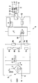
- the figure shows a schematic block diagram of a control circuit with a cooking device.
- a cooking device such as a cooker, hob or oven, has For example, electric heating elements 1,2,3, each of which one of the three phases L1, L2, L3 of the AC network and its Neutral conductor N must be connected. At least one of the heating elements 1,2,3 is controlled in the usual way by a stove timer 4, which in the figure is not shown.
- the stove timer 4 has connections 5, 6 to the phase L1 and connect the neutral conductor N. From between one of the phases and the neutral conductor N standing mains voltage is by means of a Mains capacitor Cx and a rectifier G and one Zener diode Z1 and a capacitor C1 lying parallel to this, especially electrolytic capacitor, a stabilized DC supply voltage U for a microcontroller ⁇ C Stove timer 4 derived.
- phase L1 is on Connection 5 and via the mains capacitor Cx on a primary side Pole 7 of the rectifier G.
- the other primary pole of the Rectifier G forms the connection 6.
- the Zener diode Z1 and the capacitor C1 are located in Poland 8.9 parallel.
- the microcontroller ⁇ C receives its via poles 8,9 Supply voltage.
- the stove timer 4 has an optical display device D, which in usually the time, other times and / or operating conditions displays. In addition, one controlled by the stove timer 4 cannot acoustic signal transmitter shown in detail.
- a voltage divider consisting of resistors R1, R2, R3 and one Rectifier diode D1 is between terminal 5 and pole 9 connected. Between the resistor R3 and the rectifier diode D1 is a first voltage Up corresponding to the current mains voltage tapped and placed at a first input 10 of a comparator K.
- the comparator K can be formed by a separate assembly. However, the comparator K can also be operated by the microcontroller ⁇ C itself be educated.
- the voltage divider can be made from the resistors R4 and R5 as well as the comparator K in the microcontroller ⁇ C in the form be integrated into a constant.
- the measurement of the current Main voltage corresponding to the first voltage Up can be via a internal A / D converter of the microcontroller ⁇ C.
- the comparison between the current one corresponding to the first voltage Up Mains voltage with the second voltage representing a constant Ur can then be performed using the software of the microcontroller ⁇ C become.
- the comparator K or the microcontroller ⁇ C controls via Switching element 12, for example transistor with series resistor, a relay 13, which is in series with the switching element 12, these Series connection between the secondary poles 8.9 of the Rectifier G is switched. Switch contacts 14 of the relay 13 are the heating elements 1,2,3 can be switched off.
- connection is correct, i.e. if connections 5 and 6 are on a phase L or the neutral conductor N, exists between the first Voltage Up and the second voltage Ur a certain Difference caused by line voltage fluctuations and component tolerances depends, but does not yet exceed a threshold.
- the Switch contacts 14 of the relay 13 are closed, so that the Heating elements 1 to 3 can be controlled in the usual way.
- the comparator K detects this in such a way that the relay 13 opens the contacts 14 so that the Heating elements 1,2, are not destroyed by the overvoltage can.
- the stove timer 4 is not destroyed by the surge because it is due to the stabilized DC supply voltage U.
- the optical display device D provides the user with a corresponding one Given message. This can consist, for example, of that the optical display device D displays "HELP". The User can then respond appropriately and customer service personnel notify. It is through the described control circuit ensures that the cooking appliance is damaged after incorrect connection do not occur, but at most only the cooking operation is interrupted, until the correct connection is restored.
Landscapes
- Control Of Resistance Heating (AREA)
- Electric Stoves And Ranges (AREA)
Abstract
Description
Claims (9)
- Steuerschaltung, insbesondere Herdschaltuhr, eines Kochgeräts, wobei ein Netzteil aus der Netzspannung eine stabilisierte Versorgungsgleichspannung für den Betrieb der Steuerschaltung ableitet,
dadurch gekennzeichnet, dass ein Komparator (K) eine der aktuellen Netzspannung entsprechende erste Spannung (Up) und eine der stabilisierten Versorgungsgleichspannung (U) entsprechende zweite Spannung (Ur) erfasst
und der Komparator (K) beim Abweichen der Differenz der ersten Spannung (Up) und der zweiten Spannung (Ur) von einem Schwellwert über ein Relais (13) wenigstens ein Heizelement (1,2,3) des Kochgeräts abschaltet und an einer Anzeigeeinrichtung (D) ein Signal auslöst. - Steuerschaltung nach Anspruch 1,
dadurch gekennzeichnet, dass der Schwellwert so bemessen ist, dass er bei einem Falschanschluss des Nullleiters (N) der Netzspannung überschritten ist. - Steuerschaltung nach Anspruch 1 oder 2,
dadurch gekennzeichnet, dass die aktuelle Netzspannung über einen Spannungsteiler (R1,R2,R3) mit Gleichrichter (D1) als erste Spannung (Up) an den Komparator (K) gelegt ist. - Steuerschaltung nach Anspruch 3,
dadurch gekennzeichnet, dass der Spannungsteiler mit Gleichrichter (R1,R2,D1,R3) zwischen einem Netzanschluss (5) der Steuerschaltung (4) und einem sekundärseitigen Pol (9) eines Gleichrichters (G) der Steuerschaltung (4) liegt. - Steuerschaltung nach einem der vorhergehenden Ansprüche,
dadurch gekennzeichnet, dass die stabilisierte Versorgungsgleichspannung (U) über einen Spannungsteiler (R4,R5) als zweite Spannung (Ur) an den Komparator (K) gelegt ist. - Steuerschaltung nach Anspruch 5,
dadurch gekennzeichnet, dass der Spannungsteiler (R4,R5) zwischen sekundärseitige Pole (8,9) als Gleichrichter (G), der der Erzeugung der stabilisierten Gleichspannung (U) dient, gelegt ist. - Steuerschaltung nach einem der vorhergehenden Ansprüche,
dadurch gekennzeichnet, dass der Komparator (K) von einem Mikrocontroller (µC) der Steuerschaltung (4) gebildet ist. - Steuerschaltung nach einem der vorhergehenden Ansprüche 5 bis 7,
dadurch gekennzeichnet, dass der Spannungsteiler (R4,R5) von einem Mikrocontroller (µC) der Steuerschaltung (4) gebildet ist. - Steuerschaltung nach einem der vorhergehenden Ansprüche,
dadurch gekennzeichnet, dass der Komparator (K) beim Überschreiten des Schwellwerts ein akustisches Signal auslöst.
Applications Claiming Priority (2)
| Application Number | Priority Date | Filing Date | Title |
|---|---|---|---|
| DE10214440 | 2002-03-30 | ||
| DE2002114440 DE10214440A1 (de) | 2002-03-30 | 2002-03-30 | Steuerschaltung, insbesondere Herdschaltuhr, eines Kochgeräts |
Publications (2)
| Publication Number | Publication Date |
|---|---|
| EP1349253A2 true EP1349253A2 (de) | 2003-10-01 |
| EP1349253A3 EP1349253A3 (de) | 2006-07-12 |
Family
ID=27798267
Family Applications (1)
| Application Number | Title | Priority Date | Filing Date |
|---|---|---|---|
| EP03006000A Withdrawn EP1349253A3 (de) | 2002-03-30 | 2003-03-18 | Steuerschaltung, insbesondere Herdschaltuhr, eines Kochgeräts |
Country Status (3)
| Country | Link |
|---|---|
| EP (1) | EP1349253A3 (de) |
| DE (1) | DE10214440A1 (de) |
| PL (1) | PL209302B1 (de) |
Cited By (1)
| Publication number | Priority date | Publication date | Assignee | Title |
|---|---|---|---|---|
| WO2007009852A3 (de) * | 2005-07-19 | 2007-06-14 | Bsh Bosch Siemens Hausgeraete | Verfahren und schaltungsanordnung zum ermitteln des vorliegens eines falschanschlusses eines elektrischen gerätes, insbesondere hausgerätes an einer netzwechselspannungsquelle |
Family Cites Families (1)
| Publication number | Priority date | Publication date | Assignee | Title |
|---|---|---|---|---|
| US6229682B1 (en) * | 1999-05-13 | 2001-05-08 | Ieps Electronic, Inc. | Transient voltage surge suppressor |
-
2002
- 2002-03-30 DE DE2002114440 patent/DE10214440A1/de not_active Withdrawn
-
2003
- 2003-03-18 EP EP03006000A patent/EP1349253A3/de not_active Withdrawn
- 2003-03-28 PL PL359405A patent/PL209302B1/pl unknown
Cited By (1)
| Publication number | Priority date | Publication date | Assignee | Title |
|---|---|---|---|---|
| WO2007009852A3 (de) * | 2005-07-19 | 2007-06-14 | Bsh Bosch Siemens Hausgeraete | Verfahren und schaltungsanordnung zum ermitteln des vorliegens eines falschanschlusses eines elektrischen gerätes, insbesondere hausgerätes an einer netzwechselspannungsquelle |
Also Published As
| Publication number | Publication date |
|---|---|
| DE10214440A1 (de) | 2003-10-09 |
| EP1349253A3 (de) | 2006-07-12 |
| PL209302B1 (pl) | 2011-08-31 |
| PL359405A1 (en) | 2003-10-06 |
Similar Documents
| Publication | Publication Date | Title |
|---|---|---|
| DE2822767A1 (de) | Verfahren und vorrichtung zum erwaermen eines elektromotors | |
| DE102013104629A1 (de) | Energieerzeugungseinrichtung mit funktionssicherer Potentialtrennung | |
| DE102017213357B3 (de) | Verfahren und Vorrichtung zur Erdungswiderstanderkennung in einem Ladekabel | |
| DE19548639A1 (de) | Steuermodul | |
| EP3639365A1 (de) | Einfehlersichere isolationswiderstandsbestimmung in einer photovoltaikanlage | |
| WO1995017032A1 (de) | Getaktete stromversorgung | |
| EP1349253A2 (de) | Steuerschaltung, insbesondere Herdschaltuhr, eines Kochgeräts | |
| EP2223427A1 (de) | Verfahren und vorrichtung zum betreiben eines elektrischen antriebs mit hilfe einer phasenanschnittssteuerung | |
| DE1932392A1 (de) | Steuereinrichtung fuer elektrische Belastung | |
| DE102019218919B3 (de) | Erfassen eines Schaltzustands eines elektromechanischen Schaltelements | |
| DE2941339C2 (de) | ||
| DE3427478A1 (de) | Verfahren und einrichtung zum schalten von lasten unter vermeidung hoher einschaltstromspitzen | |
| DE10214738B4 (de) | Falschanschlusserkennungsschaltung und Verfahren zur Erkennung eines Falschanschlusses | |
| DE3209939C2 (de) | Unterbrechungsfreie Stromversorgungsvorrichtung | |
| DE3728809C2 (de) | Schaltungsanordnung zum Begrenzen eines Einschaltstromes | |
| DE2743622A1 (de) | Schaltungsanordnung zum schutz elektrischer verbraucher gegen falschpolung der betriebsgleichspannung | |
| DE3631226A1 (de) | Netzanschlussschaltung eines elektrischen warmwasserspeichers | |
| DE3320013A1 (de) | Einrichtung zur phasenausfallueberwachung fuer ein drehstromsystem ohne mittelpunktsleiter | |
| DE102014213068B4 (de) | Schaltungsanordnung und Verfahren für ein Schaltnetzteil | |
| DE102018212317B4 (de) | Schaltanordnung zur Ermittlung des Zustands der Schaltelemente eines Lastpfads eines elektrischen Geräts | |
| DE102023122839A1 (de) | Stromrichter | |
| DE1914767C3 (de) | Rundsteuerempfangseinrichtung mit elektrischem Bandfilter | |
| DE10016999A1 (de) | Verfahren und Schaltungsanordnung zum Anschalten einer reaktiven Last an eine Wechselstromquelle | |
| DE358424C (de) | Metallschmelzofen mit kombinierter Induktions- und Lichtbogenheizung | |
| DE69829292T2 (de) | Vorrichtung und verfahren zum abschalten der versorgungsspannung einer last, und damit ausgerüstetes elektrisches gerät |
Legal Events
| Date | Code | Title | Description |
|---|---|---|---|
| PUAI | Public reference made under article 153(3) epc to a published international application that has entered the european phase |
Free format text: ORIGINAL CODE: 0009012 |
|
| AK | Designated contracting states |
Kind code of ref document: A2 Designated state(s): AT BE BG CH CY CZ DE DK EE ES FI FR GB GR HU IE IT LI LU MC NL PT RO SE SI SK TR |
|
| AX | Request for extension of the european patent |
Extension state: AL LT LV MK |
|
| PUAL | Search report despatched |
Free format text: ORIGINAL CODE: 0009013 |
|
| AK | Designated contracting states |
Kind code of ref document: A3 Designated state(s): AT BE BG CH CY CZ DE DK EE ES FI FR GB GR HU IE IT LI LU MC NL PT RO SE SI SK TR |
|
| AX | Request for extension of the european patent |
Extension state: AL LT LV MK |
|
| 17P | Request for examination filed |
Effective date: 20061205 |
|
| AKX | Designation fees paid |
Designated state(s): DE ES FR IT TR |
|
| RBV | Designated contracting states (corrected) |
Designated state(s): DE ES FR |
|
| GRAP | Despatch of communication of intention to grant a patent |
Free format text: ORIGINAL CODE: EPIDOSNIGR1 |
|
| RBV | Designated contracting states (corrected) |
Designated state(s): DE ES FR IT TR |
|
| STAA | Information on the status of an ep patent application or granted ep patent |
Free format text: STATUS: THE APPLICATION IS DEEMED TO BE WITHDRAWN |
|
| 18D | Application deemed to be withdrawn |
Effective date: 20111117 |