EP1349129A2 - Remote controller with impact sensor - Google Patents
Remote controller with impact sensor Download PDFInfo
- Publication number
- EP1349129A2 EP1349129A2 EP03250955A EP03250955A EP1349129A2 EP 1349129 A2 EP1349129 A2 EP 1349129A2 EP 03250955 A EP03250955 A EP 03250955A EP 03250955 A EP03250955 A EP 03250955A EP 1349129 A2 EP1349129 A2 EP 1349129A2
- Authority
- EP
- European Patent Office
- Prior art keywords
- control section
- impact
- section
- signal
- portable operation
- Prior art date
- Legal status (The legal status is an assumption and is not a legal conclusion. Google has not performed a legal analysis and makes no representation as to the accuracy of the status listed.)
- Granted
Links
Images

Classifications
-
- G—PHYSICS
- G08—SIGNALLING
- G08C—TRANSMISSION SYSTEMS FOR MEASURED VALUES, CONTROL OR SIMILAR SIGNALS
- G08C17/00—Arrangements for transmitting signals characterised by the use of a wireless electrical link
- G08C17/02—Arrangements for transmitting signals characterised by the use of a wireless electrical link using a radio link
Definitions
- This invention relates to a portable operation device provided for a controller suitable for controlling, for example, a machine tool or a robot.
- Robot controllers for machine tools have a portable operation panel which may be carried by a user.
- Robot controllers also generally have portable operation sections, such as teaching pendant, which may be carried by the user.
- portable operation sections have a display section using liquid crystal or the like, and an input operation section such as various keys and switches and have therein precision circuits.
- a portable operation section is generally operated by an operator who holds it by the hands. Accordingly, there may be a case where an operator who operates a portable operation section drops it by mistake to give it an impact.
- the conventional portable device has been designed on the assumption that it will never be subjected to an impact, as described above, it is not equipped with an impact detection device or the like. In consequence, when the conventional portable operation section is dropped by mistake, an operator only visually checks for the appearance thereof and then continues to use it as long as no damage is found from the appearance.
- a controller comprising a control section and a portable operation section which is connected with the control section through a signal line or other, e.g. radio, communication means, wherein the portable operation section has a sensor for detecting an impact applied to the portable operation section and outputting the detection signal to the control section, and the control section has means for disabling the operation of an object to be controlled by the controller when the control section is informed of the detection of an impact by the sensor.
- a controller comprising a control section and a portable operation section which is connected with the control section through a signal line or other, e.g. radio, communication means, wherein the portable operation section has a sensor for detecting an impact applied to the portable operation section and outputting the detection signal to the control section, and the control section has means for disabling the operation of an object to be controlled by the controller when the control section is informed of the detection of an impact by the sensor.
- the control section may further comprise means for automatically practicing a trouble diagnosis on the portable operation section when the control section is informed of the detection of an impact by the sensor.
- the control section may further comprise means for causing a display means to display the content of an operation for a trouble diagnosis on the portable operation section when informed of the detection of an impact by the sensor, and trouble determination means for determining whether an input signal corresponding to the operation content displayed is normally inputted and determining that a trouble has occurred when it is detected that no signal is inputted normally.
- the controller may further comprise a reset input means for inputting a reset signal to the control section, and the control section may comprise means for releasing the disabled status of the operation of an object to be controlled by the controller when the control section receives a reset input from the reset input means.
- a second aspect of the present invention relates to a controller comprising a control section and a portable operation section which is connected with the control section through a signal line or other, e.g. radio, communication means, wherein the portable operation section has a sensor for detecting an impact applied to the portable operation section and outputting the detection signal to the control section, and the control section comprises means for ignoring a signal from the portable operation section when the control section is informed of the detection of an impact by the sensor.
- a controller comprising a control section and a portable operation section which is connected with the control section through a signal line or other, e.g. radio, communication means, wherein the portable operation section has a sensor for detecting an impact applied to the portable operation section and outputting the detection signal to the control section, and the control section comprises means for ignoring a signal from the portable operation section when the control section is informed of the detection of an impact by the sensor.
- a third aspect of the invention relates to a controller comprising a control section and a portable operation section which is connected with the control section through a signal line or other, e.g. radio, communication means, wherein the portable operation section has a sensor for detecting an impact applied to the portable operation section and outputting the detection signal to the control section, and the control section comprises means for ignoring a signal from the portable operation section when the control section is informed of the detection of an impact by the sensor.
- a controller comprising a control section and a portable operation section which is connected with the control section through a signal line or other, e.g. radio, communication means, wherein the portable operation section has a sensor for detecting an impact applied to the portable operation section and outputting the detection signal to the control section, and the control section comprises means for ignoring a signal from the portable operation section when the control section is informed of the detection of an impact by the sensor.
- a fourth aspect of the present invention relates to a controller comprising a control section and a portable operation section which is connected with the control section through a signal line or other, e.g. radio, communication means, wherein the portable operation section has a sensor for detecting an impact applied to the portable operation section and outputting the detection signal to the control section, and the control section comprises means for causing a display means to display the content of an operation for a trouble diagnosis on the portable operation section when informed of the detection of an impact by the sensor, trouble determination means for determining whether an input signal corresponding to the operation content displayed is normally inputted and determining that a trouble has occurred when detected that no signal is inputted normally, and means for ignoring a signal from the portable operation section during the practicing of a trouble diagnosis and after the detection of a trouble with the trouble diagnosis.
- the portable operation section has a sensor for detecting an impact applied to the portable operation section and outputting the detection signal to the control section
- the control section comprises means for causing a display means to display the content of an operation for a trouble
- the controller may comprise reset input means for inputting a reset signal to the control section, and the control section may comprise means for canceling an ignorance of the signal from the portable operation section when a reset signal is inputted from the reset input means.
- a fifth aspect of the present invention relates to a controller comprising a control section and a portable operation section which is connected with the control section through a signal line or other, e.g. radio, communication means, wherein the portable operation section comprises a sensor for detecting an impact applied to the portable operation section and outputting the detection signal to the control section , and means for stopping the delivery of a signal to the control section when an impact is detected with the sensor.
- the portable operation section comprises a sensor for detecting an impact applied to the portable operation section and outputting the detection signal to the control section , and means for stopping the delivery of a signal to the control section when an impact is detected with the sensor.
- a controller according to the present invention may include the following preferred features:
- the sensor may detect an impact which is higher than the lowest level of an impact strength which has been set in advance.
- the sensor may comprise an impact detection storage means for storing the detected impact and output, as an impact detection, a status in which the detected impact is being stored.
- the controller may further comprise means for outputting to the sensor a signal for release of the impact detection stored in the impact detection storage means when a reset signal is inputted from the reset input means.
- a controller according to the present invention has features as described hereinbefore, though the portable operation section of the controller, carried by an operator, may be dropped by mistake and an impact applied to the portable operation section, so that a wrong signal is sent to the control section of a robot or a machine tool, this signal may be ignored so that it is not used for control of a mechanism section of a robot or machine tool,or used for stopping the mechanism section. Therefore, the mechanism section of a robot or machine tool for example, may be prevented from performing an unintended operation such as an overdrive or overshoot, thereby securing its safety.
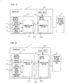
- Fig. 1 illustrates main components of a first embodiment of a controller according to the present invention.
- a mechanism section 2 of a robot or a machine tool is connected to a controller 1 through a communication line.
- the controller 1 includes a control section 21 and a portable operation section 10.
- the control section 21 controls the operation of the mechanism section 2 of the robot or the machine tool.
- the controller 1 further includes a reset input means 22 in relation to the present invention.
- the control section 21 is composed of a processor, a memory such as ROM and RAM , and an input/output interface or the like.
- the portable operation section 10 includes a display section 11 such as a liquid crystal display and an operation input section 12 such as a key and a switch and is connected with the control section 21 through a communication line 23.
- the display section 11 is used for the display or the like of various data, operation guide and a warning sent from the controller 21 and data of a value or the like inputted through the input section 12.
- the input section 12 is used for the input of various commands, setting values, operation program such as teaching programs or the like through the keys, the switches or the like included therein.
- the portable operation section 10 includes the above-described display section 11 and the input section 12, as with the case of the conventional portable operation section.
- the present invention is characterized in that this portable operation section 10 further includes an impact sensor 13.
- the impact sensor 13 of the portable operation section 10 sends an impact detection signal to the control section 21 through the communication line 23.
- This impact sensor 13 itself may be a conventionally-known one.
- Fig. 2 illustrates main components of a second embodiment of a controller according to the present invention.
- the second embodiment differs from the first embodiment in that an impact sensor 14 included in the portable operation section 10 has a status-maintaining function.
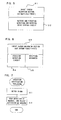
- This impact sensor 14 having the status-maintaining function also may be a conventionally-known one and has two types as shown in Figs. 5 and 6.
- One type of the impact sensor 14 having the status-maintaining function shown in Fig. 5 is composed of an impact sensor mechanism section 31 which detects an impact to automatically reset, and a vibration detecting and detected value storing circuit 32, backed up by a battery, which converts the vibration mechanically detected by the impact sensor mechanism section 31 into an electric signal to detect the vibration and store the detected value.
- the vibration detecting and detected value storing circuit 32 converts the magnitude of the vibration caused by the impact into an electric signal and stores the signal. Then, when this detected value is equal to or higher than a predetermined permissible value, the vibration detecting and detected value storing circuit 32 outputs an impact detection signal to the control section 21. Detected values stored in this vibration detecting and detected value storing circuit 32 are reset by manual operation or a signal from the control section 21.
- the other type of the impact sensor 14 having the status-maintaining function shown in Fig. 6 is an impact sensor which is composed of an impact sensor mechanism section 33 which does not automatically reset, a vibration detection circuit 34, and a reset mechanism 35.
- the impact sensor mechanism section 33 receives an impact or vibration which is equal to or higher than a predetermined permissible value, the impact sensor mechanism section 33 keeps its detection status.
- the vibration detection circuit 34 converts the detection status of the impact sensor mechanism section 33 into an electric signal to output the electric signal to the control section 21.
- the reset circuit 35 is activated by a manual operation or a signal from the control section 21 to allow the reset circuit 35 to reset the impact detection status of the sensor mechanism section 33.
- Fig. 3 illustrates main components of a third embodiment of the controller according to the present invention.
- This third embodiment differs from the first embodiment shown in Fig. 1 only in that the control section 21 and the portable operation section 10 have a radio connection therebetween.
- the portable operation section 10 and the control section 21 have communication sections 14 and 25, respectively, through which the portable operation section 10 and the control section 21 communicate through a radio link 24.
- Other configurations of the third embodiment are the same as those of the first embodiment shown in Fig. 1.
- Fig. 4 illustrates main components of a fourth embodiment of the controller according to the present invention.
- This fourth embodiment differs from the second embodiment shown in Fig. 2 only in that the portable operation section 10 and the control section 21 have the communication sections 14 and 25, respectively, through which the portable operation section 10 and the control section 21 communicate by means of the radio link 24.
- the following four operation modes are used in which: (1) a first mode in which a machine such as the machine tool and an industrial robot controlled by this controller is stopped and disabled; (2) a second mode in which a signal from the portable operation section 10 is ignored; (3) a third mode in which a signal from the portable operation section 10 is ignored or the operation of the machine is stopped to allow the machine to be in an operation-disabled status while an automatic trouble diagnosis processing is performed; and (4) a fourth mode in which an interactive trouble diagnosis processing is performed.
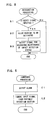
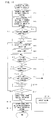
- the control section 21 performs a processing shown in Fig. 7 when receiving an impact detection signal from the impact sensors 13 or 14, outputs an alarm signal, inform of an occurrence of impact using an alert means such as a bell and a display lamp not shown (step A1), applies an emergency stop to the operation of the machine and set an impact detection flag.
- step A2 the mechanism section 2 of the robot or the machine tool will never bring about a malfunction even when an internal circuit or the like of the portable operation section 10 has a trouble due to an impact to cause an inappropriate signal to be inputted to the control section 21.
- the processor of the control section 21 performs the processing shown in Fig. 8 with a predetermined cycle to determine whether or not a reset signal has been inputted from the reset input means 22 to the control section 21 (step B1). Upon receiving the reset signal, the control section 21 reset the impact detection flag to allow the machine to be activated (step B2).
- the control section 21 sends an impact detection maintenance releasing signal to the portable operation section 10 (step B3) to cancel the maintenance of the impact/vibration detection status of the impact sensor 14. It is noted that the process at this step B3 is not required in the case where the maintenance of the impact/vibration detection status is manually cancelled and in the case of the first and third embodiments shown in Figs. 1 and 3.
- control section 21 In the case of the second mode in which the control section 21 ignores a signal from the portable operation section 10, in each of the embodiments shown in Figs. 1 to 4, the control section 21 performs a processing shown in the flowchart in Fig. 9, in addition to the processing now under execution, when receiving an impact detection signal from the impact sensor 13 or 14.
- the control section 21 outputs an alarm signal to inform of an occurrence of impact using an alert means such as a bell and a display lamp not shown (step C1) and sets an impact detection flag. Thereafter, while the impact detection flag is set, the control section 21 does not use the input signal for the control of the mechanism section 2 of the robot or the machine tool (step C2), ignoring an input signal from the portable operation section 10. As a result, the mechanism section 2 of the robot or the machine tool will never have a malfunction even when an internal circuit or the like of the portable operation section 10 has a trouble due to an impact to cause an inappropriate signal to be inputted to the control section 21.
- the control section 21 disables such a command signal.
- the mechanism section 2 of the robot or the machine tool is prevented from performing a rapid feed operation by mistake, thereby securing the safety.
- the control section 21 continues ignoring a signal from the portable operation sensor 10 until the control section 21 receives a reset signal from the reset input means 22.
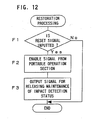
- the processor in the control section 21 executes a processing shown in Fig. 12 with a predetermined cycle to determine whether a reset signal has been inputted or not (step F1).
- the control section 21 Upon receiving the reset signal, the control section 21 resets the impact detection flag to cancel the ignorance of the signal from the portable operation section 10 and enable the signal (step F2).
- step F3 an impact detection maintenance releasing signal is sent from the control section 21 to the portable operation section 10 (step F3) in order to cancel the maintenance of the impact/vibration detection status of the impact sensor 14. It is noted that the process at this step F3 is not required in the case where the maintenance of the impact/vibration detection status is manually cancelled and in the case of the first and third embodiments shown in Figs. 1 and 3.
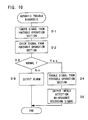
- the processor of the control section 21 When the control section 21 receives an impact detection signal, the processor of the control section 21 performs a processing shown in the flowchart shown in Fig. 10, in addition to the processing now under execution.
- the control section 21 sets an impact detection flag. While this impact detection flag is set, the control section 21 disables an input signal from the portable operation section 10 and thus does, not use this input signal for the control of the mechanism section of the machine tool or the robot (step D1).
- the control section 21 practices a conventional automatic diagnosis processing for determining whether the signal from the portable operation section 10 is a normal one or not. If determined that the signal is normal (steps D2 and D3), the control section 21 resets the impact detection flag to cancel the ignorance of the signal from the portable operation section 10 so as to enable the signal (step D4).
- the impact detection maintenance releasing signal is sent from the control section 21 to the portable operation section 10 in order to cancel the maintenance of the impact/vibration detection status of the impact sensor 14 (step D5), thereby finishing this processing.
- the control section 21 outputs an alarm signal to indicate, by an alert means such as a bell and a display lamp not shown, that the portable operation section 10 has a trouble (step D6).
- an alert means such as a bell and a display lamp not shown
- control section 21 ignores the signal from the portable operation section 10 while practicing the automatic trouble diagnosis processing.
- this mode may be modified such that operation of the mechanical section 2 is stopped when an impact is detected and then practices a trouble diagnosis processing.
- processing at step D1 in the flowchart of Fig. 10 is replaced with processing in which the operation of the mechanism section 2 is stopped and a flag for rejecting an activation of the mechanism section 2 is set to prevent the machine from being activated.
- processing at step D4 is also replaced with processing in which a flag for rejecting the activation of the mechanism section 2 is reset to allow the machine to be activated.
- Other processing are same as the corresponding ones of the third mode.
- the processor of the control section 21 When an alarm signal is issued at step D6, the processor of the control section 21 performs processing of Fig. 8 with a predetermined cycle. Upon receiving the reset signal, the control section 21 performs the processing of Fig. 8 as described above, thereby allowing the mechanism section of a machine such as a robot and machine tool to operate.
- control section 21 practices the automatic trouble diagnosis, as described above.
- fourth mode will be described with reference to a processing flowchart shown in Fig. 11 in which the control section 21 ignores the signal from the portable operation section 10 while practicing the interactive trouble diagnosis processing.
- the processor of the control section 21 when an impact detection signal is inputted from the portable operation section 10 to the control section 21, the processor of the control section 21 performs a processing of the flowchart shown in Fig. 11, in addition to the processing now under execution.
- the control section 21 sets an impact detection flag. While this flag is set, the control section 21 disables an input signal from the portable operation section 10 and thus does not use the input signal for the control of the mechanism section of the machine tool or the robot (step E1).
- control section21 displays on the display section 11 of the portable operation section 10 that an impact has occurred and that a trouble diagnosis starting command for further processing should be inputted (step E2). If an impact causes the display section and/or the display driving control circuit or the like to have a trouble, an operator will be able to recognize the occurrence of the impact from the fact that no display is performed. If the control section 21 has a display means, this display means may display various indications for an interactive trouble diagnosis.
- control section 21 waits for an input of the starting command (step E3).
- the control section 21 sets an index i to "1" (step E4) so that i-th operational indication is displayed on the display section 11 or the display means of the control section 21, thereby resetting and starting a timer (steps E5 and E6).
- the processor of the control section 21 detects whether the timer has completed time measurement or not and whether an input signal from the portable operation section 10 has changed or not (steps E7 and E8). When the timer has completed measurement of a predetermined time while the input signal from the portable operation section 10 does not change, an alarm signal is issued to inform of occurrence of a trouble with alert means such as a bell and lamp not shown (step E14).
- step E9 determines whether or not the input signal is the one based on the operation indicated at step E5 (step E9). If determined that the input signal is not the one based on the operation indicated at step E5, the procedure proceeds to step E14 to issue an alarm signal, assuming that a trouble has occurred and an inappropriate signal has been inputted.
- step E5 determines whether or not the index i exceeds the number "I" of the operational indication for the trouble diagnosis, stored in advance (step E11). If the index i does not exceed the number "I”, the procedure to step E5 to allow the display section 11 or the display means of the control section 21 to display an operational indication represented by the index i. After that, the procedure at step E6 and following steps are repeatedly executed.
- step E5 to step E11 is repeatedly executed until the index i exceeds the number I of operational indication. During this repeated execution, if the timer completes time measurement while the input signal to the control section has not changed, though an operation input is conducted according to an indication (step E9), or if any signal not corresponding to operational indication is inputted (step E9), the procedure proceeds to step E14 to output an alarm signal, as described above.
- step E11 When an operation input signal corresponding to an indication is inputted until the index i exceeds the number I of operational indication (i.e., until the result of step E11 results in "Yes"), on the other hand, the control section 21 resets the impact detection flag to enable the signal from the portable operation section 10. Thereafter, receiving an input signal for various instructions or the like from the portable operation section 10, the control section 21 performs a control in accordance with the input signal (step E12). Furthermore, when the impact sensor 14 having the status-maintaining function is used (i.e., in the case of the second and fourth embodiments shown in Figs.
- an impact detection maintenance releasing signal is sent to the portable operation section 10 to release the maintenance of the impact/vibration detection status of the impact sensor 14 (step E13), thereby completing this processing. It is noted here that the first and third embodiments shown in Figs. 1 and 3 do not store a detected impact and thus omit the processing at step E13.
- an alarm signal is issued at step E14 to ignore the signal from the portable operation section 10.
- the processor of the control section 21 performs the processing shown in Fig. 12 with a predetermined cycle.
- the control section 21 enables the signal from the portable operation section 10.
- the control section 21 sends an impact detection maintenance releasing signal to the portable operation section 10.
- control section 21 may stop the operation of the mechanism section 2 of the robot, the machine tool or the like, which is controlled by this controller 1, to practice the interactive trouble diagnosis processing.
- processing at step E1 is an operation deactivation processing in which the operation of the mechanism section 2 of a robot, machine tool or the like is stopped and the activation is prevented even when an activation command is inputted by setting a corresponding flag, in place of ignoring a signal from the portable operation section.
- the processing at step E12 is also changed such that the flag is reset to receive an activation signal for allowing the mechanism section 2 to operate.
- the processing shown in Fig. 8 is executed by the control section 21 with a predetermined cycle.
- an impact is detected by the impact sensor 14 and, when the impact detection signal is inputted to the control section 21, the control section 21 performs various processing for the detected impact.
- the portable operation section 10 may comprise therein means for rejecting and stopping a signal outputted from the portable operation section 10 to the control section 21 so as to reject an impact detection signal if it is outputted from the impact sensor 14 and stop the input of the signal to the control section 21.
- the control section 21 also issues an alarm signal or displays an indication of detection of an impact at the portable operation section.
Landscapes
- Engineering & Computer Science (AREA)
- Computer Networks & Wireless Communication (AREA)
- Physics & Mathematics (AREA)
- General Physics & Mathematics (AREA)
- Numerical Control (AREA)
- Manipulator (AREA)
- Auxiliary Devices For Machine Tools (AREA)
- Safety Devices In Control Systems (AREA)
- Selective Calling Equipment (AREA)
Abstract
Description
Claims (12)
- A controller comprising a control section and a portable operation section which is connected with said control section through a signal line or other communication means, wherein:said portable operation section has a sensor for detecting an impact applied to said portable operation section and outputting the detection signal to said control section; andsaid control section has means for disabling the operation of an object to be controlled by said controller when said control section is informed of the detection of an impact by said sensor.
- The controller according to claim 1, wherein said control section further comprises means for automatically practicing a trouble diagnosis on said portable operation section when said control section is informed of the detection of an impact by said sensor.
- The controller according to claim 1 or 2, wherein said control section further comprises:means for causing a display means to display the content of an operation for a trouble diagnosis on said portable operation section when informed of the detection of an impact by said sensor,; andtrouble determination means for determining whether an input signal corresponding to the operation content displayed is normally inputted, and determining that a trouble has occurred when it is detected that no signal is inputted normally.
- A controller comprising a control section and a portable operation section which is connected with said control section through a signal line or other communication means, wherein:said portable operation section has a sensor for detecting an impact applied to the portable operation section and outputting the detection signal to said control section; andsaid control section comprises means for ignoring a signal from said portable operation section when said control section is informed of the detection of an impact by said sensor.
- A controller comprising a control section and a portable operation section which is connected with said control section through a signal line or other communication means, wherein:said portable operation section has a sensor for detecting an impact applied to said portable operation section and outputting the detection signal to said control section; andsaid control section comprisesmeans for automatically practicing a trouble diagnosis on said portable operation section when informed of the detection of an impact by said sensor, andmeans for ignoring a signal from said portable operation section during the practicing of a trouble diagnosis with said trouble diagnosis means and after the detection of a trouble with the trouble diagnosis.
- A controller comprising a control section and a portable operation section which is connected with said control section through a signal line or other communication means, wherein:said portable operation section has a sensor for detecting an impact applied to said portable operation section and outputting the detection signal to said control section; andsaid control section comprises:means for causing a display means to display the content of an operation for a trouble diagnosis on said portable operation section when informed of the detection of an impact by said sensor,trouble determination means for determining whether an input signal corresponding to the operation content displayed is normally inputted and determining that a trouble has occurred when it is detected that no signal is inputted normally, andmeans for ignoring a signal from said portable operation section during the practicing of a trouble diagnosis and after the detection of a trouble with the trouble diagnosis.
- A controller comprising a control section and a portable operation section which is connected with said control section through a signal line or other communication means, wherein:said portable operation section comprises:a sensor for detecting an impact applied to said portable operation section and outputting the detection signal to said control section; andmeans for stopping the delivery of a signal to said control section when an impact is detected by said sensor.
- The controller according to any one of claims 1 to 7, wherein said sensor detects an impact which is higher than the lowest level of an impact strength which has been set in advance.
- The controller according to any one of claims 1 to 7, wherein said sensor comprises an impact detection storage means for storing the detected impact and outputs, as an impact detection, a status in which the detected impact is being stored.
- The controller according to any one of claims 1 to 7, wherein:said controller further comprises a reset input means for inputting a reset signal to said control section; andsaid control section comprises means for releasing a disabled status of the operation of an object to be controlled by said controller
- The controller according to any one of claims 1 to 7, wherein:said controller comprises reset input means for inputting a reset signal to said control section; andsaid control section comprises means for canceling an ignorance of the signal from said portable operation section when a reset signal is inputted from said reset input means,.
- The controller according to any one of claims 10 and 11, wherein said controller further comprises means for outputting to said sensor a signal for release of the impact detection stored in said impact detection storage means when a reset signal is inputted from said reset input means.
Priority Applications (1)
| Application Number | Priority Date | Filing Date | Title |
|---|---|---|---|
| EP08102020A EP1942476B1 (en) | 2002-03-28 | 2003-02-17 | Remote controller with impact sensor |
Applications Claiming Priority (2)
| Application Number | Priority Date | Filing Date | Title |
|---|---|---|---|
| JP2002091128 | 2002-03-28 | ||
| JP2002091128A JP3732452B2 (en) | 2002-03-28 | 2002-03-28 | Control device |
Related Child Applications (2)
| Application Number | Title | Priority Date | Filing Date |
|---|---|---|---|
| EP08102020A Division EP1942476B1 (en) | 2002-03-28 | 2003-02-17 | Remote controller with impact sensor |
| EP08102020.8 Division-Into | 2008-02-26 |
Publications (3)
| Publication Number | Publication Date |
|---|---|
| EP1349129A2 true EP1349129A2 (en) | 2003-10-01 |
| EP1349129A3 EP1349129A3 (en) | 2007-06-20 |
| EP1349129B1 EP1349129B1 (en) | 2010-11-17 |
Family
ID=27800510
Family Applications (2)
| Application Number | Title | Priority Date | Filing Date |
|---|---|---|---|
| EP08102020A Expired - Lifetime EP1942476B1 (en) | 2002-03-28 | 2003-02-17 | Remote controller with impact sensor |
| EP03250955A Expired - Lifetime EP1349129B1 (en) | 2002-03-28 | 2003-02-17 | Remote controller with impact sensor |
Family Applications Before (1)
| Application Number | Title | Priority Date | Filing Date |
|---|---|---|---|
| EP08102020A Expired - Lifetime EP1942476B1 (en) | 2002-03-28 | 2003-02-17 | Remote controller with impact sensor |
Country Status (4)
| Country | Link |
|---|---|
| US (1) | US6917837B2 (en) |
| EP (2) | EP1942476B1 (en) |
| JP (1) | JP3732452B2 (en) |
| DE (1) | DE60334952D1 (en) |
Families Citing this family (10)
| Publication number | Priority date | Publication date | Assignee | Title |
|---|---|---|---|---|
| JP2006090974A (en) * | 2004-09-27 | 2006-04-06 | Fujitsu Ltd | Impact reaction force measuring device |
| US9946230B2 (en) * | 2010-05-28 | 2018-04-17 | Ronen Apelker | Automated load control system and method |
| US9911320B2 (en) | 2013-08-02 | 2018-03-06 | Vermeer Manufacturing Company | Remote control system |
| JP6291743B2 (en) * | 2013-08-12 | 2018-03-14 | 村田機械株式会社 | Industrial machine system and transmission / reception system |
| US10589973B2 (en) | 2013-10-25 | 2020-03-17 | Ats Automation Tooling Systems Inc. | Flexible feeding and closing machine for hinged caps |
| JP6267026B2 (en) * | 2014-03-19 | 2018-01-24 | Dmg森精機株式会社 | Machine tool control system |
| US10076845B2 (en) | 2015-08-05 | 2018-09-18 | Panasonic Intellectual Property Management Co., Ltd. | Robot system, instruction input device, non-transitory computer-readable recording medium, and control method for robot system |
| JP6712784B2 (en) | 2015-12-02 | 2020-06-24 | パナソニックIpマネジメント株式会社 | Robot, robot control method, and program |
| JP6496298B2 (en) * | 2016-11-28 | 2019-04-03 | ファナック株式会社 | Portable operation panel with vibration function and vibration detection function |
| WO2023058085A1 (en) * | 2021-10-04 | 2023-04-13 | ファナック株式会社 | Numerical control device |
Family Cites Families (15)
| Publication number | Priority date | Publication date | Assignee | Title |
|---|---|---|---|---|
| JPH03190688A (en) * | 1989-12-19 | 1991-08-20 | Fanuc Ltd | Emergency stop circuit for robot |
| JPH03234198A (en) * | 1990-02-08 | 1991-10-18 | Sanyo Electric Co Ltd | Remote controller |
| JPH0555204A (en) | 1991-08-29 | 1993-03-05 | Sharp Corp | Manufacture of semiconductor device |
| JPH05241604A (en) | 1992-02-27 | 1993-09-21 | Makino Milling Mach Co Ltd | Machine operation control method |
| JPH0635521A (en) | 1992-07-17 | 1994-02-10 | Mitsubishi Heavy Ind Ltd | Nc machine tool with self-diagnosing function |
| JP3281186B2 (en) * | 1994-07-29 | 2002-05-13 | 松下電器産業株式会社 | Portable electronic equipment |
| JP3618375B2 (en) * | 1994-09-19 | 2005-02-09 | 株式会社安川電機 | Handheld controller |
| JP3331875B2 (en) * | 1996-08-28 | 2002-10-07 | 松下電器産業株式会社 | Industrial robot safety devices |
| US6186400B1 (en) * | 1998-03-20 | 2001-02-13 | Symbol Technologies, Inc. | Bar code reader with an integrated scanning component module mountable on printed circuit board |
| US6522347B1 (en) * | 2000-01-18 | 2003-02-18 | Seiko Epson Corporation | Display apparatus, portable information processing apparatus, information recording medium, and electronic apparatus |
| JP2002095064A (en) * | 2000-07-10 | 2002-03-29 | Rohm Co Ltd | Portable information device with communication function, system for controlling the portable information device, and device provided with control device for controlling the portable information device |
| JP3728655B2 (en) * | 2000-09-11 | 2005-12-21 | シャープ株式会社 | Portable terminal device and printer / scanner system |
| JP2002172543A (en) * | 2000-09-29 | 2002-06-18 | Toyoda Mach Works Ltd | Control parameter setting system and control parameter setting method for machining device |
| JP2003018538A (en) * | 2001-07-04 | 2003-01-17 | Pioneer Electronic Corp | Commercial message cut equipment, commercial message cut method, recording and reproducing equipment with commercial message cut function, and commercial cut program |
| EP1349429A3 (en) * | 2002-03-25 | 2007-10-24 | Tokyo Electron Limited | Carbon wire heating object sealing heater and fluid heating apparatus using the same heater |
-
2002
- 2002-03-28 JP JP2002091128A patent/JP3732452B2/en not_active Expired - Fee Related
-
2003
- 2003-02-17 DE DE60334952T patent/DE60334952D1/en not_active Expired - Lifetime
- 2003-02-17 EP EP08102020A patent/EP1942476B1/en not_active Expired - Lifetime
- 2003-02-17 EP EP03250955A patent/EP1349129B1/en not_active Expired - Lifetime
- 2003-02-20 US US10/368,384 patent/US6917837B2/en not_active Expired - Lifetime
Also Published As
| Publication number | Publication date |
|---|---|
| JP2003288105A (en) | 2003-10-10 |
| US20030187524A1 (en) | 2003-10-02 |
| EP1942476B1 (en) | 2012-12-12 |
| EP1349129A3 (en) | 2007-06-20 |
| EP1942476A2 (en) | 2008-07-09 |
| EP1942476A3 (en) | 2008-08-13 |
| EP1349129B1 (en) | 2010-11-17 |
| JP3732452B2 (en) | 2006-01-05 |
| DE60334952D1 (en) | 2010-12-30 |
| US6917837B2 (en) | 2005-07-12 |
Similar Documents
| Publication | Publication Date | Title |
|---|---|---|
| JP2812582B2 (en) | Industrial robot controller | |
| US7501778B2 (en) | Robot control device | |
| US7391178B2 (en) | Robot controller and robot system | |
| JP4826921B2 (en) | Automatic machine system and wireless communication method thereof | |
| US6917837B2 (en) | Controller having an impact sensor | |
| US10152043B2 (en) | Robot system | |
| WO2017208800A1 (en) | Teaching device | |
| US10395516B2 (en) | Safety instrumented control apparatus and method thereof, and safety instrumented system | |
| WO1995029809A1 (en) | Press machine | |
| KR101830444B1 (en) | Method for automatic returning of automatic tool exchanger | |
| EP1653309B1 (en) | Numerical controlled device comprising a voice generation portion | |
| JP2021104556A (en) | Balancer abnormality detection system and balancer abnormality detection method | |
| JP2005070922A (en) | Automatic machine operation permission device | |
| KR20130009316A (en) | Apparatus for controlling robot with embedded physical impact sensor and method for controlling robot using the same | |
| KR100652542B1 (en) | Device for noticing screw tightening | |
| US11767657B2 (en) | Construction machine | |
| JP4256438B2 (en) | Safety equipment for work equipment | |
| JP2529402B2 (en) | Operation control device for HA control equipment | |
| JP2009233852A (en) | Apparatus for controlling robot having stop monitoring function | |
| JP2010132388A (en) | Wireless hoisting machine and method for controlling the same | |
| JPH08110286A (en) | Operation control device of industrial vehicle | |
| KR100246219B1 (en) | System for protecting malfunction which select program for robot | |
| JPH067345Y2 (en) | Gas shutoff valve controller | |
| JPH04240030A (en) | Support device dealing with abnormality | |
| JPH01227883A (en) | Protector for pneumatic compressor |
Legal Events
| Date | Code | Title | Description |
|---|---|---|---|
| PUAI | Public reference made under article 153(3) epc to a published international application that has entered the european phase |
Free format text: ORIGINAL CODE: 0009012 |
|
| AK | Designated contracting states |
Kind code of ref document: A2 Designated state(s): AT BE BG CH CY CZ DE DK EE ES FI FR GB GR HU IE IT LI LU MC NL PT SE SI SK TR |
|
| AX | Request for extension of the european patent |
Extension state: AL LT LV MK RO |
|
| RAP1 | Party data changed (applicant data changed or rights of an application transferred) |
Owner name: FANUC LTD |
|
| PUAL | Search report despatched |
Free format text: ORIGINAL CODE: 0009013 |
|
| AK | Designated contracting states |
Kind code of ref document: A3 Designated state(s): AT BE BG CH CY CZ DE DK EE ES FI FR GB GR HU IE IT LI LU MC NL PT SE SI SK TR |
|
| AX | Request for extension of the european patent |
Extension state: AL LT LV MK RO |
|
| 17P | Request for examination filed |
Effective date: 20071017 |
|
| 17Q | First examination report despatched |
Effective date: 20071121 |
|
| AKX | Designation fees paid |
Designated state(s): DE |
|
| GRAP | Despatch of communication of intention to grant a patent |
Free format text: ORIGINAL CODE: EPIDOSNIGR1 |
|
| GRAS | Grant fee paid |
Free format text: ORIGINAL CODE: EPIDOSNIGR3 |
|
| GRAA | (expected) grant |
Free format text: ORIGINAL CODE: 0009210 |
|
| AK | Designated contracting states |
Kind code of ref document: B1 Designated state(s): DE |
|
| REF | Corresponds to: |
Ref document number: 60334952 Country of ref document: DE Date of ref document: 20101230 Kind code of ref document: P |
|
| RAP2 | Party data changed (patent owner data changed or rights of a patent transferred) |
Owner name: FANUC CORPORATION |
|
| PLBE | No opposition filed within time limit |
Free format text: ORIGINAL CODE: 0009261 |
|
| STAA | Information on the status of an ep patent application or granted ep patent |
Free format text: STATUS: NO OPPOSITION FILED WITHIN TIME LIMIT |
|
| 26N | No opposition filed |
Effective date: 20110818 |
|
| REG | Reference to a national code |
Ref country code: DE Ref legal event code: R097 Ref document number: 60334952 Country of ref document: DE Effective date: 20110818 |
|
| REG | Reference to a national code |
Ref country code: DE Ref legal event code: R082 Ref document number: 60334952 Country of ref document: DE Representative=s name: HASELTINE LAKE LLP, DE |
|
| PGFP | Annual fee paid to national office [announced via postgrant information from national office to epo] |
Ref country code: DE Payment date: 20200204 Year of fee payment: 18 |
|
| REG | Reference to a national code |
Ref country code: DE Ref legal event code: R082 Ref document number: 60334952 Country of ref document: DE Representative=s name: HL KEMPNER PATENTANWALT, RECHTSANWALT, SOLICIT, DE |
|
| REG | Reference to a national code |
Ref country code: DE Ref legal event code: R119 Ref document number: 60334952 Country of ref document: DE |
|
| PG25 | Lapsed in a contracting state [announced via postgrant information from national office to epo] |
Ref country code: DE Free format text: LAPSE BECAUSE OF NON-PAYMENT OF DUE FEES Effective date: 20210901 |