EP1348532B1 - Procédé de formage d'un secteur de lèvre d'entrée d'air et dispositif pour sa mise en oeuvre - Google Patents
Procédé de formage d'un secteur de lèvre d'entrée d'air et dispositif pour sa mise en oeuvre Download PDFInfo
- Publication number
- EP1348532B1 EP1348532B1 EP03362001A EP03362001A EP1348532B1 EP 1348532 B1 EP1348532 B1 EP 1348532B1 EP 03362001 A EP03362001 A EP 03362001A EP 03362001 A EP03362001 A EP 03362001A EP 1348532 B1 EP1348532 B1 EP 1348532B1
- Authority
- EP
- European Patent Office
- Prior art keywords
- die
- section
- sector
- extruded product
- lip
- Prior art date
- Legal status (The legal status is an assumption and is not a legal conclusion. Google has not performed a legal analysis and makes no representation as to the accuracy of the status listed.)
- Expired - Lifetime
Links
Images


Classifications
-
- B—PERFORMING OPERATIONS; TRANSPORTING
- B21—MECHANICAL METAL-WORKING WITHOUT ESSENTIALLY REMOVING MATERIAL; PUNCHING METAL
- B21C—MANUFACTURE OF METAL SHEETS, WIRE, RODS, TUBES, PROFILES OR LIKE SEMI-MANUFACTURED PRODUCTS OTHERWISE THAN BY ROLLING; AUXILIARY OPERATIONS USED IN CONNECTION WITH METAL-WORKING WITHOUT ESSENTIALLY REMOVING MATERIAL
- B21C37/00—Manufacture of metal sheets, rods, wire, tubes, profiles or like semi-manufactured products, not otherwise provided for; Manufacture of tubes of special shape
- B21C37/06—Manufacture of metal sheets, rods, wire, tubes, profiles or like semi-manufactured products, not otherwise provided for; Manufacture of tubes of special shape of tubes or metal hoses; Combined procedures for making tubes, e.g. for making multi-wall tubes
- B21C37/15—Making tubes of special shape; Making tube fittings
- B21C37/28—Making tube fittings for connecting pipes, e.g. U-pieces
-
- B—PERFORMING OPERATIONS; TRANSPORTING
- B21—MECHANICAL METAL-WORKING WITHOUT ESSENTIALLY REMOVING MATERIAL; PUNCHING METAL
- B21C—MANUFACTURE OF METAL SHEETS, WIRE, RODS, TUBES, PROFILES OR LIKE SEMI-MANUFACTURED PRODUCTS OTHERWISE THAN BY ROLLING; AUXILIARY OPERATIONS USED IN CONNECTION WITH METAL-WORKING WITHOUT ESSENTIALLY REMOVING MATERIAL
- B21C23/00—Extruding metal; Impact extrusion
- B21C23/02—Making uncoated products
- B21C23/04—Making uncoated products by direct extrusion
- B21C23/08—Making wire, rods or tubes
- B21C23/12—Extruding bent tubes or rods
-
- B—PERFORMING OPERATIONS; TRANSPORTING
- B29—WORKING OF PLASTICS; WORKING OF SUBSTANCES IN A PLASTIC STATE IN GENERAL
- B29C—SHAPING OR JOINING OF PLASTICS; SHAPING OF MATERIAL IN A PLASTIC STATE, NOT OTHERWISE PROVIDED FOR; AFTER-TREATMENT OF THE SHAPED PRODUCTS, e.g. REPAIRING
- B29C65/00—Joining or sealing of preformed parts, e.g. welding of plastics materials; Apparatus therefor
- B29C65/02—Joining or sealing of preformed parts, e.g. welding of plastics materials; Apparatus therefor by heating, with or without pressure
- B29C65/08—Joining or sealing of preformed parts, e.g. welding of plastics materials; Apparatus therefor by heating, with or without pressure using ultrasonic vibrations
-
- B—PERFORMING OPERATIONS; TRANSPORTING
- B29—WORKING OF PLASTICS; WORKING OF SUBSTANCES IN A PLASTIC STATE IN GENERAL
- B29C—SHAPING OR JOINING OF PLASTICS; SHAPING OF MATERIAL IN A PLASTIC STATE, NOT OTHERWISE PROVIDED FOR; AFTER-TREATMENT OF THE SHAPED PRODUCTS, e.g. REPAIRING
- B29C66/00—General aspects of processes or apparatus for joining preformed parts
- B29C66/40—General aspects of joining substantially flat articles, e.g. plates, sheets or web-like materials; Making flat seams in tubular or hollow articles; Joining single elements to substantially flat surfaces
- B29C66/41—Joining substantially flat articles ; Making flat seams in tubular or hollow articles
- B29C66/45—Joining of substantially the whole surface of the articles
-
- B—PERFORMING OPERATIONS; TRANSPORTING
- B29—WORKING OF PLASTICS; WORKING OF SUBSTANCES IN A PLASTIC STATE IN GENERAL
- B29C—SHAPING OR JOINING OF PLASTICS; SHAPING OF MATERIAL IN A PLASTIC STATE, NOT OTHERWISE PROVIDED FOR; AFTER-TREATMENT OF THE SHAPED PRODUCTS, e.g. REPAIRING
- B29C66/00—General aspects of processes or apparatus for joining preformed parts
- B29C66/69—General aspects of joining filaments
-
- B—PERFORMING OPERATIONS; TRANSPORTING
- B29—WORKING OF PLASTICS; WORKING OF SUBSTANCES IN A PLASTIC STATE IN GENERAL
- B29C—SHAPING OR JOINING OF PLASTICS; SHAPING OF MATERIAL IN A PLASTIC STATE, NOT OTHERWISE PROVIDED FOR; AFTER-TREATMENT OF THE SHAPED PRODUCTS, e.g. REPAIRING
- B29C66/00—General aspects of processes or apparatus for joining preformed parts
- B29C66/80—General aspects of machine operations or constructions and parts thereof
- B29C66/83—General aspects of machine operations or constructions and parts thereof characterised by the movement of the joining or pressing tools
- B29C66/836—Moving relative to and tangentially to the parts to be joined, e.g. transversely to the displacement of the parts to be joined, e.g. using a X-Y table
Definitions
- the nacelles comprise an air intake hood extended at the front by a lip having in section the shape of a U open towards the rear.
- This air inlet lip ensures the sharing of air between the part that enters the fan duct and the part that flows around the nacelle.
- Stamping using a bladder can also be used. It consists of inflating a bladder to deform and wrap around a punch in the form of a stretched sheet, the operation being carried out in several passes with intermediate heat treatments.
- the spinning it operates with the aid of cylinder tool holders to accompany the false round of the shape of the lip. If the tooling here is simple and low cost and provides good control of thicknesses, it is limited to the production of air inlets whose blank is able to be contained in a sheet. In addition, this technique leads to a significant drop in the resistance to matting involving significant monitoring and maintenance in operation.
- Hot diaphragm forming is also possible.
- the sheet to be formed is placed on a shaped punch and forced to marry the latter under the pressure of a sheet called property SPF ("Super Plastic Forming").
- the object of the invention is to overcome these various drawbacks of the known techniques by proposing a new technique for forming air intake lip sectors, which is both simple, quick to implement, low cost and easy to use. giving homogeneous parts and very good behavior.
- the subject of the invention is a method of forming U-shaped aircraft nacelle air inlet lip sectors, according to claim 1.
- the curvature of the tubular section at the exit of the die is ensured by the control of differentiated avalanches in the material passage of the die, the conservation of the curvature after exit of die being ensured either by a fixed guide device bent to the desired radius, or by an output of the profile on a turntable equipped with a shape.
- the physical characteristics of the part obtained are improved by the preferential fiber orientation of the material due to the spinning, parallel to the axis of the lip sector.
- the invention also relates to a device for implementing the method above.
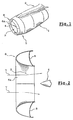
- FIG. 1 shows an aircraft turbojet engine comprising a nacelle 1 coaxially surrounding the engine itself and fixed, for example, to a wing (not shown) of the aircraft via a mast designated generally by the reference numeral 2.
- the nacelle 1 has an annular section and defines between it and the central portion of the engine an annular channel 3 of said fan.
- FIG. 4 shows the nose-shaped nose of the fan driven by the motor and which is placed at the entrance of the channel.
- the front part of the nacelle defines an air intake hood 5 whose function is to ensure the aerodynamic flow of air, on the one hand, towards the fan duct 3 and, on the other hand, to the outside of the nacelle 1.
- FIG. 2 which is a partial axial section of the cover 5, the latter is extended at the front by an air inlet lip 6 having in section the shape of a U open to the 'back. This lip ensures the sharing of air between the part 7 which enters the fan duct and the part that flows around the nacelle.
- the lip 6 is generally made up of four sectors or segments such as the sector 6a, abutting by splicing to form a complete ring.
- the object of the invention is to provide a lip sector such as sector 6a.
- the extrusion-spinning device used is conventional and is illustrated very schematically in FIG. 3 by a container 13 into which is introduced the billet 11 pressed by a pressing pusher 14, and a die 15 contiguous to the outlet face of the container 13. .
- the spun product 12 is tubular, its section being shown in FIG. 8.
- This section comprises an inverted U-shaped portion S1 in FIG. 8, corresponding to the lip to be obtained and a web S2 connecting the ends E1, E2 of the branches. from U.
- the curvature imparted to the profile 12 is made around an axis substantially orthogonal to the general plane of the web S2, that is to say the plane containing the ends E1, E2 of the sections of the section 12.
- the curvature of the spun product is obtained for example simply by adjusting the swallowing in the material passage of the die 15, that is to say by offering the material a passage section in the larger die on a branch of the U of the section than on the other, so that the spun product will warp on the side of the narrowest die.
- This warping is then channeled by a device for bending the product 12.
- Figures 4 and 5 illustrate a device adapted to this result and consists of a single fixed guide chute 16 mounted at the die outlet 15 and suitably bent.
- the length of the chute 16 depends on the length of the sectors to be obtained and, in this case, is slightly greater than a quarter of a circumference.
- FIGS. 6 and 7 illustrate another device capable of obtaining the same result and consisting of a plate 17 rotatably mounted around a vertical axis 18 and carrying a curved guide chute 19.
- the chute 19 has a curvature corresponding to that to give the spun product 12 and has a length, in this case, slightly greater than a quarter of a circumference.
- the chute 19 is curved so as to fit the product 12 on one of its flanks as shown in FIG. 7, in order to give the product the desired curvature by rotation about the axis 18.
- In 20 is represented symbolically a clamp secured to one end of the chute 19 and adapted to grip and hold in place the front end of the product 12 out of the die 15.
- In 17 ' is schematized the final position of the tray rotary 17 corresponding to a product length 12 curved a quarter of a circumference.
- FIGS. 4 to 7 the cutting means of the spun product 12 are not shown to obtain sectors of a quarter of a circumference such as that of FIG. 8.
- the sector 12 of FIG. 8 is placed in a curved two-part forming and calibration matrix, illustrated in FIG. 9.
- the matrix comprises a portion M1 having a cavity 21 receiving the portion S1 of the section of the section 12 of FIG. 8.
- the impression 21 of the matrix M1 is closed by a matrix M2 having a recess 22 corresponding to the section S2 of the profile 12, the ends E1, E2 of the branches of the U of the profile section 2 being substantially at the height of the plane of seal 23 of the two matrix portions M1, M2.
- FIG 9 which shows the profile 12 in place in the matrix before sending a hydraulic fluid under a pressure P inside the profile, there is a gap between the outer wall of the profile 12 and the cavity 21, 22.
- the role of the fluid under the pressure P which is for example of the order of 400 to 500 bar, is to press the wall of the profile 12 against the cavity.
- the volume defined in particular by the imprint 21 corresponds to the external volume of the lip sector to be increased by the elastic return of the expanded material of the profile 12.
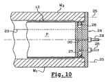
- Each end of the profile 12 is held pressed against the inner wall of the matrix M1, M2 by means of an annular seal 26 pressed by a suitable pressurized fluid conveyed in an annular groove 27 through a pipe 28, while the pressure P inside the section 12 is applied by a hydraulic fluid conveyed by a pipe 29 and a bore 30 passing through one of the flanges 24.
- the profile 12 which took the shape of the desired lip sector is cut to size, both at the two ends and at the right of the marks E1 and E2 delimiting the extreme edge of the branches of the U of the lip , over the entire length of the sector which is then exactly the shapes and dimensions sought.
- the process is of course adaptable to the realization of sectors smaller than or greater than 90 °, it is sufficient to adapt the tooling (profile bending device at the die exit and forming die calibration) accordingly.
Landscapes
- Engineering & Computer Science (AREA)
- Mechanical Engineering (AREA)
- Shaping Metal By Deep-Drawing, Or The Like (AREA)
- Extrusion Moulding Of Plastics Or The Like (AREA)
- Lining Or Joining Of Plastics Or The Like (AREA)
- Medicines That Contain Protein Lipid Enzymes And Other Medicines (AREA)
- Laminated Bodies (AREA)
Description
- La présente invention se rapporte à la fabrication de lèvres d'entrée d'air de nacelles contenant le groupe moto-propulseur, notamment un moteur à réaction, d'aéronefs.
- Les nacelles comportent un capot d'entrée d'air prolongé à l'avant par une lèvre présentant en section la forme d'un U ouvert vers l'arrière.
- Cette lèvre d'entrée d'air assure le partage de l'air entre la partie qui pénètre dans le canal de soufflante et la partie qui s'écoule autour de la nacelle.
- Elle a une forme annulaire et est constituée de plusieurs secteurs ou segments aboutés par éclissage.
- Plusieurs techniques sont utilisées pour la fabrication de tels secteurs.
- C'est ainsi que l'on peut utiliser l'emboutissage classique à froid à l'aide d'une matrice, d'un poinçon et d'un serre-flan permettant par un certain nombre de passes la mise en forme d'un flan de métal approprié, généralement un alliage à base d'aluminium, dans la matrice.
- Cette technique très connue et répandue présente l'inconvénient d'un recours à de nombreuses passes avec des traitements thermiques intermédiaires et entraîne une perte d'épaisseur conséquente du flan au cours de l'emboutissage.
- L'emboutissage à l'aide d'une vessie peut être également employé. Il consiste par gonflage d'une vessie à déformer et enrouler autour d'un poinçon en forme une tôle tendue, l'opération s'effectuant en plusieurs passes avec des traitements thermiques intermédiaires.
- Par rapport à l'emboutissage précédent, le nombre de passes est cependant réduit ainsi que la perte d'épaisseur de la tôle.
- Toutefois, la forme définitive n'est pas acquise du fait d'un retour élastique important et nécessite une mise en tension de la pièce sur un autre outillage. Les outillages ainsi mis en oeuvre sont coûteux.
- Suivant une autre technique possible, le repoussage, on opère à l'aide de porte-outils à vérin pour accompagner le faux rond de la forme de la lèvre. Si l'outillage est ici simple et de coût réduit et procure une bonne maîtrise des épaisseurs, on est limité à la réalisation d'entrées d'air dont le flan est capable d'être contenu dans une tôle. De plus, cette technique entraîne une chute importante de la tenue au matage impliquant une surveillance et une maintenance importantes en exploitation.
- Le formage par diaphragme à chaud est aussi envisageable. La tôle à former est posée sur un poinçon en forme et contrainte d'épouser ce dernier sous la pression d'une tôle dite à propriété SPF ("Super Plastic Forming").
- Une seule passe est nécessaire mais plusieurs inconvénients apparaissent liés à la maîtrise aléatoire de la forme après traitement thermique, au recours qui serait souhaitable à un outillage modélisé, et à la répétitivité incertaine du processus.
- Enfin, on pourrait recourir au formage dit "Super Plastic Forming" consistant à contraindre une tôle en matériau SPF portée à température à épouser un poinçon en forme, mais l'inconvénient majeur est qu'aucun alliage léger à propriétés SPF connu ne présente les caractéristiques requises pour la réalisation d'une lèvre d'entrée d'air.
- L'invention a pour objet de pallier à ces divers inconvénients des techniques connues en proposant une nouvelle technique de formage de secteurs de lèvre d'entrée d'air, à la fois simple, rapide à mettre en oeuvre, d'un coût réduit et donnant des pièces homogènes et de très bonne tenue.
- A cet effet, l'invention a pour objet un procédé de formage de secteurs de lèvre d'entrée d'air de nacelle d'aéronef, à section en forme de U, selon la revendication 1.
- Le courbage du profilé tubulaire en sortie de filière est assuré par la maîtrise d'avalements différenciés dans le passage matière de la filière, la conservation de la courbure après sortie de filière étant assurée soit par un dispositif fixe de guidage cintré au rayon souhaité, soit par une sortie du profilé sur un plateau rotatif équipé d'une forme.
- Un tel procédé présente de nombreux et substantiels avantages.
- Tout d'abord, les caractéristiques physiques de la pièce obtenue sont améliorées par le sens de fibrage privilégié du matériau dû au filage, parallèle à l'axe du secteur de lèvre.
- Par ailleurs, la mise en forme en une seule opération, avec un allongement homogène, maîtrisé et quasi constant sur toute la surface de la pièce apporte :
- une tenue à la ténacité et une résistance à la propagation de fissure, favorisées,
- une épaisseur constante de la pièce après formage,
- un usinage chimique facilité (pas de disparité de structure dans le matériau),
- l'homogénéité du grain de la matière garantit un aspect cosmétique constant sur toute la surface de la pièce après oxydation anodique sulfurique, alors que toutes les techniques de formage à partir d'une tôle, à l'inverse, engendrent des disparités de contraintes qui révèlent des différences d'aspect après le traitement de surface.
- Enfin, la limitation du nombre de phases pour l'obtention de la pièce permet une réduction importante du coût des pièces.
- L'invention a également pour objet un dispositif pour la mise en oeuvre du procédé ci-dessus.
- D'autres caractéristiques et avantages ressortiront de la description qui va suivre d'un mode de mise en oeuvre du procédé selon l'invention, description donnée à titre d'exemple uniquement et en regard des dessins annexés sur lesquels :
- la figure 1 est une vue schématique en perspective d'un moteur à réaction d'aéronef ;
- la figure 2 est une vue en coupe axiale de la lèvre d'entrée d'air du moteur de la figure 1 ;
- la figure 3 est une vue schématique en perspective d'une tête d'extrusion-filage en cours de filage d'un profilé tubulaire selon le procédé de l'invention ;
- la figure 4 est une vue de dessus d'un dispositif fixe de courbage du profilé en sortie de filière ;
- la figure 5 est une vue en bout suivant la flèche V du dispositif de la figure 4 ;
- la figure 6 est une vue de dessus d'un dispositif de courbage du profilé filé en sortie de filière, constitué d'un plateau rotatif à forme ;
- la figure 7 est une vue en bout suivant la flèche VII du dispositif de la figure 6 ;
- la figure 8 est une vue en perspective d'un profilé courbe issu du filage ;
- la figure 9 est une vue schématique d'une matrice de formage-calibrage du profilé courbe, et
- la figure 10 est une vue en coupe partielle d'une extrémité de la matrice de la figure 9.
- On a représenté en figure 1 un turboréacteur d'aéronef comprenant une nacelle 1 entourant coaxialement le moteur proprement dit et fixé par exemple à une aile (non représentée) de l'aéronef par l'intermédiaire d'un mât désigné d'une manière générale par la référence numérique 2.
- La nacelle 1 a une section annulaire et définit entre elle et la partie centrale du moteur un canal annulaire 3 dit de soufflante. On a représenté en 4 sur la figure le nez en forme d'ogive de la soufflante entraînée par le moteur et qui est placée à l'entrée du canal.
- La partie avant de la nacelle définit un capot d'entrée d'air 5 qui a pour fonction d'assurer l'écoulement aérodynamique de l'air, d'une part, vers le canal de soufflante 3 et, d'autre part, vers l'extérieur de la nacelle 1.
- Comme on peut l'observer sur la figure 2 qui est une coupe axiale partielle du capot 5, ce dernier se prolonge à l'avant par une lèvre d'entrée d'air 6 présentant en section la forme d'un U ouvert vers l'arrière. Cette lèvre assure le partage de l'air entre la partie 7 qui pénètre dans le canal de soufflante et la partie qui s'écoule autour de la nacelle.
- L'arrière de la lèvre 6 est fermé par une cloison interne 8.
- Comme illustré par les figures 1 et 2, la lèvre 6 est généralement constituée de quatre secteurs ou segments tels que le secteur 6a, aboutés par éclissage pour former un anneau complet.
- L'invention vise à réaliser un secteur de lèvre tel que le secteur 6a.
- A cet effet, conformément à l'invention, on va, à partir d'une billette cylindrique représentée en 11 sur la figure 3, du matériau approprié, en l'occurrence un alliage d'aluminium spécifique, élaborer par filage à la presse un profilé tubulaire courbe schématisé en 12 sur la figure 3.
- Le dispositif d'extrusion-filage utilisé est conventionnel et est illustré très schématiquement sur la figure 3 par un conteneur 13 dans lequel est introduit la billette 11 pressée par un pilon presseur 14, et une filière 15 accolée à la face de sortie du conteneur 13.
- Le filage est effectué à l'aide d'une filière 15 à noyau, à chaud, notamment par pré-chauffage de la billette 11 à la température de recuit du matériau qui est en l'occurrence entre 400 et 450 °C à titre indicatif.
- Le produit filé 12 est tubulaire, sa section étant représentée en figure 8. Cette section comprend une partie S1 en forme de U renversé sur la figure 8, correspondant à la lèvre à obtenir et un voile S2 de liaison des extrémités E1, E2 des branches du U.
- La filière 15 est conçue de façon que la section du profilé 12, qui est constante, présente un développé légèrement inférieur, de l'ordre de 2 à 3 %, au développé de la section la plus faible du secteur de lèvre à obtenir, étant entendu qu'une lèvre d'entrée d'air n'est jamais un élément torique à section constante, ni à rayon de courbure constant. C'est pourquoi le rayon de courbure conféré au profilé 12 en sortie de filage sera sensiblement égal au rayon de courbure moyen du secteur de lèvre à obtenir.
- La courbure conférée au profilé 12 est opérée autour d'un axe sensiblement orthogonal au plan général du voile S2, c'est-à-dire du plan contenant les extrémités E1, E2 des sections du profilé 12.
- La courbure du produit filé s'obtient par exemple simplement en réglant les avalements dans le passage matière de la filière 15, c'est-à-dire en offrant à la matière une section de passage dans la filière plus importante sur une branche du U de la section que sur l'autre, en sorte que le produit filé va se gauchir du côté de la filière le plus étroit.
- Ce gauchissement est ensuite canalisé par un dispositif de courbage du produit 12.
- Les figures 4 et 5 illustrent un dispositif apte à ce résultat et constitué d'une simple goulotte de guidage fixe 16 montée en sortie de filière 15 et cintrée convenablement.
- La longueur de la goulotte 16 dépend de celle des secteurs à obtenir et, dans le cas présent, est légèrement supérieure à un quart de circonférence.
- Les figures 6 et 7 illustrent un autre dispositif susceptible d'obtenir le même résultat et constitué d'un plateau 17 monté rotatif autour d'un axe vertical 18 et portant une goulotte de guidage cintrée 19. La goulotte 19 a une courbure correspondant à celle à conférer au produit filé 12 et présente une longueur, dans le cas présent, légèrement supérieure à un quart de circonférence.
- En outre, la goulotte 19 est galbée en sorte d'épouser le produit 12 sur l'un de ses flancs comme illustré par la figure 7, afin de donner au produit la courbure désirée par rotation autour de l'axe 18.
- En 20 est représentée symboliquement une pince solidaire de l'une des extrémités de la goulotte 19 et apte à saisir et maintenir en place l'extrémité frontale du produit 12 au sortir de la filière 15. En 17' est schématisée la position finale du plateau rotatif 17 correspondant à une longueur de produit 12 incurvé d'un quart de circonférence.
- Sur les figures 4 à 7, on n'a pas représenté les moyens de tronçonnage du produit filé 12 pour obtenir des secteurs d'un quart de circonférence tels que celui de la figure 8.
- Dans une deuxième étape du procédé de l'invention, le secteur 12 de la figure 8 est placé dans une matrice courbe de formage et calibrage en deux parties, illustrée en figure 9.
- La matrice comprend une partie M1 comportant une empreinte 21 recevant la partie S1 de la section du profilé 12 de la figure 8.
- L'empreinte 21 de la matrice M1 est fermée par une matrice M2 comportant une empreinte 22 correspondant à la section S2 du profilé 12, les extrémités E1, E2 des branches du U de la section du profilé 2 se trouvant sensiblement à hauteur du plan de joint 23 des deux parties de matrice M1, M2.
- Comme on peut l'observer sur la figure 9 qui montre le profilé 12 en place dans la matrice avant l'envoi d'un fluide hydraulique sous une pression P à l'intérieur du profilé, il existe un intervalle entre la paroi externe du profilé 12 et l'empreinte 21, 22. Le rôle du fluide sous la pression P qui est par exemple de l'ordre de 400 à 500 bars, est de plaquer la paroi du profilé 12 contre l'empreinte.
- Le volume défini en particulier par l'empreinte 21 correspond au volume extérieur du secteur de lèvre à obtenir augmenté du retour élastique du matériau expansé du profilé 12.
- La figure 10 représente l'une des extrémités de la matrice qui est ouverte à ses deux extrémités et reçoit un dispositif de fermeture constitué d'un flasque bouchon 24 fixé de manière amovible en 25 sur les deux parties de matrice M1, M2.
- Chaque extrémité du profilé 12 est maintenue plaquée contre la paroi interne de la matrice M1, M2 à l'aide d'un joint annulaire 26 pressé par un fluide sous pression appropriée acheminé dans une gorge annulaire 27 par une canalisation 28, cependant que la pression P à l'intérieur du profilé 12 est appliquée par un fluide hydraulique acheminé par une canalisation 29 et un perçage 30 traversant l'un des flasques 24.
- A sa sortie de la matrice, le profilé 12 qui a pris la forme du secteur de lèvre souhaité est découpé aux dimensions, à la fois aux deux extrémités et au droit des repères E1 et E2 délimitant le bord extrême des branches du U de la lèvre, sur toute la longueur du secteur qui est alors exactement aux formes et dimensions recherchées.
- Le procédé est bien entendu adaptable à la réalisation de secteurs inférieurs ou supérieurs à 90°, il suffit d'adapter les outillages (dispositif de courbage du profilé en sortie de filière et matrice de formage calibrage) en conséquence.
Claims (7)
- Procédé de formage de secteurs de lèvre d'entrée d'air (6) de nacelle d'aéronef, à section en forme de U, caractérisé en ce qu'il consiste :à élaborer, à partir d'une billette cylindrique (11) d'un matériau approprié, par filage à chaud à la presse, un profilé tubulaire (12) de section comprenant une partie (S1) en forme de U correspondant à la lèvre à obtenir et un voile (S2) de liaison des extrémités (E1, E2) des branches du U, la partie de section (S1) formée dudit profilé (12) ayant un développé inférieur de quelques pour cent au développé de la plus faible section du secteur de lèvre (6) à obtenir,- à conférer au profilé (12) au fur et à mesure de sa sortie de filière (15) une courbure dont le rayon est sensiblement égal au rayon de courbure moyen dudit secteur,- puis à former et calibrer le profilé (12) aux formes définitives du secteur par expansion hydraulique dans une matrice (M1, M2) dont l'intérieur correspond au volume extérieur dudit secteur augmenté du retour élastique du matériau à expanser,- et enfin, à découper le produit tubulaire ainsi formé pour isoler la partie à section en U constituant ledit secteur de lèvre.
- Procédé suivant la revendication 1, caractérisé en ce que le courbage du profilé tubulaire (12) en sortie de filière (15) est réalisé par la maîtrise d'avalements différenciés dans le passage matière de la filière, la conservation de la courbure après sortie de filière étant réalisée par un dispositif de guidage approprié.
- Dispositif pour la mise en oeuvre du procédé selon la revendication 1 ou 2, caractérisé en ce qu'il comprend :- un dispositif (13 à 15) d'extrusion-filage,- des moyens (16 ; 17 à 20) agencés en sortie de filière (15) pour conférer au produit filé (12) une courbure appropriée,- et une matrice de formage calibrage dudit produit filé (12).
- Dispositif suivant la revendication 3, caractérisé en ce que lesdits moyens de courbage du produit filé (12) sont constitués d'une goulotte de guidage cintrée fixe (16).
- Dispositif suivant la revendication 3, caractérisé en ce que lesdits moyens de courbage du produit filé (12) sont constitués par un plateau rotatif (17) portant une goulotte de guidage cintrée (19) dont la forme épouse le flanc du produit filé (12) et qui est munie à une extrémité d'une pince (20) de saisie de l'extrémité frontale dudit produit filé.
- Dispositif suivant l'une des revendications 3 à 5, caractérisé en ce que la matrice est en deux parties (M1, M2), l'une (M1) comportant une empreinte (21) correspondant à la partie de section en U (S1) du produit filé tubulaire (12) et l'autre (M2) comportant une empreinte (22) correspondant à la partie de section restante (S2) dudit produit (12).
- Dispositif suivant la revendication 6, caractérisé en ce que les deux parties de matrice assemblées (M1, M2) sont fermées aux extrémités par un flasque bouchon (24) de serrage des extrémités du produit filé (12) à expanser, l'un des flasques étant muni d'un conduit (30) d'introduction d'un fluide hydraulique sous pression à l'intérieur dudit produit (12).
Applications Claiming Priority (2)
| Application Number | Priority Date | Filing Date | Title |
|---|---|---|---|
| FR0203440A FR2837409B1 (fr) | 2002-03-20 | 2002-03-20 | Procede de formage d'un secteur de levre d'entree d'air, dispositif pour sa mise en oeuvre et secteur ainsi obtenu |
| FR0203680 | 2002-03-25 |
Publications (3)
| Publication Number | Publication Date |
|---|---|
| EP1348532A1 EP1348532A1 (fr) | 2003-10-01 |
| EP1348532A9 EP1348532A9 (fr) | 2006-05-24 |
| EP1348532B1 true EP1348532B1 (fr) | 2007-03-07 |
Family
ID=27772243
Family Applications (1)
| Application Number | Title | Priority Date | Filing Date |
|---|---|---|---|
| EP03362001A Expired - Lifetime EP1348532B1 (fr) | 2002-03-20 | 2003-03-17 | Procédé de formage d'un secteur de lèvre d'entrée d'air et dispositif pour sa mise en oeuvre |
Country Status (6)
| Country | Link |
|---|---|
| US (1) | US6866223B2 (fr) |
| EP (1) | EP1348532B1 (fr) |
| AT (1) | ATE355915T1 (fr) |
| CA (1) | CA2421117C (fr) |
| DE (1) | DE60312246T2 (fr) |
| FR (1) | FR2837409B1 (fr) |
Cited By (1)
| Publication number | Priority date | Publication date | Assignee | Title |
|---|---|---|---|---|
| RU2690968C1 (ru) * | 2018-07-24 | 2019-06-07 | федеральное государственное бюджетное образовательное учреждение высшего образования "Пермский национальный исследовательский политехнический университет" | Входное устройство и способ его изготовления |
Families Citing this family (6)
| Publication number | Priority date | Publication date | Assignee | Title |
|---|---|---|---|---|
| DE10209481C1 (de) * | 2002-03-05 | 2003-12-04 | Wkw Erbsloeh Automotive Gmbh | Verfahren zum Ablängen eines Strangpressprofils |
| JP4418168B2 (ja) * | 2003-05-14 | 2010-02-17 | 本田技研工業株式会社 | 楕円形環体の製造方法 |
| DE102006031330B4 (de) * | 2005-07-14 | 2014-03-20 | Goodrich Corp. | Für Eis empfänglicher Abschnitt eines Flugzeugs, insbesondere Flugtriebwerk- Zelleneinlasslippe, umfassend ein Eisschutzsystem, Flugtriebwerk mit einer solchen Einlasslippe sowie ein Verfahren zum Schutz einer solchen Einlasslippe vor Vereisung |
| CN100421873C (zh) * | 2006-04-17 | 2008-10-01 | 江苏华阳金属管件有限公司 | 冷挤压成型管道配件的方法 |
| US8757540B2 (en) * | 2008-06-30 | 2014-06-24 | Pratt & Whitney Canada Corp. | Nacelle inlet lip |
| CN109731981A (zh) * | 2019-01-04 | 2019-05-10 | 西南交通大学 | 材料的塑性变形设备 |
Family Cites Families (9)
| Publication number | Priority date | Publication date | Assignee | Title |
|---|---|---|---|---|
| US2133874A (en) * | 1936-08-06 | 1938-10-18 | Sparks Processes Inc | Method and apparatus for extruding metal strips |
| US2591062A (en) * | 1948-03-03 | 1952-04-01 | Ibm | Extrusion device and process |
| US4458863A (en) * | 1980-03-10 | 1984-07-10 | The Boeing Company | Strut supported inlet |
| JPS58199626A (ja) * | 1982-05-14 | 1983-11-21 | Okuda Kinzoku Kk | エルボ |
| FI71243C (fi) * | 1984-06-27 | 1986-12-19 | Outokumpu Oy | Foerfarande och anordning foer framstaellning av koppar- ellerkopparlegeringsroer bildade kokiller foer straenggjutning smskiner foer ett aemne |
| NL194783C (nl) * | 1992-01-24 | 2003-03-04 | Alcoa Nederland Bv | Werkwijze voor het extruderen van profiel in gebogen vorm. |
| NL9200138A (nl) * | 1992-01-24 | 1993-08-16 | Reynolds Aluminium Bv | Extrusiewerkwijze en extrusieinrichting. |
| US5600990A (en) * | 1995-06-27 | 1997-02-11 | P.M.A.C., Ltd. | Metal extrusion die stack and method |
| FR2787509B1 (fr) * | 1998-12-21 | 2001-03-30 | Aerospatiale | Structure d'entree d'air pour moteur d'aeronef |
-
2002
- 2002-03-20 FR FR0203440A patent/FR2837409B1/fr not_active Expired - Fee Related
-
2003
- 2003-03-12 CA CA2421117A patent/CA2421117C/fr not_active Expired - Fee Related
- 2003-03-17 EP EP03362001A patent/EP1348532B1/fr not_active Expired - Lifetime
- 2003-03-17 DE DE60312246T patent/DE60312246T2/de not_active Expired - Lifetime
- 2003-03-17 AT AT03362001T patent/ATE355915T1/de not_active IP Right Cessation
- 2003-03-19 US US10/390,908 patent/US6866223B2/en not_active Expired - Lifetime
Cited By (1)
| Publication number | Priority date | Publication date | Assignee | Title |
|---|---|---|---|---|
| RU2690968C1 (ru) * | 2018-07-24 | 2019-06-07 | федеральное государственное бюджетное образовательное учреждение высшего образования "Пермский национальный исследовательский политехнический университет" | Входное устройство и способ его изготовления |
Also Published As
| Publication number | Publication date |
|---|---|
| FR2837409A1 (fr) | 2003-09-26 |
| US20030178529A1 (en) | 2003-09-25 |
| EP1348532A1 (fr) | 2003-10-01 |
| DE60312246D1 (de) | 2007-04-19 |
| EP1348532A9 (fr) | 2006-05-24 |
| CA2421117A1 (fr) | 2003-09-20 |
| CA2421117C (fr) | 2011-06-21 |
| FR2837409B1 (fr) | 2004-06-04 |
| ATE355915T1 (de) | 2007-03-15 |
| DE60312246T2 (de) | 2007-11-08 |
| US6866223B2 (en) | 2005-03-15 |
Similar Documents
| Publication | Publication Date | Title |
|---|---|---|
| EP0034549B1 (fr) | Procédé de dudgeonnage et outil susceptible d'être utilisé pour la mise en oeuvre de ce procédé | |
| EP1346781A1 (fr) | Procédé de formage d'un secteur de lèvre d'entrée d'air, dispositif pour sa mise en oeuvre et secteur ainsi obtenu | |
| EP0381556B1 (fr) | Procédé de fabrication d'un axe creux à renflements internes de révolution; axe obtenu par ce procédé | |
| FR2544638A1 (fr) | Procede de production d'un tube en acier plaque | |
| EP0072064A1 (fr) | Procédé et appareillage pour la fabrication de tuyaux en matière plastique orientée moléculairement | |
| FR2750913A1 (fr) | Procede de percage d'une jante a rayon, jante percee selon le procede, insert adapte pour equiper la jante, et roue notamment de cycle | |
| CA2698240C (fr) | Procede de fabrication de tubes par soudage | |
| CA2421117C (fr) | Procede de formage d'un secteur de levre d'entree d'air, dispositif pour sa mise en oeuvre et secteur ainsi obtenu | |
| FR2766534A1 (fr) | Ensemble combine forme d'un cylindre de frein de service et d'un cylindre de frein a ressort accumulateur | |
| EP0048701B1 (fr) | Procédé de fabrication d'éléments de raccorderie pour tubes | |
| FR2536680A1 (fr) | Procede de fabrication d'un raccord tubulaire en forme de te | |
| EP0841111A1 (fr) | Procédé d'obtention de cannelures sur un arbre | |
| EP1930146A1 (fr) | Rayon en matière composite pour une roue à rayons | |
| CA2207828C (fr) | Procede de fabrication d'une aube creuse de turbomachine comportant un decollement apres soudage | |
| CH622857A5 (fr) | ||
| FR2728013A1 (fr) | Voiture de pale soudee par diffusion et son procede de fabrication | |
| EP1649990B1 (fr) | Procédé de fabrication d'une pièce peinte en matière plastique pour l'industrie automobile, comportant un orifice ayant une embouchure rayonnée et l'utilisation du procédé | |
| FR2544806A1 (fr) | Procede d'assemblage de deux pieces de revolution coaxiales, de meme diametre | |
| EP1762372B1 (fr) | Dispositif pour la réalisation d'une lentille optique en matiére synthétique polymérisable | |
| FR2534159A1 (fr) | Procede de fabrication de pieces cylindriques, notamment de pieces creuses, et machine pour sa mise en oeuvre | |
| FR2550475A1 (fr) | Procede d'extrusion a chaud de tubes en acier et alliages speciaux, et dispositif de mise en oeuvre | |
| WO2005110720A1 (fr) | Procede de soudage pour contenant | |
| FR2846580A1 (fr) | Procede de fabrication d'une enveloppe de silencieux ou de catalyseur | |
| CH293510A (fr) | Dispositif pour la fabrication, sur machine à extrusion, d'un élément en matiére plastique. | |
| FR2475947A1 (fr) | Procede de production d'articles creux par emboutissage profond, presse pour la mise en oeuvre de ce procede et articles creux obtenus |
Legal Events
| Date | Code | Title | Description |
|---|---|---|---|
| PUAI | Public reference made under article 153(3) epc to a published international application that has entered the european phase |
Free format text: ORIGINAL CODE: 0009012 |
|
| AK | Designated contracting states |
Kind code of ref document: A1 Designated state(s): AT BE BG CH CY CZ DE DK EE ES FI FR GB GR HU IE IT LI LU MC NL PT RO SE SI SK TR |
|
| AX | Request for extension of the european patent |
Extension state: AL LT LV MK |
|
| 17P | Request for examination filed |
Effective date: 20040228 |
|
| AKX | Designation fees paid |
Designated state(s): AT BE BG CH CY CZ DE DK EE ES FI FR GB GR HU IE IT LI LU MC NL PT RO SE SI SK TR |
|
| RIC1 | Information provided on ipc code assigned before grant |
Ipc: 7B 21C 23/12 A Ipc: 7B 21C 37/28 B Ipc: 7F 02C 7/045 B |
|
| RIN1 | Information on inventor provided before grant (corrected) |
Inventor name: CHEVALIER, LUCIEN |
|
| RTI1 | Title (correction) |
Free format text: METHOD OF FORMING AN AIR INTAKE LIP SECTOR, DEVICE FOR APPLYING THIS METHOD AND SECTOR THUS OBTAINED |
|
| GRAP | Despatch of communication of intention to grant a patent |
Free format text: ORIGINAL CODE: EPIDOSNIGR1 |
|
| RTI1 | Title (correction) |
Free format text: METHOD OF FORMING AN AIR INTAKE LIP SECTOR AND DEVICE FOR APPLYING THIS METHOD |
|
| GRAS | Grant fee paid |
Free format text: ORIGINAL CODE: EPIDOSNIGR3 |
|
| GRAA | (expected) grant |
Free format text: ORIGINAL CODE: 0009210 |
|
| AK | Designated contracting states |
Kind code of ref document: B1 Designated state(s): AT BE BG CH CY CZ DE DK EE ES FI FR GB GR HU IE IT LI LU MC NL PT RO SE SI SK TR |
|
| PG25 | Lapsed in a contracting state [announced via postgrant information from national office to epo] |
Ref country code: IE Free format text: LAPSE BECAUSE OF FAILURE TO SUBMIT A TRANSLATION OF THE DESCRIPTION OR TO PAY THE FEE WITHIN THE PRESCRIBED TIME-LIMIT Effective date: 20070307 Ref country code: FI Free format text: LAPSE BECAUSE OF FAILURE TO SUBMIT A TRANSLATION OF THE DESCRIPTION OR TO PAY THE FEE WITHIN THE PRESCRIBED TIME-LIMIT Effective date: 20070307 Ref country code: NL Free format text: LAPSE BECAUSE OF FAILURE TO SUBMIT A TRANSLATION OF THE DESCRIPTION OR TO PAY THE FEE WITHIN THE PRESCRIBED TIME-LIMIT Effective date: 20070307 Ref country code: SI Free format text: LAPSE BECAUSE OF FAILURE TO SUBMIT A TRANSLATION OF THE DESCRIPTION OR TO PAY THE FEE WITHIN THE PRESCRIBED TIME-LIMIT Effective date: 20070307 Ref country code: AT Free format text: LAPSE BECAUSE OF FAILURE TO SUBMIT A TRANSLATION OF THE DESCRIPTION OR TO PAY THE FEE WITHIN THE PRESCRIBED TIME-LIMIT Effective date: 20070307 |
|
| REG | Reference to a national code |
Ref country code: GB Ref legal event code: FG4D Free format text: NOT ENGLISH |
|
| PGFP | Annual fee paid to national office [announced via postgrant information from national office to epo] |
Ref country code: ES Payment date: 20070327 Year of fee payment: 5 |
|
| REG | Reference to a national code |
Ref country code: CH Ref legal event code: EP |
|
| REF | Corresponds to: |
Ref document number: 60312246 Country of ref document: DE Date of ref document: 20070419 Kind code of ref document: P |
|
| REG | Reference to a national code |
Ref country code: IE Ref legal event code: FG4D Free format text: LANGUAGE OF EP DOCUMENT: FRENCH |
|
| PG25 | Lapsed in a contracting state [announced via postgrant information from national office to epo] |
Ref country code: ES Free format text: LAPSE BECAUSE OF FAILURE TO SUBMIT A TRANSLATION OF THE DESCRIPTION OR TO PAY THE FEE WITHIN THE PRESCRIBED TIME-LIMIT Effective date: 20070618 |
|
| REG | Reference to a national code |
Ref country code: SE Ref legal event code: TRGR |
|
| GBT | Gb: translation of ep patent filed (gb section 77(6)(a)/1977) |
Effective date: 20070611 |
|
| PG25 | Lapsed in a contracting state [announced via postgrant information from national office to epo] |
Ref country code: PT Free format text: LAPSE BECAUSE OF FAILURE TO SUBMIT A TRANSLATION OF THE DESCRIPTION OR TO PAY THE FEE WITHIN THE PRESCRIBED TIME-LIMIT Effective date: 20070807 |
|
| NLV1 | Nl: lapsed or annulled due to failure to fulfill the requirements of art. 29p and 29m of the patents act | ||
| REG | Reference to a national code |
Ref country code: IE Ref legal event code: FD4D |
|
| REG | Reference to a national code |
Ref country code: CH Ref legal event code: PL |
|
| PG25 | Lapsed in a contracting state [announced via postgrant information from national office to epo] |
Ref country code: SK Free format text: LAPSE BECAUSE OF FAILURE TO SUBMIT A TRANSLATION OF THE DESCRIPTION OR TO PAY THE FEE WITHIN THE PRESCRIBED TIME-LIMIT Effective date: 20070307 |
|
| BERE | Be: lapsed |
Owner name: AIRBUS FRANCE Effective date: 20070331 |
|
| PG25 | Lapsed in a contracting state [announced via postgrant information from national office to epo] |
Ref country code: BE Free format text: LAPSE BECAUSE OF NON-PAYMENT OF DUE FEES Effective date: 20070331 Ref country code: CZ Free format text: LAPSE BECAUSE OF FAILURE TO SUBMIT A TRANSLATION OF THE DESCRIPTION OR TO PAY THE FEE WITHIN THE PRESCRIBED TIME-LIMIT Effective date: 20070307 Ref country code: RO Free format text: LAPSE BECAUSE OF FAILURE TO SUBMIT A TRANSLATION OF THE DESCRIPTION OR TO PAY THE FEE WITHIN THE PRESCRIBED TIME-LIMIT Effective date: 20070307 |
|
| PLBE | No opposition filed within time limit |
Free format text: ORIGINAL CODE: 0009261 |
|
| STAA | Information on the status of an ep patent application or granted ep patent |
Free format text: STATUS: NO OPPOSITION FILED WITHIN TIME LIMIT |
|
| PG25 | Lapsed in a contracting state [announced via postgrant information from national office to epo] |
Ref country code: MC Free format text: LAPSE BECAUSE OF NON-PAYMENT OF DUE FEES Effective date: 20070331 Ref country code: DK Free format text: LAPSE BECAUSE OF FAILURE TO SUBMIT A TRANSLATION OF THE DESCRIPTION OR TO PAY THE FEE WITHIN THE PRESCRIBED TIME-LIMIT Effective date: 20070307 |
|
| 26N | No opposition filed |
Effective date: 20071210 |
|
| PG25 | Lapsed in a contracting state [announced via postgrant information from national office to epo] |
Ref country code: CH Free format text: LAPSE BECAUSE OF NON-PAYMENT OF DUE FEES Effective date: 20070331 Ref country code: LI Free format text: LAPSE BECAUSE OF NON-PAYMENT OF DUE FEES Effective date: 20070331 |
|
| PG25 | Lapsed in a contracting state [announced via postgrant information from national office to epo] |
Ref country code: GR Free format text: LAPSE BECAUSE OF FAILURE TO SUBMIT A TRANSLATION OF THE DESCRIPTION OR TO PAY THE FEE WITHIN THE PRESCRIBED TIME-LIMIT Effective date: 20070608 |
|
| PG25 | Lapsed in a contracting state [announced via postgrant information from national office to epo] |
Ref country code: EE Free format text: LAPSE BECAUSE OF FAILURE TO SUBMIT A TRANSLATION OF THE DESCRIPTION OR TO PAY THE FEE WITHIN THE PRESCRIBED TIME-LIMIT Effective date: 20070307 |
|
| PG25 | Lapsed in a contracting state [announced via postgrant information from national office to epo] |
Ref country code: CY Free format text: LAPSE BECAUSE OF FAILURE TO SUBMIT A TRANSLATION OF THE DESCRIPTION OR TO PAY THE FEE WITHIN THE PRESCRIBED TIME-LIMIT Effective date: 20070307 |
|
| PG25 | Lapsed in a contracting state [announced via postgrant information from national office to epo] |
Ref country code: LU Free format text: LAPSE BECAUSE OF NON-PAYMENT OF DUE FEES Effective date: 20070317 Ref country code: BG Free format text: LAPSE BECAUSE OF FAILURE TO SUBMIT A TRANSLATION OF THE DESCRIPTION OR TO PAY THE FEE WITHIN THE PRESCRIBED TIME-LIMIT Effective date: 20070607 |
|
| PG25 | Lapsed in a contracting state [announced via postgrant information from national office to epo] |
Ref country code: HU Free format text: LAPSE BECAUSE OF FAILURE TO SUBMIT A TRANSLATION OF THE DESCRIPTION OR TO PAY THE FEE WITHIN THE PRESCRIBED TIME-LIMIT Effective date: 20070908 Ref country code: TR Free format text: LAPSE BECAUSE OF FAILURE TO SUBMIT A TRANSLATION OF THE DESCRIPTION OR TO PAY THE FEE WITHIN THE PRESCRIBED TIME-LIMIT Effective date: 20070307 |
|
| REG | Reference to a national code |
Ref country code: GB Ref legal event code: 732E Free format text: REGISTERED BETWEEN 20110721 AND 20110727 |
|
| REG | Reference to a national code |
Ref country code: FR Ref legal event code: TP Owner name: AIRBUS HOLDING, FR Effective date: 20110913 Ref country code: FR Ref legal event code: CJ Effective date: 20110916 Ref country code: FR Ref legal event code: CD Owner name: AIRBUS HOLDING, FR Effective date: 20110916 Ref country code: FR Ref legal event code: CA Effective date: 20110916 |
|
| REG | Reference to a national code |
Ref country code: DE Ref legal event code: R082 Ref document number: 60312246 Country of ref document: DE Representative=s name: SPARING - ROEHL - HENSELER, DE |
|
| REG | Reference to a national code |
Ref country code: DE Ref legal event code: R081 Ref document number: 60312246 Country of ref document: DE Owner name: AIRBUS OPERATIONS SAS, FR Free format text: FORMER OWNER: AIRBUS FRANCE, TOULOUSE, FR Effective date: 20120326 Ref country code: DE Ref legal event code: R082 Ref document number: 60312246 Country of ref document: DE Representative=s name: SPARING - ROEHL - HENSELER, DE Effective date: 20120326 |
|
| PGFP | Annual fee paid to national office [announced via postgrant information from national office to epo] |
Ref country code: SE Payment date: 20120322 Year of fee payment: 10 |
|
| PGFP | Annual fee paid to national office [announced via postgrant information from national office to epo] |
Ref country code: IT Payment date: 20120328 Year of fee payment: 10 |
|
| REG | Reference to a national code |
Ref country code: SE Ref legal event code: EUG |
|
| PG25 | Lapsed in a contracting state [announced via postgrant information from national office to epo] |
Ref country code: SE Free format text: LAPSE BECAUSE OF NON-PAYMENT OF DUE FEES Effective date: 20130318 |
|
| PG25 | Lapsed in a contracting state [announced via postgrant information from national office to epo] |
Ref country code: IT Free format text: LAPSE BECAUSE OF NON-PAYMENT OF DUE FEES Effective date: 20130317 |
|
| PGFP | Annual fee paid to national office [announced via postgrant information from national office to epo] |
Ref country code: DE Payment date: 20150320 Year of fee payment: 13 |
|
| REG | Reference to a national code |
Ref country code: FR Ref legal event code: PLFP Year of fee payment: 14 |
|
| REG | Reference to a national code |
Ref country code: DE Ref legal event code: R119 Ref document number: 60312246 Country of ref document: DE |
|
| PG25 | Lapsed in a contracting state [announced via postgrant information from national office to epo] |
Ref country code: DE Free format text: LAPSE BECAUSE OF NON-PAYMENT OF DUE FEES Effective date: 20161001 |
|
| REG | Reference to a national code |
Ref country code: FR Ref legal event code: PLFP Year of fee payment: 15 |
|
| REG | Reference to a national code |
Ref country code: FR Ref legal event code: PLFP Year of fee payment: 16 |
|
| PGFP | Annual fee paid to national office [announced via postgrant information from national office to epo] |
Ref country code: GB Payment date: 20200323 Year of fee payment: 18 |
|
| PGFP | Annual fee paid to national office [announced via postgrant information from national office to epo] |
Ref country code: FR Payment date: 20200319 Year of fee payment: 18 |
|
| GBPC | Gb: european patent ceased through non-payment of renewal fee |
Effective date: 20210317 |
|
| PG25 | Lapsed in a contracting state [announced via postgrant information from national office to epo] |
Ref country code: GB Free format text: LAPSE BECAUSE OF NON-PAYMENT OF DUE FEES Effective date: 20210317 Ref country code: FR Free format text: LAPSE BECAUSE OF NON-PAYMENT OF DUE FEES Effective date: 20210331 |