EP1348384A2 - Instrument médical pour fraiser une courbe dans un os - Google Patents
Instrument médical pour fraiser une courbe dans un os Download PDFInfo
- Publication number
- EP1348384A2 EP1348384A2 EP03252009A EP03252009A EP1348384A2 EP 1348384 A2 EP1348384 A2 EP 1348384A2 EP 03252009 A EP03252009 A EP 03252009A EP 03252009 A EP03252009 A EP 03252009A EP 1348384 A2 EP1348384 A2 EP 1348384A2
- Authority
- EP
- European Patent Office
- Prior art keywords
- reamer
- bone
- segment
- cutting
- segments
- Prior art date
- Legal status (The legal status is an assumption and is not a legal conclusion. Google has not performed a legal analysis and makes no representation as to the accuracy of the status listed.)
- Withdrawn
Links
- 210000000988 bone and bone Anatomy 0.000 title claims abstract description 88
- 238000003801 milling Methods 0.000 title claims abstract description 63
- 230000000717 retained effect Effects 0.000 claims abstract description 4
- 230000008878 coupling Effects 0.000 claims description 54
- 238000010168 coupling process Methods 0.000 claims description 54
- 238000005859 coupling reaction Methods 0.000 claims description 54
- 238000004891 communication Methods 0.000 claims description 7
- 230000000295 complement effect Effects 0.000 claims description 2
- 238000006073 displacement reaction Methods 0.000 claims 1
- 210000000689 upper leg Anatomy 0.000 description 14
- 239000007943 implant Substances 0.000 description 9
- 238000002360 preparation method Methods 0.000 description 9
- 238000002513 implantation Methods 0.000 description 7
- 238000000034 method Methods 0.000 description 7
- 238000002271 resection Methods 0.000 description 3
- 208000010392 Bone Fractures Diseases 0.000 description 2
- 206010017076 Fracture Diseases 0.000 description 2
- 238000003780 insertion Methods 0.000 description 2
- 230000037431 insertion Effects 0.000 description 2
- 230000007774 longterm Effects 0.000 description 2
- 239000000463 material Substances 0.000 description 2
- 229910001220 stainless steel Inorganic materials 0.000 description 2
- 239000010935 stainless steel Substances 0.000 description 2
- 230000036346 tooth eruption Effects 0.000 description 2
- 210000003484 anatomy Anatomy 0.000 description 1
- 230000004323 axial length Effects 0.000 description 1
- 230000007423 decrease Effects 0.000 description 1
- 230000001419 dependent effect Effects 0.000 description 1
- 238000005553 drilling Methods 0.000 description 1
- 239000007787 solid Substances 0.000 description 1
- 238000012546 transfer Methods 0.000 description 1
Images


Classifications
-
- A—HUMAN NECESSITIES
- A61—MEDICAL OR VETERINARY SCIENCE; HYGIENE
- A61B—DIAGNOSIS; SURGERY; IDENTIFICATION
- A61B17/00—Surgical instruments, devices or methods, e.g. tourniquets
- A61B17/16—Bone cutting, breaking or removal means other than saws, e.g. Osteoclasts; Drills or chisels for bones; Trepans
- A61B17/1662—Bone cutting, breaking or removal means other than saws, e.g. Osteoclasts; Drills or chisels for bones; Trepans for particular parts of the body
- A61B17/1664—Bone cutting, breaking or removal means other than saws, e.g. Osteoclasts; Drills or chisels for bones; Trepans for particular parts of the body for the hip
- A61B17/1668—Bone cutting, breaking or removal means other than saws, e.g. Osteoclasts; Drills or chisels for bones; Trepans for particular parts of the body for the hip for the upper femur
-
- A—HUMAN NECESSITIES
- A61—MEDICAL OR VETERINARY SCIENCE; HYGIENE
- A61B—DIAGNOSIS; SURGERY; IDENTIFICATION
- A61B17/00—Surgical instruments, devices or methods, e.g. tourniquets
- A61B17/16—Bone cutting, breaking or removal means other than saws, e.g. Osteoclasts; Drills or chisels for bones; Trepans
- A61B17/1613—Component parts
- A61B17/1631—Special drive shafts, e.g. flexible shafts
-
- A—HUMAN NECESSITIES
- A61—MEDICAL OR VETERINARY SCIENCE; HYGIENE
- A61B—DIAGNOSIS; SURGERY; IDENTIFICATION
- A61B17/00—Surgical instruments, devices or methods, e.g. tourniquets
- A61B17/16—Bone cutting, breaking or removal means other than saws, e.g. Osteoclasts; Drills or chisels for bones; Trepans
- A61B17/164—Bone cutting, breaking or removal means other than saws, e.g. Osteoclasts; Drills or chisels for bones; Trepans intramedullary
Definitions
- the present invention relates to medical instruments and procedures and, more particularly, to a medical instrument capable of milling bone along a curve, especially in preparation for implantation of a prosthesis.
- Preparation of the bone canal for implantation of a prosthetic stem is presently prepared by drilling a resected end of a bone, such as a femur, and then preparing an area adjacent the drilled hole to provide a seat for the prosthetic stem.
- Preparation of the area adjacent the drilled hole may be accomplished by broaching or by milling.
- milling has been identified as an extremely precise method of bone preparation in many orthopaedic applications as compared to broaching. Bone milling is currently thus the preferred method of bone preparation.
- the concept is that a precise bone envelope reduces the gaps between the implant (i.e. prosthesis or prosthetic component) and the bone, thereby improving the initial and long-term bone ingrowth/fixation.
- a critical limitation of milling systems today is that they use straight reamers to remove bone.
- Straight reamers limit the geometry that can be created in the bone and thus the external geometry of the corresponding implant.
- a typical milling frame is disclosed in US-5540694. This milling frame uses a straight reamer that is useable for various geometries. For example, the anatomy of the medial endosteum of the femur can be described as a curve. Many implant designs thus employ a medial curve to load this region. It is therefore desirable to have a device that can precisely mill the bone to allow for the medial curve as such would improve the accuracy of the bone preparation and thus the bone fixation.
- One way of preparing the bone along a curved path is to use a series of broaches.
- Broaches however, have serious limitations.
- One such limitation is the risk of fracture during broaching. Since broaching is done by pounding the broach into the bone, the bone tends to fracture.
- medullary canal reamers are used to enlarge the medullary canal of bones in preparation for the insertion of a prosthetic component, such as a total hip prosthesis.
- a prosthetic component such as a total hip prosthesis.
- One such device in the form of a flexible shaft for a reamer, is disclosed in US-6053 922.
- the disclosed shaft comprises a solid element with a longitudinal bore the entire length thereof, and a slot formed thereon that extends spirally around the shaft either continuously or segmentally.
- a problem with this flexible shaft is that it is only concerned with the shaft portion and not the cutting portion of the reamer. As such, the cutting geometry associated with the reamer and the flexible shaft is no different than other embodiment of reamers.
- known reamers have fixed input shafts for connecting to and/or receiving motive (i.e. rotary) power.
- motive i.e. rotary
- the prior reamers are able to accept rotary input power with respect to only one direction. Typically, this direction is at 0° (i.e. "straight on”). Therefore, not only is the input power direction restricted, but this, in turn, restricts the angle at which the reamer may be used on a patient.
- a bone milling device as desired above that also is able to accept input rotary power from various angular orientations and/or allows bone milling device to be positioned at various angular orientations relative to the input rotary power.
- the subject invention is a bone milling apparatus that is configured to mill bone along a curve.
- the subject invention also provides a procedure of use for the bone milling apparatus.
- the bone milling apparatus comprises a frame, a flexible reamer, and a guide for the flexible reamer, and an input coupled to the flexible reamer that is adapted to be coupled to a rotary motion input.
- the guide has a predetermined curve.
- the flexible reamer includes a plurality of cutters that are linked to each other and carried by the guide so as to be rotatable thereon.
- the input allows the flexible reamer to be positioned in two or more angular orientations relative to the rotary motion input.
- the subject invention provides a reamer for milling bone.
- the reamer includes a plurality of individual, interlocking segments, with each segment including a cutting surface, and a multi-orientation input coupling in communication with a first one of said plurality of segments and configured to be coupled to a source of rotary motion.
- the multi-orientation input coupling is configured to transmit rotary motion from the source of rotary motion to the plurality of segments.
- the subject invention provides a reamer for milling bone.
- the reamer includes a first segment, a last segment configured to be rotatably received in a milling frame, a plurality of intermediate segments defining a first end that is linked to the first segment and a second end that is linked to the last segment with each intermediate segment having a first cutting surface.
- the reamer further includes an input coupling in communication with the first segment and configured to be coupled to a source of rotary motion. The input coupling allows two angles of orientation of the reamer with respect to the source of rotary motion.
- the subject invention provides an apparatus for milling bone.
- the bone milling apparatus includes a frame, a curved guide supported by the frame, a reamer rotatably maintained on the curved guide the reamer comprising a plurality of linked segments with each linked segment having a cutting surface.
- the bone milling apparatus further includes a multi-orientation input coupling in communication with a first one of the plurality of segments and configured to be coupled to a source of rotary motion.
- the multi-orientation input coupling configured to transmit rotary motion from the source of rotary motion to the plurality of segments.
- the subject invention provides an apparatus for milling bone including a frame, a curved guide supported by the frame, and a reamer rotatably maintained on the curved guide.
- the reamer includes a first segment, a last segment configured to be rotatably received in a milling frame, and a plurality of intermediate segments defining a first end that is linked to the first segment and a second end that is linked to the last segment, each intermediate segment having a first cutting surface.
- the bone milling apparatus further includes an input coupling in communication with the first segment and configured to be coupled to a source of rotary motion, the input coupling allowing two angles of orientation of the reamer with respect to the source of rotary motion.
- the subject invention provides a method of preparing a bone for prosthetic implantation.
- the method includes the steps of: (a) resecting a portion of a bone; (b) reaming the intramedullary canal of the bone; and (c) milling an area of the bone adjacent the reamed intramedullary canal using a flexible reamer coupled to a source of rotary motion at a first angle of orientation relative to the source of rotary motion and then at a second angle of orientation relative to the source of rotary motion.
- the subject invention provides a medical instrument kit for milling bone.
- the medical instrument kit includes a frame, a plurality of guide shafts each of which is adapted to be carried by the frame, each guide shaft having a different radius of curvature, a reamer rotatably maintained on the guide shaft, the reamer comprising a plurality of linked segments, each linked segment having a cutting surface, and a multi-orientation input coupling in communication with a first one of the plurality of segments and configured to be coupled to a source of rotary motion, the multi-orientation input coupling configured to transmit rotary motion from the source of rotary motion to said plurality of segments, wherein the frame is adapted to removably receive one of the plurality of guide shafts.
- the subject invention allows a user to mill bone along a predetermined curve or curved path. Milling is preferred over broaching since milling decreases the gap between implant and bone which is critical for long term fixation.
- the subject invention provides the ability to mill complex, curved geometry that allows better loading of the nearby bone being milled.
- the subject invention allows the flexible reamer to be used in two or more, and preferably a plurality, of angular orientations relative to a source of rotary motion/power input and/or coupled thereto.
- Fig. 1 shows a side view of an exemplary embodiment of a bone milling apparatus generally designated 10.
- the bone milling apparatus 10 includes a frame, support, guide, or the like generally designated 12.
- the frame 12 includes a first or upper portion 14 here constituting a tube, shaft, tubular member, rod, or the like, and a second or lower portion 16 here constituting a tube, shaft, tubular member, rod, or the like, that may be smaller in diameter than the upper portion 14 or may be the same diameter.
- the cross-sectional shape of both the upper and lower portions 14 and 16 may be the same or different, and may be circular, rectangular, or any other suitable shape.
- the upper and lower portions 14 and 16 are made from stainless steel but other suitable materials may be used as appropriate.
- the lower portion 16 of the frame 12 has a base 20 with a connector 22 extending axially therefrom. While not shown in Fig. 1, a guide is adapted to be coupled to the connector 22. As such, the connector 22 is shown (embodied as) a threaded shaft but can be any type of connector. The guide is configured to extend into a previously reamed intramedullary canal of a bone.
- the lower portion 16 further has a curved cutout or notch 18 along one side of thereof. The notch 18 extends from a point on the lower portion 16 to the base 20. The notch 18 has a curvature that corresponds to the curvature of a reamer 50.
- An arm 24 extends substantially perpendicular to the upper and lower portions 14 and 16 and is preferably, as shown, but not necessarily, coupled to the lower portion 16.
- the arm 24 supports a yoke or ring 26.
- the yoke 26 is preferably angled downwardly with respect to the arm 24 so that the reamer 50 substantially forms a hypotenuse of a triangle along with the arm 24 and the lower portion 16.
- the yoke 26 retains or holds a drive connector 28.
- the drive connector 28 is rotatable within the yoke 26.
- the drive connector 28 has a top portion 30 terminating in a U-member 32.
- the U-member 32 is adapted to be coupled to standard reamer power driver equipment (not shown in Fig. 1), through a input coupling 34.
- the input coupling 34 also includes a U-member 36 at one end and a drive shaft 38 at another end.
- the drive shaft 38 is adapted to be coupled to the standard reamer power driver or other rotary motive devices.
- a drive interface 40 provides an interface between the input coupling 34 and the drive connector 28.
- the drive connector 28 and the input coupling 34 define an interface coupling 46 that couples rotation of the input coupling 34 to the drive connector 28.
- the drive interface 40 is situated in the U-member 32 and is connected thereto by a pivot pin 42.
- the drive interface 40 is situated in the U-member 36 and is connected thereto by a pivot pin 44.
- the input coupling 34 and the drive connector 28 define a multi-orientation input joint/coupling 46 such as a universal joint. This allows the reamer power driver (or other rotary motive device) to be oriented in various positions during the milling process and/or vice versa. It should be appreciated that the multi-orientation input joint/coupling 46 may take different forms.
- a criterion is for the input coupling 34 to be operative to transfer rotary motion to the drive connector 28.
- the multi-orientation input joint/coupling 46 may allow from only two angle of input/reaming to an infinite number of angles of input/reaming along a continuous path of movement.
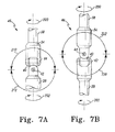
- the input coupling 34 is adapted to rotate as indicated by the arrow 200. While the arrow 200 indicates a particular direction of rotation, and only one direction, it should be appreciated that the input coupling 34 may be rotated in the opposite direction. Since the input coupling 34 is coupled to the drive connector 28 via the drive interface 40, the drive connector 28 likewise rotates in the direction of rotation of the input coupling 34 as indicated by the arrow 202.
- the drive interface 40 and thus the input coupling 34 are connected to the drive connector 28 via the pivot pin or hinge 42.
- the input coupling 34 and the drive interface 40 pivots about the pivot pin 42 and the drive coupling 28 as indicated by the arrow 210. If the drive connector 28 is held stationary, the input coupling 34 and the drive interface 40 are able to pivot about the pivot pin 42 in a 180° arc as represented by the arrow 210.
- the rotary motion device (not shown in Fig. 7A) may be positioned in various angular orientations while the reamer 50 is held stationary.
- the drive coupling 28 pivots about the pivot pin 42, the input coupling 34 and drive interface 40 as indicated by the arrow 212. If the input coupling 34 is held stationary, the drive coupling 28 and the drive interface 40 are able to pivot about the pivot pin 42 in a 180° arc as represented by the arrow 212. Thus, the rotary motion device may be held stationary while the reamer 50 may be positioned in various angular orientations.
- the input coupling 34 pivots about the pivot pin 44, the drive interface 40 and the drive coupling 28 as indicated by the arrow 222. If the drive connector 28 is held stationary, the input coupling 34 is able to pivot about the pivot pin 44 in a 180° arc as represented by the arrow 222.
- the rotary motion device (not shown in Fig. 7B) may be positioned in various angular orientations while the reamer 50 is held stationary.
- the drive coupling 28 and the drive interface 40 pivots about the pivot pin 44 and the input coupling 34 as indicated by the arrow 220. If the input coupling 34 is held stationary, the drive coupling 28 and the drive interface 40 are able to pivot about the pivot pin 44 in a 180° arc as represented by the arrow 220. Thus, the rotary motion device may be held stationary while the reamer 50 may be positioned in various angular orientations.
- the drive connector 28 defines a bottom portion 48 that has a receptor 52, here embodied as a mortise, concavity or like (see e.g., Figs. 2 and 3).
- the mortise 52 is configured and/or adapted to receive and/or allow connection with the reamer 50. In this manner, rotation of the drive connector 28 rotates the reamer 50.
- the reamer 50 is configured, adapted, and/or operative to mill bone matter as it is extended into a bone. This will be explained further in connection with an exemplary procedure utilizing the subject exemplary bone milling apparatus 10.
- the reamer 50 consists of a plurality of segments, cutters, cutting elements, cutting segments, or the like 54 and a termination segment 56.
- the cutting segments 54 are linked and/or coupled to one another and extend from the drive connector 28 to the termination segment 56.
- the cutting segments 54 are linked to provide flexibility to the reamer 50 and/or allow the reamer 50 to bend or curve. Additionally, the cutting segments 54 and the termination segment 56 are rotatable in the curved position.
- the reamer 50 may consist of as many cutting segments 54 as appropriate. As detailed below, the reamer 50 may be formed into any curve, radius of curvature (rate of curve) or the like.
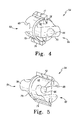
- each cutting segment 54 is preferably identical or at least substantially identical in shape, but not necessarily in size (e.g. diameter) with one another. Therefore, the cutting segment 54 shown in Figs. 4-6 represents each cutting segment 54 of the reamer 50. It should, however, be appreciated that the cutting segments may differ from one another if desired. Variations may be used for various purposes.
- the cutting segment 54 is defined by a body 60 preferably formed of stainless steel or other appropriate material.
- the body 60 is preferably substantially cylindrical but may take any other suitable shape, depending on the desired shape of a bore resulting from milling by the reamer 50/cutting segments 54.
- the body 60 has a first end 62 and a second end 64 each of which is named arbitrarily.
- a cannula, bore or hole 66 extends preferably centrally through the body 60.
- the cannula 66 is sized to extend about a shaft such that the body 60 is retained on the shaft.
- the cannula 66 defines an axis of rotation of the cutting segment 54.
- the first end 62 has a mortise, concavity or concave structure 68 while the second end has a tenon, convexity or convex structure 70.
- the mortise 68 extends generally perpendicular to the cannula/axis of rotation 66.
- the tenon 70 likewise extends generally perpendicular to the cannula/axis of rotation 66.
- the mortise 68 and tenon 70 are complementary in structure such that a tenon 70 of another cutting segment 54 is receivable in the present mortise 68 and, a mortise 68 of another cutting segment 70 receives the present tenon 70. In this manner, the cutting segments 54 are linked to one another.
- Such linking allows the reamer 50 to be of any length and flexible. Such flexibility exists because of a pivoting motion between the mortise or concavity and the tenon or convexity. It should be appreciated that structures other than those depicted for the concavity and the convexity may be utilized and is contemplated.
- the body 60 also includes a first cutting tooth, blade, structure, feature, surface or the like 72 and a second cutting tooth, blade, structure, feature, surface, or the like 74.
- Each cutting surface 72 and 74 extends longitudinally along the outside of the body 60 and a distance axially therefrom. A diameter from axial tips of the cutting surfaces 72 and 74 determines the diameter of the milled portion of the bone. Thus, not only does the diameter of the body 60 determine the diameter of the milled portion of the bone, but the axial lengths of the cutting teeth. Additionally, the first and second surfaces 72 and 74 are disposed diametrically opposite one another.
- each cutting surface is configured to mill bone in a single rotational direction. It should be appreciated, while not shown, that cutting surfaces may be provided that allow cutting in both rotational directions. It should also be appreciated that as an alternative embodiment, the mortise and tenon of the body 60 may be reversed and/or that each cutting segment 54 of the reamer 50 may be flipped 180°.
- each cutting surface may consist of several, separate surfaces that may be straight or curved.
- a plurality of surfaces may be provided that are straight, curved, spiralled, or a combination thereof.
- Various combinations and/or configurations of cutting surfaces are contemplated.
- a first cutting segment 54 thereof is coupled to the lower portion 48 of the drive connector 28.
- the tenon 70 of the first cutting segment 54 is linked to the mortise 52 of the lower portion 48 via the drive connector 28.
- a second cutting segment 54 is in like manner coupled or linked to the first cutting segment 54 in essentially axial alignment therewith.
- a given number of cutting segments 54 are then linked to each other in substantially axial alignment with one another with a last cutting segment 54 linked to the end or termination segment 56.
- the number of cutting segments 54 of the reamer 50 is determined by the length of each cutting segment 54 and the overall length of the guide shaft 80. Additionally, each cutting segment 54 may have the same diameter (i.e.
- each cutting segment 54 may have the same diameter while others may have a different diameter, each cutting segment 54 may be different in diameter, or other various combinations. If each cutting segment has a different diameter, the diameters preferably increase from a beginning of the reamer (distal the input connector) to the end of the reamer (proximate the input connector).
- a reamer 300 is depicted.
- the reamer 300 has an input connector segment 310 and an ending segment 320 both of which are in like manner to the other embodiments.
- the reamer 300 forms a cone wherein the cutting segment 330 is smaller in diameter than an adjacent cutting segment 332, which is smaller in diameter than an adjacent cutting segment 334, which is smaller in diameter than an adjacent cutting segment 336, which is smaller in diameter than an adjacent cutting segment 338.
- any number of cutting segments may make up the reamer 300.
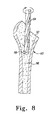
- the bone milling apparatus 10 is shown with most or all of the cutting segments 54 removed to illustrate that the bone milling apparatus 10 further includes a guide in the form of a shaft 80.
- the shaft 80 is provided in a predetermined curve that extends from the drive connector 28 to the base 20. The rate of curvature between distance D from the yoke 26 to the base 20 (see Fig. 1) is determined based on the desired amount of bone to be milled and/or the desired geometry of the bone area to be milled.
- the shaft 80 provides a guide curve for milling by the reamer 50.
- the shaft 80 is stationary with respect to the cutting segments 54 (reamer 50) that rotate about the shaft 80.
- Each cutting segment 54 is situated on the shaft 80. Particularly, each cutting segment 54 is rotatably retained on the shaft 80.
- the shaft 80 extends through the bore 66 of the body 60 of the respective cutting segment 54. As well, all of the cutting segments 54 rotate in unison which constitute the reamer 50.
- the frame 12 is operative to support shafts of different lengths and/or curvatures. These shafts are replaceable within the frame 12 preferably in a modular fashion.
- the cutting segments 54 are interchangeable with the various shafts, that is the cutting segments 54 may be used with any of the various shafts.
- the shaft 80 determines the curve of the reamer 50. Since the reamer 50 is comprised of a plurality of cutting segments, the reamer 50 can bend or curve and is thus flexible. As such, the shaft 80 that retains the plurality of cutting segments 54 may be of any curvature.
- the present bone milling apparatus 10 may thus be part of a kit in which shafts of various curves and/or rate of curvature are supplied along with a number of cutting segments. Curve guide cartridges (modular or replaceable shafts) may be provided that are accepted by the frame 12. In this manner a family of curves of varying radii may be supplied and used.
- a femur in cross-section
- a top portion of the femur 90 has been resected to provide a resected surface 92.
- Such resection is accomplished as is known in the art for the particular prosthesis to be implanted.
- the intramedullary canal 96 is drilled to create a bore 98.
- a standard reamer 94 is shown making the bore 98 in the intramedullary canal 96.
- other manners of providing a bore 98 in the intramedullary canal 96 may be used.
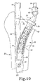
- Fig. 9 depicts the next step which is to advance the bone milling apparatus 10 into the femur 90.
- Attached to the milling apparatus 10 is a guide 100.
- the guide 100 is threadedly attached to the connector 22 prior to initial insertion of the bone milling apparatus 10.
- the guide 100 is placed in the bore 98 as the bone milling apparatus 10 is placed downwardly into the femur 90.
- the bone milling apparatus 10 is coupled to a power driver 102 that is operative to provide motive rotary power.
- the shaft 38 is coupled to the rotary power driver 102 such that shaft 38 rotates the coupling 28 which, in turn, rotates the drive connector 28.
- Rotation of the drive connector 28 rotates the reamer 50 about the shaft 80.
- the bone milling apparatus 10 is advanced into the femur 90.
- the cutting teeth of each cutting segment 54 mills bone during advancement.
- Fig. 9 depicts the rotary power device 102 in various positions to illustrate the nature of the multi-orientation joint/coupling 46.
- the rotary power device 102 may be held stationary while the milling device 10 may be positioned in various angular orientations.
- the bone milling apparatus 10 is shown advanced into the femur 90 such that the reamer 50 has milled a substantially triangular area in the femur 90 and/or when the curve substantially matches the patient's bone anatomy.
- the bone milling apparatus 10 is advanced into the femur 90 until the yoke 26 is proximate the resection surface 92 and/or the milled curve matches the medial endosteum.
- Fig. 11 depicts the prepared femur 90 in which an area 104 has been prepared (milled) by the bone milling apparatus 10.
- the prepared area 104 (triangular area) is ready to receive the implant (not shown).
- the subject invention provides various features and/or advantages.
- the subject invention provides interlocking cutting segments that exist within a generally cylindrical geometry when the bone milling apparatus 10 is in a rest state.
- the reamer 50 of the bone milling apparatus 10 is flexible and cannulated. Such flexibility can accommodate a range of guide curves (shafts) that are consistent with an associated implant geometry that a user is duplicating in bone preparation.
- the entire length of the flexible reamer 50 provides cutting or milling of bone and can be driven by standard reamer driver power equipment. Since the reamer 50 is comprised of a plurality of individual segments, an individual segment can be replaced when dull. This obviates the need to replace the entire reamer.
- kits may provide a plurality of sets of cutting segments, with each set of cutting segments of a particular diameter. For example, one set of cutting segments may have a cutting diameter of 9 mm, while another set of cutting segments may have a cutting diameter of 25 mm. Sets of a range of cutting diameter segments from 9 mm to 27 mm, for example, in 1.5 mm to 2.0 mm increments may be provided as well. Different cutting diameter cutting segments may also be mixed and matched if desired. Various combinations are contemplated.
Applications Claiming Priority (2)
| Application Number | Priority Date | Filing Date | Title |
|---|---|---|---|
| US113171 | 2002-03-29 | ||
| US10/113,171 US6949101B2 (en) | 2002-03-29 | 2002-03-29 | Medical instrument for milling a curved path in bone and procedure |
Publications (2)
| Publication Number | Publication Date |
|---|---|
| EP1348384A2 true EP1348384A2 (fr) | 2003-10-01 |
| EP1348384A3 EP1348384A3 (fr) | 2003-11-19 |
Family
ID=27804443
Family Applications (1)
| Application Number | Title | Priority Date | Filing Date |
|---|---|---|---|
| EP03252009A Withdrawn EP1348384A3 (fr) | 2002-03-29 | 2003-03-29 | Instrument médical pour fraiser une courbe dans un os |
Country Status (4)
| Country | Link |
|---|---|
| US (1) | US6949101B2 (fr) |
| EP (1) | EP1348384A3 (fr) |
| JP (1) | JP2003339724A (fr) |
| AU (1) | AU2003203559B2 (fr) |
Cited By (30)
| Publication number | Priority date | Publication date | Assignee | Title |
|---|---|---|---|---|
| EP1410765A2 (fr) * | 2002-10-08 | 2004-04-21 | Zimmer Technology, Inc. | Procédé et dispositif pour réduire des fractures femorales |
| WO2005060839A1 (fr) * | 2003-12-24 | 2005-07-07 | Depuy International Limited | Guide d'alesoir et procede |
| EP1563795A1 (fr) * | 2003-12-30 | 2005-08-17 | Depuy Products, Inc. | Appareils pour le fraisage d'os à invasion minimale |
| WO2006091704A1 (fr) * | 2005-02-22 | 2006-08-31 | Smith & Nephew, Inc. | Systeme de fraisage en ligne |
| FR2886839A1 (fr) * | 2005-06-14 | 2006-12-15 | Sdgi Holdings Inc | Dispositif pour menager une cavite a l'interieur d'un disque intervertebral. |
| US7258692B2 (en) | 2000-03-07 | 2007-08-21 | Zimmer, Inc. | Method and apparatus for reducing femoral fractures |
| EP1961389A1 (fr) * | 2007-02-26 | 2008-08-27 | Benoist Girard Sas | Appareil de préparation de cavité de tige de prothèse dans un fémur |
| US7485119B2 (en) | 2000-03-07 | 2009-02-03 | Zimmer Technology, Inc. | Method and apparatus for reducing femoral fractures |
| US7488329B2 (en) | 2000-03-07 | 2009-02-10 | Zimmer Technology, Inc. | Method and apparatus for reducing femoral fractures |
| US7764985B2 (en) | 2003-10-20 | 2010-07-27 | Smith & Nephew, Inc. | Surgical navigation system component fault interfaces and related processes |
| US7794467B2 (en) | 2003-11-14 | 2010-09-14 | Smith & Nephew, Inc. | Adjustable surgical cutting systems |
| US7862570B2 (en) | 2003-10-03 | 2011-01-04 | Smith & Nephew, Inc. | Surgical positioners |
| US8109942B2 (en) | 2004-04-21 | 2012-02-07 | Smith & Nephew, Inc. | Computer-aided methods, systems, and apparatuses for shoulder arthroplasty |
| US8287538B2 (en) | 2008-01-14 | 2012-10-16 | Conventus Orthopaedics, Inc. | Apparatus and methods for fracture repair |
| US8419799B2 (en) | 2003-06-25 | 2013-04-16 | Depuy Products, Inc. | Assembly tool for modular implants and associated method |
| US8597298B2 (en) | 2006-09-29 | 2013-12-03 | DePuy Synthes Products, LLC | Proximal reamer |
| US8685036B2 (en) | 2003-06-25 | 2014-04-01 | Michael C. Jones | Assembly tool for modular implants and associated method |
| US8790346B2 (en) | 2003-06-25 | 2014-07-29 | DePuy Synthes Products, LLC | Modular tapered reamer for bone preparation and associated method |
| US8828003B2 (en) | 2008-09-30 | 2014-09-09 | DePuy Synthes Products, LLC | Minimally invasive bone miller apparatus |
| US8906022B2 (en) | 2010-03-08 | 2014-12-09 | Conventus Orthopaedics, Inc. | Apparatus and methods for securing a bone implant |
| US8961518B2 (en) | 2010-01-20 | 2015-02-24 | Conventus Orthopaedics, Inc. | Apparatus and methods for bone access and cavity preparation |
| US8998919B2 (en) | 2003-06-25 | 2015-04-07 | DePuy Synthes Products, LLC | Assembly tool for modular implants, kit and associated method |
| US9095452B2 (en) | 2010-09-01 | 2015-08-04 | DePuy Synthes Products, Inc. | Disassembly tool |
| US9101495B2 (en) | 2010-06-15 | 2015-08-11 | DePuy Synthes Products, Inc. | Spiral assembly tool |
| US9119601B2 (en) | 2007-10-31 | 2015-09-01 | DePuy Synthes Products, Inc. | Modular taper assembly device |
| US9717545B2 (en) | 2007-10-30 | 2017-08-01 | DePuy Synthes Products, Inc. | Taper disengagement tool |
| US9730739B2 (en) | 2010-01-15 | 2017-08-15 | Conventus Orthopaedics, Inc. | Rotary-rigid orthopaedic rod |
| US9737405B2 (en) | 2011-04-06 | 2017-08-22 | DePuy Synthes Products, Inc. | Orthopaedic surgical procedure for implanting a revision hip prosthesis |
| US10022132B2 (en) | 2013-12-12 | 2018-07-17 | Conventus Orthopaedics, Inc. | Tissue displacement tools and methods |
| US10918426B2 (en) | 2017-07-04 | 2021-02-16 | Conventus Orthopaedics, Inc. | Apparatus and methods for treatment of a bone |
Families Citing this family (67)
| Publication number | Priority date | Publication date | Assignee | Title |
|---|---|---|---|---|
| US7785329B2 (en) * | 2002-04-30 | 2010-08-31 | Greatbatch Medical S.A. | Reamer spindle for minimally invasive joint surgery |
| US7217271B2 (en) * | 2002-09-13 | 2007-05-15 | Symmetry Medical, Inc. | Orthopaedic reamer driver for minimally invasive surgery |
| US7393355B2 (en) * | 2003-02-04 | 2008-07-01 | Howmedica Osteonics Corp. | Femoral guide and pivoting reamer |
| US20040267267A1 (en) * | 2003-06-25 | 2004-12-30 | Daniels David Wayne | Non-linear reamer for bone preparation and associated method |
| US8657824B2 (en) * | 2003-11-18 | 2014-02-25 | Smith & Nephew, Inc. | Universal double offset surgical instrument |
| US7591821B2 (en) | 2003-11-18 | 2009-09-22 | Smith & Nephew, Inc. | Surgical technique and instrumentation for minimal incision hip arthroplasty surgery |
| NZ550050A (en) * | 2004-03-26 | 2009-03-31 | Synthes Gmbh | Articulated bone screw |
| US20060229624A1 (en) | 2005-03-31 | 2006-10-12 | Zimmer Technology, Inc. | Orthopaedic cutting instrument and method |
| US8398639B2 (en) * | 2005-09-29 | 2013-03-19 | Symmetry Medical Manufacturing, Inc. | Minimally invasive surgical driver |
| US20070093840A1 (en) * | 2005-10-06 | 2007-04-26 | Pacelli Nicolas J | Flexible shaft |
| EP2035723A4 (fr) | 2006-06-20 | 2011-11-30 | Aortx Inc | Arbre de torsion et transmission de couple |
| US7992878B2 (en) * | 2006-07-31 | 2011-08-09 | Warsaw Orthopedic, Inc | Helical lead for a drive shaft collet |
| EP2114262A1 (fr) * | 2007-02-13 | 2009-11-11 | Orthogroup, Inc. | Système de perçage pour des implants de cotyle |
| AU2008228710A1 (en) | 2007-03-22 | 2008-09-25 | Novalign Orthopaedics, Inc. | Segmented intramedullary structure |
| US20080287958A1 (en) * | 2007-05-14 | 2008-11-20 | Howmedica Osteonics Corp. | Flexible intramedullary rod |
| US7854767B2 (en) * | 2007-06-15 | 2010-12-21 | Zimmer, Inc. | Single entry portal implant |
| US8092722B2 (en) * | 2008-09-30 | 2012-01-10 | Sabic Innovative Plastics Ip B.V. | Varnish compositions for electrical insulation and method of using the same |
| EP4279032A3 (fr) * | 2009-07-10 | 2024-01-17 | Implantica Patent Ltd. | Instrument pour l'articulation de la hanche |
| US9241721B2 (en) * | 2009-07-10 | 2016-01-26 | Peter Forsell | Hip joint instrument and method |
| US8454608B2 (en) * | 2009-12-15 | 2013-06-04 | Greatbatch Ltd. | Disposable flex reamer |
| US8801716B2 (en) | 2010-08-24 | 2014-08-12 | Biomet Manufacturing, Llc | Cartilage repair system with flexible trephine |
| US20120089146A1 (en) | 2010-10-06 | 2012-04-12 | Howmedica Osteonics Corp. | System and method of bone preparation |
| FR2967046A1 (fr) | 2010-11-10 | 2012-05-11 | Tornier Sa | Fraiseuse orthopedique de preparation osseuse, en particulier de preparation glenoidienne |
| US9119639B2 (en) | 2011-08-09 | 2015-09-01 | DePuy Synthes Products, Inc. | Articulated cavity creator |
| US9144506B2 (en) * | 2011-08-11 | 2015-09-29 | Jeff Phelps | Interbody axis cage |
| US20130090690A1 (en) * | 2011-10-06 | 2013-04-11 | David A. Walsh | Dynamic Rod Assembly |
| US9839435B2 (en) | 2011-11-14 | 2017-12-12 | The University Of British Columbia | Intramedullary fixation system for management of pelvic and acetabular fractures |
| EP2787901B1 (fr) | 2011-12-09 | 2017-06-07 | Howmedica Osteonics Corp. | Instrument d'alésage chirurgical pour la formation d'une cavité osseuse |
| US9149282B2 (en) | 2011-12-30 | 2015-10-06 | Howmedica Osteonics Corp. | Systems and methods for preparing bone voids to receive a prosthesis |
| US9629646B2 (en) | 2012-07-11 | 2017-04-25 | Jens Kather | Curved burr surgical instrument |
| US9439693B2 (en) | 2013-02-01 | 2016-09-13 | DePuy Synthes Products, Inc. | Steerable needle assembly for use in vertebral body augmentation |
| US20140235361A1 (en) * | 2013-02-15 | 2014-08-21 | Cardiacmd, Inc. | Torque Shaft and Torque Shaft Drive |
| US20170319348A1 (en) | 2015-08-10 | 2017-11-09 | Catalyst Orthoscience Inc. | Arthroplasty prostheses with multi-axis fixation |
| US9775716B2 (en) | 2013-03-11 | 2017-10-03 | Catalyst Orthoscience Inc. | Glenoid arthroplasty |
| US10973646B2 (en) | 2013-03-11 | 2021-04-13 | Catalyst Orthoscience Inc. | Stabilized drill guide |
| US9814588B2 (en) | 2015-08-10 | 2017-11-14 | Catalyst Orthoscience Inc. | Glenoid arthroplasty with multi-directional fixation |
| US11007063B2 (en) * | 2013-03-11 | 2021-05-18 | Catalyst Orthoscience Inc. | Offset reamers |
| US9814471B2 (en) * | 2013-03-11 | 2017-11-14 | Catalyst Orthoscience Inc. | Glenoid arthroplasty and offset reamers |
| AU2014239941C1 (en) * | 2013-03-14 | 2017-09-07 | Wright Medical Technology, Inc. | Intramedullary ankle technique and system |
| WO2015134750A1 (fr) | 2014-03-06 | 2015-09-11 | University Of British Columbia | Dispositif de fixation intramédullaire à forme adaptable |
| US10028838B2 (en) | 2014-06-30 | 2018-07-24 | Tornier, Inc. | Augmented glenoid components and devices for implanting the same |
| US11234826B2 (en) | 2014-06-30 | 2022-02-01 | Howmedica Osteonics Corp. | Augmented glenoid components and devices for implanting the same |
| EP4245233A3 (fr) * | 2014-10-14 | 2023-12-06 | The University of British Columbia | Systèmes de fixation d'os intramédullaire |
| WO2016090018A1 (fr) | 2014-12-02 | 2016-06-09 | Akp Consulting | Dispositifs de compression active, procédés d'assemblage et procédés d'utilisation |
| US10149763B2 (en) | 2015-01-12 | 2018-12-11 | Howmedica Osteonics Corp. | Multipurpose void filling prosthesis |
| US10485595B2 (en) | 2015-07-13 | 2019-11-26 | IntraFuse, LLC | Flexible bone screw |
| US10499960B2 (en) | 2015-07-13 | 2019-12-10 | IntraFuse, LLC | Method of bone fixation |
| US10154863B2 (en) | 2015-07-13 | 2018-12-18 | IntraFuse, LLC | Flexible bone screw |
| US10492838B2 (en) | 2015-07-13 | 2019-12-03 | IntraFuse, LLC | Flexible bone implant |
| US20170208860A1 (en) * | 2016-01-22 | 2017-07-27 | Ii Daniel M. Evans | Smoking pipe assembly |
| US10335170B2 (en) | 2016-02-12 | 2019-07-02 | Viant As&O Holdings, Llc | Cutting heads for intramedullary reamers |
| US11224467B2 (en) | 2016-02-26 | 2022-01-18 | Activortho, Inc. | Active compression apparatus, methods of assembly and methods of use |
| WO2017147537A1 (fr) | 2016-02-26 | 2017-08-31 | Activortho, Inc. | Appareil de compression active, procédés d'assemblage et procédés d'utilisation |
| US10653431B2 (en) | 2016-06-14 | 2020-05-19 | Medos International Sarl | Drill assemblies and methods for drilling into bone |
| WO2018022227A1 (fr) | 2016-07-28 | 2018-02-01 | Tornier, Inc. | Composant d'ancrage de prothèse sans tige |
| US10405872B2 (en) | 2016-08-14 | 2019-09-10 | Viant As&O Holdings, Llc | Cutting head for an intramedullary reamer |
| EP3522803A4 (fr) | 2016-10-05 | 2020-05-27 | The University of British Columbia | Dispositif de fixation intramédullaire avec interface de verrouillage de forme |
| US20180147714A1 (en) * | 2016-11-28 | 2018-05-31 | General Electric Company | Multi-joint tools with cylindrical segments |
| US10631881B2 (en) | 2017-03-09 | 2020-04-28 | Flower Orthopedics Corporation | Plating depth gauge and countersink instrument |
| WO2019161436A1 (fr) * | 2018-02-22 | 2019-08-29 | PMSW Research Pty Ltd | Améliorations apportées à la reconstruction de ligament croisé antérieur |
| US11123085B2 (en) | 2018-04-11 | 2021-09-21 | Howmedica Osteonics Corp. | Cutting tool positioned by flexible rod for revision surgery |
| CN112912022A (zh) | 2018-10-17 | 2021-06-04 | 不列颠哥伦比亚大学 | 骨固定装置及系统 |
| KR102245962B1 (ko) * | 2019-05-15 | 2021-04-29 | 한국과학기술연구원 | 구름 조인트와 돌기 부재를 이용한 관절 구조체 및 이를 구비한 튜브 삽입형 장치 |
| AU2020204539A1 (en) | 2019-07-12 | 2021-01-28 | Howmedica Osteonics Corp. | Augmented glenoid design |
| US11426285B2 (en) | 2019-09-05 | 2022-08-30 | Howmedica Osteonics Corp. | Truss glenoid augment |
| AU2021200854A1 (en) | 2020-03-03 | 2021-09-16 | Howmedica Osteonics Corp. | Glenoid implant with additively manufactured fixation posts |
| US20220145913A1 (en) * | 2020-11-06 | 2022-05-12 | Guangzhou Aquila Precise Tools Limited | Elastic Connecting Element, Processing Method Thereof and Flexible Drill the Including Elastic Connecting Element |
Citations (2)
| Publication number | Priority date | Publication date | Assignee | Title |
|---|---|---|---|---|
| US5540694A (en) | 1993-06-01 | 1996-07-30 | Joint Medical Products Corporation | Instrument for cutting bone |
| US6053922A (en) | 1995-07-18 | 2000-04-25 | Krause; William R. | Flexible shaft |
Family Cites Families (18)
| Publication number | Priority date | Publication date | Assignee | Title |
|---|---|---|---|---|
| US4328839A (en) * | 1980-09-19 | 1982-05-11 | Drilling Development, Inc. | Flexible drill pipe |
| US4706659A (en) | 1984-12-05 | 1987-11-17 | Regents Of The University Of Michigan | Flexible connecting shaft for intramedullary reamer |
| GB8516167D0 (en) * | 1985-06-26 | 1985-07-31 | Finsbury Instr Ltd | Surgical tool |
| US4751922A (en) | 1986-06-27 | 1988-06-21 | Dipietropolo Al | Flexible medullary reamer |
| US4790852A (en) | 1986-09-15 | 1988-12-13 | Joint Medical Products Corporation | Sleeves for affixing artificial joints to bone |
| CH670198A5 (fr) | 1986-10-02 | 1989-05-31 | Sulzer Ag | |
| US5203595A (en) | 1990-02-02 | 1993-04-20 | Pfizer Hospital Products Group, Inc. | Dovetail-type coupling device and method |
| GB9026592D0 (en) * | 1990-12-06 | 1991-01-23 | Meswania Jayantilal M | Surgical instrument |
| US5342363A (en) | 1992-11-30 | 1994-08-30 | Wright Medical Technology, Inc. | Medical instrument and procedure |
| DE69431002T2 (de) | 1993-05-27 | 2003-05-08 | Stryker Technologies Corp | Flexible Reibahle für einen Knochenmarkkanal |
| FR2708462A1 (fr) | 1993-07-30 | 1995-02-10 | Tech Innovations Medicales | Instrumentation de reprise de prothèse totale de hanche. |
| US5468243A (en) | 1993-10-27 | 1995-11-21 | Halpern; Alan A. | Femoral superior neck remodelling means and method |
| US5527316A (en) | 1994-02-23 | 1996-06-18 | Stone; Kevin T. | Surgical reamer |
| US5851208A (en) | 1996-10-15 | 1998-12-22 | Linvatec Corporation | Rotatable surgical burr |
| US5766081A (en) * | 1996-12-10 | 1998-06-16 | Hand Tool Design Corporation | Modified ear design to avoid lock up of universal joint |
| US6106528A (en) * | 1997-02-11 | 2000-08-22 | Orthomatrix, Inc. | Modular intramedullary fixation system and insertion instrumentation |
| DE19711532C1 (de) | 1997-03-20 | 1998-10-22 | Philipp Dr Med Lubinus | Fräserwerkzeug zum Ausräumen des Femur-Markraums und in diesen Raum einzusetzende Hüftprothese |
| US20030027641A1 (en) * | 2001-07-16 | 2003-02-06 | Parsons James K. | Universal joint and coupling assembly |
-
2002
- 2002-03-29 US US10/113,171 patent/US6949101B2/en not_active Expired - Lifetime
-
2003
- 2003-03-28 AU AU2003203559A patent/AU2003203559B2/en not_active Ceased
- 2003-03-29 EP EP03252009A patent/EP1348384A3/fr not_active Withdrawn
- 2003-03-31 JP JP2003096007A patent/JP2003339724A/ja active Pending
Patent Citations (2)
| Publication number | Priority date | Publication date | Assignee | Title |
|---|---|---|---|---|
| US5540694A (en) | 1993-06-01 | 1996-07-30 | Joint Medical Products Corporation | Instrument for cutting bone |
| US6053922A (en) | 1995-07-18 | 2000-04-25 | Krause; William R. | Flexible shaft |
Cited By (56)
| Publication number | Priority date | Publication date | Assignee | Title |
|---|---|---|---|---|
| US7258692B2 (en) | 2000-03-07 | 2007-08-21 | Zimmer, Inc. | Method and apparatus for reducing femoral fractures |
| US7488329B2 (en) | 2000-03-07 | 2009-02-10 | Zimmer Technology, Inc. | Method and apparatus for reducing femoral fractures |
| US7485119B2 (en) | 2000-03-07 | 2009-02-03 | Zimmer Technology, Inc. | Method and apparatus for reducing femoral fractures |
| EP1410765A2 (fr) * | 2002-10-08 | 2004-04-21 | Zimmer Technology, Inc. | Procédé et dispositif pour réduire des fractures femorales |
| EP1410765A3 (fr) * | 2002-10-08 | 2005-09-07 | Zimmer Technology, Inc. | Procédé et dispositif pour réduire des fractures femorales |
| US8998919B2 (en) | 2003-06-25 | 2015-04-07 | DePuy Synthes Products, LLC | Assembly tool for modular implants, kit and associated method |
| US9381097B2 (en) | 2003-06-25 | 2016-07-05 | DePuy Synthes Products, Inc. | Assembly tool for modular implants, kit and associated method |
| US8790346B2 (en) | 2003-06-25 | 2014-07-29 | DePuy Synthes Products, LLC | Modular tapered reamer for bone preparation and associated method |
| US8685036B2 (en) | 2003-06-25 | 2014-04-01 | Michael C. Jones | Assembly tool for modular implants and associated method |
| US8419799B2 (en) | 2003-06-25 | 2013-04-16 | Depuy Products, Inc. | Assembly tool for modular implants and associated method |
| US7862570B2 (en) | 2003-10-03 | 2011-01-04 | Smith & Nephew, Inc. | Surgical positioners |
| US7764985B2 (en) | 2003-10-20 | 2010-07-27 | Smith & Nephew, Inc. | Surgical navigation system component fault interfaces and related processes |
| US7794467B2 (en) | 2003-11-14 | 2010-09-14 | Smith & Nephew, Inc. | Adjustable surgical cutting systems |
| WO2005060839A1 (fr) * | 2003-12-24 | 2005-07-07 | Depuy International Limited | Guide d'alesoir et procede |
| AU2004242494B2 (en) * | 2003-12-30 | 2010-05-27 | Depuy Products, Inc. | Minimally invasive bone miller apparatus |
| US7785328B2 (en) | 2003-12-30 | 2010-08-31 | Depuy Products, Inc. | Minimally invasive bone miller apparatus |
| EP1563795A1 (fr) * | 2003-12-30 | 2005-08-17 | Depuy Products, Inc. | Appareils pour le fraisage d'os à invasion minimale |
| US8109942B2 (en) | 2004-04-21 | 2012-02-07 | Smith & Nephew, Inc. | Computer-aided methods, systems, and apparatuses for shoulder arthroplasty |
| AU2006216653B2 (en) * | 2005-02-22 | 2012-03-15 | Smith & Nephew, Inc. | In-line milling system |
| US8177788B2 (en) | 2005-02-22 | 2012-05-15 | Smith & Nephew, Inc. | In-line milling system |
| WO2006091704A1 (fr) * | 2005-02-22 | 2006-08-31 | Smith & Nephew, Inc. | Systeme de fraisage en ligne |
| FR2886839A1 (fr) * | 2005-06-14 | 2006-12-15 | Sdgi Holdings Inc | Dispositif pour menager une cavite a l'interieur d'un disque intervertebral. |
| US8852188B2 (en) | 2006-09-29 | 2014-10-07 | DePuy Synthes Products, LLC | Proximal reamer |
| US8597298B2 (en) | 2006-09-29 | 2013-12-03 | DePuy Synthes Products, LLC | Proximal reamer |
| US8852189B2 (en) | 2006-09-29 | 2014-10-07 | DePuy Synthes Products, LLC | Proximal reamer |
| AU2008200803B2 (en) * | 2007-02-26 | 2012-09-06 | Stryker Ireland Limited | Apparatus for preparing a prosthetic stem cavity in a femur |
| EP1961389A1 (fr) * | 2007-02-26 | 2008-08-27 | Benoist Girard Sas | Appareil de préparation de cavité de tige de prothèse dans un fémur |
| US9717545B2 (en) | 2007-10-30 | 2017-08-01 | DePuy Synthes Products, Inc. | Taper disengagement tool |
| US9119601B2 (en) | 2007-10-31 | 2015-09-01 | DePuy Synthes Products, Inc. | Modular taper assembly device |
| US11399878B2 (en) | 2008-01-14 | 2022-08-02 | Conventus Orthopaedics, Inc. | Apparatus and methods for fracture repair |
| US8287538B2 (en) | 2008-01-14 | 2012-10-16 | Conventus Orthopaedics, Inc. | Apparatus and methods for fracture repair |
| US10603087B2 (en) | 2008-01-14 | 2020-03-31 | Conventus Orthopaedics, Inc. | Apparatus and methods for fracture repair |
| US9788870B2 (en) | 2008-01-14 | 2017-10-17 | Conventus Orthopaedics, Inc. | Apparatus and methods for fracture repair |
| US9517093B2 (en) | 2008-01-14 | 2016-12-13 | Conventus Orthopaedics, Inc. | Apparatus and methods for fracture repair |
| US8828003B2 (en) | 2008-09-30 | 2014-09-09 | DePuy Synthes Products, LLC | Minimally invasive bone miller apparatus |
| US9730739B2 (en) | 2010-01-15 | 2017-08-15 | Conventus Orthopaedics, Inc. | Rotary-rigid orthopaedic rod |
| US8961518B2 (en) | 2010-01-20 | 2015-02-24 | Conventus Orthopaedics, Inc. | Apparatus and methods for bone access and cavity preparation |
| US9848889B2 (en) | 2010-01-20 | 2017-12-26 | Conventus Orthopaedics, Inc. | Apparatus and methods for bone access and cavity preparation |
| US8906022B2 (en) | 2010-03-08 | 2014-12-09 | Conventus Orthopaedics, Inc. | Apparatus and methods for securing a bone implant |
| US9993277B2 (en) | 2010-03-08 | 2018-06-12 | Conventus Orthopaedics, Inc. | Apparatus and methods for securing a bone implant |
| US10166118B2 (en) | 2010-06-15 | 2019-01-01 | DePuy Synthes Products, Inc. | Spiral assembly tool |
| US9101495B2 (en) | 2010-06-15 | 2015-08-11 | DePuy Synthes Products, Inc. | Spiral assembly tool |
| US9867720B2 (en) | 2010-09-01 | 2018-01-16 | DePuy Synthes Products, Inc. | Disassembly tool |
| US9095452B2 (en) | 2010-09-01 | 2015-08-04 | DePuy Synthes Products, Inc. | Disassembly tool |
| US10292837B2 (en) | 2010-09-01 | 2019-05-21 | Depuy Synthes Products Inc. | Disassembly tool |
| US9949833B2 (en) | 2011-04-06 | 2018-04-24 | DePuy Synthes Products, Inc. | Finishing RASP and orthopaedic surgical procedure for using the same to implant a revision hip prosthesis |
| US10226345B2 (en) | 2011-04-06 | 2019-03-12 | DePuy Synthes Products, Inc. | Version-replicating instrument and orthopaedic surgical procedure for using the same to implant a revision hip prosthesis |
| US10064725B2 (en) | 2011-04-06 | 2018-09-04 | DePuy Synthes Products, Inc. | Distal reamer for use during an orthopaedic surgical procedure to implant a revision hip prosthesis |
| US10603173B2 (en) | 2011-04-06 | 2020-03-31 | DePuy Synthes Products, Inc. | Orthopaedic surgical procedure for implanting a revision hip prosthesis |
| US10772730B2 (en) | 2011-04-06 | 2020-09-15 | DePuy Synthes Products, Inc. | Finishing rasp and orthopaedic surgical procedure for using the same to implant a revision hip prosthesis |
| US10888427B2 (en) | 2011-04-06 | 2021-01-12 | DePuy Synthes Products, Inc. | Distal reamer for use during an orthopaedic surgical procedure to implant a revision hip prosthesis |
| US10925739B2 (en) | 2011-04-06 | 2021-02-23 | DePuy Synthes Products, Inc. | Version-replicating instrument and orthopaedic surgical procedure for using the same to implant a revision hip prosthesis |
| US9737405B2 (en) | 2011-04-06 | 2017-08-22 | DePuy Synthes Products, Inc. | Orthopaedic surgical procedure for implanting a revision hip prosthesis |
| US10076342B2 (en) | 2013-12-12 | 2018-09-18 | Conventus Orthopaedics, Inc. | Tissue displacement tools and methods |
| US10022132B2 (en) | 2013-12-12 | 2018-07-17 | Conventus Orthopaedics, Inc. | Tissue displacement tools and methods |
| US10918426B2 (en) | 2017-07-04 | 2021-02-16 | Conventus Orthopaedics, Inc. | Apparatus and methods for treatment of a bone |
Also Published As
| Publication number | Publication date |
|---|---|
| US6949101B2 (en) | 2005-09-27 |
| JP2003339724A (ja) | 2003-12-02 |
| AU2003203559B2 (en) | 2008-10-02 |
| EP1348384A3 (fr) | 2003-11-19 |
| US20030187449A1 (en) | 2003-10-02 |
| AU2003203559A1 (en) | 2003-10-30 |
Similar Documents
| Publication | Publication Date | Title |
|---|---|---|
| US6949101B2 (en) | Medical instrument for milling a curved path in bone and procedure | |
| US5047032A (en) | Method and apparatus for cutting joint surfaces | |
| US7090677B2 (en) | Surgical milling instrument for shaping a bone cavity | |
| US8845643B2 (en) | Humeral rotating burr guide | |
| EP0666728B1 (fr) | Instrument de coupe orthopedique et dispositif prosthetique | |
| EP1563795B1 (fr) | Appareils pour le fraisage d'os à invasion minimale | |
| JP4436252B2 (ja) | リーマーアセンブリ | |
| EP2685905B1 (fr) | Combinaison alésoir/foret pour arthroplastie de l'épaule | |
| US7722615B2 (en) | Expandable surgical reaming tool | |
| US6997928B1 (en) | Apparatus for and method of providing a hip replacement | |
| US9763679B2 (en) | Combination driver/anti-rotation handle for shoulder arthroplasty | |
| WO1994009730A9 (fr) | Instrument de coupe orthopedique et dispositif prothetique | |
| US20230132876A1 (en) | Guided milling device for prosthetic surgery | |
| JP7462673B2 (ja) | 補綴手術用切削装置 | |
| EP0339879B1 (fr) | Prothèse de hanche | |
| EP3912570A1 (fr) | Instrument de coupe rotatif chirurgical | |
| US20220409384A1 (en) | Annular cutting tools for resecting a bone graft and related methods | |
| AU2018217341B2 (en) | Combination driver/anti-rotation handle for shoulder arthroplasty | |
| US20210378685A1 (en) | Reamer for Augmented Glenoid Implant | |
| US20220249102A1 (en) | Variable diameter reamer |
Legal Events
| Date | Code | Title | Description |
|---|---|---|---|
| PUAI | Public reference made under article 153(3) epc to a published international application that has entered the european phase |
Free format text: ORIGINAL CODE: 0009012 |
|
| AK | Designated contracting states |
Kind code of ref document: A2 Designated state(s): AT BE BG CH CY CZ DE DK EE ES FI FR GB GR HU IE IT LI LU MC NL PT RO SE SI SK TR |
|
| AX | Request for extension of the european patent |
Extension state: AL LT LV MK |
|
| PUAL | Search report despatched |
Free format text: ORIGINAL CODE: 0009013 |
|
| AK | Designated contracting states |
Kind code of ref document: A3 Designated state(s): AT BE BG CH CY CZ DE DK EE ES FI FR GB GR HU IE IT LI LU MC NL PT RO SE SI SK TR |
|
| AX | Request for extension of the european patent |
Extension state: AL LT LV MK |
|
| RIC1 | Information provided on ipc code assigned before grant |
Ipc: 7A 61B 17/17 B Ipc: 7A 61B 17/16 A |
|
| 17P | Request for examination filed |
Effective date: 20040512 |
|
| AKX | Designation fees paid |
Designated state(s): AT BE BG CH CY CZ DE DK EE ES FI FR GB GR HU IE IT LI LU MC NL PT RO SE SI SK TR |
|
| 17Q | First examination report despatched |
Effective date: 20060925 |
|
| 17Q | First examination report despatched |
Effective date: 20060925 |
|
| STAA | Information on the status of an ep patent application or granted ep patent |
Free format text: STATUS: THE APPLICATION IS DEEMED TO BE WITHDRAWN |
|
| 18D | Application deemed to be withdrawn |
Effective date: 20071002 |