EP2685905B1 - Combinaison alésoir/foret pour arthroplastie de l'épaule - Google Patents
Combinaison alésoir/foret pour arthroplastie de l'épaule Download PDFInfo
- Publication number
- EP2685905B1 EP2685905B1 EP12760199.5A EP12760199A EP2685905B1 EP 2685905 B1 EP2685905 B1 EP 2685905B1 EP 12760199 A EP12760199 A EP 12760199A EP 2685905 B1 EP2685905 B1 EP 2685905B1
- Authority
- EP
- European Patent Office
- Prior art keywords
- combination device
- glenoid
- section
- bore
- reaming
- Prior art date
- Legal status (The legal status is an assumption and is not a legal conclusion. Google has not performed a legal analysis and makes no representation as to the accuracy of the status listed.)
- Active
Links
- 238000011882 arthroplasty Methods 0.000 title description 7
- 241001653121 Glenoides Species 0.000 claims description 106
- 230000008878 coupling Effects 0.000 claims description 8
- 238000010168 coupling process Methods 0.000 claims description 8
- 238000005859 coupling reaction Methods 0.000 claims description 8
- 210000001991 scapula Anatomy 0.000 description 27
- 210000000988 bone and bone Anatomy 0.000 description 14
- 238000010276 construction Methods 0.000 description 11
- 238000000034 method Methods 0.000 description 7
- 210000000323 shoulder joint Anatomy 0.000 description 6
- 239000004698 Polyethylene Substances 0.000 description 3
- 239000004699 Ultra-high molecular weight polyethylene Substances 0.000 description 3
- 210000000845 cartilage Anatomy 0.000 description 3
- 239000011248 coating agent Substances 0.000 description 3
- 238000000576 coating method Methods 0.000 description 3
- 210000004095 humeral head Anatomy 0.000 description 3
- 210000002758 humerus Anatomy 0.000 description 3
- 239000007943 implant Substances 0.000 description 3
- -1 polyethylene Polymers 0.000 description 3
- 229920000573 polyethylene Polymers 0.000 description 3
- 229920000785 ultra high molecular weight polyethylene Polymers 0.000 description 3
- 239000000463 material Substances 0.000 description 2
- 210000005065 subchondral bone plate Anatomy 0.000 description 2
- 239000004705 High-molecular-weight polyethylene Substances 0.000 description 1
- 206010028391 Musculoskeletal Pain Diseases 0.000 description 1
- 208000002193 Pain Diseases 0.000 description 1
- 208000007613 Shoulder Pain Diseases 0.000 description 1
- 229910001069 Ti alloy Inorganic materials 0.000 description 1
- WAIPAZQMEIHHTJ-UHFFFAOYSA-N [Cr].[Co] Chemical class [Cr].[Co] WAIPAZQMEIHHTJ-UHFFFAOYSA-N 0.000 description 1
- 239000000853 adhesive Substances 0.000 description 1
- 230000001070 adhesive effect Effects 0.000 description 1
- 239000000560 biocompatible material Substances 0.000 description 1
- 230000006835 compression Effects 0.000 description 1
- 238000007906 compression Methods 0.000 description 1
- 238000005553 drilling Methods 0.000 description 1
- 238000002513 implantation Methods 0.000 description 1
- 230000013011 mating Effects 0.000 description 1
- 229910052751 metal Inorganic materials 0.000 description 1
- 239000002184 metal Substances 0.000 description 1
- 239000004033 plastic Substances 0.000 description 1
- 229920003023 plastic Polymers 0.000 description 1
- 238000002360 preparation method Methods 0.000 description 1
- 229910001256 stainless steel alloy Inorganic materials 0.000 description 1
Images


Classifications
-
- A—HUMAN NECESSITIES
- A61—MEDICAL OR VETERINARY SCIENCE; HYGIENE
- A61B—DIAGNOSIS; SURGERY; IDENTIFICATION
- A61B17/00—Surgical instruments, devices or methods, e.g. tourniquets
- A61B17/16—Bone cutting, breaking or removal means other than saws, e.g. Osteoclasts; Drills or chisels for bones; Trepans
- A61B17/1662—Bone cutting, breaking or removal means other than saws, e.g. Osteoclasts; Drills or chisels for bones; Trepans for particular parts of the body
- A61B17/1684—Bone cutting, breaking or removal means other than saws, e.g. Osteoclasts; Drills or chisels for bones; Trepans for particular parts of the body for the shoulder
-
- A—HUMAN NECESSITIES
- A61—MEDICAL OR VETERINARY SCIENCE; HYGIENE
- A61B—DIAGNOSIS; SURGERY; IDENTIFICATION
- A61B17/00—Surgical instruments, devices or methods, e.g. tourniquets
- A61B17/16—Bone cutting, breaking or removal means other than saws, e.g. Osteoclasts; Drills or chisels for bones; Trepans
- A61B17/17—Guides or aligning means for drills, mills, pins or wires
- A61B17/1739—Guides or aligning means for drills, mills, pins or wires specially adapted for particular parts of the body
- A61B17/1778—Guides or aligning means for drills, mills, pins or wires specially adapted for particular parts of the body for the shoulder
-
- A—HUMAN NECESSITIES
- A61—MEDICAL OR VETERINARY SCIENCE; HYGIENE
- A61B—DIAGNOSIS; SURGERY; IDENTIFICATION
- A61B17/00—Surgical instruments, devices or methods, e.g. tourniquets
- A61B17/56—Surgical instruments or methods for treatment of bones or joints; Devices specially adapted therefor
- A61B17/58—Surgical instruments or methods for treatment of bones or joints; Devices specially adapted therefor for osteosynthesis, e.g. bone plates, screws, setting implements or the like
- A61B17/88—Osteosynthesis instruments; Methods or means for implanting or extracting internal or external fixation devices
- A61B17/8872—Instruments for putting said fixation devices against or away from the bone
Definitions
- the present invention relates generally to the field of orthopaedics, and, more particularly, to instruments for use in shoulder arthroplasty.
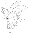
- a typical shoulder or glenohumeral joint is formed in a human body where the humerus 10 movably contacts the scapula 12.
- the scapula 12 includes a glenoid fossa 14 that forms a socket against which the head of the humerus 10 articulates.
- the scapula 12 includes cartilage 16 that facilitates such articulation.
- Beneath the cartilage is subchondral bone 18 that forms a wall of a glenoid vault 20 that defines a cavity which contains cancellous bone 22.
- the subchondral bone 18 that forms the glenoid vault 20 defines a glenoid rim 24 at a periphery of the glenoid vault 20 that is attached to the cartilage 16.
- the glenoid fossa 14 may become worn, especially at its posterior and/or superior portions thereby causing severe shoulder pain and limiting the range of motion of the patient's shoulder joint.
- a shoulder arthroplasty may be performed. Arthroplasty is the surgical replacement of one or more bone structures of a joint with one or more prostheses.
- the conventional glenoid component typically provides a generally laterally or outwardly facing generally concave bearing surface against which a prosthetic humeral head (or, alternatively, the spared natural humeral head in the case of a glenoid hemi-arthroplasty) may bear during operation of the joint.
- the conventional glenoid component typically also includes a generally medially or inwardly projecting stem for fixing the glenoid component in a cavity constructed by suitably resecting the glenoid fossa 14 and suitably resecting cancellous bone 22 from the glenoid vault 20.
- the goal of shoulder arthroplasty is to restore normal kinematics to the shoulder.
- known systems attempt to replicate the normal kinematics by carefully controlling the geometry of the articulating surfaces in the joint as well as the positioning of the prostheses in the bones in which the prostheses are implanted.
- the articulating surface of a humeral component is typically spherical and positioning of the humeral component is accomplished by using the anatomical neck of the humerus as the reference plane for reconstruction of the humeral head.
- the articulating surface of the glenoid is typically formed with a radius of curvature that is much larger than the radius of curvature of the humeral component.
- the increased radius of curvature of the glenoid articulating surface can be from 2-6 mm larger than the radius of curvature for the humeral component in these systems.
- the glenoid component is positioned in the geometric centre of the glenoid fossa.
- the geometric centre is established by generating a line from the most superior point of the glenoid rim to the most inferior point of the glenoid rim ("Saller's line").
- a second line is generated between the most posterior point of the glenoid rim and the most anterior point of the glenoid rim.
- the intersection of the two generated lines is considered to be the geometric centre of the area circumscribed by the glenoid rim.
- FIG. 2 depicts a sagittal view of the scapula 12.
- Saller's line 30 extends between the most superior point 32 of the glenoid rim 24 to the most inferior point 34 of the glenoid rim 24.
- a second line 36 extends from the most posterior point 38 of the glenoid rim 24 and the most anterior point 40 of the glenoid rim.
- the geometric centre 42 of the glenoid fossa 14 is located at the intersection of the line 36 and Saller's line 30.
- anterior, posterior, superior, and inferior are used with respect to the orientation of the scapula 12 as depicted in FIG. 2 .
- a guide pin is positioned through the glenoid fossa.
- a reamer is then used to shape the scapula to receive a glenoid component, typically by forming a cavity in the glenoid vault.
- a bore is drilled using the guide pin as a guide.
- the guide pin is then removed.
- a drill guide is introduced into the prepared cavity and additional bores are drilled for each of the offset pegs.
- a trial glenoid component is then implanted in the prepared cavity and, if the fit appears to be satisfactory, the trial is removed and a glenoid component is implanted in the prepared cavity.
- US-5489310 discloses a reamer which can be used to prepare a patient's glenoid to receive a glenoid component of a shoulder prosthesis.
- the reamer has a cannulated stem with a reamer head at one end having four cutting blades which extend downwardly from a central housing.
- Each of the cutting blades has a first cutting edge which tapers downwardly and inwardly towards the distal tip of the head, and a second cutting edge at the distal end of the first cutting edge.
- the second cutting edge extends parallel to the axis about which the reamer head rotates.
- Rotational drive can be imparted to the reamer to create a cavity which has a proximal portion which tapers inwardly and a distal cylindrical portion of constant diameter.
- US-6379386 discloses instruments which can be used to prepare a glenoid for implantation of a glenoid component.
- a first instrument is a reamer.
- a second instrument is a keel drill guide, which has holes formed in it for receiving drill bits. One of the holes is positioned centrally on the instrument and the others are positioned one on each side of the central hole.
- the present invention provides an instrumentation kit for use in preparing a shoulder to receive a glenoid component, as defined in claim 1.
- the kit provided by the invention can be used in a method of preparing a shoulder to receive a glenoid component includes accessing a glenoid of a shoulder, applying a rotational force to a combination device, forming a first bore in the glenoid with a rotating boring section of the combination device, forming a second bore in the glenoid at a location spaced apart from the first bore using a first drill guide defined by the combination device, and reaming a portion of the glenoid with a rotating reaming section of the combination device, in which forming a first bore and reaming a portion of the glenoid occur simultaneously.
- FIGs. 3-5 depict a glenoid component 100.
- the glenoid component 100 includes a body portion 102 including a spherical articulating surface 104 and an opposite bone contacting surface 106.
- An outer wall 108 extends away from the bone contacting surface 106 and defines an outer periphery of the body portion 102.
- the bone contacting surface 106 is generally convex.
- a finned centre peg 110 extends away from the nadir of the bone contacting surface 106 as viewed in FIG. 5 .
- Three offset pegs 112, 114, and 116 extend away from the bone contacting surface 106 at locations between the centre peg 110 and the outer wall 108.
- the nadir 118 of the spherical articulating surface 104 is located on the centerline 120 of the glenoid component 100.
- the glenoid component 100 is an integrally formed unit made from a durable biocompatible plastic or any other suitable durable biocompatible material.
- the glenoid component 100 may be made from a polyethylene.
- One particular polyethylene that is well suited for glenoid component 100 is a high molecular weight polyethylene, for example ultra-high molecular weight polyethylene ("UHMWPE").
- UHMWPE ultra-high molecular weight polyethylene
- One such UHMWPE is used in products sold as by Johnson & Johnson of New Brunswick, New Jersey under the trade mark MARATHON and is more fully described in US-6228900 and US-6281264 .
- the portions of the glenoid component 100 other than the articulating surface 104 may be made from a suitable biocompatible metal such as, for example, a cobalt chromium alloy, a stainless steel alloy, a titanium alloy, or any other suitable durable material.
- the articulating surface 104 is secured to the body portion 102 in any suitable manner.
- articulating surface 104 may be bonded to body portion 102, or articulating surface 104 could be made from polyethylene and compression melded to body portion 102.
- the articulating surface 104 may be glued to the body portion 102 by, for example, an adhesive.
- articulating surface 104 maybe mechanically interlocked to the body portion 102 by taper locking or otherwise press-fitting the articulating surface 104 into the body 102 and the body 102 may include any other suitable interlocking features, for example, rib(s), lip(s), detent(s), and/or other protrusion(s) and mating groove(s), channel(s), or indent(s) (not shown).
- one or more of the outer wall 108, the bone contacting surface 106, the centre peg 110 and the offset pegs 112, 114, and 116 may include a porous coating to facilitate bone in-growth into the glenoid component 100.
- the porous coating may be any suitable porous coating and may for example be like the one used in products sold by Johnson & Johnson of New Brunswick, New Jersey under the trade mark POROCOAT, as described in US-3855638 .
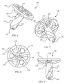
- a combination device 130 includes a drive section 132, a body section 134, and a drill or boring section 136.
- the drive section 132 in this construction is a hexagonally shaped bore defined in the body section 134.
- a number of reaming fins 140 extend from the lower central portion of the body section 134 toward the drill section 136.
- the reaming fins 140 curve proximally and outwardly from the lower central portion of the body section 134 to the outer periphery of the body section 134.
- the reaming fins 140 include an arcuate leading edge 142.
- the body section 134 defines a number of through-holes at locations between adjacent reaming fins 140.
- the through-holes in the construction of FIGs. 6-9 include three drill guides 146 and three ports 148.
- the drill section 136 extends away from the body section 134 to a distal tip 150.
- Two flutes 152 and 154 extend helically about the drill section 136 between the body section 134 and the distal tip 150.
- a guide bore 156 extends from the distal tip 150 to the drive section 132.
- a kit may include one or more combination devices 130 along with various instrumentation to facilitate use of the combination device 130.
- FIG. 10 depicts a power extension 160 that may be included in the kit.
- the power extension 160 includes a power receiving portion 162 and a power transfer portion 164.
- the power receiving portion 162 is sized and configured to couple with a power tool and includes a pair of opposing power receiving flats 166 and a pair of coupling grooves 168 and 170 which extend about the power receiving portion 162 between the power receiving flats 166.
- the power transfer portion 164 is shaped to be complimentary to the drive section 132. In the construction of FIGs. 10 and 11 , the power transfer portion 164 is thus a hexagonally shaped protrusion sized to fit within the drive section 132.
- a guide bore 172 extends from the distal tip of the power transfer portion 164 to the proximal end of the power receiving portion 162.
- the power transfer portion 164 is aligned with the drive section 132 as shown in FIG. 12 .
- the combination device 130 with the power extension 160 are then moved toward each other such that the power transfer portion 164 enters into the drive section 132 resulting in the configuration of FIG. 13 .
- the guide bore 156 of the combination device 130 is aligned with the guide bore 172 of the power extension 160.
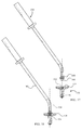
- FIGs. 14-16 depict a manual extension 180 that may also be included in the kit.
- the manual extension 180 includes a handle portion 182 and a power transfer portion 184.
- the handle portion 182 is sized and configured to be easily gripped and defines a first axis 186.
- the power transfer portion 184 includes a hexagonal protuberance 188 shaped to be complimentary to the drive section 132.
- the power transfer portion 184 defines a second axis 190.
- the second axis 190 forms an angle 192 of about 145 degrees with the first axis 186.
- a guide bore 194 extends from the distal tip of the power transfer portion 184 along the second axis 190.
- the power transfer portion 184 is aligned with the drive section 132 as shown in FIG. 17 .
- the combination device 130 and the manual extension 180 are then moved toward each other such that the hexagonal protuberance 188 enters into the drive section 132 resulting in the configuration of FIG. 18 .
- the guide bore 156 of the combination device 130 is aligned with the guide bore 194 of the manual extension 180.
- the angle 192 (see FIG. 14 ) between the handle portion 182 and the power transfer portion 184 allows a user to easily see the guide bore 194, thereby assisting in alignment of the power transfer portion 184 with the drive section 132 or, as discussed in more detail below, with a guide wire extending through the guide bore 156.
- the angle192 further provides a mechanical advantage in maintaining the combination device 130 in a desired location as also discussed below.
- a kit including the combination device 130, the power extension 160, and the manual extension 180 may be used in preparing a shoulder to receive a glenoid component such as glenoid component 100 in accordance with a procedure 200 depicted in FIG. 19 .
- a scapula is accessed at block 202 in accordance with a desired surgical approach.
- a guide wire which may be provided in a kit along with other instrumentation used in the procedure 200, is positioned on the scapula. Positioning of the guide wire may be computer aided. In one construction, the guide wire is positioned based upon identification of the centre of an inferior glenoid circle. By way of example, FIG.
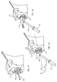
- FIG. 20 depicts a guide wire 206 implanted into a glenoid 614 of the scapula 612.
- the guide wire 206 has been positioned with the aid of a guide plate 208 and a guide plate manipulator 210.
- a combination device 130 is positioned with the guide bore 156 aligned with the guide wire.
- the combination device 130 is then moved toward the guide wire and at block 212 the guide wire is used to guide the combination device 130 to a location adjacent to the glenoid 14 of the scapula12 as depicted in FIG. 21 .
- a power extension 160 is coupled to the combination device 130 substantially in the manner described above. Since the guide wire 206 extends through the guide bore 156 of the combination device 130, however, coupling of the power extension 160 to the combination device 130 begins by aligning the guide bore 172 of the power extension 160 with the guide wire 206. The guide wire 206 thus guides the power extension 160 to the combination device 130. Some rotation of the power extension 160 may be required to align the power transfer portion 164 with the drive section 132 of the combination device 130 to allow coupling of the power extension 160 with the combination device 130. The resulting configuration is depicted in FIG. 22 .
- a rotary tool (not shown) is then coupled to the combination device 130 at block 216.
- a rotary tool may be directly coupled to the combination device 130.
- the power extension 160 is coupled to the combination device 130 as described above.
- the rotary tool is coupled to the power receiving portion 162 of the power extension 160 so as to be indirectly coupled to the combination device 130.
- the power tool is deenergized and disconnected at block 220.
- the size of the drill section 132 both in length and diameter, is selected to be complimentary to the size of the centre peg 110 of the glenoid component 100.
- the bore formed by the drill section is sized to receive the finned centre peg 110.
- the power extension 160 is disconnected at block 222, resulting in the configuration of FIG. 24 .
- the manual extension 180 is coupled to the combination device 130 substantially in the manner described above. Since the guide wire 206 extends through the guide bore 156 of the combination device 130, however, coupling of the manual extension 180 to the combination device 130 begins by aligning the guide bore 190 of the manual extension 180 with the guide wire 206. The guide wire 206 thus guides the manual extension 180 to the combination device 130. Some rotation of the manual extension 180 may be required to align the hexagonal protuberance 188 of the manual extension 180 with the drive section 132 of the combination device 130 to allow coupling of the manual extension 180 with the combination device 130. The resulting configuration is depicted in FIG. 25 .
- the manual extension 180 may be used to align the combination device 130 at block 226 as explained with reference to FIG. 25 .
- the handle portion 182 may be rotated about the axis 2288 defined by the guide wire 206. Rotation of the handle portion 182 about the axis 228 causes rotation of the combination device 130 about the axis 228.
- the curvature of the manual extension 180 resulting from the angle 192 provides a surgeon with a relatively unobstructed view of the combination device 130. Accordingly, the surgeon may view the reamed surface of the glenoid 14 through the drill guides 146. This allows a surgeon to view the location in the shoulder 12 at which the offset fixation pegs 112, 114, and 116 of the glenoid component 100 will be anchored.
- the surgeon may orient the combination device 130 such that each of the drill guides 146 is aligned with portions of the shoulder that can provide a good anchor for the offset fixation pegs 112, 114, and 116.
- FIG. 26 depicts a drill bit 232 positioned in a drill guide 146 of the combination device 130.
- the manual extension 180 may be used to steady the combination device 130 during the drilling process.
- the offset of the handle portion 182 from the axis 228 provided by the angle 192 results in a mechanical advantage in maintaining the combination device 130 at the desired orientation.
- Blocks 226 and 30 may be repeated as desired to form additional holes.
- the combination device 130 is removed at block 234.
- the manual extension 180 may be used to aid in removal of the combination device 130.
- the glenoid component is implanted.
- the glenoid component 100 has a lower bone contacting surface 106 shaped complimentary to the reaming cross-section of the reaming fins 140.
- the lower bone contacting surface 106 is curved complimentary to the distal curve of the reaming fins 140.
- the reaming fins 140 may be configured to produce a flat bottomed area if a glenoid component with a flat lower bone contacting surface is used. Accordingly, a kit may include different combination devices with differently shaped reaming cross-sections.
- the combination device 130 and the procedure 200 maybe used in combination with various of the devices and procedures disclosed in the related applications identified above.
- the combination device 130 is useful in implanting a circular glenoid device at the centre of the inferior glenoid circle
- the combination device 130 maybe used to implant other glenoid components, including non-circular glenoid components, at any desired location in a glenoid.
- the diameter of the reaming cross-section of the combination device 130 is selected to match the largest diameter of a glenoid component.
- a kit may include one or more combination devices 130 of the same reaming diameter
- a kit may alternatively include a number of combination devices with differently sized reaming diameters.
Claims (10)
- Kit d'instrumentation pour son utilisation dans la préparation d'une épaule à recevoir un composant glénoïde comprenant :au moins un dispositif de combinaison (130) qui possède une partie corps (134), et qui comprend :- une section de forage (136) qui s'étend distalement de la partie corps et est conçue pour pivoter afin de former un premier canal dans un glénoïde d'une épaule,- une section d'entraînement (132) qui est définie par la partie corps et est ainsi fonctionnellement raccordée à la section de forage, la section d'entraînement étant conçue pour recevoir une force rotative, et- une section d'alésage (140) qui est positionnée proximalement de la section de forage et s'étend distalement à partir de la partie corps, la section d'alésage étant fonctionnellement raccordée à la section d'entraînement, et conçue pour aléser en rotation une partie du glénoïde,dans lequel la section d'alésage et la section de forage sont positionnées l'une par rapport à l'autre de telle sorte que lorsque le dispositif de combinaison est positionné contre le glénoïde et que la force rotative est appliquée à la section d'entraînement, la section de forage forme par rotation le premier canal dans le glénoïde et la section d'alésage alèse simultanément par rotation une partie du glénoïde adjacente au premier canal,caractérisé en ce que le dispositif de combinaison comprend au moins un guide-foret (146) qui est défini par la partie corps et qui est conçu pour guider une mèche de foret et positionné de manière à guider la mèche de foret pour former un second canal dans l'épaule au niveau d'un emplacement espacé du premier canal.
- Kit d'instrumentation selon la revendication 1, dans lequel la section d'alésage comprend une pluralité d'ailettes d'alésage (140) s'étendant distalement à partir de la partie corps (134), chacune des ailettes de la pluralité d'ailettes d'alésage définissant un bord avant arqué (142).
- Kit d'instrumentation selon la revendication 2, dans lequel le au moins un guide-foret comprend une pluralité de guides-forets circulaires (146), chacun des guides-forets de la pluralité de guides-forets circulaires étant positionné de telle sorte que lorsqu'une mèche de foret est déployée à travers l'un quelconque des guides-forets de la pluralité de guides-forets circulaires, la mèche de foret s'étend entre deux ailettes d'alésages respectives de la pluralité d'ailettes d'alésage (140).
- Kit d'instrumentation selon la revendication 3, comprenant en outre une pluralité d'orifices (148) s'étendant d'une surface distale de la partie corps (134) à une surface proximale de la partie corps.
- Kit d'instrumentation selon la revendication 1, le dispositif de combinaison comprenant en outre un canal de guidage (156) s'étendant d'une pointe distale (150) de la section de forage (136) à la section d'entraînement (132).
- Kit d'instrumentation selon la revendication 1, comprenant en outre en outre une extension d'alimentation (160), l'extension d'alimentation comprenant une première partie de couplage (164) conçue pour se coupler à la section d'entraînement (132) pour transférer la force rotative à la section d'entraînement, et une seconde partie de couplage (162) conçue pour se coupler à un outil électrique rotatif.
- Kit d'instrumentation selon la revendication 6, comprenant en outre en outre une extension manuelle (180), l'extension manuelle comprenant une première partie d'extrémité avec une partie de couplage (184) conçue pour se coupler à la section d'entraînement pour transférer la force rotative à la section d'entraînement, et un manche (182) situé au niveau d'une seconde partie d'extrémité.
- Kit d'instrumentation selon la revendication 7, dans lequel la première partie d'extrémité (184) de l'extension manuelle (180) définit un premier axe (186) et la seconde partie d'extrémité de l'extension manuelle définit un second axe (190), le premier axe et le second axe formant un angle (192) autre que 180 degrés.
- Kit d'instrumentation selon la revendication 8, dans lequel :le dispositif de combinaison comprend en outre un canal de guidage de dispositif de combinaison (156) s'étendant d'une pointe distale de la section de forage (136) à la section d'entraînement (132),l'extension d'alimentation (160) comprend en outre un canal de guidage d'alimentation (172) conçu pour s'aligner sur le canal de guidage de dispositif de combinaison lorsque l'extension d'alimentation est couplée au dispositif de combinaison, etl'extension manuelle (180) comprend en outre un canal de guidage manuel (194) conçu pour s'aligner sur le canal de guidage de dispositif de combinaison lorsque l'extension manuelle est couplée au dispositif de combinaison.
- Kit d'instrumentation selon la revendication 7, dans lequel le au moins un dispositif de combinaison comprend une pluralité de dispositifs de combinaison, chacun des dispositifs de combinaison de la pluralité de dispositifs de combinaison définissant un diamètre d'alésage différent du diamètre d'alésage d'un autre dispositif de combinaison de la pluralité de dispositifs de combinaison.
Applications Claiming Priority (2)
| Application Number | Priority Date | Filing Date | Title |
|---|---|---|---|
| US13/051,026 US9820758B2 (en) | 2011-03-18 | 2011-03-18 | Combination reamer/drill bit for shoulder arthoplasty |
| PCT/US2012/029016 WO2012129018A1 (fr) | 2011-03-18 | 2012-03-14 | Combinaison alésoir/foret pour arthroplastie de l'épaule |
Publications (3)
| Publication Number | Publication Date |
|---|---|
| EP2685905A1 EP2685905A1 (fr) | 2014-01-22 |
| EP2685905A4 EP2685905A4 (fr) | 2014-09-10 |
| EP2685905B1 true EP2685905B1 (fr) | 2016-06-01 |
Family
ID=46829052
Family Applications (1)
| Application Number | Title | Priority Date | Filing Date |
|---|---|---|---|
| EP12760199.5A Active EP2685905B1 (fr) | 2011-03-18 | 2012-03-14 | Combinaison alésoir/foret pour arthroplastie de l'épaule |
Country Status (7)
| Country | Link |
|---|---|
| US (4) | US9820758B2 (fr) |
| EP (1) | EP2685905B1 (fr) |
| JP (1) | JP6046108B2 (fr) |
| CN (1) | CN103702618B (fr) |
| AU (1) | AU2012231297B2 (fr) |
| ES (1) | ES2590003T3 (fr) |
| WO (1) | WO2012129018A1 (fr) |
Families Citing this family (29)
| Publication number | Priority date | Publication date | Assignee | Title |
|---|---|---|---|---|
| FR2967046A1 (fr) | 2010-11-10 | 2012-05-11 | Tornier Sa | Fraiseuse orthopedique de preparation osseuse, en particulier de preparation glenoidienne |
| EP2564792A1 (fr) * | 2011-09-02 | 2013-03-06 | Episurf Medical AB | Kit chirurgical modulaire pour la réparation de cartilages |
| US11000387B2 (en) | 2011-09-02 | 2021-05-11 | Episurf Ip-Management Ab | Implant for cartilage repair |
| US10603049B2 (en) | 2011-09-02 | 2020-03-31 | Episurf Ip-Management Ab | Implant specific drill bit in surgical kit for cartilage repair |
| US9408613B2 (en) * | 2011-12-13 | 2016-08-09 | Biomet Manufacturing, Llc | Glenoid reamer |
| CA3072704C (fr) | 2012-03-28 | 2022-03-22 | Orthosoft Ulc | Chirurgie d'implantation glenoide utilisant une instrumentation specifique au patient |
| US20140081270A1 (en) * | 2012-09-14 | 2014-03-20 | Depuy Products, Inc. | Bone graft shaper for reverse glenoid |
| US9320527B2 (en) * | 2013-01-18 | 2016-04-26 | Biomet Manufacturing, Llc | Quick-connect anti-rotation peg/drill bit component |
| WO2015018921A1 (fr) | 2013-08-08 | 2015-02-12 | Universiteit Gent | Instrument chirurgical de guidage |
| US10117657B2 (en) * | 2014-03-21 | 2018-11-06 | Arthrex, Inc. | Nautilus glenoid reamer |
| US10575968B2 (en) | 2014-05-16 | 2020-03-03 | Howmedica Osteonics Corp. | Guides for fracture system |
| US9681960B2 (en) | 2014-05-16 | 2017-06-20 | Howmedica Osteonics Corp. | Guides for fracture system |
| US10028838B2 (en) | 2014-06-30 | 2018-07-24 | Tornier, Inc. | Augmented glenoid components and devices for implanting the same |
| US11234826B2 (en) | 2014-06-30 | 2022-02-01 | Howmedica Osteonics Corp. | Augmented glenoid components and devices for implanting the same |
| EP3166540B1 (fr) | 2014-07-09 | 2019-06-19 | Episurf IP-Management AB | Implant d'articulation chirurgical |
| WO2016004991A1 (fr) | 2014-07-09 | 2016-01-14 | Episurf Ip-Management Ab | Implant personnalisé pour la réparation de cartilage et procédé de conception correspondant |
| US20160045207A1 (en) | 2014-08-14 | 2016-02-18 | Biomet Manufacturing, Llc | Flexible bone reamer |
| US9955984B2 (en) * | 2015-01-12 | 2018-05-01 | Biomet Manufacturing, Llc | Augmented glenoid and method for preparation |
| JP2016154807A (ja) * | 2015-02-26 | 2016-09-01 | 国立大学法人東北大学 | 臨床用補助器具 |
| US10016288B2 (en) | 2015-07-23 | 2018-07-10 | DePuy Synthes Products, Inc. | Shoulder arthroplasty system with combination humeral sizer, trial, and guide |
| US10335169B2 (en) | 2015-09-14 | 2019-07-02 | Symmetry Medical Manufacturing, Inc. | Angled orthopaedic driver |
| WO2018022227A1 (fr) | 2016-07-28 | 2018-02-01 | Tornier, Inc. | Composant d'ancrage de prothèse sans tige |
| US10881514B2 (en) * | 2017-05-19 | 2021-01-05 | Biomet Manufacturing, Llc | Implant assembly tools and methods |
| US10610243B2 (en) | 2017-10-09 | 2020-04-07 | Acumed Llc | System and method for installing a bicortical implant in bone |
| EP3849437A4 (fr) * | 2018-09-16 | 2022-07-27 | Ignite Orthopedics LLC | Alésoir pour os et procédés d'utilisation |
| AU2020204539A1 (en) | 2019-07-12 | 2021-01-28 | Howmedica Osteonics Corp. | Augmented glenoid design |
| US11426285B2 (en) | 2019-09-05 | 2022-08-30 | Howmedica Osteonics Corp. | Truss glenoid augment |
| AU2021200854A1 (en) | 2020-03-03 | 2021-09-16 | Howmedica Osteonics Corp. | Glenoid implant with additively manufactured fixation posts |
| CN113384338B (zh) * | 2020-03-11 | 2023-02-24 | 西安交通大学医学院第一附属医院 | 一种跟骨载距突螺钉自动导向装置 |
Family Cites Families (67)
| Publication number | Priority date | Publication date | Assignee | Title |
|---|---|---|---|---|
| US2487203A (en) | 1946-07-17 | 1949-11-08 | Arthur L Wilber | Flexible drive for drills |
| CA962806A (en) | 1970-06-04 | 1975-02-18 | Ontario Research Foundation | Surgical prosthetic device |
| JPS5123336B1 (fr) | 1972-12-28 | 1976-07-16 | ||
| GB1544403A (en) | 1975-01-31 | 1979-04-19 | Nat Res Dev | Endoprosthetic bone joint devices |
| US4964865A (en) | 1988-02-03 | 1990-10-23 | Intermedics Orthopedics, Inc. | Glenoid prosthesis and method of use |
| US5080673A (en) | 1988-02-03 | 1992-01-14 | Intermedics Orthopedics, Inc. | Glenoid prosthesis and method of use |
| US5030219A (en) * | 1990-01-22 | 1991-07-09 | Boehringer Mannheim Corporation | Glenoid component installation tools |
| US5180384A (en) * | 1991-02-08 | 1993-01-19 | Mikhail Michael W E | Method for implanting a patellar prosthesis |
| US5324295A (en) | 1992-04-24 | 1994-06-28 | Shapiro Michael R | Drill guide for surgical pins |
| FR2704747B1 (fr) | 1993-05-06 | 1995-07-21 | Medinov Sa | Support destiné à recevoir un organe glénoïdien. |
| US5489310A (en) * | 1994-06-27 | 1996-02-06 | Mikhail; W. E. Michael | Universal glenoid shoulder prosthesis and method for implanting |
| CA2166450C (fr) | 1995-01-20 | 2008-03-25 | Ronald Salovey | Polyethylene de masse moleculaire tres elevee, reticule chimiquement, pour articulations artificielles chez l'homme |
| US6228900B1 (en) | 1996-07-09 | 2001-05-08 | The Orthopaedic Hospital And University Of Southern California | Crosslinking of polyethylene for low wear using radiation and thermal treatments |
| US5800551A (en) | 1997-03-10 | 1998-09-01 | Biomet, Inc. | Apparatus and method for shoulder arthroplasty |
| JP3764253B2 (ja) | 1997-07-14 | 2006-04-05 | 鬼怒川ゴム工業株式会社 | 自動車の緊急脱出装置 |
| US6379386B1 (en) | 1997-09-09 | 2002-04-30 | Stryker Technologies Corporation | Anatomic glenoid shoulder prosthesis together with methods and tools for implanting same |
| JPH11127256A (ja) | 1997-10-23 | 1999-05-11 | Matsushita Electric Ind Co Ltd | 電子会議装置 |
| US5919195A (en) | 1998-01-20 | 1999-07-06 | Johnson & Johnson Professional, Inc. | Oblong acetabular component instrumentation |
| US6494913B1 (en) | 1998-03-17 | 2002-12-17 | Acumed, Inc. | Shoulder prosthesis |
| US6010535A (en) | 1998-04-30 | 2000-01-04 | Shah; Mrugesh K. | Joint replacement system |
| US6045302A (en) | 1999-03-04 | 2000-04-04 | Orr; Pat | Drill bit retriever device |
| CH693446A5 (fr) | 1999-06-10 | 2003-08-15 | Precimed Sa | Outil à main muni d'une transmission à cardan. |
| KR100341576B1 (ko) | 1999-06-28 | 2002-06-22 | 박종섭 | 반도체메모리장치의 파이프데이터 입력 제어 방법 및 장치 |
| US6245074B1 (en) | 1999-09-01 | 2001-06-12 | Bristol-Myers Squibb Co. | Orthopaedic glenoid reamer |
| US20070055249A1 (en) * | 2003-06-20 | 2007-03-08 | Jensen David G | Bone plates with intraoperatively tapped apertures |
| US6364910B1 (en) | 2001-07-11 | 2002-04-02 | Biomet, Inc. | Method and apparatus for use of a glenoid component |
| US6783549B1 (en) | 2001-07-27 | 2004-08-31 | Biomet, Inc. | Modular humeral head resurfacing system |
| US6699289B2 (en) | 2001-12-31 | 2004-03-02 | Depuy Orthopaedics, Inc. | Augmented glenoid component having an interrupted surface and associated method for securing the augmented glenoid component to a glenoid surface of a scapula |
| US6679916B1 (en) | 2002-04-29 | 2004-01-20 | Mark A. Frankle | Shoulder prosthesis system |
| US8062376B2 (en) | 2002-07-10 | 2011-11-22 | Biomet Manufacturing Corp. | Shoulder implant assembly |
| US7217271B2 (en) | 2002-09-13 | 2007-05-15 | Symmetry Medical, Inc. | Orthopaedic reamer driver for minimally invasive surgery |
| US7329284B2 (en) | 2002-09-27 | 2008-02-12 | Depuy Products, Inc. | Concave resurfacing prosthesis |
| US7001392B2 (en) * | 2003-01-29 | 2006-02-21 | Howmedica Osteonics Corp. | Apparatus and method for preparing bone for antirotational implantation of an orthopedic endoprosthesis |
| US20070043376A1 (en) | 2003-02-21 | 2007-02-22 | Osteobiologics, Inc. | Bone and cartilage implant delivery device |
| US8366713B2 (en) | 2003-03-31 | 2013-02-05 | Depuy Products, Inc. | Arthroplasty instruments and associated method |
| US7338498B2 (en) | 2003-03-31 | 2008-03-04 | Depuy Products, Inc. | Prosthetic implant, trial and associated method |
| FR2855743B1 (fr) | 2003-06-06 | 2006-02-10 | Biotechni | Insert pour cupule d'implant cotyloidien pour prothese articulaire, implant cotyloidien et prothese articulaire |
| WO2005016123A2 (fr) | 2003-08-11 | 2005-02-24 | Chudik Steven C M D | Dispositifs et methodes pour remplacement de l'epaule |
| GB2406278B (en) | 2003-09-24 | 2007-08-29 | Biomet Merck Ltd | A reamer |
| US7294133B2 (en) | 2004-06-03 | 2007-11-13 | Zimmer Technology, Inc. | Method and apparatus for preparing a glenoid surface |
| US8303665B2 (en) | 2004-06-15 | 2012-11-06 | Tornier Sas | Glenoidal component, set of such components and shoulder prosthesis incorporating such a glenoidal component |
| US7927335B2 (en) * | 2004-09-27 | 2011-04-19 | Depuy Products, Inc. | Instrument for preparing an implant support surface and associated method |
| US7892287B2 (en) | 2004-09-27 | 2011-02-22 | Depuy Products, Inc. | Glenoid augment and associated method |
| DE102004053606A1 (de) | 2004-11-05 | 2006-05-11 | Plus Orthopedics Ag | Glenoidprothese |
| US8007538B2 (en) | 2005-02-25 | 2011-08-30 | Shoulder Innovations, Llc | Shoulder implant for glenoid replacement |
| US8778028B2 (en) | 2005-02-25 | 2014-07-15 | Shoulder Innovations, Inc. | Methods and devices for less invasive glenoid replacement |
| CA2604144A1 (fr) | 2005-04-11 | 2006-10-19 | Impliant Ltd. | Insertion de protheses spinales anterieures et posterieures |
| US20070038302A1 (en) | 2005-08-15 | 2007-02-15 | Biomet Manufacturing Corp. | Method and apparatus for the preparation of an inlaid glenoid |
| US7959680B2 (en) | 2006-02-02 | 2011-06-14 | Biomet Manufacturing Corp. | Method and apparatus for performing a shoulder implant procedure |
| US8425614B2 (en) | 2006-03-20 | 2013-04-23 | Biomet Manufacturing Corp. | Modular center pegged glenoid |
| US20070251356A1 (en) | 2006-04-26 | 2007-11-01 | Tribby Jerry W | Spark plug wrench for confined spaces |
| US20070260321A1 (en) | 2006-05-02 | 2007-11-08 | Stchur Robert P | Conically-shaped glenoid implant with a prosthetic glenoid insert used in total shoulder arthroplasty and method |
| FR2902993B1 (fr) * | 2006-06-28 | 2008-09-05 | Trois S Ortho Sa | Prothese d'epaule et ensemble d'instruments pour l'implantation de cette prothese |
| US7604665B2 (en) | 2006-09-20 | 2009-10-20 | Depuy Products, Inc. | Glenoid component for shoulder arthroplasty |
| US8157866B2 (en) * | 2007-11-05 | 2012-04-17 | Biomet Manufacturing Corp. | Method and apparatus for performing a less invasive shoulder procedure |
| WO2009105819A1 (fr) | 2008-02-27 | 2009-09-03 | Titanium Truck Technologies Pty Ltd | Élément de suspension pour un bloc-essieu de planche à roulettes |
| US20090270993A1 (en) | 2008-04-28 | 2009-10-29 | Robin Maisonneuve | Orientation feature on eccentric glenosphere |
| US8241365B2 (en) | 2008-12-23 | 2012-08-14 | Depuy Products, Inc. | Shoulder prosthesis with vault-filling structure having bone-sparing configuration |
| FR2940607B1 (fr) | 2008-12-29 | 2012-04-06 | Didier Capon | Implant glenoidien comprenant une cupule destinee a cooperer avec une tete humerale prothetique |
| FR2944694B1 (fr) | 2009-04-22 | 2012-05-18 | Tornier Sa | Dispositif de fixation de la glene d'un composant articulaire glenoidien pour prothese d'epaule, ainsi que prothese d'epaule correspondante |
| AP2011006005A0 (en) * | 2009-06-24 | 2011-12-31 | Custom Med Orthopaedics Proprietary Ltd | A positioning guide and a bone cutting guide system. |
| US9549820B2 (en) | 2009-06-25 | 2017-01-24 | Zimmer, Inc. | Glenoid implant with synthetic labrum |
| EP2451365B1 (fr) | 2009-07-10 | 2015-07-01 | Kirk Promotion LTD. | Instrument d'articulation de la hanche |
| US8523867B2 (en) * | 2009-07-31 | 2013-09-03 | Zimmer Gmbh | Orthopaedic reamer |
| US8480750B2 (en) | 2010-11-24 | 2013-07-09 | DePuy Synthes Products, LLC | Modular glenoid prosthesis |
| US8764836B2 (en) | 2011-03-18 | 2014-07-01 | Lieven de Wilde | Circular glenoid method for shoulder arthroplasty |
| US10039556B2 (en) | 2011-11-10 | 2018-08-07 | David Michael Burt | Arthroscopic total shoulder arthroplasty |
-
2011
- 2011-03-18 US US13/051,026 patent/US9820758B2/en active Active
-
2012
- 2012-03-14 EP EP12760199.5A patent/EP2685905B1/fr active Active
- 2012-03-14 CN CN201280023890.7A patent/CN103702618B/zh active Active
- 2012-03-14 AU AU2012231297A patent/AU2012231297B2/en active Active
- 2012-03-14 WO PCT/US2012/029016 patent/WO2012129018A1/fr unknown
- 2012-03-14 JP JP2014501145A patent/JP6046108B2/ja active Active
- 2012-03-14 ES ES12760199.5T patent/ES2590003T3/es active Active
-
2017
- 2017-10-25 US US15/793,229 patent/US10779842B2/en active Active
-
2020
- 2020-08-25 US US17/002,389 patent/US11369390B2/en active Active
-
2022
- 2022-06-08 US US17/835,692 patent/US11903594B2/en active Active
Also Published As
| Publication number | Publication date |
|---|---|
| US20200383691A1 (en) | 2020-12-10 |
| JP2014516265A (ja) | 2014-07-10 |
| CN103702618A (zh) | 2014-04-02 |
| EP2685905A1 (fr) | 2014-01-22 |
| US10779842B2 (en) | 2020-09-22 |
| US20220296258A1 (en) | 2022-09-22 |
| US11369390B2 (en) | 2022-06-28 |
| AU2012231297A1 (en) | 2013-10-17 |
| JP6046108B2 (ja) | 2016-12-14 |
| US20120239042A1 (en) | 2012-09-20 |
| US11903594B2 (en) | 2024-02-20 |
| US20180042621A1 (en) | 2018-02-15 |
| US9820758B2 (en) | 2017-11-21 |
| AU2012231297B2 (en) | 2016-06-16 |
| ES2590003T3 (es) | 2016-11-17 |
| EP2685905A4 (fr) | 2014-09-10 |
| CN103702618B (zh) | 2016-12-14 |
| WO2012129018A1 (fr) | 2012-09-27 |
Similar Documents
| Publication | Publication Date | Title |
|---|---|---|
| US11369390B2 (en) | Method using a combination reamer/drill bit for shoulder arthroplasty | |
| US11298141B2 (en) | Method of using a combination driver/anti-rotation handle for shoulder arthroplasty | |
| US9445911B2 (en) | Bone preparation tool kit and associated method | |
| EP2316387B1 (fr) | Guide de découpe pour une utilisation dans une procédure de remplacement d'articulation | |
| AU2018217341B2 (en) | Combination driver/anti-rotation handle for shoulder arthroplasty |
Legal Events
| Date | Code | Title | Description |
|---|---|---|---|
| PUAI | Public reference made under article 153(3) epc to a published international application that has entered the european phase |
Free format text: ORIGINAL CODE: 0009012 |
|
| 17P | Request for examination filed |
Effective date: 20130916 |
|
| AK | Designated contracting states |
Kind code of ref document: A1 Designated state(s): AL AT BE BG CH CY CZ DE DK EE ES FI FR GB GR HR HU IE IS IT LI LT LU LV MC MK MT NL NO PL PT RO RS SE SI SK SM TR |
|
| DAX | Request for extension of the european patent (deleted) | ||
| REG | Reference to a national code |
Ref country code: DE Ref legal event code: R079 Ref document number: 602012019205 Country of ref document: DE Free format text: PREVIOUS MAIN CLASS: A61B0017000000 Ipc: A61B0017160000 |
|
| A4 | Supplementary search report drawn up and despatched |
Effective date: 20140807 |
|
| RIC1 | Information provided on ipc code assigned before grant |
Ipc: A61B 17/88 20060101ALI20140801BHEP Ipc: A61F 2/40 20060101ALI20140801BHEP Ipc: A61B 17/16 20060101AFI20140801BHEP Ipc: A61B 17/17 20060101ALI20140801BHEP |
|
| GRAP | Despatch of communication of intention to grant a patent |
Free format text: ORIGINAL CODE: EPIDOSNIGR1 |
|
| INTG | Intention to grant announced |
Effective date: 20160201 |
|
| GRAR | Information related to intention to grant a patent recorded |
Free format text: ORIGINAL CODE: EPIDOSNIGR71 |
|
| GRAS | Grant fee paid |
Free format text: ORIGINAL CODE: EPIDOSNIGR3 |
|
| GRAA | (expected) grant |
Free format text: ORIGINAL CODE: 0009210 |
|
| AK | Designated contracting states |
Kind code of ref document: B1 Designated state(s): AL AT BE BG CH CY CZ DE DK EE ES FI FR GB GR HR HU IE IS IT LI LT LU LV MC MK MT NL NO PL PT RO RS SE SI SK SM TR |
|
| INTG | Intention to grant announced |
Effective date: 20160427 |
|
| REG | Reference to a national code |
Ref country code: GB Ref legal event code: FG4D |
|
| REG | Reference to a national code |
Ref country code: CH Ref legal event code: EP Ref country code: CH Ref legal event code: NV Representative=s name: E. BLUM AND CO. AG PATENT- UND MARKENANWAELTE , CH Ref country code: AT Ref legal event code: REF Ref document number: 803358 Country of ref document: AT Kind code of ref document: T Effective date: 20160615 |
|
| REG | Reference to a national code |
Ref country code: IE Ref legal event code: FG4D |
|
| REG | Reference to a national code |
Ref country code: DE Ref legal event code: R096 Ref document number: 602012019205 Country of ref document: DE |
|
| REG | Reference to a national code |
Ref country code: NL Ref legal event code: FP |
|
| REG | Reference to a national code |
Ref country code: LT Ref legal event code: MG4D |
|
| PG25 | Lapsed in a contracting state [announced via postgrant information from national office to epo] |
Ref country code: FI Free format text: LAPSE BECAUSE OF FAILURE TO SUBMIT A TRANSLATION OF THE DESCRIPTION OR TO PAY THE FEE WITHIN THE PRESCRIBED TIME-LIMIT Effective date: 20160601 Ref country code: NO Free format text: LAPSE BECAUSE OF FAILURE TO SUBMIT A TRANSLATION OF THE DESCRIPTION OR TO PAY THE FEE WITHIN THE PRESCRIBED TIME-LIMIT Effective date: 20160901 Ref country code: LT Free format text: LAPSE BECAUSE OF FAILURE TO SUBMIT A TRANSLATION OF THE DESCRIPTION OR TO PAY THE FEE WITHIN THE PRESCRIBED TIME-LIMIT Effective date: 20160601 |
|
| REG | Reference to a national code |
Ref country code: AT Ref legal event code: MK05 Ref document number: 803358 Country of ref document: AT Kind code of ref document: T Effective date: 20160601 |
|
| REG | Reference to a national code |
Ref country code: ES Ref legal event code: FG2A Ref document number: 2590003 Country of ref document: ES Kind code of ref document: T3 Effective date: 20161117 |
|
| PG25 | Lapsed in a contracting state [announced via postgrant information from national office to epo] |
Ref country code: SE Free format text: LAPSE BECAUSE OF FAILURE TO SUBMIT A TRANSLATION OF THE DESCRIPTION OR TO PAY THE FEE WITHIN THE PRESCRIBED TIME-LIMIT Effective date: 20160601 Ref country code: GR Free format text: LAPSE BECAUSE OF FAILURE TO SUBMIT A TRANSLATION OF THE DESCRIPTION OR TO PAY THE FEE WITHIN THE PRESCRIBED TIME-LIMIT Effective date: 20160902 Ref country code: LV Free format text: LAPSE BECAUSE OF FAILURE TO SUBMIT A TRANSLATION OF THE DESCRIPTION OR TO PAY THE FEE WITHIN THE PRESCRIBED TIME-LIMIT Effective date: 20160601 Ref country code: RS Free format text: LAPSE BECAUSE OF FAILURE TO SUBMIT A TRANSLATION OF THE DESCRIPTION OR TO PAY THE FEE WITHIN THE PRESCRIBED TIME-LIMIT Effective date: 20160601 Ref country code: HR Free format text: LAPSE BECAUSE OF FAILURE TO SUBMIT A TRANSLATION OF THE DESCRIPTION OR TO PAY THE FEE WITHIN THE PRESCRIBED TIME-LIMIT Effective date: 20160601 |
|
| PG25 | Lapsed in a contracting state [announced via postgrant information from national office to epo] |
Ref country code: IS Free format text: LAPSE BECAUSE OF FAILURE TO SUBMIT A TRANSLATION OF THE DESCRIPTION OR TO PAY THE FEE WITHIN THE PRESCRIBED TIME-LIMIT Effective date: 20161001 Ref country code: CZ Free format text: LAPSE BECAUSE OF FAILURE TO SUBMIT A TRANSLATION OF THE DESCRIPTION OR TO PAY THE FEE WITHIN THE PRESCRIBED TIME-LIMIT Effective date: 20160601 Ref country code: RO Free format text: LAPSE BECAUSE OF FAILURE TO SUBMIT A TRANSLATION OF THE DESCRIPTION OR TO PAY THE FEE WITHIN THE PRESCRIBED TIME-LIMIT Effective date: 20160601 Ref country code: SK Free format text: LAPSE BECAUSE OF FAILURE TO SUBMIT A TRANSLATION OF THE DESCRIPTION OR TO PAY THE FEE WITHIN THE PRESCRIBED TIME-LIMIT Effective date: 20160601 Ref country code: EE Free format text: LAPSE BECAUSE OF FAILURE TO SUBMIT A TRANSLATION OF THE DESCRIPTION OR TO PAY THE FEE WITHIN THE PRESCRIBED TIME-LIMIT Effective date: 20160601 |
|
| REG | Reference to a national code |
Ref country code: FR Ref legal event code: PLFP Year of fee payment: 6 |
|
| PG25 | Lapsed in a contracting state [announced via postgrant information from national office to epo] |
Ref country code: PT Free format text: LAPSE BECAUSE OF FAILURE TO SUBMIT A TRANSLATION OF THE DESCRIPTION OR TO PAY THE FEE WITHIN THE PRESCRIBED TIME-LIMIT Effective date: 20161003 Ref country code: SM Free format text: LAPSE BECAUSE OF FAILURE TO SUBMIT A TRANSLATION OF THE DESCRIPTION OR TO PAY THE FEE WITHIN THE PRESCRIBED TIME-LIMIT Effective date: 20160601 Ref country code: AT Free format text: LAPSE BECAUSE OF FAILURE TO SUBMIT A TRANSLATION OF THE DESCRIPTION OR TO PAY THE FEE WITHIN THE PRESCRIBED TIME-LIMIT Effective date: 20160601 Ref country code: PL Free format text: LAPSE BECAUSE OF FAILURE TO SUBMIT A TRANSLATION OF THE DESCRIPTION OR TO PAY THE FEE WITHIN THE PRESCRIBED TIME-LIMIT Effective date: 20160601 |
|
| REG | Reference to a national code |
Ref country code: DE Ref legal event code: R097 Ref document number: 602012019205 Country of ref document: DE |
|
| PLBE | No opposition filed within time limit |
Free format text: ORIGINAL CODE: 0009261 |
|
| STAA | Information on the status of an ep patent application or granted ep patent |
Free format text: STATUS: NO OPPOSITION FILED WITHIN TIME LIMIT |
|
| 26N | No opposition filed |
Effective date: 20170302 |
|
| PG25 | Lapsed in a contracting state [announced via postgrant information from national office to epo] |
Ref country code: SI Free format text: LAPSE BECAUSE OF FAILURE TO SUBMIT A TRANSLATION OF THE DESCRIPTION OR TO PAY THE FEE WITHIN THE PRESCRIBED TIME-LIMIT Effective date: 20160601 Ref country code: DK Free format text: LAPSE BECAUSE OF FAILURE TO SUBMIT A TRANSLATION OF THE DESCRIPTION OR TO PAY THE FEE WITHIN THE PRESCRIBED TIME-LIMIT Effective date: 20160601 |
|
| PG25 | Lapsed in a contracting state [announced via postgrant information from national office to epo] |
Ref country code: MC Free format text: LAPSE BECAUSE OF FAILURE TO SUBMIT A TRANSLATION OF THE DESCRIPTION OR TO PAY THE FEE WITHIN THE PRESCRIBED TIME-LIMIT Effective date: 20160601 |
|
| PG25 | Lapsed in a contracting state [announced via postgrant information from national office to epo] |
Ref country code: LU Free format text: LAPSE BECAUSE OF NON-PAYMENT OF DUE FEES Effective date: 20170314 |
|
| REG | Reference to a national code |
Ref country code: FR Ref legal event code: PLFP Year of fee payment: 7 |
|
| PG25 | Lapsed in a contracting state [announced via postgrant information from national office to epo] |
Ref country code: MT Free format text: LAPSE BECAUSE OF NON-PAYMENT OF DUE FEES Effective date: 20170314 |
|
| PG25 | Lapsed in a contracting state [announced via postgrant information from national office to epo] |
Ref country code: AL Free format text: LAPSE BECAUSE OF FAILURE TO SUBMIT A TRANSLATION OF THE DESCRIPTION OR TO PAY THE FEE WITHIN THE PRESCRIBED TIME-LIMIT Effective date: 20160601 |
|
| PG25 | Lapsed in a contracting state [announced via postgrant information from national office to epo] |
Ref country code: HU Free format text: LAPSE BECAUSE OF FAILURE TO SUBMIT A TRANSLATION OF THE DESCRIPTION OR TO PAY THE FEE WITHIN THE PRESCRIBED TIME-LIMIT; INVALID AB INITIO Effective date: 20120314 |
|
| PG25 | Lapsed in a contracting state [announced via postgrant information from national office to epo] |
Ref country code: BG Free format text: LAPSE BECAUSE OF FAILURE TO SUBMIT A TRANSLATION OF THE DESCRIPTION OR TO PAY THE FEE WITHIN THE PRESCRIBED TIME-LIMIT Effective date: 20160601 |
|
| PG25 | Lapsed in a contracting state [announced via postgrant information from national office to epo] |
Ref country code: CY Free format text: LAPSE BECAUSE OF NON-PAYMENT OF DUE FEES Effective date: 20160601 |
|
| PG25 | Lapsed in a contracting state [announced via postgrant information from national office to epo] |
Ref country code: MK Free format text: LAPSE BECAUSE OF FAILURE TO SUBMIT A TRANSLATION OF THE DESCRIPTION OR TO PAY THE FEE WITHIN THE PRESCRIBED TIME-LIMIT Effective date: 20160601 |
|
| PG25 | Lapsed in a contracting state [announced via postgrant information from national office to epo] |
Ref country code: TR Free format text: LAPSE BECAUSE OF FAILURE TO SUBMIT A TRANSLATION OF THE DESCRIPTION OR TO PAY THE FEE WITHIN THE PRESCRIBED TIME-LIMIT Effective date: 20160601 |
|
| PGFP | Annual fee paid to national office [announced via postgrant information from national office to epo] |
Ref country code: NL Payment date: 20230215 Year of fee payment: 12 |
|
| PGFP | Annual fee paid to national office [announced via postgrant information from national office to epo] |
Ref country code: IE Payment date: 20230209 Year of fee payment: 12 Ref country code: FR Payment date: 20230208 Year of fee payment: 12 |
|
| PGFP | Annual fee paid to national office [announced via postgrant information from national office to epo] |
Ref country code: IT Payment date: 20230213 Year of fee payment: 12 Ref country code: GB Payment date: 20230202 Year of fee payment: 12 Ref country code: DE Payment date: 20230131 Year of fee payment: 12 Ref country code: BE Payment date: 20230216 Year of fee payment: 12 |
|
| PGFP | Annual fee paid to national office [announced via postgrant information from national office to epo] |
Ref country code: ES Payment date: 20230405 Year of fee payment: 12 Ref country code: CH Payment date: 20230402 Year of fee payment: 12 |
|
| PGFP | Annual fee paid to national office [announced via postgrant information from national office to epo] |
Ref country code: NL Payment date: 20240214 Year of fee payment: 13 Ref country code: IE Payment date: 20240209 Year of fee payment: 13 |