EP1347654A2 - Video correction apparatus and method, video correction program, and recording medium on which the program is recorded - Google Patents
Video correction apparatus and method, video correction program, and recording medium on which the program is recorded Download PDFInfo
- Publication number
- EP1347654A2 EP1347654A2 EP03005357A EP03005357A EP1347654A2 EP 1347654 A2 EP1347654 A2 EP 1347654A2 EP 03005357 A EP03005357 A EP 03005357A EP 03005357 A EP03005357 A EP 03005357A EP 1347654 A2 EP1347654 A2 EP 1347654A2
- Authority
- EP
- European Patent Office
- Prior art keywords
- correction
- chroma
- pixel
- hue
- angle
- Prior art date
- Legal status (The legal status is an assumption and is not a legal conclusion. Google has not performed a legal analysis and makes no representation as to the accuracy of the status listed.)
- Granted
Links
Images



Classifications
-
- H—ELECTRICITY
- H04—ELECTRIC COMMUNICATION TECHNIQUE
- H04N—PICTORIAL COMMUNICATION, e.g. TELEVISION
- H04N9/00—Details of colour television systems
- H04N9/64—Circuits for processing colour signals
- H04N9/68—Circuits for processing colour signals for controlling the amplitude of colour signals, e.g. automatic chroma control circuits
-
- H—ELECTRICITY
- H04—ELECTRIC COMMUNICATION TECHNIQUE
- H04N—PICTORIAL COMMUNICATION, e.g. TELEVISION
- H04N9/00—Details of colour television systems
- H04N9/64—Circuits for processing colour signals
- H04N9/643—Hue control means, e.g. flesh tone control
Definitions
- the present invention relates to a video correction apparatus and method in which hue, chroma, and luminance of a video signal are corrected, a video correction program, and a recording medium on which the program is recorded.
- chromaticity points of three primary colors disperse for various display types. Further chromaticity points disperse for displays of the same type. Furthermore even in the video signal generated by an image pickup apparatus, deviations of tone (hue or chroma) and/or gradation (luminance) occur because of dispersion of three primary colors in an image pickup apparatus or difference in image pickup condition. Then, it is sometimes necessary to correct the hue, chroma, and luminance.
- a base band video signal either three primary colors signals of red (R), green (G), blue (B), or luminance signal (Y), and two color difference signals (R-Y, B-Y, or Pb, Pr) are used.
- the signals displayed in the display are three primary colors signals of R, G, B.
- the color difference signals are processed more easily than the three primary colors signals, and therefore the color difference signals are generally used as the signals to be subjected to the correction processing of the hue or chroma.
- the three primary colors signals, and luminance and color difference signals can easily be converted to each other by linear matrix computation.
- Examples of a related-art correction processing of the hue and chroma include one example of a computation processing represented by the following equations (1), (2).
- R-Y, B-Y denote the color difference signals before the correction
- r-y, b-y denote the color difference signals after the correction
- A1, A2 are coefficients.
- two color difference signals are represented by a plane (color difference plane) including two axes crossing at right angles to each other.
- T1, T2 in the equations (1), (2) denote correction angles on the color difference plane.
- amplitudes (chroma) of the color difference signals r-y, b-y can individually be set.
- angles T1, T2 are different, rotation angles of the color difference signals R-Y, B-Y are different, and therefore the hue can non-uniformly be corrected.
- the coefficients A1, A2 and angles T1, T2 are the same, the chroma and hue can uniformly be corrected. In any case, all regions on the color difference plane whose axes are two color difference signals change in the correction processing by the equations (1), (2).
- the color correction circuit of the above-described publication has a problem that the hue of all the pixels in an angle region surrounded with two isochromatic lines is corrected in a direction crossing at right angles to an isochromatic line which is a center line of the two isochromatic lines, and the chroma of all the pixels is corrected in a direction parallel to the center isochromatic line.
- the angle region as the correction region is enlarged, the hue or chroma is exactly corrected in the vicinity of the center isochromatic line, but the hue or chroma cannot exactly be corrected in a region distance from the center isochromatic line. Therefore, there is a problem that a broad angle region cannot be the correction region.
- the hue or chroma can be corrected, but the luminance signal (gradation) cannot be corrected in accordance with the correction of the hue or chroma. Furthermore, when the luminance signal is corrected, the chroma apparently changes. Therefore, the chroma has to be also corrected in accordance with the correction of the luminance signal, but there is a problem that the chroma changing with the correction of the luminance signal cannot be corrected.
- a practical video correction apparatus and method or a video correction program has not heretofore been found in which the hue, chroma, and luminance can be corrected to be optimum in consideration of balance of video and/or each element of the hue, chroma, and luminance can freely be corrected.
- the video correction apparatus and method or video correction program can preferably be realized easily and inexpensively without complicating a constitution or step.
- a video correction apparatus for setting one or a plurality of angle regions on a color difference plane formed by first and second axes as correction regions, and correcting video in the correction regions, when one of first and second color difference signals which are color signal components of a pixel of a video signal is used as the first axis, and the other of the first and second color difference signals is used as the second axis crossing at right angles to the first axis
- the apparatus comprising: angle calculation means for calculating an angle formed by components of the first and second color difference signals of each input pixel on the color difference plane; hue correction gain calculation means for using the angle of each input pixel calculated by the angle calculation means as a parameter to set a hue correction gain for correcting hue of the pixel of the video signal to zero outside the correction regions and to calculate the hue correction gain for correcting the hue of the pixel in each correction region based on a hue correction gain calculation equation for generating a predetermined hue correction gain for each correction region; and hue correction means for correcting the hue of the hue of the
- a video correction apparatus for setting a plurality of angle regions on a color difference plane formed by first and second axes as a plurality of correction regions, and correcting video in the correction regions, when one of first and second color difference signals which are color signal components of a pixel of a video signal is used as the first axis, and the other of the first and second color difference signals is used as the second axis crossing at right angles to the first axis
- the apparatus comprising: angle calculation means for calculating an angle formed by components of the first and second color difference signals of each input pixel on the color difference plane; a plurality of hue correction gain calculation means for using the angle of each input pixel calculated by the angle calculation means as a parameter to set a hue correction gain for correcting hue of the pixel of the video signal to zero outside the correction regions and to calculate the hue correction gain for correcting the hue of the pixel in each correction region with respect to the plurality of correction regions based on a hue correction gain calculation equation for generating a predetermined
- a video correction method for setting one or a plurality of angle regions on a color difference plane formed by first and second axes as correction regions, and correcting video in the correction regions, when one of first and second color difference signals which are color signal components of a pixel of a video signal is used as the first axis, and the other of the first and second color difference signals is used as the second axis crossing at right angles to the first axis, the method comprising: an angle calculation step of calculating an angle formed by components of the first and second color difference signals of each input pixel on the color difference plane; a hue correction gain calculation step of using the angle of each input pixel calculated in the angle calculation step as a parameter to set a hue correction gain for correcting hue of the pixel of the video signal to zero outside the correction regions and to calculate the hue correction gain for correcting the hue of the pixel in each correction region based on a hue correction gain calculation equation for generating a predetermined hue correction gain for each correction region; and a hue correction step of
- a video correction method for setting a plurality of angle regions on a color difference plane formed by first and second axes as a plurality of correction regions, and correcting video in the correction regions, when one of first and second color difference signals which are color signal components of a pixel of a video signal is used as the first axis, and the other of the first and second color difference signals is used as the second axis crossing at right angles to the first axis, the method comprising: an angle calculation step of calculating an angle formed by components of the first and second color difference signals of each input pixel on the color difference plane; a plurality of hue correction gain calculation steps of using the angle of each input pixel calculated in the angle calculation step as a parameter to set a hue correction gain for correcting hue of the pixel of the video signal to zero outside the correction regions and to calculate the hue correction gain for correcting the hue of the pixel in each correction region with respect to the plurality of correction regions based on a hue correction gain calculation equation for generating a predetermined
- a video correction program for setting one or a plurality of angle regions on a color difference plane formed by first and second axes as correction regions, and correcting video in the correction regions, when one of first and second color difference signals which are color signal components of a pixel of a video signal is used as the first axis, and the other of the first and second color difference signals is used as the second axis crossing at right angles to the first axis
- the program comprising: an angle calculation step of calculating an angle formed by components of the first and second color difference signals of each input pixel on the color difference plane; a hue correction gain calculation step of using the angle of each input pixel calculated in the angle calculation step as a parameter to set a hue correction gain for correcting hue of the pixel of the video signal to zero outside the correction regions and to calculate the hue correction gain for correcting the hue of the pixel in each correction region based on a hue correction gain calculation equation for generating a predetermined hue correction gain for each correction region; and a hue correction step
- a video correction program for setting a plurality of angle regions on a color difference plane formed by first and second axes as a plurality of correction regions, and correcting video in the correction regions, when one of first and second color difference signals which are color signal components of a pixel of a video signal is used as the first axis, and the other of the first and second color difference signals is used as the second axis crossing at right angles to the first axis
- the program comprising: an angle calculation step of calculating an angle formed by components of the first and second color difference signals of each input pixel on the color difference plane; a plurality of hue correction gain calculation steps of using the angle of each input pixel calculated in the angle calculation step as a parameter to set a hue correction gain for correcting hue of the pixel of the video signal to zero outside the correction regions and to calculate the hue correction gain for correcting the hue of the pixel in each correction region with respect to the plurality of correction regions based on a hue correction gain calculation equation for generating a predetermined
- color difference signals R-Y, B-Y are inputted into input terminals 1, 2, and are then inputted into an angle calculation unit 4.
- a luminance signal Y is inputted into an input terminal 3, and is then inputted into a luminance/color difference gamma processing unit 19.
- the color difference signals R-Y, B-Y and luminance signal Y are successively inputted for each pixel of the video signal as an object of correction. It is to be noted that when the video signals as the objects of correction are three primary colors signals, the three primary colors signals are converted to the color difference signals R-Y, B-Y and luminance signal Y beforehand by linear matrix calculation, and the signals are inputted into the angle calculation unit 4 and luminance/color difference gamma processing unit 19.
- one color difference signal (e.g., B-Y) of the color difference signals R-Y, B-Y is indicated on the abscissa
- the other color difference signal e.g., R-Y
- the color difference signals R-Y, B-Y are represented on a color difference plane.
- a rotation direction centering on an intersection of R-Y and B-Y axes of the color difference plane represents a hue
- a radial direction represents a chroma.
- Color signal components of each pixel of a video signal are represented by the color difference signals R-Y, B-Y, and each pixel is positioned on the color difference plane.
- colors such as red, blue, green are positioned on the color difference plane, and each color can be represented by an angle from the B-Y axis.
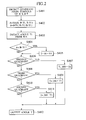
- the angle calculation unit 4 calculates an angle formed by the input pixels on the color difference plane of FIG.3 by steps shown as one example in FIG.2.
- FIG.2 shows a flowchart of angle calculation steps in the angle calculation unit 4, but the angle calculation steps in the angle calculation unit 4 may be realized by either software or hardware.
- step S401 a quadrant on the color difference plane in which each input pixel is positioned is detected from symbols of components of the color difference signals R-Y, B-Y.
- step S402 for the color difference signals R-Y, B-Y components, a component having a large absolute value is used as A, and a component having a small absolute value is used as B in calculation.
- step S403 angle T1 is detected from B/A.
- the angle T1 is calculated as 0 to 45°.
- the angle T1 can be calculated by line approximation or ROM table. It is judged in step S404 whether or not A is
- is established, T 90-T1 is calculated in step S405. Thereby, tan -1 ((R-Y)/(B-Y)) is obtained.
- the angle T1 to be detected in the step S403 is set to 0 to 45°, because an angle exceeding 45° is inappropriate for the calculation of the angle. If the angle exceeds 45°, a curve of tan -1 ((R-Y)/(B-Y)) rapidly has a large gradient.
- step S406 data of the quadrant detected in the step S401 is used to judge whether or not the quadrant is a second quadrant.
- T 180 - T1 is calculated.
- step S408 determines whether or not the quadrant is a third quadrant.
- step S410 determines whether or not the quadrant is a fourth quadrant.
- step S412 the angle T formed by the respective input pixels on the color difference plane of FIG.3 is outputted.
- the angle on the color difference plane of the inputted color difference signals R-Y, B-Y can be obtained in a range of 0 to 360°.
- the steps S404 to S411 correspond to steps of correcting the angle T1 detected in the step S403 to be the angle T.
- the angle T1 is corrected in accordance with the first to fourth quadrants in the steps S404 to S411.
- the correction processing of the angle T1 to the angle T differs depending on whether or not
- the above-described angle calculation processing in the angle calculation unit 4 comprises: calculating the angle formed by the color difference signals R-Y, B-Y as the angle T1 in the range of 0 to 45°; correcting this angle T1 in accordance with each quadrant; and calculating the angle formed by the color difference signals R-Y, B-Y as T in the range of 0 to 360°.
- This constitution is effective particularly for constituting the present invention as hardware (video correction apparatus) such as an integrated circuit and using the line approximation to calculate the angle.
- a low pass filter is preferably used for the color difference signals R-Y, B-Y for use in angle calculation (i.e., the color difference signals R-Y, B-Y inputted into the angle calculation unit 4) in order to reduce the noise.
- angle calculation i.e., the color difference signals R-Y, B-Y inputted into the angle calculation unit 4
- the angle of the color difference signals R-Y, B-Y can correctly be calculated.
- the angle T outputted from the angle calculation unit 4 is inputted into correction gain calculation units 51, 52, ..., 5n.
- n correction gain calculation units are disposed, but one or a plurality of correction gain calculation units may arbitrarily be disposed.
- the correction gain calculation unit is disposed in accordance with the number of regions in which the hue or chroma is corrected. Therefore, when only the specific color as one angle region on the color difference plane is corrected, one correction gain calculation unit may be disposed. All the correction gain calculation units 51 to 5n have the same constitution.
- L0, L1, L2 are isochromatic lines extending from the intersection of the B-Y and R-Y axes, and angles of the isochromatic lines L0, L1, L2 are ⁇ 0, ⁇ 1, ⁇ 2.
- the isochromatic line L0 is a center line of correction, and a range of the angles ⁇ 1 and ⁇ 2 surrounded by the isochromatic lines L1, L2 is a correction region in which the hue, chroma, or luminance is corrected.
- the angles ⁇ 0 to ⁇ 2 can arbitrarily be set under the condition of ⁇ 1 ⁇ ⁇ 0 ⁇ ⁇ 2.
- An angle ( ⁇ 0- ⁇ 1) formed by the isochromatic lines L0, L1 and angle ( ⁇ 2- ⁇ 0) formed by the isochromatic lines L0, L2 may not be the same, but are preferably the same.
- a correction angle R from the angle ⁇ 0 is set, ⁇ 0-R is set to ⁇ 1, and ⁇ 0+R is set to ⁇ 2. It is to be noted that when a plurality of correction regions are disposed on the color difference plane, the isochromatic line similar to the isochromatic lines L0 to L2 may be set in a plurality of angle positions.
- the angles ⁇ 0, ⁇ 1, ⁇ 2, or the angles ⁇ 0 and R for determining the respective correction regions are inputted into the correction gain calculation units 51 to 5n.
- the angles supplied to the correction gain calculation units 51 to 5n are ⁇ 0, ⁇ 1, ⁇ 2, and the angles ⁇ 0, ⁇ 1, ⁇ 2 are angles ⁇ 01, ⁇ 11, ⁇ 21 to ⁇ 0n, ⁇ 1n, ⁇ 2n with respect to the correction gain calculation units 51 to 5n. It is to be noted that it is also possible to superpose and set the correction regions.
- angles ⁇ 01 to ⁇ 0n will generically referred to as the angle ⁇ 0
- angles ⁇ 11 to ⁇ 1n will generically referred to as the angle ⁇ 1
- angles ⁇ 21 to ⁇ 2n will generically referred to as the angle ⁇ 2.
- the correction gain calculation units 51 to 5n generate a first correction function M12 for correcting the video (hue, chroma, luminance) based on the following equation (5).
- M12 Min(F L1 , F L2 );
- the first correction function M12 selects a smaller one from F L1 represented by the equation (3) and F L2 represented by the equation (4), and a triangular characteristic having an apex in the angle ⁇ 0 is obtained as shown in FIG.4C.
- the characteristic of the first correction function M12 is not limited to the triangular shape. Alternatively, an upper limit value may also be set to obtain a trapezoidal or cosine function characteristic. It is to be noted that it is necessary for the first correction function M12 to set the outside of the angles ⁇ 1, ⁇ 2 as a range outside a correction range to zero.
- the correction gain calculation units 51 to 5n generate a second correction function M012 for correcting the video (hue, chroma, or luminance) based on the following equation (7).
- M012 Min(F L0 , F L1 );
- M012 Max(M012, -F L2 );
- the second correction function M012 selects a smaller one from F L0 represented by the equation (6) and F L1 represented by the equation (3). Furthermore, a larger one is selected from M012 and -F L2 obtained thereby.
- the second correction function M012 obtained in this manner has a characteristic constituted by combining an upper convex triangular characteristic which has a positive apex in a middle portion between the angles ⁇ 1 and ⁇ 0 with a lower convex triangular characteristic which has a negative apex in the middle portion between the angles ⁇ 0 and ⁇ 2. It is necessary for the second correction function M012 to set the outside of the angles ⁇ 1, ⁇ 2 as the outside of the appropriate range to zero.
- the angle T calculated by the angle calculation unit 4 indicates a value of 0 to 360°.
- the angle ⁇ 1 or ⁇ 2 strides over 0° or 360° discontinuity is generated in the value of the angle.
- the angle T is corrected to be a continuous value, and the discontinuity of the value of the angle T can be prevented from being caused in the range of the angle ⁇ 1 to ⁇ 2 by the equation (8). Therefore, the first and second correction functions M12, M012 shown in FIGS.4C, 4E can correctly be generated.
- the correction angle R can be set up to nearly 180°, that is, the correction region of ⁇ 0 ⁇ 180° can be set.
- coefficients p1, p2, s1 y1, c1 are inputted into the correction gain calculation units 51 to 5n.
- the coefficients p1 p2 are coefficients for setting a hue correction gain described later to be variable
- the coefficient s1 is a coefficient for setting a chroma correction gain described later to be variable.
- the coefficient y1 is a coefficient for setting a luminance gamma correction gain described later to be variable
- the coefficient c1 is a coefficient for setting a chroma gamma correction gain described later to be variable.
- the chroma is also corrected.
- a characteristic of gamma curve is imparted to the luminance signal.
- the characteristic of gamma curve is imparted to a color difference signal in the same manner as in the luminance correction. Therefore, in the present embodiment, the correction of the luminance signal will be referred to as Y gamma, and the chroma correction performed together with the correction of the luminance signal will be referred to as C gamma.
- the correction gain calculation units 51 to 5n generate correction gains P, S, Gy, Gc based on correction gain calculation equations P(T), S(T), Gy(T), Gc(T) represented by the following equations (9) to (12) using the first and second correction functions M12, M012 generated as described above and inputted coefficients p1, p2, s1, y1, c1.
- P denotes a phase correction gain for use in correcting the gain of hue
- S denotes a chroma correction gain for use in correcting the gain of chroma
- Gy denotes a Y gamma correction gain for use in correcting the gain of Y gamma
- Gc denotes a C gamma correction gain for use in correcting the gain of C gamma.
- the first and second correction functions M12, M012 are functions in which the angle T calculated by the angle calculation unit 4 is used as the parameter, and the correction gain calculation equations represented by the equations (9) to (12) are functions in which the angle T is used as the parameter.
- the first correction function M12 shown in FIG.4C has a characteristic that a correction amount becomes larger closer to the isochromatic line L0 with the center angle ⁇ 0 of the correction region, and also has a characteristic that the pixel in the correction region is corrected in one direction.
- the second correction function M012 shown in FIG.4E has a characteristic that the correction amount becomes zero on the isochromatic line L0 and is maximized in middle portions between the isochromatic line L0 and the isochromatic lines L1, L2. Moreover, the function has a characteristic that the correction direction is inverted in the angle region held between the isochromatic lines L0 and L1 and the angle region held between the isochromatic lines L0 and L2.
- the coefficients p1, p2, s1, y1, c1 are used to set the amplitudes of the first and second correction functions M12, M012 to be variable, and to appropriately set degrees of the correction gains P, S, Gy, Gc generated by the correction gain calculation equations P(T), S(T), Gy(T), Gc(T).
- the correction of the hue by the equation (9) is performed only in the correction region surrounded by the angles ⁇ 1 to ⁇ 2, and influence of the correction is not exerted outside the correction region.
- the present embodiment is constituted such that the first and second correction functions M12, M012 are generated and the hue correction gain P is generated by the correction gain calculation equation P(T) of the equation (9).
- the function is equivalent to that of FIG.5A. Therefore, without generating the second correction function M012, the correction gain calculation equation equivalent to the equation (9) can be obtained only with the first correction function M12. In this constitution, it is unnecessary to generate the second correction function M012.
- the first correction function M12 is used in the correction gain calculation equations S(T), Gy(T), Gc(T) for calculating the correction gains of chroma, Y gamma, and C gamma.
- the correction of the chroma, Y gamma, C gamma by the equations (10) to (12) is performed only in the correction region surrounded with the angles ⁇ 1 to ⁇ 2, and the influence of correction is not exerted outside the correction region.
- FIG.1 shows Pi, Si, Gyi, Gci simply as P, S, Gy, Gc.
- the correction gains Si, Pi, Gyi, Gci outputted from the correction gain calculation units 51 to 5n are accumulated (summed) by accumulators 6 to 9.
- the outputs of the accumulators 6 to 9 are denoted by ⁇ Si, ⁇ Pi, ⁇ Gyi, ⁇ Gci.
- the color difference signals R-Y, B-Y and luminance signal Y are subjected to the correction using the correction gains Si, Pi, Gyi, Gci.
- the correction gains Si, Pi, Gyi, Gci are accumulated/summed, and therefore the circuit constitution of the correction calculation processing in the subsequent stage is simplified with respect to the color difference signals R-Y, B-Y and luminance signal Y.
- the correction gain is a sum.
- the correction gain turns to 0.
- the color difference signal R-Y inputted into the input terminal 1 is inputted into a multiplier 10, adder 13, and inverter 14, and the color difference signal B-Y inputted into the input terminal 2 is inputted into multipliers 11, 15 and adder 18.
- the output of the inverter 14 is inputted into a multiplier 16.
- the correction gain ⁇ Si outputted from the accumulator 6 is inputted into the multipliers 10, 15.
- the multiplier 10 multiplies the color difference signal R-Y by the correction gain ⁇ Si and outputs a result
- the multiplier 15 multiplies the color difference signal B-Y by the correction gain ⁇ Si and outputs a result.
- the correction gain ⁇ Pi outputted from the accumulator 7 is inputted into the multipliers 11, 16.
- the multiplier 11 multiplies the color difference signal B-Y by the correction gain ⁇ Pi and outputs a result
- the multiplier 16 multiplies the color difference signal R-Y reversed by the inverter 14 by the correction gain ⁇ Pi and outputs a result.
- An adder 12 adds the outputs of the multipliers 10, 11, and the adder 13 adds the color difference signal R-Y and the output of the adder 12.
- the output of the adder 13 is the color difference signal R-Y after the correction.
- An adder 17 adds the outputs of the multipliers 15, 16, and the adder 18 adds the color difference signal B-Y and the output of the adder 17.
- the output of the adder 18 is the color difference signal B-Y after the correction.
- the chromaticity point of the inputted pixel is represented by (B-Y), (R-Y).
- a vector crossing at right angles to the vector is -(R-Y), (B-Y). Therefore, it is seen that the first terms - ⁇ Pi ⁇ (R-Y).
- ⁇ Pi ⁇ (B-Y) of the equations (14) and (13) represent hue correction components in a direction crossing at right angles to the vector of the chromaticity point of the pixel as the object of correction.
- the second terms ⁇ Si ⁇ (B-Y), ⁇ Si ⁇ (R-Y) of the equations (14) and (13) represent the correction in the same direction as that of the vector of the chromaticity point of the pixel as the object of correction, that is, chroma correction components.
- each chromaticity point of the pixel in the correction region is moved in a direction crossing at right angles to the isochromatic line connecting the intersection of the R-Y and B-Y axes to the pixel in the correction region.
- the hue substantially rotates/moves in the whole correction region.
- each chromaticity point of the pixel in the correction region is moved in a direction extending in parallel with the isochromatic line connecting the intersection of the R-Y and B-Y axes to the pixel in the correction region (a direction in which the chroma is either enlarged or reduced on the isochromatic line).
- a first circuit block of the multipliers 10, 11 and adders 12, 13 and second circuit block of the multipliers 15, 16, inverter 14, and adders 17, 18 calculate the color difference signals R-Y, B-Y and correction gains ⁇ Pi, ⁇ Si to thereby generate the color difference signals R-Y, B-Y subjected to the hue and chroma correction.
- These first and second circuit blocks operate as correction means for correcting the hue and chroma.
- the color difference signals R-Y, B-Y outputted from the adders 13, 18 and subjected to the hue and chroma correction are inputted into the luminance/color difference gamma processing unit 19.
- the chromaticity point is moved in the direction crossing at right angles to each isochromatic line connecting the intersection of the R-Y and B-Y axes to each pixel in the correction region.
- the correction amount movement amount
- the pixel in the correction region can be regarded as moving substantially in the rotation direction.
- the correction amount is large, the pixel in the correction region cannot be regarded as moving in the rotation direction.
- the chroma also changes.
- Equations for moving the chromaticity point of the pixel in the rotation direction on the color difference plane can be represented by the following equations (15), (16).
- the color difference signal R-Y corrected by the equation (15) is obtained, and the color difference signal B-Y corrected by the equation (16) is obtained.
- the portions of the first circuit block of the multipliers 10, 11 and adders 12, 13 and the second circuit block of the multipliers 15, 16, inverter 14, and adders 17, 18 may also be replaced with a circuit constitution for realizing the equations (15), (16).
- the equations (15), (16) may also be realized by software.
- the luminance signal Y inputted into the input terminal 3, and correction gains ⁇ Gyi, ⁇ Gci outputted from the accumulators 8, 9 are inputted into the luminance/color difference gamma processing unit 19 as described above.
- the luminance/color difference gamma processing unit 19 includes the correction function represented by the following equation (19).
- G(X) X 1/1.5 - X
- the luminance/color difference gamma processing unit 19 subjects the luminance signal Y and color difference signals R-Y, B-Y to gamma correction, and X (the abscissa of FIG.6) in the equation (19) indicates the values of the luminance signal Y and color difference signals R-Y, B-Y.
- X the abscissa of FIG.6
- optimum characteristic depends upon each display device.
- the equation (19) is one example, and the correction characteristic in the luminance/color difference gamma processing unit 19 is not limited to the equation (19).
- the luminance/color difference gamma processing unit 19 multiplies the correction gain ⁇ Gyi by the correction function G(X), and adds this multiplication result to the luminance signal Y. That is, the calculation processing of the following equation (20) is performed. Y + G(X) ⁇ Gyi
- correction gain ⁇ Gyi is a coefficient for setting the amplitude of the correction function G(X) shown in FIG.6 to be variable.
- the luminance/color difference gamma processing unit 19 gamma-corrects the inputted color difference signals R-Y, B-Y.
- the luminance/color difference gamma processing unit 19 multiplies each of the color difference signals R-Y, B-Y by the correction gain ⁇ Gci and correction functions G(X) and 1/X. and adds the multiplication result to the color difference signals R-Y, B-Y. That is, the calculation processing of the following equations (21), (22) is performed. (R-Y) + (R-Y) ⁇ G(X) ⁇ Gci/X (B-Y) + (B-Y) ⁇ G(X) ⁇ Gci/X
- the luminance signal Y subjected to Y gamma outputted from the luminance/color difference gamma processing unit 19 is outputted from an output terminal 22, and the color difference signals R-Y, B-Y subjected to the C gamma are outputted from output terminals 20, 21.
- the signals may be converted to the three primary colors signals by linear matrix computation.
- the hue and chroma of the color difference signals R-Y, B-Y and luminance signal Y inputted into the input terminals 1 to 3 can be corrected only in the predetermined correction region. Furthermore, in addition to the correction, Y gamma and C gamma can be applied. In the present embodiment, the correction of all the hue, chroma, Y gamma, and C gamma has been described. However, only one arbitrary element of these elements may be corrected, or an arbitrary combination may also be corrected. Additionally, it is preferable to apply the Y and C gammas as a set.
- the correction of the hue and chroma by the first circuit block including the multipliers 10, 11 and adders 12, 13 and the second circuit block including the multipliers 15, 16, inverter 14, and adders 17, 18 has no relation to the value of the luminance signal Y.
- the correction amount of the hue or chroma may be allowed to differ in accordance with the value of the luminance signal Y.
- the coefficients p1 p2, s1 inputted into the correction gain calculation units 51 to 5n may be changed in accordance with the value of the luminance signal Y.
- FIG.7 One example of the characteristic in changing the coefficient s1 in accordance with the value of the luminance signal Y and varying the correction amount of chroma is shown in FIG.7.
- the abscissa indicates the luminance signal Y, and the ordinate indicates the coefficient s1.
- the chroma is lowered at a low luminance, and raised at a high luminance.
- a table shown in FIG.8 can be used as means for changing the coefficient s1, as one example.
- FIG.8 the coefficient s1 having various values is stored in a table 31.
- the value of the luminance signal Y is inputted as an address, and the coefficient s1 is outputted from the table 31 in accordance with the value of the inputted luminance signal Y.
- the coefficients p1, p2 are changed in accordance with the value of the luminance signal Y.
- FIG.9 a Y-axis indicating the value of the luminance signal Y crosses at right angles to a color difference plane formed by the R-Y and B-Y axes.
- each of Y0, Y1, Y2 denotes equal luminance plane.
- I conceptually shows the correction of the hue and chroma of the pixel shown by a white circle into a position shown by a black circle irrelevantly to the value of the luminance signal Y.
- FIG.9 II conceptually shows the correction of the hue and chroma of the pixel shown by the white circle into the position shown by the black circle in accordance with the value of the luminance signal Y.
- III shown in FIG.9 conceptually shows the application of Y and C gammas in addition to the correction of I.
- IV conceptually shows the application of the Y and C gammas in addition to the correction of II.
- the constitution of the present invention is shown as hardware, but may of course be realized by software (computer program).
- the constitution of the present invention may be an integrated circuit, program including steps of the present invention, or recording medium on which the program is recorded.
- the recording medium may be an arbitrary medium including an optical disk such as CD-ROM, or another disk.
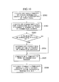
- FIG.10 is a flowchart showing a processing procedure in a case in which a constitution of the present invention is realized in software (computer program).
- the video correction method or program of the present invention includes the following steps. First, as step S501, an angle calculation step of calculating the angle formed by the components of the color difference signals R-Y, B-Y on the color difference plane of each input pixel is included.
- the method or program includes a correction gain calculation step of: using the angle of each input pixel calculated by the angle calculation step as a parameter to set the correction gain for correcting the hue, chroma, Y gamma, C gamma of the pixel of the video signal outside the correction region to zero, and to calculate the correction gain for correcting the hue, chroma, Y gamma, C gamma of the pixel in the correction region based on the correction gain calculation equation for generating a predetermined correction gain in the correction region.
- the method or program includes an accumulation step of accumulating the respective correction gains of the plurality of correction regions as step S504. When there is only one correction region, this accumulation step is not necessary.
- step S505 a correction step of calculating the color difference signals R-Y, B-Y and the correction gains of hue and chroma, and correcting the hue and chroma of the pixel in the correction region is included.
- the method or program includes a step of: adding the value obtained by multiplying the correction gain of Y gamma by a predetermined correction function to the luminance signal Y to correct (Y gamma correction) the luminance signal Y; adding the value obtained by multiplying each of the color difference signals R-Y, B-Y by the correction gain and correction function of C gamma to each of the color difference signals R-Y, B-Y to correct (C gamma correction) the color difference signals R-Y, B-Y.
- steps S501 to S504 need to be performed in this order.
- the steps S505 and S506 may also be performed at the same timing, and either step may temporally come before.
- the present invention can be used not only for a purpose of correction of dispersions of the chromaticity point or dispersions of video caused by an image pickup apparatus but also for a purpose of intentional correction of a specific color.
- a specific color For example, green color of grasses or trees can be changed to yellow or brown to thereby change sense of the season of video. Since the hue, chroma, or luminance (gradation) of the specific color of video can arbitrary be varied, the present invention can be used in various purposes.
- the present invention is not limited to the above-described embodiment, and can variously be changed in a range without departing from the scope of the present invention.
- the color difference signals have been described as R-Y, B-Y, but are not limited to R-Y, B-Y.
- the video correction apparatus and method, video correction program, and recording medium on which the program is recorded comprising: angle calculation means (step) for calculating the angle formed by the first and second color difference signal components on the color difference plane of each input pixel; correction gain calculation means (step) for using the angle of each input pixel calculated by the angle calculation means (step) as the parameter to set the correction gain for correcting the hue or chroma of the pixel of the video signal to zero outside the correction region, and to calculate the correction gain for correcting the hue or chroma of the pixel in the correction region based on the correction gain calculation equation for generating the predetermined correction gain in the correction region; and hue correction means (step) for calculating the first and second color difference signals and correction gain to thereby correct the hue or chroma of the pixel in the correction region. Therefore, even when the correction region is a broad angle region, the hue or chroma can exactly be corrected.
- the luminance correction gain only in the correction region is calculated, multiplied by the correction function, and added to the luminance signal components, so that the luminance signal can be corrected together with the correction of the hue and chroma. Since the color difference correction gain and correction function only in the correction region are used to correct the color difference signal together with the correction of the luminance signal, the apparently changing chroma can be corrected together with the correction of the luminance signal, and the correction is possible without collapsing a balance of luminance and chroma of video.
Landscapes
- Engineering & Computer Science (AREA)
- Multimedia (AREA)
- Signal Processing (AREA)
- Processing Of Color Television Signals (AREA)
- Image Processing (AREA)
Abstract
Description
- The present invention relates to a video correction apparatus and method in which hue, chroma, and luminance of a video signal are corrected, a video correction program, and a recording medium on which the program is recorded.
- There are various types of display for displaying a video signal, and chromaticity points of three primary colors disperse for various display types. Further chromaticity points disperse for displays of the same type. Furthermore even in the video signal generated by an image pickup apparatus, deviations of tone (hue or chroma) and/or gradation (luminance) occur because of dispersion of three primary colors in an image pickup apparatus or difference in image pickup condition. Then, it is sometimes necessary to correct the hue, chroma, and luminance.
- Meanwhile, as a base band video signal, either three primary colors signals of red (R), green (G), blue (B), or luminance signal (Y), and two color difference signals (R-Y, B-Y, or Pb, Pr) are used. The signals displayed in the display are three primary colors signals of R, G, B. However, when it is necessary to correct the hue or chroma, the color difference signals are processed more easily than the three primary colors signals, and therefore the color difference signals are generally used as the signals to be subjected to the correction processing of the hue or chroma. It is to be noted that the three primary colors signals, and luminance and color difference signals can easily be converted to each other by linear matrix computation.
- Examples of a related-art correction processing of the hue and chroma include one example of a computation processing represented by the following equations (1), (2). In the equations (1), (2), R-Y, B-Y denote the color difference signals before the correction, r-y, b-y denote the color difference signals after the correction, and A1, A2 are coefficients. As well known, two color difference signals are represented by a plane (color difference plane) including two axes crossing at right angles to each other. T1, T2 in the equations (1), (2) denote correction angles on the color difference plane.
- When the coefficients A1, A2 are different in the equations (1), (2), amplitudes (chroma) of the color difference signals r-y, b-y can individually be set. When the angles T1, T2 are different, rotation angles of the color difference signals R-Y, B-Y are different, and therefore the hue can non-uniformly be corrected. When the coefficients A1, A2 and angles T1, T2 are the same, the chroma and hue can uniformly be corrected. In any case, all regions on the color difference plane whose axes are two color difference signals change in the correction processing by the equations (1), (2).
- As other related-art examples, and color correction circuits for correcting the hue and chroma in a specific range, there are Japanese Patent Application Laid-Open Nos. 10(1998)-145805 and 2001-128189.
- Since the whole hue is corrected in the related-art correction processing by the equations (1), (2), there is a serious disadvantage that the hue or chroma cannot be corrected only in a specific angle region on the color difference plane as a specific hue region. The color correction circuit described in the Japanese Patent Application Laid-Open No.2001-128189 is an example of the correction processing in which this disadvantage is avoided. According to this color correction circuit, only the specific angle region is set as the correction region, and the hue or chroma of pixels in the correction region can be corrected.
- However, the color correction circuit of the above-described publication has a problem that the hue of all the pixels in an angle region surrounded with two isochromatic lines is corrected in a direction crossing at right angles to an isochromatic line which is a center line of the two isochromatic lines, and the chroma of all the pixels is corrected in a direction parallel to the center isochromatic line. When the angle region as the correction region is enlarged, the hue or chroma is exactly corrected in the vicinity of the center isochromatic line, but the hue or chroma cannot exactly be corrected in a region distance from the center isochromatic line. Therefore, there is a problem that a broad angle region cannot be the correction region.
- Moreover, there is a problem that the hue or chroma can be corrected, but the luminance signal (gradation) cannot be corrected in accordance with the correction of the hue or chroma. Furthermore, when the luminance signal is corrected, the chroma apparently changes. Therefore, the chroma has to be also corrected in accordance with the correction of the luminance signal, but there is a problem that the chroma changing with the correction of the luminance signal cannot be corrected.
- In the related art, a practical video correction apparatus and method or a video correction program has not heretofore been found in which the hue, chroma, and luminance can be corrected to be optimum in consideration of balance of video and/or each element of the hue, chroma, and luminance can freely be corrected. There has increasingly been a demand for a higher image quality with respect to an image to be displayed in the display, and there has been a sincere demand for a video correction apparatus and method or video correction program in which the video can arbitrarily be corrected to be optimum. At this time, the video correction apparatus and method or video correction program can preferably be realized easily and inexpensively without complicating a constitution or step.
- The present invention has been developed in consideration of these problems, and an object of the present invention is to provide a video correction apparatus and method in which hue or chroma can exactly be corrected even with a broad angle region as a correction region, a video correction program for the exact correction, and a recording medium on which the program for the exact correction is recorded. Another object of the present invention is to provide a video correction apparatus and method in which hue or chroma can be corrected only in one or a plurality of specific correction regions and a luminance signal can be corrected in accordance with the correction of the hue or chroma, a video correction program for the correction, and a recording medium on which the program for the correction is recorded.
- Further object of the present invention is to provide a video correction apparatus and method in which the chroma changing with the correction of the luminance signal can be corrected, a video correction program for the correction, and a recording medium on which the program for the correction is recorded. Still further object of the present invention is to easily and inexpensively realize a video correction apparatus and method in which video can arbitrarily be corrected to be optimum, a video correction program for the optimum correction, and a recording medium on which the program for the optimum correction is recorded.
- To achieve the objects, there is provided a video correction apparatus for setting one or a plurality of angle regions on a color difference plane formed by first and second axes as correction regions, and correcting video in the correction regions, when one of first and second color difference signals which are color signal components of a pixel of a video signal is used as the first axis, and the other of the first and second color difference signals is used as the second axis crossing at right angles to the first axis, the apparatus comprising: angle calculation means for calculating an angle formed by components of the first and second color difference signals of each input pixel on the color difference plane; hue correction gain calculation means for using the angle of each input pixel calculated by the angle calculation means as a parameter to set a hue correction gain for correcting hue of the pixel of the video signal to zero outside the correction regions and to calculate the hue correction gain for correcting the hue of the pixel in each correction region based on a hue correction gain calculation equation for generating a predetermined hue correction gain for each correction region; and hue correction means for correcting the hue of the pixel in each correction region by a calculation using the first and second color difference signals and the hue correction gain.
- Moreover, to achieve the object, there is provided a video correction apparatus for setting a plurality of angle regions on a color difference plane formed by first and second axes as a plurality of correction regions, and correcting video in the correction regions, when one of first and second color difference signals which are color signal components of a pixel of a video signal is used as the first axis, and the other of the first and second color difference signals is used as the second axis crossing at right angles to the first axis, the apparatus comprising: angle calculation means for calculating an angle formed by components of the first and second color difference signals of each input pixel on the color difference plane; a plurality of hue correction gain calculation means for using the angle of each input pixel calculated by the angle calculation means as a parameter to set a hue correction gain for correcting hue of the pixel of the video signal to zero outside the correction regions and to calculate the hue correction gain for correcting the hue of the pixel in each correction region with respect to the plurality of correction regions based on a hue correction gain calculation equation for generating a predetermined hue correction gain for each correction region; first accumulation means for accumulating the hue correction gains for the plurality of correction regions calculated by the plurality of hue correction gain calculation means; and hue correction means for correcting the hue of the pixel in each correction region by a calculation using the first and second color difference signals and the hue correction gains accumulated by the first accumulation means.
- Furthermore, to achieve the objects, there is provided a video correction method for setting one or a plurality of angle regions on a color difference plane formed by first and second axes as correction regions, and correcting video in the correction regions, when one of first and second color difference signals which are color signal components of a pixel of a video signal is used as the first axis, and the other of the first and second color difference signals is used as the second axis crossing at right angles to the first axis, the method comprising: an angle calculation step of calculating an angle formed by components of the first and second color difference signals of each input pixel on the color difference plane; a hue correction gain calculation step of using the angle of each input pixel calculated in the angle calculation step as a parameter to set a hue correction gain for correcting hue of the pixel of the video signal to zero outside the correction regions and to calculate the hue correction gain for correcting the hue of the pixel in each correction region based on a hue correction gain calculation equation for generating a predetermined hue correction gain for each correction region; and a hue correction step of correcting the hue of the pixel in each correction region by a calculation using the first and second color difference signals and hue correction gain.
- Additionally, to achieve the objects, there is provided a video correction method for setting a plurality of angle regions on a color difference plane formed by first and second axes as a plurality of correction regions, and correcting video in the correction regions, when one of first and second color difference signals which are color signal components of a pixel of a video signal is used as the first axis, and the other of the first and second color difference signals is used as the second axis crossing at right angles to the first axis, the method comprising: an angle calculation step of calculating an angle formed by components of the first and second color difference signals of each input pixel on the color difference plane; a plurality of hue correction gain calculation steps of using the angle of each input pixel calculated in the angle calculation step as a parameter to set a hue correction gain for correcting hue of the pixel of the video signal to zero outside the correction regions and to calculate the hue correction gain for correcting the hue of the pixel in each correction region with respect to the plurality of correction regions based on a hue correction gain calculation equation for generating a predetermined hue correction gain for each correction region; a first accumulation step of accumulating the hue correction gains for the plurality of correction regions calculated by the plurality of hue correction gain calculation steps; and a hue correction step of correcting the hue of the pixel in each correction region by a calculation using the first and second color difference signals and the hue correction gains accumulated by the first accumulation step.
- Moreover, to achieve the object, there is provided a video correction program for setting one or a plurality of angle regions on a color difference plane formed by first and second axes as correction regions, and correcting video in the correction regions, when one of first and second color difference signals which are color signal components of a pixel of a video signal is used as the first axis, and the other of the first and second color difference signals is used as the second axis crossing at right angles to the first axis, the program comprising: an angle calculation step of calculating an angle formed by components of the first and second color difference signals of each input pixel on the color difference plane; a hue correction gain calculation step of using the angle of each input pixel calculated in the angle calculation step as a parameter to set a hue correction gain for correcting hue of the pixel of the video signal to zero outside the correction regions and to calculate the hue correction gain for correcting the hue of the pixel in each correction region based on a hue correction gain calculation equation for generating a predetermined hue correction gain for each correction region; and a hue correction step of correcting the hue of the pixel in each correction region by a calculation using the first and second color difference signals and hue correction gain.
- Furthermore, to achieve the objects, there is provided a video correction program for setting a plurality of angle regions on a color difference plane formed by first and second axes as a plurality of correction regions, and correcting video in the correction regions, when one of first and second color difference signals which are color signal components of a pixel of a video signal is used as the first axis, and the other of the first and second color difference signals is used as the second axis crossing at right angles to the first axis, the program comprising: an angle calculation step of calculating an angle formed by components of the first and second color difference signals of each input pixel on the color difference plane; a plurality of hue correction gain calculation steps of using the angle of each input pixel calculated in the angle calculation step as a parameter to set a hue correction gain for correcting hue of the pixel of the video signal to zero outside the correction regions and to calculate the hue correction gain for correcting the hue of the pixel in each correction region with respect to the plurality of correction regions based on a hue correction gain calculation equation for generating a predetermined hue correction gain for each correction region; a first accumulation step of accumulating the hue correction gains for the plurality of correction regions calculated in the plurality of hue correction gain calculation steps; and a hue correction step of correcting the hue of the pixel in each correction region by a calculation using the first and second color difference signals and the hue correction gains accumulated in the first accumulation step.
- The nature, principle and utility of the invention will become more apparent from the following detailed description when read in conjunction with the accompanying drawings.
- In the accompanying drawings:
- FIG.1 is a block diagram showing one embodiment of the present invention;
- FIG.2 is a flowchart showing concrete processing in an angle calculation unit 4 in FIG.1;
- FIG.3 is a diagram showing a color difference plane;
- FIGS.4A to 4E are explanatory views of correction functions for use in correction gain calculation units 51 to 5n in FIG.1;
- FIGS.5A and 5B are explanatory views of the correction functions shown in FIGS.4A to 4E;
- FIG.6 is an explanatory view of the correction function for use in a luminance/color difference gamma processing unit 19 in FIG.1;
- FIG.7 is a diagram showing a conversion characteristic example in which a coefficient of a chroma correction gain is variable in accordance with a luminance signal;
- FIG.8 is a block diagram showing one example of means for setting the coefficient of the chroma correction gain in accordance with the luminance signal;
- FIG.9 is a diagram schematically showing a function in a case in which the coefficient of the hue/chroma correction gain is set to be variable in accordance with the luminance signal; and
- FIG.10 is a flowchart showing a processing procedure in a case in which a constitution of the present invention is realized in software (computer program).
-
- A video correction apparatus and method, video correction program, and recording medium on which the program is recorded will be described hereinafter with reference to the accompanying drawings.
- In FIG.1, color difference signals R-Y, B-Y are inputted into input terminals 1, 2, and are then inputted into an angle calculation unit 4. A luminance signal Y is inputted into an input terminal 3, and is then inputted into a luminance/color difference gamma processing unit 19. The color difference signals R-Y, B-Y and luminance signal Y are successively inputted for each pixel of the video signal as an object of correction. It is to be noted that when the video signals as the objects of correction are three primary colors signals, the three primary colors signals are converted to the color difference signals R-Y, B-Y and luminance signal Y beforehand by linear matrix calculation, and the signals are inputted into the angle calculation unit 4 and luminance/color difference gamma processing unit 19.
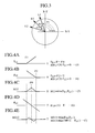
- As shown in FIG.3, one color difference signal (e.g., B-Y) of the color difference signals R-Y, B-Y is indicated on the abscissa, the other color difference signal (e.g., R-Y) is indicated on the ordinate crossing at right angles to the abscissa, and the color difference signals R-Y, B-Y are represented on a color difference plane. A rotation direction centering on an intersection of R-Y and B-Y axes of the color difference plane represents a hue, and a radial direction represents a chroma. Color signal components of each pixel of a video signal are represented by the color difference signals R-Y, B-Y, and each pixel is positioned on the color difference plane. Moreover, colors such as red, blue, green are positioned on the color difference plane, and each color can be represented by an angle from the B-Y axis.
- The angle calculation unit 4 calculates an angle formed by the input pixels on the color difference plane of FIG.3 by steps shown as one example in FIG.2. FIG.2 shows a flowchart of angle calculation steps in the angle calculation unit 4, but the angle calculation steps in the angle calculation unit 4 may be realized by either software or hardware. In FIG.2, in step S401, a quadrant on the color difference plane in which each input pixel is positioned is detected from symbols of components of the color difference signals R-Y, B-Y. In step S402, for the color difference signals R-Y, B-Y components, a component having a large absolute value is used as A, and a component having a small absolute value is used as B in calculation.
- Subsequently, in step S403, angle T1 is detected from B/A. As apparent from the processing of the step S402, the angle T1 is calculated as 0 to 45°. The angle T1 can be calculated by line approximation or ROM table. It is judged in step S404 whether or not A is |R-Y|, i.e., |R-Y| > |B-Y|. If |R-Y| > |B-Y| is not established, the angle T1 is set as such to angle T. If |R-Y| > |B-Y| is established, T = 90-T1 is calculated in step S405. Thereby, tan-1((R-Y)/(B-Y)) is obtained.
- The angle T1 to be detected in the step S403 is set to 0 to 45°, because an angle exceeding 45° is inappropriate for the calculation of the angle. If the angle exceeds 45°, a curve of tan-1((R-Y)/(B-Y)) rapidly has a large gradient.
- Furthermore, in step S406, data of the quadrant detected in the step S401 is used to judge whether or not the quadrant is a second quadrant. With the second quadrant, in step S407, T = 180 - T1 is calculated. When the quadrant is not the second quadrant, it is judged in step S408 whether or not the quadrant is a third quadrant. With the third quadrant, in step S409, T = 180 + T1 is calculated. When the quadrant is not the third quadrant, it is judged in step S410 whether or not the quadrant is a fourth quadrant. With the fourth quadrant, in step S411, T = 360 - T1 is calculated. Subsequently, finally in step S412, the angle T formed by the respective input pixels on the color difference plane of FIG.3 is outputted.
- By the above-described processing, the angle on the color difference plane of the inputted color difference signals R-Y, B-Y can be obtained in a range of 0 to 360°. The steps S404 to S411 correspond to steps of correcting the angle T1 detected in the step S403 to be the angle T. Moreover, it is seen that the angle T1 is corrected in accordance with the first to fourth quadrants in the steps S404 to S411. At this time, in the first quadrant, the correction processing of the angle T1 to the angle T differs depending on whether or not |R-Y| > |B-Y| is established.
- The above-described angle calculation processing in the angle calculation unit 4 comprises: calculating the angle formed by the color difference signals R-Y, B-Y as the angle T1 in the range of 0 to 45°; correcting this angle T1 in accordance with each quadrant; and calculating the angle formed by the color difference signals R-Y, B-Y as T in the range of 0 to 360°. This constitution is effective particularly for constituting the present invention as hardware (video correction apparatus) such as an integrated circuit and using the line approximation to calculate the angle.
- When the inputted video signal includes much noise, a low pass filter is preferably used for the color difference signals R-Y, B-Y for use in angle calculation (i.e., the color difference signals R-Y, B-Y inputted into the angle calculation unit 4) in order to reduce the noise. In this case, the angle of the color difference signals R-Y, B-Y can correctly be calculated.
- Returning to FIG.1, the angle T outputted from the angle calculation unit 4 is inputted into correction gain calculation units 51, 52, ..., 5n. Here, n correction gain calculation units are disposed, but one or a plurality of correction gain calculation units may arbitrarily be disposed. The correction gain calculation unit is disposed in accordance with the number of regions in which the hue or chroma is corrected. Therefore, when only the specific color as one angle region on the color difference plane is corrected, one correction gain calculation unit may be disposed. All the correction gain calculation units 51 to 5n have the same constitution.
- Here, functions of the correction gain calculation units 51 to 5n will be described. In FIG.3, L0, L1, L2 are isochromatic lines extending from the intersection of the B-Y and R-Y axes, and angles of the isochromatic lines L0, L1, L2 are 0, 1, 2. The isochromatic line L0 is a center line of correction, and a range of the angles 1 and 2 surrounded by the isochromatic lines L1, L2 is a correction region in which the hue, chroma, or luminance is corrected. The angles 0 to 2 can arbitrarily be set under the condition of 1 < 0 < 2.
- An angle (0-1) formed by the isochromatic lines L0, L1 and angle (2-0) formed by the isochromatic lines L0, L2 may not be the same, but are preferably the same. To set the angle formed by the isochromatic lines L0, L1 to be the same as that formed by the isochromatic lines L0, L2, a correction angle R from the angle 0 is set, 0-R is set to 1, and 0+R is set to 2. It is to be noted that when a plurality of correction regions are disposed on the color difference plane, the isochromatic line similar to the isochromatic lines L0 to L2 may be set in a plurality of angle positions.
- The angles 0, 1, 2, or the angles 0 and R for determining the respective correction regions are inputted into the correction gain calculation units 51 to 5n. In FIG.1, it is assumed that the angles supplied to the correction gain calculation units 51 to 5n are 0, 1, 2, and the angles 0, 1, 2 are angles 01, 11, 21 to 0n, 1n, 2n with respect to the correction gain calculation units 51 to 5n. It is to be noted that it is also possible to superpose and set the correction regions. The angles 01 to 0n will generically referred to as the angle 0, the angles 11 to 1n will generically referred to as the angle 1, and the angles 21 to 2n will generically referred to as the angle 2.
- The functions of the correction gain calculation units 51 to 5n will further be described with reference to FIGS.4A to 4E. Assuming that a function indicating a portion having an angle larger than that of the isochromatic line L1 of FIG.3 is FL1, this function is represented in C language as follows:
- Similarly, assuming that a function indicating a portion having an angle smaller than that of the isochromatic line L2 of FIG.3 is FL2, this function is represented in the C language as follows:
- The correction gain calculation units 51 to 5n generate a first correction function M12 for correcting the video (hue, chroma, luminance) based on the following equation (5).
- The first correction function M12 selects a smaller one from FL1 represented by the equation (3) and FL2 represented by the equation (4), and a triangular characteristic having an apex in the angle 0 is obtained as shown in FIG.4C. The characteristic of the first correction function M12 is not limited to the triangular shape. Alternatively, an upper limit value may also be set to obtain a trapezoidal or cosine function characteristic. It is to be noted that it is necessary for the first correction function M12 to set the outside of the angles 1, 2 as a range outside a correction range to zero.
- Moreover, similarly, when a function indicating portions having angles larger and smaller than the angle of the isochromatic line L0 of FIG.3 is set to FL0, and represented in the C language, the following is obtained.
- The correction gain calculation units 51 to 5n generate a second correction function M012 for correcting the video (hue, chroma, or luminance) based on the following equation (7).
- The second correction function M012 selects a smaller one from FL0 represented by the equation (6) and FL1 represented by the equation (3). Furthermore, a larger one is selected from M012 and -FL2 obtained thereby. As shown in FIG.4E, the second correction function M012 obtained in this manner has a characteristic constituted by combining an upper convex triangular characteristic which has a positive apex in a middle portion between the angles 1 and 0 with a lower convex triangular characteristic which has a negative apex in the middle portion between the angles 0 and 2. It is necessary for the second correction function M012 to set the outside of the angles 1, 2 as the outside of the appropriate range to zero.
- Additionally, when 1 = 60 - R, 2 = 0 + R are set, the angle T calculated by the angle calculation unit 4 indicates a value of 0 to 360°. When the angle 1 or 2 strides over 0° or 360°, discontinuity is generated in the value of the angle. Then, the correction gain calculation units 51 to 5n correct the angle T for use in the above (3), (4), (6) beforehand by the following equation (8) represented in the C language. It is to be noted that >= in the equation (8) means ≥.
- Even when the angle 1 or 2 strides over 0° or 360°, but when the angle T is included in a range of the angle 1 to 2, the angle T is corrected to be a continuous value, and the discontinuity of the value of the angle T can be prevented from being caused in the range of the angle 1 to 2 by the equation (8). Therefore, the first and second correction functions M12, M012 shown in FIGS.4C, 4E can correctly be generated.
- When 1 = 60 - R, 2 = 0 + R are set as the correction region centering on the angle 0 as described above in the present embodiment, the correction angle R can be set up to nearly 180°, that is, the correction region of 0 ± 180° can be set.
- In addition to the angles 0, 1, 2, coefficients p1, p2, s1 y1, c1 are inputted into the correction gain calculation units 51 to 5n. The coefficients p1 p2 are coefficients for setting a hue correction gain described later to be variable, and the coefficient s1 is a coefficient for setting a chroma correction gain described later to be variable. The coefficient y1 is a coefficient for setting a luminance gamma correction gain described later to be variable, and the coefficient c1 is a coefficient for setting a chroma gamma correction gain described later to be variable. All the coefficients p1, p2, s1, y1, c1 to be inputted into the correction gain calculation units 51 to 5n do not have to be the same with respect to the correction gain calculation units 51 to 5n. When the coefficients p1, p2, s1, y1, c1 are individually set with respect to the correction gain calculation units 51 to 5n, a degree of correction of video can be allowed to differ in a plurality of correction regions.
- In the present embodiment, not only the hue and chroma but also the luminance signal are corrected. Furthermore, when the luminance signal is corrected, the chroma apparently changes. Therefore, with the correction of the luminance signal, the chroma is also corrected. As described later, in the present embodiment, in the correction of the luminance signal, a characteristic of gamma curve is imparted to the luminance signal. Moreover, also in the chroma correction performed together with the correction of the luminance signal, the characteristic of gamma curve is imparted to a color difference signal in the same manner as in the luminance correction. Therefore, in the present embodiment, the correction of the luminance signal will be referred to as Y gamma, and the chroma correction performed together with the correction of the luminance signal will be referred to as C gamma.
- The correction gain calculation units 51 to 5n generate correction gains P, S, Gy, Gc based on correction gain calculation equations P(T), S(T), Gy(T), Gc(T) represented by the following equations (9) to (12) using the first and second correction functions M12, M012 generated as described above and inputted coefficients p1, p2, s1, y1, c1. P denotes a phase correction gain for use in correcting the gain of hue, S denotes a chroma correction gain for use in correcting the gain of chroma, Gy denotes a Y gamma correction gain for use in correcting the gain of Y gamma, and Gc denotes a C gamma correction gain for use in correcting the gain of C gamma.
- As described with reference to FIG.4, the first and second correction functions M12, M012 are functions in which the angle T calculated by the angle calculation unit 4 is used as the parameter, and the correction gain calculation equations represented by the equations (9) to (12) are functions in which the angle T is used as the parameter. The first correction function M12 shown in FIG.4C has a characteristic that a correction amount becomes larger closer to the isochromatic line L0 with the center angle 0 of the correction region, and also has a characteristic that the pixel in the correction region is corrected in one direction.
- On the other hand, the second correction function M012 shown in FIG.4E has a characteristic that the correction amount becomes zero on the isochromatic line L0 and is maximized in middle portions between the isochromatic line L0 and the isochromatic lines L1, L2. Moreover, the function has a characteristic that the correction direction is inverted in the angle region held between the isochromatic lines L0 and L1 and the angle region held between the isochromatic lines L0 and L2. It is seen that the coefficients p1, p2, s1, y1, c1 are used to set the amplitudes of the first and second correction functions M12, M012 to be variable, and to appropriately set degrees of the correction gains P, S, Gy, Gc generated by the correction gain calculation equations P(T), S(T), Gy(T), Gc(T).
- Furthermore, the calculation of the correction gain by the hue correction gain calculation equation P(T) of the equation (9) will be described. For p1×M012 as a first term of the equation (9), as shown in FIG.5A, the hue in the correction region shifts toward the isochromatic line L0 (or in the reverse direction). This is apparent from the characteristic of the second correction function M012. At this time, chromaticity points of the pixels in the angle regions held between the isochromatic lines L0 and L1 and between the isochromatic lines L0 and L2 are substantially rotated/moved in opposite directions with respect to each other.
- Moreover, for a second term p2×M12 of the equation (9), as shown in FIG.5B, the hue in the correction region shifts in one direction. As apparent from the characteristic of the first correction function M12, a shift amount becomes larger closer to the isochromatic line L0. At this time, the chromaticity points of the pixels in the angle regions held between the isochromatic lines L0 and L1 and between the isochromatic lines L0 and L2 are substantially rotated/moved in the same direction with respect to each other.
- The correction of the hue by the equation (9) is performed only in the correction region surrounded by the angles 1 to 2, and influence of the correction is not exerted outside the correction region.
- The present embodiment is constituted such that the first and second correction functions M12, M012 are generated and the hue correction gain P is generated by the correction gain calculation equation P(T) of the equation (9). When two functions of FIG.5B are disposed adjacent to each other on the color difference plane and the phases are allowed to shift in the opposite directions with respect to each other, the function is equivalent to that of FIG.5A. Therefore, without generating the second correction function M012, the correction gain calculation equation equivalent to the equation (9) can be obtained only with the first correction function M12. In this constitution, it is unnecessary to generate the second correction function M012.
- As shown in the above equations (10) to (12), in the correction gain calculation equations S(T), Gy(T), Gc(T) for calculating the correction gains of chroma, Y gamma, and C gamma, the first correction function M12 is used. The correction of the chroma, Y gamma, C gamma by the equations (10) to (12) is performed only in the correction region surrounded with the angles 1 to 2, and the influence of correction is not exerted outside the correction region.
- In FIG.1, outputs of the correction gain calculation units 51 to 5n, namely, correction gains of hue, chroma, Y gamma, C gamma generated by the correction gain calculation equations P(T) to Gc(T) represented by the above equations (9) to (12) are denoted by Pi, Si, Gyi, Gci (i = 1 to n). It is to be noted that FIG.1 shows Pi, Si, Gyi, Gci simply as P, S, Gy, Gc. The correction gains Si, Pi, Gyi, Gci outputted from the correction gain calculation units 51 to 5n are accumulated (summed) by accumulators 6 to 9. The outputs of the accumulators 6 to 9 are denoted by ΣSi, ΣPi, ΣGyi, ΣGci.
- When the chromaticity point of the inputted pixel is included in any correction region, by subsequent-stage calculation processing, the color difference signals R-Y, B-Y and luminance signal Y are subjected to the correction using the correction gains Si, Pi, Gyi, Gci. In the present embodiment, even when there are a plurality of correction gain calculation units, that is, even when a plurality of correction regions are set on the color difference plane, the correction gains Si, Pi, Gyi, Gci are accumulated/summed, and therefore the circuit constitution of the correction calculation processing in the subsequent stage is simplified with respect to the color difference signals R-Y, B-Y and luminance signal Y. When the chromaticity point of the inputted pixel is included in a plurality of correction regions, the correction gain is a sum. When the chromaticity point of the inputted pixel is not included in any correction region, the correction gain turns to 0.
- The color difference signal R-Y inputted into the input terminal 1 is inputted into a multiplier 10, adder 13, and inverter 14, and the color difference signal B-Y inputted into the input terminal 2 is inputted into multipliers 11, 15 and adder 18. The output of the inverter 14 is inputted into a multiplier 16. The correction gain ΣSi outputted from the accumulator 6 is inputted into the multipliers 10, 15. The multiplier 10 multiplies the color difference signal R-Y by the correction gain ΣSi and outputs a result, and the multiplier 15 multiplies the color difference signal B-Y by the correction gain ΣSi and outputs a result. The correction gain ΣPi outputted from the accumulator 7 is inputted into the multipliers 11, 16. The multiplier 11 multiplies the color difference signal B-Y by the correction gain ΣPi and outputs a result, and the multiplier 16 multiplies the color difference signal R-Y reversed by the inverter 14 by the correction gain ΣPi and outputs a result.
- An adder 12 adds the outputs of the multipliers 10, 11, and the adder 13 adds the color difference signal R-Y and the output of the adder 12. The output of the adder 13 is the color difference signal R-Y after the correction. An adder 17 adds the outputs of the multipliers 15, 16, and the adder 18 adds the color difference signal B-Y and the output of the adder 17. The output of the adder 18 is the color difference signal B-Y after the correction.
- It is seen that the above-described multipliers 10, 11 and adders 12, 13 calculate/process the following equation (13), and the multipliers 15, 16, inverter 14, and adders 17, 18 calculate/process the following equation (14). The color difference signal R-Y corrected by the equation (13) is obtained, and the color difference signal B-Y corrected by the equation (14) is obtained.
- As described with reference to FIG.3, the chromaticity point of the inputted pixel is represented by (B-Y), (R-Y). When the chromaticity point is considered as a vector from an origin of the color difference plane of FIG.3, a vector crossing at right angles to the vector is -(R-Y), (B-Y). Therefore, it is seen that the first terms -ΣPi×(R-Y). ΣPi×(B-Y) of the equations (14) and (13) represent hue correction components in a direction crossing at right angles to the vector of the chromaticity point of the pixel as the object of correction. Moreover, it is seen that the second terms ΣSi×(B-Y), ΣSi×(R-Y) of the equations (14) and (13) represent the correction in the same direction as that of the vector of the chromaticity point of the pixel as the object of correction, that is, chroma correction components.
- Therefore, according to the present invention, in the hue correction, each chromaticity point of the pixel in the correction region is moved in a direction crossing at right angles to the isochromatic line connecting the intersection of the R-Y and B-Y axes to the pixel in the correction region. Thereby, the hue substantially rotates/moves in the whole correction region. Moreover, in the chroma correction, each chromaticity point of the pixel in the correction region is moved in a direction extending in parallel with the isochromatic line connecting the intersection of the R-Y and B-Y axes to the pixel in the correction region (a direction in which the chroma is either enlarged or reduced on the isochromatic line).
- Therefore, in the present invention, even when the angle region is set to be large as the correction region, it is possible to exactly correct the hue or chroma as intended.
- As described above, a first circuit block of the multipliers 10, 11 and adders 12, 13 and second circuit block of the multipliers 15, 16, inverter 14, and adders 17, 18 calculate the color difference signals R-Y, B-Y and correction gains ΣPi, ΣSi to thereby generate the color difference signals R-Y, B-Y subjected to the hue and chroma correction. These first and second circuit blocks operate as correction means for correcting the hue and chroma. The color difference signals R-Y, B-Y outputted from the adders 13, 18 and subjected to the hue and chroma correction are inputted into the luminance/color difference gamma processing unit 19.
- Additionally, in the correction of the color difference signals R-Y, B-Y by the above-described equations (13), (14), as described above, the chromaticity point is moved in the direction crossing at right angles to each isochromatic line connecting the intersection of the R-Y and B-Y axes to each pixel in the correction region. When the correction amount (movement amount) is small, the pixel in the correction region can be regarded as moving substantially in the rotation direction. However, when the correction amount is large, the pixel in the correction region cannot be regarded as moving in the rotation direction. When the pixel largely moves in the direction crossing at right angles to the isochromatic line, the chroma also changes.
- For this reason, when the correction amount is enlarged, the chromaticity point of each pixel in the correction region is preferably moved in the rotation direction on the color difference plane. Equations for moving the chromaticity point of the pixel in the rotation direction on the color difference plane can be represented by the following equations (15), (16). The color difference signal R-Y corrected by the equation (15) is obtained, and the color difference signal B-Y corrected by the equation (16) is obtained.
- The equations (15), (16) may also be used as such, but sine and cosine functions in the equations (15), (16) may also be approximated as in the following equations (17), (18). According to the equations (17), (18), ΣPi is remarkably satisfactorily approximated in a range up to π/2 radian, and the approximation can be said to be practically sufficient.
- When the chromaticity point of the pixel in the correction region is moved in the rotation direction on the color difference plane, the portions of the first circuit block of the multipliers 10, 11 and adders 12, 13 and the second circuit block of the multipliers 15, 16, inverter 14, and adders 17, 18 may also be replaced with a circuit constitution for realizing the equations (15), (16). Of course, the equations (15), (16) may also be realized by software.
- In FIG.1, the luminance signal Y inputted into the input terminal 3, and correction gains ΣGyi, ΣGci outputted from the accumulators 8, 9 are inputted into the luminance/color difference gamma processing unit 19 as described above. As shown in FIG.6, the luminance/color difference gamma processing unit 19 includes the correction function represented by the following equation (19).
- The luminance/color difference gamma processing unit 19 subjects the luminance signal Y and color difference signals R-Y, B-Y to gamma correction, and X (the abscissa of FIG.6) in the equation (19) indicates the values of the luminance signal Y and color difference signals R-Y, B-Y. When the video signal is subjected to the gamma correction, optimum characteristic depends upon each display device. The equation (19) is one example, and the correction characteristic in the luminance/color difference gamma processing unit 19 is not limited to the equation (19).
- The luminance/color difference gamma processing unit 19 multiplies the correction gain ΣGyi by the correction function G(X), and adds this multiplication result to the luminance signal Y. That is, the calculation processing of the following equation (20) is performed.
- It is seen that the correction gain ΣGyi is a coefficient for setting the amplitude of the correction function G(X) shown in FIG.6 to be variable.
- When luminance changes by the gamma correction of the luminance signal Y, the chroma also changes, and it becomes necessary to correct the chroma. Thus, the luminance/color difference gamma processing unit 19 gamma-corrects the inputted color difference signals R-Y, B-Y. The luminance/color difference gamma processing unit 19 multiplies each of the color difference signals R-Y, B-Y by the correction gain ΣGci and correction functions G(X) and 1/X. and adds the multiplication result to the color difference signals R-Y, B-Y. That is, the calculation processing of the following equations (21), (22) is performed.
- In the equations (21), (22), (R-Y)×G(X)×ΣGci, and (B-Y)×G(X)×ΣGci are divided by X in order to match an increase/decrease ratio of chroma with that of luminance. When X indicates a small value such as 0.1 or less, the operation becomes unstable. Also, there is a possibility that S/N is deteriorated in low luminance. Therefore, to improve the stability of operation and S/N in the low luminance, it is preferable to limit a minimum value of X to 0.1. The correction (C gamma) of the chroma can be performed in accordance with the gamma processing of the luminance signal in this manner.
- The luminance signal Y subjected to Y gamma outputted from the luminance/color difference gamma processing unit 19 is outputted from an output terminal 22, and the color difference signals R-Y, B-Y subjected to the C gamma are outputted from output terminals 20, 21. When the luminance signal Y and color difference signals R-Y, B-Y need to be returned to three primary colors signals, the signals may be converted to the three primary colors signals by linear matrix computation.
- According to the above-described constitution, the hue and chroma of the color difference signals R-Y, B-Y and luminance signal Y inputted into the input terminals 1 to 3 can be corrected only in the predetermined correction region. Furthermore, in addition to the correction, Y gamma and C gamma can be applied. In the present embodiment, the correction of all the hue, chroma, Y gamma, and C gamma has been described. However, only one arbitrary element of these elements may be corrected, or an arbitrary combination may also be corrected. Additionally, it is preferable to apply the Y and C gammas as a set.
- In the above-described present embodiment, the correction of the hue and chroma by the first circuit block including the multipliers 10, 11 and adders 12, 13 and the second circuit block including the multipliers 15, 16, inverter 14, and adders 17, 18 has no relation to the value of the luminance signal Y. The correction amount of the hue or chroma may be allowed to differ in accordance with the value of the luminance signal Y. To allow the correction amount of the hue or chroma to differ in accordance with the value of the luminance signal Y, the coefficients p1 p2, s1 inputted into the correction gain calculation units 51 to 5n may be changed in accordance with the value of the luminance signal Y.
- One example of the characteristic in changing the coefficient s1 in accordance with the value of the luminance signal Y and varying the correction amount of chroma is shown in FIG.7. The abscissa indicates the luminance signal Y, and the ordinate indicates the coefficient s1. In the characteristic, the chroma is lowered at a low luminance, and raised at a high luminance. As means for changing the coefficient s1, as one example, a table shown in FIG.8 can be used. In FIG.8, the coefficient s1 having various values is stored in a table 31. In the table 31, the value of the luminance signal Y is inputted as an address, and the coefficient s1 is outputted from the table 31 in accordance with the value of the inputted luminance signal Y. The same also applies to a case in which the coefficients p1, p2 are changed in accordance with the value of the luminance signal Y.
- When the hue or chroma is changed in accordance with the value of the luminance signal Y in this manner, the video in the correction region is three-dimensionally corrected as shown in FIG.9. In FIG.9, a Y-axis indicating the value of the luminance signal Y crosses at right angles to a color difference plane formed by the R-Y and B-Y axes. In FIG.9, each of Y0, Y1, Y2 denotes equal luminance plane. In FIG.9, I conceptually shows the correction of the hue and chroma of the pixel shown by a white circle into a position shown by a black circle irrelevantly to the value of the luminance signal Y. In FIG.9, II conceptually shows the correction of the hue and chroma of the pixel shown by the white circle into the position shown by the black circle in accordance with the value of the luminance signal Y.
- Furthermore, III shown in FIG.9 conceptually shows the application of Y and C gammas in addition to the correction of I. In FIG.9, IV conceptually shows the application of the Y and C gammas in addition to the correction of II.
- Additionally, in FIG.1, the constitution of the present invention is shown as hardware, but may of course be realized by software (computer program). In the present invention, the constitution of the present invention may be an integrated circuit, program including steps of the present invention, or recording medium on which the program is recorded. The recording medium may be an arbitrary medium including an optical disk such as CD-ROM, or another disk.
- FIG.10 is a flowchart showing a processing procedure in a case in which a constitution of the present invention is realized in software (computer program).
- That is, as apparent from the above description, the video correction method or program of the present invention includes the following steps. First, as step S501, an angle calculation step of calculating the angle formed by the components of the color difference signals R-Y, B-Y on the color difference plane of each input pixel is included.
- As step S502, the method or program includes a correction gain calculation step of: using the angle of each input pixel calculated by the angle calculation step as a parameter to set the correction gain for correcting the hue, chroma, Y gamma, C gamma of the pixel of the video signal outside the correction region to zero, and to calculate the correction gain for correcting the hue, chroma, Y gamma, C gamma of the pixel in the correction region based on the correction gain calculation equation for generating a predetermined correction gain in the correction region.
- When a plurality of correction regions are set on the color difference plane (affirmative judgment in step S503), the method or program includes an accumulation step of accumulating the respective correction gains of the plurality of correction regions as step S504. When there is only one correction region, this accumulation step is not necessary. As step S505, a correction step of calculating the color difference signals R-Y, B-Y and the correction gains of hue and chroma, and correcting the hue and chroma of the pixel in the correction region is included.
- Furthermore, as step S506, the method or program includes a step of: adding the value obtained by multiplying the correction gain of Y gamma by a predetermined correction function to the luminance signal Y to correct (Y gamma correction) the luminance signal Y; adding the value obtained by multiplying each of the color difference signals R-Y, B-Y by the correction gain and correction function of C gamma to each of the color difference signals R-Y, B-Y to correct (C gamma correction) the color difference signals R-Y, B-Y.
- It is to be noted that the steps S501 to S504 need to be performed in this order. The steps S505 and S506 may also be performed at the same timing, and either step may temporally come before.
- Additionally, the present invention can be used not only for a purpose of correction of dispersions of the chromaticity point or dispersions of video caused by an image pickup apparatus but also for a purpose of intentional correction of a specific color. For example, green color of grasses or trees can be changed to yellow or brown to thereby change sense of the season of video. Since the hue, chroma, or luminance (gradation) of the specific color of video can arbitrary be varied, the present invention can be used in various purposes.
- The present invention is not limited to the above-described embodiment, and can variously be changed in a range without departing from the scope of the present invention. In the present embodiment, the color difference signals have been described as R-Y, B-Y, but are not limited to R-Y, B-Y.
- As described above in detail, according to the present invention, there are provided the video correction apparatus and method, video correction program, and recording medium on which the program is recorded, comprising: angle calculation means (step) for calculating the angle formed by the first and second color difference signal components on the color difference plane of each input pixel; correction gain calculation means (step) for using the angle of each input pixel calculated by the angle calculation means (step) as the parameter to set the correction gain for correcting the hue or chroma of the pixel of the video signal to zero outside the correction region, and to calculate the correction gain for correcting the hue or chroma of the pixel in the correction region based on the correction gain calculation equation for generating the predetermined correction gain in the correction region; and hue correction means (step) for calculating the first and second color difference signals and correction gain to thereby correct the hue or chroma of the pixel in the correction region. Therefore, even when the correction region is a broad angle region, the hue or chroma can exactly be corrected.
- Moreover, in addition to the correction gain of the hue or chroma only in the correction region, the luminance correction gain only in the correction region is calculated, multiplied by the correction function, and added to the luminance signal components, so that the luminance signal can be corrected together with the correction of the hue and chroma. Since the color difference correction gain and correction function only in the correction region are used to correct the color difference signal together with the correction of the luminance signal, the apparently changing chroma can be corrected together with the correction of the luminance signal, and the correction is possible without collapsing a balance of luminance and chroma of video.
- Furthermore, when a plurality of angle regions are set as a plurality of correction regions, respective correction gains are calculated for the plurality of correction regions, and the correction gains for the plurality of correction regions are accumulated. In this constitution, even when a large number of correction regions are set, a scale of hardware or software is not remarkably enlarged. Therefore, according to the present invention, even when a large number of correction regions are set, the constitution can easily and inexpensively be realized. Since each of the hue, chroma, and luminance of video can arbitrarily be corrected to be optimum, the present invention is remarkably effectively used in displays such as a television receiving set.
- It should be understood that many modifications and adaptations of the invention will become apparent to those skilled in the art and it is intended to encompass such obvious modifications and changes in the scope of the claims appended hereto.
Claims (40)
- A video correction apparatus for setting one or a plurality of angle regions on a color difference plane formed by first and second axes as correction regions, and correcting video in the correction regions, when one of first and second color difference signals (R-Y, B-Y) which are color signal components of a pixel of a video signal is used as the first axis, and the other of the first and second color difference signals is used as the second axis crossing at right angles to the first axis, the apparatus comprising:angle calculation means (4) for calculating an angle (T) formed by components of the first and second color difference signals (R-Y, B-Y) of each input pixel on the color difference plane;hue correction gain calculation means (51, ..., 5(n-1), or 5n) for using the angle (T) of each input pixel calculated by the angle calculation means (4) as a parameter to set a hue correction gain for correcting hue of'the pixel of the video signal to zero outside the correction regions and to calculate the hue correction gain for correcting the hue of the pixel in each correction region based on a hue correction gain calculation equation for generating a predetermined hue correction gain for each correction region; andhue correction means (10-18) for correcting the hue of the pixel in each correction region by a calculation using the first and second color difference signals (R-Y, B-Y) and the hue correction gain.
- The video correction apparatus according to claim 1, further comprising:first chroma correction gain calculation means (51, ..., 5(n-1), or 5n) for using the angle (T) of each input pixel calculated by the angle calculation means (4) as the parameter to set a chroma correction gain for correcting chroma of the pixel of the video signal to zero outside the correction regions and to calculate a first chroma correction gain for correcting the chroma of the pixel in each correction region based on a first chroma correction gain calculation equation for generating a predetermined chroma correction gain for each correction region; andfirst chroma correction means (10-18) for correcting the chroma of the pixel in each correction region by a calculation using the first and second color difference signals (R-Y, B-Y) and the first chroma correction gain.
- The video correction apparatus according to claim 1 or 2, further comprising:luminance correction gain calculation means (51, ..., 5(n-1), or 5n) for using the angle (T) of each input pixel calculated by the angle calculation means (4) as the parameter to set a luminance correction gain for correcting luminance of the pixel of the video signal to zero outside the correction regions and to calculate the luminance correction gain for correcting the luminance of the pixel in each correction region based on a luminance correction gain calculation equation for generating a predetermined luminance correction gain for each correction region; andluminance correction means (19) for multiplying a first correction function for correcting a luminance signal component of the pixel of the video signal by the luminance correction gain, and adding the multiplication result to the luminance signal component to correct the luminance of the pixel of the video signal.
- The video correction apparatus according to claim 3, further comprising:second chroma correction gain calculation means (51, ..., 5(n-1), or 5n) for using the angle (T) of each input pixel calculated by the angle calculation means (4) as the parameter to set a chroma correction gain for correcting chroma of the pixel of the video signal to zero outside the correction regions and to calculate a second chroma correction gain for correcting the chroma of the pixel in each correction region based on a second chroma correction gain calculation equation for generating a predetermined chroma correction gain for each correction region; andsecond chroma correction means (19) for multiplying each of the first and second color difference signals (R-Y, B-Y) by the second chroma correction gain and first correction function, and adding each multiplication result to the respective first and second color difference signals (R-Y, B-Y) to correct the chroma of the pixel in each correction region.
- A video correction apparatus for setting a plurality of angle regions on a color difference plane formed by first and second axes as a plurality of correction regions, and correcting video in the correction regions, when one of first and second color difference signals (R-Y, B-Y) which are color signal components of a pixel of a video signal is used as the first axis, and the other of the first and second color difference signals is used as the second axis crossing at right angles to the first axis, the apparatus comprising:angle calculation means (4) for calculating an angle formed by components of the first and second color difference signals (R-Y, B-Y) of each input pixel on the color difference plane;a plurality of hue correction gain calculation means (51-5n) for using the angle (T) of each input pixel calculated by the angle calculation means (4) as a parameter to set a hue correction gain for correcting hue of the pixel of the video signal to zero outside the correction regions and to calculate the hue correction gain for correcting the hue of the pixel in each correction region with respect to the plurality of correction regions based on a hue correction gain calculation equation for generating a predetermined hue correction gain for each correction region;first accumulation means (7) for accumulating the hue correction gains for the plurality of correction regions calculated by the plurality of hue correction gain calculation means (51-5n); andhue correction means (10-18) for correcting the hue of the pixel in each correction region by a calculation using the first and second color difference signals (R-Y, B-Y) and the hue correction gains accumulated by the first accumulation means (7).
- The video correction apparatus according to claim 5, further comprising:a polarity of first chroma correction gain calculation means (51-5n) for using the angle of each input pixel calculated by the angle calculation means as the parameter to set a chroma correction gain for correcting chroma of the pixel of the video signal to zero outside the correction regions and to calculate a first chroma correction gain for correcting the chroma of the pixel in each correction region with respect to the plurality of correction regions based on a first chroma correction gain calculation equation for generating a predetermined chroma correction gain for each correction region;second accumulation means (6) for accumulating the first chroma correction gains for the plurality of correction regions calculated by the plurality of first chroma correction gain calculation means; andfirst chroma correction means (10-18) for correcting the chroma of the pixel in each correction region by a calculation using the first and second color difference signals (R-Y, B-Y) and first chroma correction gains accumulated by the second accumulation means (6).
- The video correction apparatus according to claim 5 or 6, further comprising:a plurality of luminance correction gain calculation means (51-5n) for using the angle (T) of each input pixel calculated by the angle calculation means (4) as the parameter to set a luminance correction gain for correcting luminance of the pixel of the video signal to zero outside the correction regions and to calculate the luminance correction gain for correcting the luminance of the pixel in each correction region with respect to the plurality of correction regions based on a luminance correction gain calculation equation for generating a predetermined luminance correction gain for each correction region;third accumulation means (8) for accumulating the luminance correction gains for the plurality of correction regions calculated by the plurality of luminance correction gain calculation means (51-5n); andluminance correction means (19) for multiplying a first correction function for correcting a luminance signal component of the pixel of the video signal by the luminance correction gains accumulated by the third accumulation means (6), and adding the multiplication result to the luminance signal component to correct the luminance of the pixel of the video signal.
- The video correction apparatus according to claim 7, further comprising:a plurality of second chroma correction gain calculation means (51-5n) for using the angle (T) of each input pixel calculated by the angle calculation means (4) as the parameter to set a chroma correction gain for correcting chroma of the pixel of the video signal to zero outside the correction regions and to calculate a second chroma correction gain for correcting the chroma of the pixel in each correction region with respect to the plurality of correction regions based on a second chroma correction gain calculation equation for generating a predetermined chroma correction gain for each correction region;fourth accumulation means (9) for accumulating the second chroma correction gains for the plurality of correction regions calculated by the plurality of second chroma correction gain calculation means (51-5n); andsecond chroma correction means (19) for multiplying each of the first and second color difference signals (R-Y, B-Y) by the second chroma correction gains accumulated by the fourth accumulation means (9) and the first correction function, and adding each multiplication result to the respective first and second color difference signals (R-Y, B-Y) to correct the chroma of the pixel in each correction region.
- The video correction apparatus according to any one of claims 1 to 8, wherein the hue correction means (10-18) moves a chromaticity point of each pixel in each correction region in a direction crossing at right angles to each isochromatic line connecting an intersection of the first and second axes to each pixel in each correction region.
- The video correction apparatus according to any one of claims 1 to 8, wherein the hue correction means (10-18) moves a chromaticity point of each pixel in each correction region in a rotation direction on the color difference plane.
- The video correction apparatus according to claim 2 or 6, wherein the first chroma correction means (10-18) moves a chromaticity point of each pixel in each correction region in a direction extending in parallel with each isochromatic line connecting an intersection of the first and second axes to each pixel in each correction region.
- The video correction apparatus according to any one of claims 1 to 11, wherein the hue correction gain calculation equation includes a second correction function for moving the chromaticity points of the pixels in second and third angle regions in opposite directions with respect to each other, and a third correction function for moving the chromaticity points of the pixels in the second and third angle regions in the same direction with respect to each other, when each correction region is set as a first angle region surrounded with first and second isochromatic lines and the first angle region is divided into two by a third isochromatic line as a center line of the first angle region to form the second and third angle regions.
- The video correction apparatus according to any one of claims 3, 4, 7, 8, wherein the first correction function is a function having a characteristic that luminance or chroma of the pixel of the video signal is subjected to gamma correction.
- A video correction method for setting one or a plurality of angle regions on a color difference plane formed by first and second axes as correction regions, and correcting video in the correction regions, when one of first and second color difference signals (R-Y, B-Y) which are color signal components of a pixel of a video signal is used as the first axis, and the other of the first and second color difference signals is used as the second axis crossing at right angles to the first axis, the method comprising:an angle calculation step (S501) of calculating an angle (T) formed by components of the first and second color difference signals (R-Y, B-Y) of each input pixel on the color difference plane;a hue correction gain calculation step (S502) of using the angle (T) of each input pixel calculated in the angle calculation step (S501) as a parameter to set a hue correction gain for correcting hue of the pixel of the video signal to zero outside the correction regions and to calculate the hue correction gain for correcting the hue of the pixel in each correction region based on a hue correction gain calculation equation for generating a predetermined hue correction gain for each correction region; anda hue correction step (S505) of correcting the hue of the pixel in each correction region by a calculation using the first and second color difference signals (R-Y, B-Y) and hue correction gain.
- The video correction method according to claim 14, further comprising:a first chroma correction gain calculation step (S502) of using the angle (T) of each input pixel calculated by the angle calculation step (S501) as the parameter to set a chroma correction gain for correcting chroma of the pixel of the video signal to zero outside the correction regions and to calculate a first chroma correction gain for correcting the chroma of the pixel in each correction region based on a first chroma correction gain calculation equation for generating a predetermined chroma correction gain for each correction region; anda first chroma correction step (S505) of correcting the chroma of the pixel in each correction region by a calculation using the first and second color difference signals (R-Y, B-Y) and first chroma correction gain.
- The video correction method according to claim 14 or 15, further comprising:a luminance correction gain calculation step (S502) of using the angle (T) of each input pixel calculated by the angle calculation step (S501) as the parameter to set a luminance correction gain for correcting luminance of the pixel of the video signal to zero outside the correction regions and to calculate the luminance correction gain for correcting the luminance of the pixel in each correction region based on a luminance correction gain calculation equation for generating a predetermined luminance correction gain for each correction region; anda luminance correction step (S506) of multiplying a first correction function for correcting a luminance signal component of the pixel of the video signal by the luminance correction gain, and adding the multiplication result to the luminance signal component to correct the luminance of the pixel of the video signal.
- The video correction method according to claim 16, further comprising:a second chroma correction gain calculation step (S502) of using the angle (T) of each input pixel calculated by the angle calculation step (S501) as the parameter to set a chroma correction gain for correcting chroma of the pixel of the video signal to zero outside the correction regions and to calculate a second chroma correction gain for correcting the chroma of the pixel in each correction region based on a second chroma correction gain calculation equation for generating a predetermined chroma correction gain for each correction region; anda second chroma correction step (S506) of multiplying each of the first and second color difference signals (R-Y, B-Y) by the second chroma correction gain and first correction function, and adding each multiplication result to the respective first and second color difference signals (R-Y, B-Y) to correct the chroma of the pixel in each correction region.
- A video correction method for setting a plurality of angle regions on a color difference plane formed by first and second axes as a plurality of correction regions, and correcting video in the correction regions, when one of first and second color difference signals (R-Y, B-Y) which are color signal components of a pixel of a video signal is used as the first axis, and the other of the first and second color difference signals is used as the second axis crossing at right angles to the first axis, the method comprising:an angle calculation step (S501) of calculating an angle (T) formed by components of the first and second color difference signals (R-Y, B-Y) of each input pixel on the color difference plane;a plurality of hue correction gain calculation steps (S502) of using the angle (T) of each input pixel calculated in the angle calculation step (S501) as a parameter to set a hue correction gain for correcting hue of the pixel of the video signal to zero outside the correction regions and to calculate the hue correction gain for correcting the hue of the pixel in each correction region with respect to the plurality of correction regions based on a hue correction gain calculation equation for generating a predetermined hue correction gain for each correction region;a first accumulation step (S504) of accumulating the hue correction gains for the plurality of correction regions calculated in the plurality of hue correction gain calculation steps (S502); anda hue correction step (S505) of correcting the hue of the pixel in each correction region by a calculation using the first and second color difference signals (R-Y, B-Y) and the hue correction gains accumulated by the first accumulation step (S504).
- The video correction method according to claim 18, further comprising:a plurality of first chroma correction gain calculation steps (S502) of using the angle (T) of each input pixel calculated in the angle calculation step (S501) as the parameter to set a chroma correction gain for correcting chroma of the pixel of the video signal to zero outside the correction regions and to calculate a first chroma correction gain for correcting the chroma of the pixel in each correction region with respect to the plurality of correction regions based on a first chroma correction gain calculation equation for generating a predetermined chroma correction gain for each correction region;a second accumulation step (S504) of accumulating the first chroma correction gains for the plurality of correction regions calculated in the plurality of first chroma correction gain calculation steps (S502); anda first chroma correction step (S505) of correcting the chroma of the pixel in each correction region by a calculation using the first and second color difference signals (R-Y, B-Y) and first chroma correction gains accumulated by the second accumulation step (S504).
- The video correction method according to claim 18 or 19, further comprising:a plurality of luminance correction gain calculation steps (S502) of using the angle (T) of each input pixel calculated in the angle calculation step (S501) as the parameter to set a luminance correction gain for correcting luminance of the pixel of the video signal to zero outside the correction regions and to calculate the luminance correction gain for correcting the luminance of the pixel in each correction region with respect to the plurality of correction regions based on a luminance correction gain calculation equation for generating a predetermined luminance correction gain for each correction region;a third accumulation step (S504) of accumulating the luminance correction gains for the plurality of correction regions calculated by the plurality of luminance correction gain calculation steps (S502); anda luminance correction step (S506) of multiplying a first correction function for correcting a luminance signal component of the pixel of the video signal by the luminance correction gains accumulated by the third accumulation step (S504), and adding the multiplication result to the luminance signal component to correct the luminance of the pixel of the video signal.
- The video correction method according to claim 20, further comprising:a plurality of second chroma correction gain calculation steps (S502) of using the angle (T) of each input pixel calculated in the angle calculation step (S501) as the parameter to set a chroma correction gain for correcting chroma of the pixel of the video signal to zero outside the correction regions and to calculate a second chroma correction gain for correcting the chroma of the pixel in each correction region with respect to the plurality of correction regions based on a second chroma correction gain calculation equation for generating a predetermined chroma correction gain for each correction region;a fourth accumulation step (S504) of accumulating the second chroma correction gains of the plurality of correction regions calculated by the plurality of second chroma correction gain calculation steps (S502); anda second chroma correction step (S506) of multiplying each of the first and second color difference/signals (R-Y, B-Y) by the second chroma correction gains accumulated in the fourth accumulation step (S504) and the first correction function, and adding each multiplication result to the respective first and second color difference signals (R-Y, B-Y) to correct the chroma of the pixel in each correction region.
- The video correction method according to any one of claims 14 to 21, wherein the hue correction step (S505) comprises: moving a chromaticity point of each pixel in each correction region in a direction crossing at right angles to each isochromatic line connecting an intersection of the first and second axes to each pixel in each correction region.
- The video correction method according to any one of claims 14 to 21, wherein the hue correction step (S505) comprises: moving a chromaticity point of each pixel in each correction region in a rotation direction on the color difference plane.
- The video correction method according to claim 15 or 19, wherein the first chroma correction step (S505) comprises: moving a chromaticity point of each pixel in each correction region in a direction extending in parallel with each isochromatic line connecting an intersection of the first and second axes to each pixel in each correction region.
- The video correction method according to any one of claims 14 to 24, wherein the hue correction gain calculation equation includes a second correction function for moving the chromaticity points of the pixels in second and third angle regions in opposite directions with respect to each other, and a third correction function for moving the chromaticity points of the pixels in the second and third angle regions in the same direction with respect to each other, when the correction region is set as a first angle region surrounded with first and second isochromatic lines and the first angle region is divided into two by a third isochromatic line as a center line of the first angle region to form the second and third angle regions.
- The video correction method according to any one of claims 16, 17, 20, 21, wherein the first correction function is a function having a characteristic that luminance or chroma of the pixel of the video signal is subjected to gamma correction.
- A video correction program for setting one or a plurality of angle regions on a color difference plane formed by first and second axes as correction regions, and correcting video in the correction regions, when one of first and second color difference signals (R-Y, B-Y) which are color signal components of a pixel of a video signal is used as the first axis, and the other of the first and second color difference signals is used as the second axis crossing at right angles to the first axis, the program comprising:an angle calculation step (S501) of calculating an angle (T) formed by components of the first and second color difference signals (R-Y, B-Y) of each input pixel on the color difference plane;a hue correction gain calculation step (S502) of using the angle (T) of each input pixel calculated in the angle calculation step (S501) as a parameter to set a hue correction gain for correcting hue of the pixel of the video signal to zero outside the correction regions and to calculate the hue correction gain for correcting the hue of the pixel in each correction region based on a hue correction gain calculation equation for generating a predetermined hue correction gain for each correction region; anda hue correction step (S505) of correcting the hue of the pixel in each correction region by a calculation using the first and second color difference signals (R-Y, B-Y) and hue correction gain.
- The video correction program according to claim 27, further comprising:a first chroma correction gain calculation step (S502) of using the angle (T) of each input pixel calculated in the angle calculation step (S501) as the parameter to set a chroma correction gain for correcting chroma of the pixel of the video signal to zero outside the correction regions and to calculate a first chroma correction gain for correcting the chroma of the pixel in each correction region based on a first chroma correction gain calculation equation for generating a predetermined chroma correction gain for each correction region; anda first chroma correction step (S505) of correcting the chroma of the pixel in each correction region by a calculation using the first and second color difference signals (R-Y, B-Y) and first chroma correction gain.
- The video correction program according to claim 27 or 28, further comprising:a luminance correction gain calculation step (S502) of using the angle (T) of each input pixel calculated in the angle calculation step (S501) as the parameter to set a luminance correction gain for correcting luminance of the pixel of the video signal to zero outside the correction regions and to calculate the luminance correction gain for correcting the luminance of the pixel in each correction region based on a luminance correction gain calculation equation for generating a predetermined luminance correction gain for each correction region; anda luminance correction step (S506) of multiplying a first correction function for correcting a luminance signal component of the pixel of the video signal by the luminance correction gain, and adding the multiplication result to the luminance signal component to correct the luminance of the pixel of the video signal.
- The video correction program according to claim 29, further comprising:a second chroma correction gain calculation step (S502) of using the angle (T) of each input pixel calculated in the angle calculation step (S501) as the parameter to set a chroma correction gain for correcting chroma of the pixel of the video signal to zero outside the correction regions and to calculate a second chroma correction gain for correcting the chroma of the pixel in each correction region based on a second chroma correction gain calculation equation for generating a predetermined chroma correction gain for each correction region; anda second chroma correction step (S506) of multiplying each of the first and second color difference signals (R-Y, B-Y) by the second chroma correction gain and first correction function, and adding each multiplication result to the respective first and second color difference signals (R-Y, B-Y) to correct the chroma of the pixel in each correction region.
- A video correction program for setting a plurality of angle regions on a color difference plane formed by first and second axes as a plurality of correction regions, and correcting video in the correction regions, when one of first and second color difference signals (R-Y, B-Y) which are color signal components of a pixel of a video signal is used as the first axis, and the other of the first and second color difference signals is used as the second axis crossing at right angles to the first axis, the program comprising:an angle calculation step (S501) of calculating an angle (T) formed by components of the first and second color difference signals (R-Y, B-Y) of each input pixel on the color difference plane;a plurality of hue correction gain calculation steps (S502) of using the angle (T) of each input pixel calculated in the angle calculation step (S501) as a parameter to set a hue correction gain for correcting hue of the pixel of the video signal to zero outside the correction regions and to calculate the hue correction gain for correcting the hue of the pixel in each correction region with respect to the plurality of correction regions based on a hue correction gain calculation equation for generating a predetermined hue correction gain for each correction region;a first accumulation step (S504) of accumulating the hue correction gains for the plurality of correction regions calculated in the plurality of hue correction gain calculation steps (S502); anda hue correction step (S505) of correcting the hue of the pixel in each correction region by a calculation using the first and second color difference signals (R-Y, B-Y) and the hue correction gains accumulated in the first accumulation step (S504).
- The video correction program according to claim 31, further comprising:a plurality of first chroma correction gain calculation steps (S502) of using the angle (T) of each input pixel calculated in the angle calculation step (S501) as the parameter to set a chroma correction gain for correcting chroma of the pixel of the video signal to zero outside the correction regions and to calculate a first chroma correction gain for correcting the chroma of the pixel in each correction region with respect to the plurality of correction regions based on a first chroma correction gain calculation equation for generating a predetermined chroma correction gain for each correction region;a second accumulation step (S504) of accumulating the first chroma correction gains for the plurality of correction regions calculated in the plurality of first chroma correction gain calculation steps (S502); anda first chroma correction step (S505) of correcting the chroma of the pixel in each correction region by a calculation using the first and second color difference signals (R-Y, B-Y) and first chroma correction gains accumulated in the second accumulation step (S504).
- The video correction program according to claim 31 or 32, further comprising:a plurality of luminance correction gain calculation steps (S502) of using the angle (T) of each input pixel calculated in the angle calculation step (S501) as the parameter to set a luminance correction gain for correcting luminance of the pixel of the video signal to zero outside the correction regions and to calculate the luminance correction gain for correcting the luminance of the pixel in each correction region with respect to the plurality of correction regions based on a luminance correction gain calculation equation for generating a predetermined luminance correction gain for each correction region;a third accumulation step (S504) of accumulating the luminance correction gains for the plurality of correction regions calculated in the plurality of luminance correction gain calculation steps (S502); anda luminance correction step (S506) of multiplying a first correction function for correcting a luminance signal component of the pixel of the video signal by the luminance correction gains accumulated by the third accumulation step (S504), and adding the multiplication result to the luminance signal component to correct the luminance of the pixel of the video signal.
- The video correction program according to claim 33, further comprising:a plurality of second chroma correction gain calculation steps (S502) of using the angle (T) of each input pixel calculated in the angle calculation step (S501) as the parameter to set a chroma correction gain for correcting chroma of the pixel of the video signal to zero outside the correction regions and to calculate a second chroma correction gain for correcting the chroma of the pixel in each correction region with respect to the plurality of correction regions based on a second chroma correction gain calculation equation for generating a predetermined chroma correction gain for each correction region;a fourth accumulation step (S504) of accumulating the second chroma correction gains for the plurality of correction regions calculated in the plurality of second chroma correction gain calculation steps (S502); anda second chroma correction step (S506) of multiplying each of the first and second color difference signals (R-Y, B-Y) by the second chroma correction gains accumulated in the fourth accumulation step (S504) and the first correction function, and adding each multiplication result to the respective first and second color difference signals (R-Y, B-Y) to correct the chroma of the pixel in each correction region.
- The video correction program according to any one of claims 27 to 34, wherein the hue correction step (S505) comprises: moving a chromaticity point of each pixel in each correction region in a direction crossing at right angles to each isochromatic line connecting an intersection of the first and second axes to each pixel in each correction region.
- The video correction program according to any one of claims 27 to 34, wherein the hue correction step (S505) comprises: moving a chromaticity point of each pixel in each correction region in a rotation direction on the color difference plane.
- The video correction program according to claim 28 or 32, wherein the first chroma correction step (S505) comprises: moving a chromaticity point of each pixel in each correction region in a direction extending in parallel with each isochromatic line connecting an intersection of the first and second axes to each pixel in each correction region.
- The video correction program according to any one of claims 27 to 37, wherein the hue correction gain calculation equation includes a second correction function for moving the chromaticity points of the pixels in second and third angle regions in opposite directions with respect to each other, and a third correction function for moving the chromaticity points of the pixels in the second and third angle regions in the same direction with respect to each other, when the correction region is set as a first angle region surrounded with first and second isochromatic lines and the first angle region is divided into two by a third isochromatic line as a center line of the first angle region to form the second and third angle regions.
- The video correction program according to any one of claims 29, 30, 33, 34, wherein the first correction function is a function having a characteristic that luminance or chroma of the pixel of the video signal is subjected to gamma correction.
- A recording medium on which the video correction program according to any one of claims 27 to 39 is recorded.
Applications Claiming Priority (4)
| Application Number | Priority Date | Filing Date | Title |
|---|---|---|---|
| JP2002073781 | 2002-03-18 | ||
| JP2002073781 | 2002-03-18 | ||
| JP2002288406 | 2002-10-01 | ||
| JP2002288406A JP3620529B2 (en) | 2002-03-18 | 2002-10-01 | Video correction apparatus and method, video correction program, and recording medium recording the same |
Publications (3)
| Publication Number | Publication Date |
|---|---|
| EP1347654A2 true EP1347654A2 (en) | 2003-09-24 |
| EP1347654A3 EP1347654A3 (en) | 2004-11-24 |
| EP1347654B1 EP1347654B1 (en) | 2012-05-02 |
Family
ID=27791024
Family Applications (1)
| Application Number | Title | Priority Date | Filing Date |
|---|---|---|---|
| EP03005357A Expired - Lifetime EP1347654B1 (en) | 2002-03-18 | 2003-03-12 | Video correction apparatus and method, video correction program, and recording medium on which the program is recorded |
Country Status (3)
| Country | Link |
|---|---|
| US (1) | US7123308B2 (en) |
| EP (1) | EP1347654B1 (en) |
| JP (1) | JP3620529B2 (en) |
Cited By (3)
| Publication number | Priority date | Publication date | Assignee | Title |
|---|---|---|---|---|
| EP1569465A3 (en) * | 2004-02-19 | 2007-01-03 | Sony Corporation | Image processing apparatus, and image processing method |
| EP1901565A1 (en) * | 2006-09-18 | 2008-03-19 | Samsung Electro-Mechanics Co., Ltd. | System, method and medium performing color correction of display images |
| US7671925B2 (en) | 2005-02-14 | 2010-03-02 | Samsung Electronics Co., Ltd. | Circuits, methods, and computer program products for reducing cross-color artifacts in video data |
Families Citing this family (25)
| Publication number | Priority date | Publication date | Assignee | Title |
|---|---|---|---|---|
| JP4031299B2 (en) * | 2002-06-21 | 2008-01-09 | 富士フイルム株式会社 | Color image signal processing method, color image output apparatus, and photographing apparatus |
| CN1914930A (en) * | 2004-01-30 | 2007-02-14 | 皇家飞利浦电子股份有限公司 | Enhance video images by boosting mixed colors |
| JP2005328277A (en) * | 2004-05-13 | 2005-11-24 | Sony Corp | Signal processing apparatus and method, recording medium, and program |
| KR100621412B1 (en) | 2004-06-08 | 2006-09-08 | 삼성전자주식회사 | Color correction device and method |
| JP4774757B2 (en) * | 2004-09-17 | 2011-09-14 | 株式会社ニコン | Image processing apparatus, image processing program, electronic camera, and image processing method |
| JP2006148607A (en) * | 2004-11-19 | 2006-06-08 | Sony Corp | Image processing apparatus and image processing method |
| JP4375325B2 (en) | 2005-11-18 | 2009-12-02 | カシオ計算機株式会社 | Image processing apparatus, image processing method, and program |
| TW200721853A (en) * | 2005-11-22 | 2007-06-01 | Beyond Innovation Tech Co Ltd | Method and apparatus for correcting and enhancing color |
| JP4961752B2 (en) * | 2006-01-18 | 2012-06-27 | ソニー株式会社 | Color conversion apparatus and method, recording medium, and program |
| JP4967454B2 (en) * | 2006-05-23 | 2012-07-04 | ソニー株式会社 | Image correction circuit, image correction method, and image display apparatus |
| JP2009105632A (en) * | 2007-10-23 | 2009-05-14 | Sharp Corp | Skin color correction image processing apparatus and method |
| TW200924537A (en) * | 2007-11-27 | 2009-06-01 | Vastview Tech Inc | Color image quality regulating systems and its method |
| JP2009194721A (en) * | 2008-02-15 | 2009-08-27 | Fujitsu Microelectronics Ltd | Image signal processing apparatus, image signal processing method, and imaging apparatus |
| JP5041538B2 (en) * | 2008-02-27 | 2012-10-03 | ▲ぎょく▼瀚科技股▲ふん▼有限公司 | System and method for adjusting color image quality |
| JP4523667B2 (en) * | 2008-08-29 | 2010-08-11 | シャープ株式会社 | Video display device |
| JP4900419B2 (en) * | 2009-05-20 | 2012-03-21 | カシオ計算機株式会社 | Image processing apparatus and image processing program |
| TWI426779B (en) * | 2010-08-13 | 2014-02-11 | Inst Information Industry | Object color correction method, system and its computer program products |
| CN102457655B (en) * | 2010-10-18 | 2014-09-24 | 财团法人资讯工业策进会 | Image object color correction method and object color correction system |
| US8493402B2 (en) * | 2011-01-06 | 2013-07-23 | Intel Corporation | System, method and computer program product for color processing of point-of-interest color |
| WO2012099013A1 (en) * | 2011-01-20 | 2012-07-26 | シャープ株式会社 | Image correction device, image correction display device, image correction method, program, and recording medium |
| WO2012153661A1 (en) * | 2011-05-06 | 2012-11-15 | シャープ株式会社 | Image correction device, image correction display device, image correction method, program, and recording medium |
| KR20160068101A (en) * | 2014-12-04 | 2016-06-15 | 삼성디스플레이 주식회사 | Method of correcting spot, spot correcting apparatus and display apparatus having the spot correcting apparatus |
| JP6455761B2 (en) * | 2015-03-31 | 2019-01-23 | 株式会社エクォス・リサーチ | Pulse wave detection device and pulse wave detection program |
| JP6308161B2 (en) | 2015-03-31 | 2018-04-11 | 株式会社エクォス・リサーチ | Pulse wave detection device and pulse wave detection program |
| EP3278721B1 (en) | 2015-03-31 | 2020-11-04 | Equos Research Co., Ltd. | Pulse wave detection device and pulse wave detection program |
Citations (7)
| Publication number | Priority date | Publication date | Assignee | Title |
|---|---|---|---|---|
| US4558351A (en) | 1983-11-21 | 1985-12-10 | Rca Corporation | Hue correction circuit for a digital TV receiver |
| US4954881A (en) | 1986-09-08 | 1990-09-04 | Encore Video, Inc. | Method and apparatus for correcting video color signals |
| US5384601A (en) | 1992-08-25 | 1995-01-24 | Matsushita Electric Industrial Co., Ltd. | Color adjustment apparatus for automatically changing colors |
| WO1999034610A1 (en) | 1997-12-29 | 1999-07-08 | Thomson Consumer Electronics, Inc. | Color difference hue control system |
| JP2001128189A (en) | 1999-10-26 | 2001-05-11 | Victor Co Of Japan Ltd | Color correcting circuit |
| EP1139653A2 (en) | 2000-02-18 | 2001-10-04 | Eastman Kodak Company | Color image reproduction of scenes with preferential color mapping |
| WO2001078372A2 (en) | 2000-04-07 | 2001-10-18 | Avid Technology, Inc. | Secondary color modification of a digital image |
Family Cites Families (13)
| Publication number | Priority date | Publication date | Assignee | Title |
|---|---|---|---|---|
| US4463371A (en) * | 1982-05-28 | 1984-07-31 | Rca Corporation | Clock generation apparatus for a digital television system |
| US4554576A (en) * | 1983-04-21 | 1985-11-19 | Rca Corporation | Auto flesh circuitry as for a digital TV receiver |
| JPS60203092A (en) * | 1984-02-25 | 1985-10-14 | ドイチエ・アイテイーテイー・インダストリーズ・ゲゼルシヤフト・ミト・ベシユレンクタ・ハフツンク | Skin color control integrated circuit in ntsc television receiver |
| USRE34169E (en) * | 1984-04-27 | 1993-01-26 | Colorgraphics Systems, Inc. | Phase responsive composite video signal control system |
| US4710892A (en) * | 1984-10-29 | 1987-12-01 | Rca Corporation | Phase calculation circuitry in digital television receiver |
| US4688096A (en) * | 1986-06-25 | 1987-08-18 | Rca Corporation | Demodulation phase error compensation circuitry as for an automatic deghosting system |
| US4788586A (en) * | 1987-09-24 | 1988-11-29 | Eastman Kodak Company | Controller for adjusting color hue and saturation of images generated from signals in a non-broadcasting video system |
| US5402181A (en) * | 1991-04-01 | 1995-03-28 | Jenison; Timothy P. | Method and apparatus utilizing look-up tables for color graphics in the digital composite video domain |
| FR2739519B1 (en) * | 1995-09-29 | 1997-12-12 | Sgs Thomson Microelectronics | DEVICE FOR CORRECTING THE TINT OF A TELEVISION SIGNAL ACCORDING TO THE NTSC STANDARD |
| KR0183795B1 (en) * | 1995-12-28 | 1999-05-01 | 김광호 | Color adjusting method and apparatus thereof |
| JP3456818B2 (en) * | 1996-03-04 | 2003-10-14 | 株式会社日立国際電気 | Color correction device |
| JPH10145805A (en) | 1996-11-14 | 1998-05-29 | Victor Co Of Japan Ltd | Hue correction circuit |
| JP3634730B2 (en) * | 2000-09-18 | 2005-03-30 | 三洋電機株式会社 | Tonal correction circuit and hue correction circuit |
-
2002
- 2002-10-01 JP JP2002288406A patent/JP3620529B2/en not_active Expired - Lifetime
-
2003
- 2003-03-11 US US10/384,696 patent/US7123308B2/en not_active Expired - Lifetime
- 2003-03-12 EP EP03005357A patent/EP1347654B1/en not_active Expired - Lifetime
Patent Citations (7)
| Publication number | Priority date | Publication date | Assignee | Title |
|---|---|---|---|---|
| US4558351A (en) | 1983-11-21 | 1985-12-10 | Rca Corporation | Hue correction circuit for a digital TV receiver |
| US4954881A (en) | 1986-09-08 | 1990-09-04 | Encore Video, Inc. | Method and apparatus for correcting video color signals |
| US5384601A (en) | 1992-08-25 | 1995-01-24 | Matsushita Electric Industrial Co., Ltd. | Color adjustment apparatus for automatically changing colors |
| WO1999034610A1 (en) | 1997-12-29 | 1999-07-08 | Thomson Consumer Electronics, Inc. | Color difference hue control system |
| JP2001128189A (en) | 1999-10-26 | 2001-05-11 | Victor Co Of Japan Ltd | Color correcting circuit |
| EP1139653A2 (en) | 2000-02-18 | 2001-10-04 | Eastman Kodak Company | Color image reproduction of scenes with preferential color mapping |
| WO2001078372A2 (en) | 2000-04-07 | 2001-10-18 | Avid Technology, Inc. | Secondary color modification of a digital image |
Non-Patent Citations (1)
| Title |
|---|
| PATENT ABSTRACTS OF JAPAN, vol. 2000, no. 22, 9 March 2001 (2001-03-09) |
Cited By (6)
| Publication number | Priority date | Publication date | Assignee | Title |
|---|---|---|---|---|
| EP1569465A3 (en) * | 2004-02-19 | 2007-01-03 | Sony Corporation | Image processing apparatus, and image processing method |
| US7551774B2 (en) | 2004-02-19 | 2009-06-23 | Sony Corporation | Image processing apparatus, and image processing method |
| KR101126492B1 (en) * | 2004-02-19 | 2012-03-30 | 소니 주식회사 | Image processing apparatus, and image processing method |
| US7671925B2 (en) | 2005-02-14 | 2010-03-02 | Samsung Electronics Co., Ltd. | Circuits, methods, and computer program products for reducing cross-color artifacts in video data |
| EP1901565A1 (en) * | 2006-09-18 | 2008-03-19 | Samsung Electro-Mechanics Co., Ltd. | System, method and medium performing color correction of display images |
| US8953879B2 (en) | 2006-09-18 | 2015-02-10 | Samsung Electro-Mechanics Co., Ltd. | System, method and medium performing color correction of display images |
Also Published As
| Publication number | Publication date |
|---|---|
| US7123308B2 (en) | 2006-10-17 |
| EP1347654B1 (en) | 2012-05-02 |
| JP2003348614A (en) | 2003-12-05 |
| EP1347654A3 (en) | 2004-11-24 |
| US20030174222A1 (en) | 2003-09-18 |
| JP3620529B2 (en) | 2005-02-16 |
Similar Documents
| Publication | Publication Date | Title |
|---|---|---|
| US7123308B2 (en) | Video data correction capable of exactly correcting hue, chroma and/or luminance signal | |
| US9483848B2 (en) | Image processing apparatus having a plurality of image processing blocks that are capable of real-time processing of an image signal | |
| US20020149685A1 (en) | Method of and apparatus for improving picture quality | |
| US20090046171A1 (en) | Non-linear color correction | |
| JP2005102134A (en) | Image processing apparatus and method, recording medium, and program | |
| EP1370072A2 (en) | Color conversion device and color conversion method | |
| US8014600B1 (en) | Intelligent saturation of video data | |
| EP1435729A1 (en) | Color converting device and color converting method | |
| KR100342964B1 (en) | γCORRECTION CIRCUIT AND γ CORRECTION METHOD | |
| US20060087591A1 (en) | Methods and systems for color image processing | |
| US20090232395A1 (en) | Image processing device | |
| EP1355272A1 (en) | Distance calculating method and imaging device | |
| KR20020010477A (en) | A color reproduction correction circuit for color representation and a color display | |
| US20050243109A1 (en) | Method and apparatus for converting a color image | |
| JP2001128189A (en) | Color correcting circuit | |
| EP1560417A2 (en) | System and method for clipping values of pixels in one color space so not to exceed the limits of a second color space | |
| EP0514196A2 (en) | Picture quality improving appartus for compensating contour of images | |
| CN101511032A (en) | Image signal processing device, image signal processing method and imaging device | |
| US5905531A (en) | Color noise slice method and circuit for an image pickup device | |
| US7190410B2 (en) | Color temperature correction circuit | |
| JP4189810B2 (en) | Video correction device | |
| JP2001061160A (en) | Color correction device | |
| JP2738531B2 (en) | Apparatus for detecting phase difference between image component signals | |
| JP2007049341A (en) | Image correction device | |
| WO2000064189A2 (en) | Safe color limiting of a color on a digital nonlinear editing system |
Legal Events
| Date | Code | Title | Description |
|---|---|---|---|
| PUAI | Public reference made under article 153(3) epc to a published international application that has entered the european phase |
Free format text: ORIGINAL CODE: 0009012 |
|
| AK | Designated contracting states |
Kind code of ref document: A2 Designated state(s): AT BE BG CH CY CZ DE DK EE ES FI FR GB GR HU IE IT LI LU MC NL PT SE SI SK TR |
|
| AX | Request for extension of the european patent |
Extension state: AL LT LV MK RO |
|
| PUAL | Search report despatched |
Free format text: ORIGINAL CODE: 0009013 |
|
| AK | Designated contracting states |
Kind code of ref document: A3 Designated state(s): AT BE BG CH CY CZ DE DK EE ES FI FR GB GR HU IE IT LI LU MC NL PT SE SI SK TR |
|
| AX | Request for extension of the european patent |
Extension state: AL LT LV MK RO |
|
| RIC1 | Information provided on ipc code assigned before grant |
Ipc: 7H 04N 9/64 B Ipc: 7H 04N 9/68 A |
|
| 17P | Request for examination filed |
Effective date: 20050519 |
|
| AKX | Designation fees paid |
Designated state(s): DE FR GB |
|
| GRAP | Despatch of communication of intention to grant a patent |
Free format text: ORIGINAL CODE: EPIDOSNIGR1 |
|
| RIN1 | Information on inventor provided before grant (corrected) |
Inventor name: UCHIDA, TOMOAKI |
|
| RAP1 | Party data changed (applicant data changed or rights of an application transferred) |
Owner name: VICTOR COMPANY OF JAPAN, LIMITED |
|
| GRAS | Grant fee paid |
Free format text: ORIGINAL CODE: EPIDOSNIGR3 |
|
| GRAA | (expected) grant |
Free format text: ORIGINAL CODE: 0009210 |
|
| RAP1 | Party data changed (applicant data changed or rights of an application transferred) |
Owner name: JVC KENWOOD CORPORATION |
|
| AK | Designated contracting states |
Kind code of ref document: B1 Designated state(s): DE FR GB |
|
| REG | Reference to a national code |
Ref country code: GB Ref legal event code: FG4D |
|
| REG | Reference to a national code |
Ref country code: DE Ref legal event code: R096 Ref document number: 60340785 Country of ref document: DE Effective date: 20120621 |
|
| PLBE | No opposition filed within time limit |
Free format text: ORIGINAL CODE: 0009261 |
|
| STAA | Information on the status of an ep patent application or granted ep patent |
Free format text: STATUS: NO OPPOSITION FILED WITHIN TIME LIMIT |
|
| 26N | No opposition filed |
Effective date: 20130205 |
|
| REG | Reference to a national code |
Ref country code: DE Ref legal event code: R097 Ref document number: 60340785 Country of ref document: DE Effective date: 20130205 |
|
| REG | Reference to a national code |
Ref country code: FR Ref legal event code: PLFP Year of fee payment: 14 |
|
| REG | Reference to a national code |
Ref country code: FR Ref legal event code: PLFP Year of fee payment: 15 |
|
| REG | Reference to a national code |
Ref country code: FR Ref legal event code: PLFP Year of fee payment: 16 |
|
| PGFP | Annual fee paid to national office [announced via postgrant information from national office to epo] |
Ref country code: FR Payment date: 20210210 Year of fee payment: 19 |
|
| PGFP | Annual fee paid to national office [announced via postgrant information from national office to epo] |
Ref country code: GB Payment date: 20210308 Year of fee payment: 19 Ref country code: DE Payment date: 20210302 Year of fee payment: 19 |
|
| REG | Reference to a national code |
Ref country code: DE Ref legal event code: R119 Ref document number: 60340785 Country of ref document: DE |
|
| GBPC | Gb: european patent ceased through non-payment of renewal fee |
Effective date: 20220312 |
|
| PG25 | Lapsed in a contracting state [announced via postgrant information from national office to epo] |
Ref country code: GB Free format text: LAPSE BECAUSE OF NON-PAYMENT OF DUE FEES Effective date: 20220312 Ref country code: FR Free format text: LAPSE BECAUSE OF NON-PAYMENT OF DUE FEES Effective date: 20220331 Ref country code: DE Free format text: LAPSE BECAUSE OF NON-PAYMENT OF DUE FEES Effective date: 20221001 |