EP1347640A1 - Projector and projection size adjusting method - Google Patents
Projector and projection size adjusting method Download PDFInfo
- Publication number
- EP1347640A1 EP1347640A1 EP01272321A EP01272321A EP1347640A1 EP 1347640 A1 EP1347640 A1 EP 1347640A1 EP 01272321 A EP01272321 A EP 01272321A EP 01272321 A EP01272321 A EP 01272321A EP 1347640 A1 EP1347640 A1 EP 1347640A1
- Authority
- EP
- European Patent Office
- Prior art keywords
- image
- size
- image signal
- area
- signal
- Prior art date
- Legal status (The legal status is an assumption and is not a legal conclusion. Google has not performed a legal analysis and makes no representation as to the accuracy of the status listed.)
- Granted
Links
- 238000000034 method Methods 0.000 title claims abstract description 35
- 230000008569 process Effects 0.000 claims abstract description 15
- 230000004044 response Effects 0.000 claims description 6
- 238000006243 chemical reaction Methods 0.000 description 52
- 239000004973 liquid crystal related substance Substances 0.000 description 41
- 230000008602 contraction Effects 0.000 description 18
- 230000006870 function Effects 0.000 description 10
- 230000003287 optical effect Effects 0.000 description 7
- 230000007274 generation of a signal involved in cell-cell signaling Effects 0.000 description 6
- 230000001105 regulatory effect Effects 0.000 description 5
- 238000010276 construction Methods 0.000 description 4
- 238000010586 diagram Methods 0.000 description 4
- 230000004048 modification Effects 0.000 description 4
- 238000012986 modification Methods 0.000 description 4
- 238000010420 art technique Methods 0.000 description 3
- 238000005286 illumination Methods 0.000 description 3
- 238000000926 separation method Methods 0.000 description 3
- 239000003086 colorant Substances 0.000 description 2
- 238000005070 sampling Methods 0.000 description 2
- 238000012935 Averaging Methods 0.000 description 1
- 230000004075 alteration Effects 0.000 description 1
- 239000002131 composite material Substances 0.000 description 1
- 230000001276 controlling effect Effects 0.000 description 1
- 238000009499 grossing Methods 0.000 description 1
- 238000004519 manufacturing process Methods 0.000 description 1
- 239000000203 mixture Substances 0.000 description 1
Images




Classifications
-
- H—ELECTRICITY
- H04—ELECTRIC COMMUNICATION TECHNIQUE
- H04N—PICTORIAL COMMUNICATION, e.g. TELEVISION
- H04N5/00—Details of television systems
- H04N5/74—Projection arrangements for image reproduction, e.g. using eidophor
-
- H—ELECTRICITY
- H04—ELECTRIC COMMUNICATION TECHNIQUE
- H04N—PICTORIAL COMMUNICATION, e.g. TELEVISION
- H04N5/00—Details of television systems
- H04N5/74—Projection arrangements for image reproduction, e.g. using eidophor
- H04N5/7416—Projection arrangements for image reproduction, e.g. using eidophor involving the use of a spatial light modulator, e.g. a light valve, controlled by a video signal
- H04N5/7441—Projection arrangements for image reproduction, e.g. using eidophor involving the use of a spatial light modulator, e.g. a light valve, controlled by a video signal the modulator being an array of liquid crystal cells
- H04N2005/745—Control circuits therefor
Definitions
- the present invention relates to a technique of electronically adjusting the projection size of an image in a projector that projects images.
- a projector for projecting images displays each image expressed by an input image signal in an expanded manner on a screen and is thus often used at presentations.
- the projector is generally constructed to project an image created by an image display device, such as a liquid crystal panel, on the screen via a projection lens.
- a projection lens typically has a fixed zoom ratio, and a projection size on the screen is practically non-adjustable.
- One prior art technique adopted for adjustment of the projection size shifts the position of the projector and regulates the interval between the projector and the screen.
- Another prior art technique uses a projection lens having the function of regulating a zoom ratio to optically adjust the projection size.
- the projection lens is, however, bulky and raises the total manufacturing cost.
- the object of the present invention is thus to solve the problems of the prior art techniques and to provide a technique of readily adjusting a projection size of an image by a projector.
- the present invention is directed to a projector that is capable of electronically adjusting a projection size of an image.
- the projector includes: an image display device that creates an image in response to a display image signal supplied thereto; an image signal processing module that generates the display image signal, which is to be supplied to the image display device, from an input image signal supplied from an image supply device; and a projection module that projects the image created by the image display device.
- the image processing module adjustably sets an image area on a center of an image display area of the image display device for displaying an image expressed by the input image signal and a mask display area surrounding the image area for displaying an image of a specific color, based on a user's setting of a parameter representing a projection size.
- the image processing module contracts or expands the image expressed by the input image signal to make a size of the image expressed by the input image signal fit a size of the image area in the process of generating the display image signal from the input image signal, while generating the display image signal to make the image of the specific color displayed in the mask display area.
- the projector of the present invention is capable of adjusting the projection size according to the size of the image area and the size of the mask display area, which are set based on the parameter representing the projection size. This arrangement ensures simple adjustment of the projection size of the image by the projector.
- the image processing module expands or contracts the image expressed by the input image signal to make the size of the image expressed by the input image signal fit the size of the image display area to generate a resolution converted image signal.
- the image processing module subsequently contracts an image expressed by the resolution converted image signal to make a size of the image expressed by the resolution converted image signal fit the size of the image area.
- This application attains practically the same projection size under the condition of an identical setting of the parameter representing the projection size, even when the size of the image expressed by the input image signal is varied. Namely the projection size is adjustable, irrespective of the size of the image expressed by the input image signal.
- the image processing module in the case where the size of the image area set based on the parameter is greater than a size of the image display area, the image processing module generates the display image signal to cause an image part, which corresponds to the size of the image display area in an expanded image according to the size of the image area, to be displayed in the image display area.
- This arrangement allows not only contraction but expansion of the projection size.
- the present invention is also directed to a method of electronically adjusting a projection size of an image by a projector.
- the method includes the steps of adjustably setting an image area on a center of an image display area of an image display device included in the projector for displaying an image expressed by an input image signal and a mask display area surrounding the image area for displaying an image of a specific color, based on a user's setting of a parameter representing a projection size; and contracting or expanding the image expressed by the input image signal to make a size of the image expressed by the input image signal fit a size of the image area in the process of generating a display image signal from the input image signal, while generating the display image signal to make the image of the specific color displayed in the mask display area.
- the method of the present invention ensures simple adjustment of the projection size of the image by the projector.
- the technique of the present invention may be actualized by a diversity of applications, for example, a projector, a method of controlling a projector, an apparatus for adjusting a projection size, and a method of adjusting the projection size.
- Fig. 1 shows a projection display system using a projector of the present invention.
- a projector PJ of the present invention projects an image expressed by an image signal, which is transmitted from a non-illustrated image supply device, on a screen SCR.
- the projector PJ is provided with an upper switch SW1 for adjusting the projection size.
- a diversity of switches for example, a seesaw switch and a control switch with '+', '-' buttons, is applicable for the switch SW1.
- the seesaw switch is used in this embodiment.
- the user presses the switch SW1 to an expansion (wide) position or to a contraction (telescopic) position to adjust the projection size of an image, which is projected on the screen SCR.
- the user may otherwise operate a switch SW2 provided on a remote control RC attached to the projector PJ for adjustment of the projection size of an image.
- the same switch is applicable for the switch SW2 as well as the switch SW1.
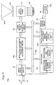
- Fig. 2 is a block diagram illustrating the general construction of the projector PJ.
- the projector PJ includes image input terminals 20 and 22, an image signal conversion circuit 30, a resolution conversion circuit 40, a projection size adjustment circuit 50, a liquid crystal panel actuation circuit 60, a liquid crystal panel 70, a lighting unit 80, a projection optical system 90, a controller 100, a projection size adjustment signal generation circuit 110, and a remote control circuit 120.
- the controller 100 is a microcomputer including a CPU and a memory (not shown) and controls the operations of the respective blocks 30 through 90, 110, and 120 via a bus 100b.
- the controller 100 executes programs stored in the non-illustrated memory to function as a resolution conversion control module 102 and a projection size control module 104 discussed later.
- the analog image input terminal 20 can receive a plurality of different analog image signals.
- Typical examples of such analog image signals include RGB signals output from a personal computer and composite image signals output from a video cassette recorder.
- the image signal conversion circuit 30 attains a diversity of functions, for example, function of analog-to-digital conversion, decoding function, function of synchronizing signal separation, and image processing function.
- the image signal conversion circuit 30 converts an analog image signal input into the analog image input terminal 20 to digital image data, and writes the converted digital image data into a frame memory (not shown) in the image signal conversion circuit 30 or reads the previously written digital image data from the frame memory synchronously with the synchronizing signal. Diverse series of image processing are carried out in the writing or reading process.
- the image signal conversion circuit 30 can also process digital image data input into the digital image input terminal 22. In such cases, a synchronizing signal is supplied independently of the digital image data, so that neither analog-digital conversion nor synchronizing signal separation is required.
- the image signal conversion circuit 30 includes a non-illustrated selection circuit, which selects one of the multiple image signals input into the image input terminals 20 and 22. Selection of the image signal is based on the user's specification of a desired image with the remote control RC or a panel switch (not shown) provided on the projector.
- the resolution conversion circuit 40 converts the resolution (number of pixels) of an image expressed by the input image signal into a resolution (number of pixels) acceptable by the liquid crystal panel 60.
- the projection size adjustment circuit 50 changes the resolution of the image expressed by the image data supplied from the resolution conversion circuit 40 to adjust the projection size. The series of processing executed by the resolution conversion circuit 40 and the projection size adjustment circuit 50 will be discussed in detail later.
- the resolution conversion control module 102 controls the operations of the resolution conversion circuit 40.
- the projection size control module 104 controls the operations of the projection size adjustment circuit 50, based on a size adjustment signal supplied from the projection size adjustment signal generation circuit 110.
- the projection size adjustment signal generation circuit 110 In response to the user's press of the switch SW1 for adjustment of the projection size, the projection size adjustment signal generation circuit 110 generates a size adjustment signal SAS and supplies the size adjustment signal SAS to the projection size control module 104. In response to the user's press of the switch SW2 on the remote control RC for adjustment of the projection size, the projection size adjustment signal generation circuit 110 is also actuated via the remote control circuit 120 to generate the size adjustment signal SAS.
- the image signal input into either of the image input terminals 20 and 22 is subjected to diverse series of image processing in the image signal conversion circuit 30, the resolution conversion circuit 40, and the projection size adjustment circuit 50 and is given to the liquid crystal panel actuation circuit 60.
- the liquid crystal panel actuation circuit 60 generates a driving signal for actuating the liquid crystal panel 70 according to the given image data.
- the liquid crystal panel 70 functions as a light valve (light modulator) that modulates illumination light emitted from the lighting unit 80 in response to the driving signal output from the liquid crystal panel actuation circuit 60 and thereby generates an image.
- the intensity of the illumination light emitted from the lighting unit 80 is regulated by the controller 100.
- the illumination light modulated by the liquid crystal panel 70 is output as light representing image (image light) toward the screen SCR by means of the projection optical system 90.
- a resulting projected image is then formed on the screen SCR.
- the projection magnification of the projection optical system 90 is regulated by the controller 100.
- the liquid crystal panel actuation circuit 60 and the liquid crystal panel 70 correspond to the image display device of he present invention.
- the image signal conversion circuit 30, the resolution conversion circuit 40, the projection size adjustment circuit 50, and the controller 100 correspond to the image signal processing module of the present invention.
- the liquid crystal panel actuation circuit 60 may not be part of the image display device but may be included in the image signal processing module.
- the liquid crystal panel 70 includes three liquid crystal panels corresponding to three colors R, G, and B.
- the image signal conversion circuit 30, the resolution conversion circuit 40, the projection size adjustment circuit 50, and the liquid crystal panel actuation circuit 60 respectively have the function of processing image signals of the three colors R, G, and B.
- the lighting unit 80 has a color light separation optical system to divide the light emitted from a light source into three color rays.
- the projection optical system 90 has a composition optical system and a projection lens that combines three color image rays into image light representing a color image. Any of the diverse known structures is applicable for the optical system of the projector.
- the user may use the remote control RC for various inputs.
- the signals output from the remote control RC are given to the controller 100 and the projection size adjustment signal generation circuit 110 via the remote control circuit 120 and are subjected to a diversity of processes.
- Fig. 3 shows conversion of the resolution carried out by the resolution conversion circuit 40.
- the resolution of an image expressed by an input image signal depends upon the type of the image supply device. For example, the number of pixels in the image expressed by the image signal supplied from the computer is 640 ⁇ 480 pixels in VGA, 800 ⁇ 600 pixels in SVGA, 1024 ⁇ 768 pixels in XGA, and 1280 ⁇ 1024 pixels in SXGA.
- the video signals supplied from video recorders and those from DVD (digital video disk) players also have different resolutions. Standard television signals and high resolution digital television signals have different resolutions.
- the liquid crystal panel 70 functioning as the image display device for the projector has, on the other hand, a fixed number of pixels.
- the resolution conversion circuit 40 thus expands or contracts the image of interest expressed by the input image signal to generate an image signal representing an expanded or contracted image having a specific number of pixels corresponding to the display area of the liquid crystal panel 70.
- the liquid crystal panel 70 has a number of horizontal pixels Px equal to 1024 and a number of vertical pixels Py equal to 768.
- the image expressed by the input image signal has a number of horizontal pixels OPx equal to 640 and a number of vertical pixels OPy equal to 480.
- a resolution conversion magnification ks is set equal to 1.6.
- the resolution conversion circuit 40 expands the image expressed by the input image signal by the preset resolution conversion magnification ks and thereby generates an image signal representing an image of a specific size equal to the size (Px ⁇ Py) of the image display area on the liquid crystal panel 70.
- the liquid crystal panel 70 has the number of horizontal pixels Px equal to 1024 and the number of vertical pixels Py equal to 768.
- the image expressed by the input image signal has the number of horizontal pixels OPx equal to 1280 and the number of vertical pixels OPy equal to 1024.
- the aspect ratio (the ratio of the number of horizontal pixels OPx to the number of vertical pixels OPy) of the image expressed by the input image signal is different from the aspect ratio (the ratio of the number of horizontal pixels Px to the number of vertical pixels Py) of the image display area on the liquid crystal panel 70.
- the magnification ks in the horizontal direction is 0.8
- the magnification ksv in the vertical direction is 0.75.
- the smaller magnification ksv in the vertical direction is set to the resolution conversion magnification ks.
- the resolution conversion circuit 40 contracts the image expressed by the input image signal by the preset resolution conversion magnification ks and thereby generates an image signal representing an image of a specific size substantially equal to the size (Px ⁇ Py) of the image display area on the liquid crystal panel 70.
- Contraction of the image is readily attained by any of diverse contraction processes, for example, a simple sampling process that maps multiple pixels of the original image to one representative pixel of the contracted image, a combined process of smoothing and simple sampling, or an averaging process that specifies the mean density of multiple pixels in the original image as a density value of one pixel in the contracted image.
- Expansion of the image is readily attained by any of diverse interpolation processes, for example, linear interpolation or weighted mean interpolation.
- the resolution conversion control module 102 can readily determine the resolution of the image expressed by the input image signal by specifying the input terminal that receives the input image signal or by specifying the type of the synchronizing signal, for example, the signal polarity or the signal frequency.
- the resolution conversion control module 102 selects the conversion magnification corresponding to the predetermined resolution, and sets the selected conversion magnification in the resolution conversion circuit 40 for conversion of the resolution.
- Fig. 4 shows adjustment of the projection size carried out by the projection size adjustment circuit 50.
- Fig. 4(A) shows projected images on the screen SCR.
- the projection factor kz is set in response to the user's press of the switch SW1 (see Fig. 1) of the projector PJ or the switch SW2 (see Fig. 1) of the remote control RC.
- the projection factor kz may be set in a range of 1 to 0.84 by a unit of 0.05.
- the setting of the projection factor kz is supplied as the size adjustment signal SAS from the projection size adjustment signal generation circuit 110 to the projection size control module 104.
- the projection size control module 104 controls the operations of the projection size adjustment circuit 50 based on the projection factor kz.
- the projection size adjustment circuit 50 outputs the image data supplied from the resolution conversion circuit 40 without any specific processing.
- the whole image display area of the liquid crystal panel 70 is actuated according to the image data of the input image signal to display a resulting image.
- the projection size control module 104 specifies an image area ZP for displaying a resulting image and a mask display area BP surrounding the image area ZP in the image display area MDA on the liquid crystal panel 70, based on the projection factor kz.
- the following describes a concrete procedure of specifying these areas ZP and BP.
- the contraction factor kzh in the horizontal direction and the contraction factor kzv in the vertical direction are set equal to the square root ⁇ n of the projection factor kz.
- the mask display area BP has the identical setting of the upper and lower widths as well as the identical setting of the left and right widths.
- the numbers of pixels in the horizontal direction and in the vertical direction in the image area ZP and in the mask display area BP thus determined are set in the projection size adjustment circuit 50.
- the projection size adjustment circuit 50 outputs black image data to the respective pixels of the liquid crystal panel 70 corresponding to the mask display area BP.
- the projection size adjustment circuit 50 contracts the image, which is expressed by the image data supplied from the resolution conversion circuit 40, based on the contraction factors kzh and kzv and outputs the image data of the contracted image to the respective pixels of the liquid crystal panel 70 corresponding to the image area ZP.
- the liquid crystal panel 70 is actuated according to the image data of the mask display area BP and the image area ZP output from the projection size adjustment circuit 50 to display an image.
- the projected image includes a black image part corresponding to the mask display area BP, so that only an image part corresponding to the image area ZP is actually displayed.
- the image part corresponding to the image area ZP is a contracted image based on the contraction factors kzh and kzv, that is, the projection factor kz.
- the projection size of the image is variable with the projection factor kz.
- the contraction technique executed in the resolution conversion circuit 40 is applicable for contraction of the image based on the contraction factors kzh and kzv, which is executed to make the projected image fit the image area ZP.
- the projector PJ of the embodiment is capable of readily adjusting the projection size by regulating the image area ZP for displaying the image expressed by the input image data and the mask display area BP surrounding the image area ZP for displaying the black image in the image display area MDA of the liquid crystal panel 70 according to the setting of the projection factor kz.
- Fig. 5 is a block diagram illustrating a modified structure of the projector PJ.
- a projector PJa of this modified example has a resolution conversion / projection size adjustment circuit 40A, which replaces the resolution conversion circuit 40 and the projection size adjustment circuit 50 shown in Fig. 2 and exerts the functions of these two elements.
- the resolution conversion / projection size adjustment circuit 40A uses either of factors (ks ⁇ kzh) and (ks ⁇ kzv), which are products of the contraction factors kzh and kzv in the projection size adjustment circuit 50 and the resolution conversion magnification ks in the resolution conversion circuit 40, to expand or contract the image expressed by the input image signal all at once and generate image data of the resulting image corresponding to the image area ZP.
- the projector PJa of the modified example is capable of readily adjusting the projection size by regulating the image area ZP for displaying the image expressed by the input image data and the mask display area BP surrounding the image area ZP for displaying the black image in the image display area MDA of the liquid crystal panel 70 according to the setting of the projection factor kz.
- the image expressed by the input image signal is expanded or contracted with the resolution conversion magnification ks.
- the subsequent projection size adjustment process contracts the image expressed by the resolution converted image signal to make the resolution converted image fit the size of the image area set according to the projection factor kz.
- One modified procedure may set the resolution conversion magnification ks equal to 1 and directly perform expansion or contraction of the projection size with the projection factor kz without conversion of the resolution.
- the image expressed by the input image data is expanded or contracted with the contraction factor kzh in the horizontal direction and the contraction factor kzv in the vertical direction based on the projection factor kz, so that the size-adjusted resulting image data fits the image area ZP.
- This arrangement allows the user to select execution or non-execution of the resolution conversion process.
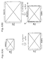
- Fig. 6 shows a displayed image when the image area ZP specified by the projection factor kz corresponding to the projection size is greater than the display area MDA of the liquid crystal panel 70.
- the projection size adjustment circuit 50 in the case where the setting of the image area ZP is greater than the image display area MDA on the liquid crystal panel 70, the projection size adjustment circuit 50 generates display image data to cause an image part corresponding to the size of the image display area MDA in the expanded image according to the size of the image area ZP to be displayed in the image display area MDA. Only the expanded image part set in the image display area MDA is accordingly displayed as shown in Fig. 6(B).
- the black image is applied for the image corresponding to the mask display area BP.
- the black image is, however, not restrictive in any sense.
- the image corresponding to the mask display area BP may be an image of any specific color other than black, for example, a white image or an image of the same color as that of the screen SCR.
- the projector of the present invention is effectively used to display images at presentations and to show motion pictures and guidance on board or in public spaces.
Landscapes
- Engineering & Computer Science (AREA)
- Multimedia (AREA)
- Signal Processing (AREA)
- Liquid Crystal Display Device Control (AREA)
- Controls And Circuits For Display Device (AREA)
- Control Of Indicators Other Than Cathode Ray Tubes (AREA)
- Projection Apparatus (AREA)
- Transforming Electric Information Into Light Information (AREA)
Abstract
Description
Claims (5)
- A projector that is capable of electronically adjusting a projection size of an image, said projector comprising:wherein said image processing module adjustably sets an image area on a center of an image display area of said image display device for displaying an image expressed by the input image signal and a mask display area surrounding the image area for displaying an image of a specific color, based on a user's setting of a parameter representing a projection size, said image processing module contracting or expanding the image expressed by the input image signal to make a size of the image expressed by the input image signal fit a size of the image area in the process of generating the display image signal from the input image signal, while generating the display image signal to make the image of the specific color displayed in the mask display area.an image display device that creates an image in response to a display image signal supplied thereto;an image signal processing module that generates the display image signal, which is to be supplied to said image display device, from an input image signal supplied from an image supply device; anda projection module that projects the image created by said image display device,
- A projector in accordance with claim 1, wherein said image processing module, when the size of the image expressed by the input image signal is different from a size of the image display area, expands or contracts the image expressed by the input image signal to make the size of the image expressed by the input image signal fit the size of the image display area to generate a resolution converted image signal, said image processing module subsequently contracting an image expressed by the resolution converted image signal to make a size of the image expressed by the resolution converted image signal fit the size of the image area.
- A projector in accordance with claim 1, wherein said image processing module, in the case where the size of the image area set based on the parameter is greater than a size of the image display area, generates the display image signal to cause an image part, which corresponds to the size of the image display area in an expanded image according to the size of the image area, to be displayed in the image display area.
- A projector in accordance with any one of claims 1 through 3, wherein the image of the specific color is a black image.
- A method of electronically adjusting a projection size of an image by a projector, said method comprising the steps of:adjustably setting an image area on a center of an image display area of an image display device included in said projector for displaying an image expressed by an input image signal and a mask display area surrounding the image area for displaying an image of a specific color, based on a user's setting of a parameter representing a projection size; and contracting or expanding the image expressed by the input image signal to make a size of the image expressed by the input image signal fit a size of the image area in the process of generating a display image signal from the input image signal, while generating the display image signal to make the image of the specific color displayed in the mask display area.
Applications Claiming Priority (3)
| Application Number | Priority Date | Filing Date | Title |
|---|---|---|---|
| JP2000394730 | 2000-12-26 | ||
| JP2000394730 | 2000-12-26 | ||
| PCT/JP2001/011406 WO2002052844A1 (en) | 2000-12-26 | 2001-12-25 | Projector and projection size adjusting method |
Publications (3)
| Publication Number | Publication Date |
|---|---|
| EP1347640A1 true EP1347640A1 (en) | 2003-09-24 |
| EP1347640A4 EP1347640A4 (en) | 2004-07-14 |
| EP1347640B1 EP1347640B1 (en) | 2006-08-30 |
Family
ID=18860313
Family Applications (1)
| Application Number | Title | Priority Date | Filing Date |
|---|---|---|---|
| EP01272321A Expired - Lifetime EP1347640B1 (en) | 2000-12-26 | 2001-12-25 | Projector and projection size adjusting method |
Country Status (7)
| Country | Link |
|---|---|
| US (1) | US7116379B2 (en) |
| EP (1) | EP1347640B1 (en) |
| JP (1) | JPWO2002052844A1 (en) |
| CN (1) | CN1264343C (en) |
| DE (1) | DE60122772T2 (en) |
| TW (1) | TW522278B (en) |
| WO (1) | WO2002052844A1 (en) |
Families Citing this family (32)
| Publication number | Priority date | Publication date | Assignee | Title |
|---|---|---|---|---|
| JP2002055669A (en) * | 2000-08-11 | 2002-02-20 | Nec Viewtechnology Ltd | Connected display device and method of connected displaying |
| JPWO2004021079A1 (en) * | 2002-08-29 | 2005-12-22 | ソニー株式会社 | Projection display |
| TWI222830B (en) * | 2003-03-26 | 2004-10-21 | Coretronic Corp | Image transmission system for rear projection television |
| US20070118812A1 (en) * | 2003-07-15 | 2007-05-24 | Kaleidescope, Inc. | Masking for presenting differing display formats for media streams |
| US7274382B2 (en) * | 2003-07-16 | 2007-09-25 | Plut William J | Customizable background sizes and controls for changing background size |
| US7928994B2 (en) * | 2003-07-16 | 2011-04-19 | Transpacific Image, Llc | Graphics items that extend outside a background perimeter |
| JP2005123707A (en) * | 2003-10-14 | 2005-05-12 | Casio Comput Co Ltd | Imaging projection apparatus and imaging projection system, display image generation apparatus, and display image generation method |
| US20070013873A9 (en) * | 2004-04-29 | 2007-01-18 | Jacobson Joseph M | Low cost portable computing device |
| WO2005112424A1 (en) * | 2004-05-19 | 2005-11-24 | Dstmedia Technology Co., Ltd. | Method for displaying image |
| CN1318884C (en) * | 2004-06-11 | 2007-05-30 | 明基电通股份有限公司 | How to adjust the light machine of the projector |
| US7461939B2 (en) * | 2004-11-19 | 2008-12-09 | Hewlett-Packard Development Company, L.P. | Automatic zoom for screen fitting |
| US20060250583A1 (en) * | 2005-05-05 | 2006-11-09 | Andrew Huibers | Multi-mode projectors with spatial light modulators |
| US7868847B2 (en) * | 2005-05-24 | 2011-01-11 | Mark W Miles | Immersive environments with multiple points of view |
| US20060274209A1 (en) * | 2005-06-03 | 2006-12-07 | Coretronic Corporation | Method and a control device using the same for controlling a display device |
| CN100349458C (en) * | 2005-07-12 | 2007-11-14 | 圆刚科技股份有限公司 | Digital video camera for presentations |
| US8174627B2 (en) * | 2005-09-06 | 2012-05-08 | Hewlett-Packard Development Company, L.P. | Selectively masking image data |
| JP5088665B2 (en) * | 2006-04-12 | 2012-12-05 | セイコーエプソン株式会社 | Image display device |
| US7787062B2 (en) * | 2006-05-19 | 2010-08-31 | Chunghwa Picture Tubes, Ltd. | Rear projection display and circuit and method for adjusting image thereof |
| JP4450014B2 (en) | 2007-05-30 | 2010-04-14 | セイコーエプソン株式会社 | Projector, image display device, and image processing device |
| FR2947063B1 (en) * | 2009-06-19 | 2011-07-01 | Commissariat Energie Atomique | OVERHEAD PROJECTOR |
| US8400468B2 (en) * | 2009-08-27 | 2013-03-19 | Seiko Epson Corporation | Projector masks for calibrating projector-based display systems |
| US9880619B2 (en) | 2010-02-23 | 2018-01-30 | Muy Interactive Ltd. | Virtual reality system with a finger-wearable control |
| CA2828222A1 (en) * | 2010-02-23 | 2011-09-01 | Muv Interactive Ltd. | A system for projecting content to a display surface having user-controlled size, shape and location/direction and apparatus and methods useful in conjunction therewith |
| US8506090B2 (en) * | 2010-03-22 | 2013-08-13 | Microvision, Inc. | Projection system with image orientation correction and corresponding method |
| US20110234921A1 (en) * | 2010-03-24 | 2011-09-29 | Victor Ivashin | Black-Level Compensation in Multi-Projector Display Systems |
| JP2012156797A (en) * | 2011-01-26 | 2012-08-16 | Sony Corp | Image processing apparatus and image processing method |
| US9389497B2 (en) | 2013-07-18 | 2016-07-12 | Tencent Technology (Shenzhen) Company Limited | Micro-projection-display devices and adjustable display screens |
| US10409366B2 (en) | 2014-04-28 | 2019-09-10 | Adobe Inc. | Method and apparatus for controlling display of digital content using eye movement |
| JP2016109841A (en) * | 2014-12-05 | 2016-06-20 | セイコーエプソン株式会社 | Display device and method for controlling display device |
| US10242379B2 (en) * | 2015-01-30 | 2019-03-26 | Adobe Inc. | Tracking visual gaze information for controlling content display |
| CN106773468B (en) * | 2016-11-30 | 2018-08-28 | 苏州佳世达光电有限公司 | The control method of projection arrangement and projection arrangement |
| CN109542381A (en) * | 2018-11-26 | 2019-03-29 | 努比亚技术有限公司 | Payment code display control method, mobile terminal and computer readable storage medium |
Family Cites Families (15)
| Publication number | Priority date | Publication date | Assignee | Title |
|---|---|---|---|---|
| US4392156A (en) * | 1981-05-04 | 1983-07-05 | Ampex Corporation | Video key edge generator for increasing the size of an associated border, drop shadow and/or outline |
| JPS6284665A (en) | 1985-10-09 | 1987-04-18 | Matsushita Electric Ind Co Ltd | television receiver |
| JP3152396B2 (en) * | 1990-09-04 | 2001-04-03 | 株式会社東芝 | Medical image display device |
| JPH04175742A (en) | 1990-11-09 | 1992-06-23 | Sharp Corp | Liquid crystal projection device |
| JPH04365280A (en) | 1991-06-13 | 1992-12-17 | Matsushita Electric Ind Co Ltd | Projecting image display device |
| US5285268A (en) * | 1991-12-10 | 1994-02-08 | Victor Company Of Japan, Ltd. | Projection type display device having a mask for cutting off unnecessary light parts of displayed picture |
| JPH05323451A (en) | 1992-05-18 | 1993-12-07 | Victor Co Of Japan Ltd | Video projector device |
| US5347318A (en) * | 1992-06-16 | 1994-09-13 | Canon Kabushiki Kaisha | Apparatus for processing video signals having different aspect ratios |
| JPH06334947A (en) | 1993-05-26 | 1994-12-02 | Mitsubishi Electric Corp | Video projector |
| US5721565A (en) * | 1994-04-29 | 1998-02-24 | Proxima Corporation | Zooming protection display control system and method of using same |
| JP3329070B2 (en) | 1994-05-31 | 2002-09-30 | 松下電器産業株式会社 | Projection display device |
| JPH1188806A (en) | 1997-09-02 | 1999-03-30 | Toshiba Corp | LCD projector with document camera |
| JPH1184530A (en) | 1997-09-03 | 1999-03-26 | Victor Co Of Japan Ltd | Projector device |
| JPH1195324A (en) | 1997-09-19 | 1999-04-09 | Fujitsu General Ltd | Simple screen size adjustment projector |
| JP3613985B2 (en) | 1998-06-29 | 2005-01-26 | セイコーエプソン株式会社 | Image processing apparatus and projection display apparatus |
-
2001
- 2001-12-25 WO PCT/JP2001/011406 patent/WO2002052844A1/en not_active Ceased
- 2001-12-25 DE DE60122772T patent/DE60122772T2/en not_active Expired - Lifetime
- 2001-12-25 TW TW090132212A patent/TW522278B/en not_active IP Right Cessation
- 2001-12-25 US US10/220,358 patent/US7116379B2/en not_active Expired - Lifetime
- 2001-12-25 EP EP01272321A patent/EP1347640B1/en not_active Expired - Lifetime
- 2001-12-25 JP JP2002553819A patent/JPWO2002052844A1/en active Pending
- 2001-12-25 CN CNB018055494A patent/CN1264343C/en not_active Expired - Lifetime
Also Published As
| Publication number | Publication date |
|---|---|
| DE60122772T2 (en) | 2007-09-20 |
| JPWO2002052844A1 (en) | 2004-04-30 |
| CN1264343C (en) | 2006-07-12 |
| CN1406434A (en) | 2003-03-26 |
| US7116379B2 (en) | 2006-10-03 |
| EP1347640B1 (en) | 2006-08-30 |
| TW522278B (en) | 2003-03-01 |
| DE60122772D1 (en) | 2006-10-12 |
| EP1347640A4 (en) | 2004-07-14 |
| US20030020885A1 (en) | 2003-01-30 |
| WO2002052844A1 (en) | 2002-07-04 |
Similar Documents
| Publication | Publication Date | Title |
|---|---|---|
| EP1347640B1 (en) | Projector and projection size adjusting method | |
| US7233370B2 (en) | Method for correcting for distortion of projected image, program for correcting image distortion, and projection-type image display device | |
| US6914616B2 (en) | Image reproduction display apparatus utilizing a controller with selection mask conversion module | |
| US7093940B2 (en) | Adjustment in the amount of projected image distortion correction | |
| JP2005215542A (en) | Video projector apparatus and projected image position adjustment method | |
| JP2017198742A (en) | Projection device and control method of the same, as well as projection system | |
| US6642971B2 (en) | Image display apparatus, method of displaying images, image processing apparatus, and method of processing images | |
| JP5217194B2 (en) | projector | |
| US7030867B2 (en) | Image processing device for adjusting characteristic data based on reference image and image display apparatus using the same | |
| JP2002196736A (en) | Projection size adjustment of projector according to aspect ratio | |
| CN208903641U (en) | Projection device | |
| JP3700623B2 (en) | Projection-type image display device | |
| JPH0981079A (en) | Projection equipment | |
| JP2009294349A (en) | Projector having image adjusting function | |
| JPH05313116A (en) | Projector | |
| JPH09304749A (en) | Projection image display | |
| JP2008098693A (en) | Projector, program thereof and recording medium | |
| JP2005268838A (en) | Video display device and video display control device | |
| JP2019208169A (en) | Projection apparatus, control method of the same, program, and storage medium | |
| JP2001209351A (en) | Projection type video display device | |
| JPH04365280A (en) | Projecting image display device | |
| JP2024010940A (en) | Projection display device, projection display system, control method for projection display device, and program | |
| JP2024070341A (en) | Projection display device, projection display system, control method for projection display device, and program | |
| JPH03139622A (en) | Projection type image display device | |
| JP3383013B2 (en) | Projector equipment |
Legal Events
| Date | Code | Title | Description |
|---|---|---|---|
| PUAI | Public reference made under article 153(3) epc to a published international application that has entered the european phase |
Free format text: ORIGINAL CODE: 0009012 |
|
| 17P | Request for examination filed |
Effective date: 20021218 |
|
| AK | Designated contracting states |
Kind code of ref document: A1 Designated state(s): AT BE CH CY DE DK ES FI FR GB GR IE IT LI LU MC NL PT SE TR |
|
| AX | Request for extension of the european patent |
Extension state: AL LT LV MK RO SI |
|
| RBV | Designated contracting states (corrected) |
Designated state(s): AT BE CH DE FR GB LI |
|
| A4 | Supplementary search report drawn up and despatched |
Effective date: 20040601 |
|
| 17Q | First examination report despatched |
Effective date: 20050614 |
|
| GRAP | Despatch of communication of intention to grant a patent |
Free format text: ORIGINAL CODE: EPIDOSNIGR1 |
|
| RBV | Designated contracting states (corrected) |
Designated state(s): DE FR GB |
|
| GRAS | Grant fee paid |
Free format text: ORIGINAL CODE: EPIDOSNIGR3 |
|
| GRAA | (expected) grant |
Free format text: ORIGINAL CODE: 0009210 |
|
| AK | Designated contracting states |
Kind code of ref document: B1 Designated state(s): DE FR GB |
|
| REG | Reference to a national code |
Ref country code: GB Ref legal event code: FG4D |
|
| REF | Corresponds to: |
Ref document number: 60122772 Country of ref document: DE Date of ref document: 20061012 Kind code of ref document: P |
|
| ET | Fr: translation filed | ||
| PG25 | Lapsed in a contracting state [announced via postgrant information from national office to epo] |
Ref country code: DE Free format text: LAPSE BECAUSE OF NON-PAYMENT OF DUE FEES Effective date: 20070703 |
|
| PLBE | No opposition filed within time limit |
Free format text: ORIGINAL CODE: 0009261 |
|
| STAA | Information on the status of an ep patent application or granted ep patent |
Free format text: STATUS: NO OPPOSITION FILED WITHIN TIME LIMIT |
|
| 26N | No opposition filed |
Effective date: 20070531 |
|
| PGRI | Patent reinstated in contracting state [announced from national office to epo] |
Ref country code: DE Effective date: 20071119 |
|
| REG | Reference to a national code |
Ref country code: FR Ref legal event code: PLFP Year of fee payment: 15 |
|
| REG | Reference to a national code |
Ref country code: FR Ref legal event code: PLFP Year of fee payment: 16 |
|
| REG | Reference to a national code |
Ref country code: FR Ref legal event code: PLFP Year of fee payment: 17 |
|
| PGFP | Annual fee paid to national office [announced via postgrant information from national office to epo] |
Ref country code: DE Payment date: 20201216 Year of fee payment: 20 Ref country code: FR Payment date: 20201112 Year of fee payment: 20 Ref country code: GB Payment date: 20201216 Year of fee payment: 20 |
|
| REG | Reference to a national code |
Ref country code: DE Ref legal event code: R071 Ref document number: 60122772 Country of ref document: DE |
|
| REG | Reference to a national code |
Ref country code: GB Ref legal event code: PE20 Expiry date: 20211224 |
|
| PG25 | Lapsed in a contracting state [announced via postgrant information from national office to epo] |
Ref country code: GB Free format text: LAPSE BECAUSE OF EXPIRATION OF PROTECTION Effective date: 20211224 |