EP1347525A1 - Gas diffusive electrode, electroconductive ion conductor, their manufacturing method, and electrochemical device - Google Patents
Gas diffusive electrode, electroconductive ion conductor, their manufacturing method, and electrochemical device Download PDFInfo
- Publication number
- EP1347525A1 EP1347525A1 EP01272912A EP01272912A EP1347525A1 EP 1347525 A1 EP1347525 A1 EP 1347525A1 EP 01272912 A EP01272912 A EP 01272912A EP 01272912 A EP01272912 A EP 01272912A EP 1347525 A1 EP1347525 A1 EP 1347525A1
- Authority
- EP
- European Patent Office
- Prior art keywords
- electrically conductive
- ionic conductor
- group
- gas diffusion
- diffusion electrode
- Prior art date
- Legal status (The legal status is an assumption and is not a legal conclusion. Google has not performed a legal analysis and makes no representation as to the accuracy of the status listed.)
- Withdrawn
Links
Images


Classifications
-
- H—ELECTRICITY
- H01—ELECTRIC ELEMENTS
- H01M—PROCESSES OR MEANS, e.g. BATTERIES, FOR THE DIRECT CONVERSION OF CHEMICAL ENERGY INTO ELECTRICAL ENERGY
- H01M4/00—Electrodes
- H01M4/86—Inert electrodes with catalytic activity, e.g. for fuel cells
- H01M4/96—Carbon-based electrodes
-
- H—ELECTRICITY
- H01—ELECTRIC ELEMENTS
- H01M—PROCESSES OR MEANS, e.g. BATTERIES, FOR THE DIRECT CONVERSION OF CHEMICAL ENERGY INTO ELECTRICAL ENERGY
- H01M4/00—Electrodes
- H01M4/86—Inert electrodes with catalytic activity, e.g. for fuel cells
-
- C—CHEMISTRY; METALLURGY
- C09—DYES; PAINTS; POLISHES; NATURAL RESINS; ADHESIVES; COMPOSITIONS NOT OTHERWISE PROVIDED FOR; APPLICATIONS OF MATERIALS NOT OTHERWISE PROVIDED FOR
- C09C—TREATMENT OF INORGANIC MATERIALS, OTHER THAN FIBROUS FILLERS, TO ENHANCE THEIR PIGMENTING OR FILLING PROPERTIES ; PREPARATION OF CARBON BLACK ; PREPARATION OF INORGANIC MATERIALS WHICH ARE NO SINGLE CHEMICAL COMPOUNDS AND WHICH ARE MAINLY USED AS PIGMENTS OR FILLERS
- C09C1/00—Treatment of specific inorganic materials other than fibrous fillers; Preparation of carbon black
- C09C1/44—Carbon
- C09C1/48—Carbon black
- C09C1/56—Treatment of carbon black ; Purification
-
- H—ELECTRICITY
- H01—ELECTRIC ELEMENTS
- H01M—PROCESSES OR MEANS, e.g. BATTERIES, FOR THE DIRECT CONVERSION OF CHEMICAL ENERGY INTO ELECTRICAL ENERGY
- H01M4/00—Electrodes
- H01M4/86—Inert electrodes with catalytic activity, e.g. for fuel cells
- H01M4/8605—Porous electrodes
-
- H—ELECTRICITY
- H01—ELECTRIC ELEMENTS
- H01M—PROCESSES OR MEANS, e.g. BATTERIES, FOR THE DIRECT CONVERSION OF CHEMICAL ENERGY INTO ELECTRICAL ENERGY
- H01M4/00—Electrodes
- H01M4/86—Inert electrodes with catalytic activity, e.g. for fuel cells
- H01M4/8647—Inert electrodes with catalytic activity, e.g. for fuel cells consisting of more than one material, e.g. consisting of composites
- H01M4/8652—Inert electrodes with catalytic activity, e.g. for fuel cells consisting of more than one material, e.g. consisting of composites as mixture
-
- H—ELECTRICITY
- H01—ELECTRIC ELEMENTS
- H01M—PROCESSES OR MEANS, e.g. BATTERIES, FOR THE DIRECT CONVERSION OF CHEMICAL ENERGY INTO ELECTRICAL ENERGY
- H01M4/00—Electrodes
- H01M4/86—Inert electrodes with catalytic activity, e.g. for fuel cells
- H01M4/88—Processes of manufacture
- H01M4/8803—Supports for the deposition of the catalytic active composition
- H01M4/8807—Gas diffusion layers
-
- H—ELECTRICITY
- H01—ELECTRIC ELEMENTS
- H01M—PROCESSES OR MEANS, e.g. BATTERIES, FOR THE DIRECT CONVERSION OF CHEMICAL ENERGY INTO ELECTRICAL ENERGY
- H01M4/00—Electrodes
- H01M4/86—Inert electrodes with catalytic activity, e.g. for fuel cells
- H01M4/88—Processes of manufacture
- H01M4/8825—Methods for deposition of the catalytic active composition
- H01M4/8867—Vapour deposition
-
- H—ELECTRICITY
- H01—ELECTRIC ELEMENTS
- H01M—PROCESSES OR MEANS, e.g. BATTERIES, FOR THE DIRECT CONVERSION OF CHEMICAL ENERGY INTO ELECTRICAL ENERGY
- H01M4/00—Electrodes
- H01M4/86—Inert electrodes with catalytic activity, e.g. for fuel cells
- H01M4/90—Selection of catalytic material
- H01M4/92—Metals of platinum group
- H01M4/925—Metals of platinum group supported on carriers, e.g. powder carriers
- H01M4/926—Metals of platinum group supported on carriers, e.g. powder carriers on carbon or graphite
-
- H—ELECTRICITY
- H01—ELECTRIC ELEMENTS
- H01M—PROCESSES OR MEANS, e.g. BATTERIES, FOR THE DIRECT CONVERSION OF CHEMICAL ENERGY INTO ELECTRICAL ENERGY
- H01M8/00—Fuel cells; Manufacture thereof
- H01M8/10—Fuel cells with solid electrolytes
- H01M8/1004—Fuel cells with solid electrolytes characterised by membrane-electrode assemblies [MEA]
-
- C—CHEMISTRY; METALLURGY
- C01—INORGANIC CHEMISTRY
- C01P—INDEXING SCHEME RELATING TO STRUCTURAL AND PHYSICAL ASPECTS OF SOLID INORGANIC COMPOUNDS
- C01P2006/00—Physical properties of inorganic compounds
- C01P2006/40—Electric properties
-
- Y—GENERAL TAGGING OF NEW TECHNOLOGICAL DEVELOPMENTS; GENERAL TAGGING OF CROSS-SECTIONAL TECHNOLOGIES SPANNING OVER SEVERAL SECTIONS OF THE IPC; TECHNICAL SUBJECTS COVERED BY FORMER USPC CROSS-REFERENCE ART COLLECTIONS [XRACs] AND DIGESTS
- Y02—TECHNOLOGIES OR APPLICATIONS FOR MITIGATION OR ADAPTATION AGAINST CLIMATE CHANGE
- Y02E—REDUCTION OF GREENHOUSE GAS [GHG] EMISSIONS, RELATED TO ENERGY GENERATION, TRANSMISSION OR DISTRIBUTION
- Y02E60/00—Enabling technologies; Technologies with a potential or indirect contribution to GHG emissions mitigation
- Y02E60/30—Hydrogen technology
- Y02E60/50—Fuel cells
-
- Y—GENERAL TAGGING OF NEW TECHNOLOGICAL DEVELOPMENTS; GENERAL TAGGING OF CROSS-SECTIONAL TECHNOLOGIES SPANNING OVER SEVERAL SECTIONS OF THE IPC; TECHNICAL SUBJECTS COVERED BY FORMER USPC CROSS-REFERENCE ART COLLECTIONS [XRACs] AND DIGESTS
- Y02—TECHNOLOGIES OR APPLICATIONS FOR MITIGATION OR ADAPTATION AGAINST CLIMATE CHANGE
- Y02P—CLIMATE CHANGE MITIGATION TECHNOLOGIES IN THE PRODUCTION OR PROCESSING OF GOODS
- Y02P70/00—Climate change mitigation technologies in the production process for final industrial or consumer products
- Y02P70/50—Manufacturing or production processes characterised by the final manufactured product
Definitions
- the present invention relates to a gas diffusion electrode, an electrically conductive ionic conductor, a method of producing the same, and an electrochemical device.
- a gas diffusion electrode As an electrode in an electrochemical device such as a fuel cell, a gas diffusion electrode is used.
- the gas diffusion electrode is produced through a process that catalyst particles made of platinum supported on carbon as a catalyst mixed with a water-repellent resin such as a fluorocarbon resin, etc. and an ionic conductor is formed into a sheet shape (Japanese Unexamined Patent Application Publication No. Hei 5-36418), or a process that the catalyst particles are applied on a carbon sheet.
- the gas diffusion electrode When the gas diffusion electrode are used as an electrode for hydrogen decomposition in a fuel cell such as a solid polymer type fuel cell, in the electrode, a hydrogen fuel (H 2 ) in the form of gas applied to the electrode is ionized by a platinum catalyst, then generated electrons flow through carbon, and protons (H + ) generated from hydrogen flow into an ion conductive film via an ionic conductor. Therefore, such an electrode requires an electrically conductive material such as carbon, a catalyst for ionizing a fuel or an oxidizer, and an ionic conductor as components, and gaps for conducting a gas therethrough.
- a hydrogen fuel (H 2 ) in the form of gas applied to the electrode is ionized by a platinum catalyst, then generated electrons flow through carbon, and protons (H + ) generated from hydrogen flow into an ion conductive film via an ionic conductor. Therefore, such an electrode requires an electrically conductive material such as carbon, a catalyst for ionizing a fuel or an
- a solution containing ionized platinum is prepared, and after carbon power is immersed in the solution, reduction and heat treatment are carried out. Thereby, catalyst particles which are platinum in a fine-particle shape deposited on the carbon power are formed. Next, the catalyst particles are mixed with the ionic conductor, and then the mixture is kneaded and applied. Thus, an electrode mixedly comprising the ionic conductor, the electrically conductive powder and the catalyst is formed (Japanese Patent No. 2879649).
- the platinum catalyst is covered with the ionic conductor, so almost no contact area with a supplied gas is present.
- the platinum. catalyst functions as a catalyst only in part which contacts with the gas, in such a state that the gas is blocked by the ionic conductor, the platinum catalyst cannot effectively function.
- an object of the present invention to provide an electrically conductive ionic conductor and a gas diffusion electrode capable of having electronic conductivity and ion conductivity, a method of producing the same, and an electrochemical device.
- An electrically conductive ionic conductor according to the present invention comprises electrically conductive powder having an ion conductive group bonded thereto, or electrically conductive powder having an ionic conductor deposited thereon. Further, a gas diffusion electrode according to the invention comprises the electrically conductive ionic conductor of the invention.
- a method of producing an electrically conductive ionic conductor according to the invention comprises the step of bonding an ion conductive group to electrically conductive powder by chemical treatment; or depositing an ion conductor on electrically conductive powder. Further, a method of producing a gas diffusion electrode according to the invention comprises the step of containing at least a catalyst in the electrically conductive ionic conductor of the invention.
- an electrochemical device comprises a positive electrode and a negative electrode, wherein at least one of the positive electrode and the negative electrode is the gas diffusion electrode according to the invention.
- the electrically conductive ionic conductor according to the invention has electronic conductivity and ion conductivity, so ions such as electrons and protons (H + ) can be effectively conducted.
- the gas diffusion electrode according to the invention comprises the electrically conductive ionic conductor of the invention, so another ionic conductor is not required as an electrode material, and generated ions such as electrons and protons (H + ) can be effectively conducted.
- the gas contact area of the catalyst will become larger.
- the ion conductive group is bonded to the electrically conductive powder through chemical treatment, so the ion conductive group is stably maintained in the produced electrically conductive ionic conductor.
- At least one of the positive electrode and the negative electrode is the gas diffusion electrode of the invention, so the efficiency of electrode reaction can be improved, and the output properties can be substantially improved.
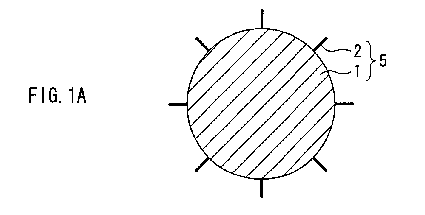
- FIG. 1A shows a cross-sectional view of an electrically conductive ionic conductor 5 according to the embodiment of the invention.
- the electrically conductive ionic conductor 5 is comprised by adding an ion conductive group 2 to electrically conductive powder 1 by a chemical bond, so the electrically conductive ionic conductor 5 has electronic conductivity and ion conductivity. Therefore, when the electrically conductive ionic conductor 5 is used, for example, as a material of a gas diffusion electrode used for a fuel cell, etc., electrons or hydrogen ions in the electrode can be smoothly conducted.
- the ion conductive group 2 is simply deposited on the electrically conductive powder 1, the ion conductive group 2 is easily removed from the electrically conductive powder 1, although in this case, the ion conductive group 2 is bonded through chemical treatment, so the state that the ion conductive group 2 is added to the electrically conductive powder 1 is stably maintained.
- the particle diameter of the electrically conductive powder 1 is preferably within a range from 1 nm to 10 nm, and in terms of a reduction in the internal resistance of a cell, the electrical resistance thereof is preferably 10 -3 ⁇ ⁇ m or less.
- the electrically conductive powder for example, at least one kind selected from the group consisting of carbon, ITO (indium tin oxide: a conductive oxide which is indium oxide doped with tin) and tin oxide can be used.
- ITO indium tin oxide: a conductive oxide which is indium oxide doped with tin
- carbon there is acetylene black, a carbon nanotube (CNT) or a carbon fiber (CF), etc.
- the oil absorption is 200 ml/100 g or over (the specific surface area is 300 m 2 /g or over).
- a carbon nanotube and a carbon fiber having a larger surface area and higher electronic conductivity are preferably used.
- the electronic conductivity of the electrically conductive powder 1 may be impaired, so the amount of bonding is required to be adjusted as necessary.
- the bonding amount of the ion conductive group 2 to the electrically conductive powder 1 through chemical treatment is preferably within a range from 0.001 mol to 0.3 mol per mol of the material of the electrically conductive powder 1.
- the bonding amount of the ion conductive group 2 is preferably within a range from 0.001 mol to 0.1 mol, more preferably from 0.003 mol to 0.05 mol, and most preferably from 0.005 mol to 0.02 mol per mol of the electrically conductive powder 1.
- the bonding amount of the ion conductive group 2 is preferably within a range from 0.001 mol to 0.3 mol, more preferably from 0.01 mol to 0.15 mol, and most preferably 0.015 mol to 0.06 mol per mol of the electrically conductive powder 1.
- the bonding amount of the ion conductive group 2 to the electrically conductive powder 1 is less than the above range, sufficient in conductivity may not be able to be obtained.
- the bonding amount is more than the above range, higher ion conductivity can be obtained, although electronic conductivity may be impaired.
- the ion conductive group 2 is preferably a proton dissociation group, for example, any one selected from the group consisting of -OH, -OSO 3 H, COOH, -SO 3 H and -OPO(OH) 2 .
- a term "proton dissociation group” herein means a functional group from which protons can be dissociated through ionization, and a term “dissociation of proton (H + )" means that protons are dissociated from the functional group through ionization.
- Such an electrically conductive ionic conductor 5 can be a material of, for example, a gas diffusion electrode.
- a catalyst for ionizing a fuel gas is preferably deposited on a surface of the electrically conductive ionic conductor 5.
- the catalyst is preferably deposited at a rate of 10% by weight to 1000% by weight of the electrically conductive ionic conductor 5. Further, the catalyst is preferably metal having electronic conductivity, such as platinum, ruthenium, vanadium, tungsten, etc. or a mixture thereof.
- a method of depositing the catalyst on the electrically conductive ionic conductor 5 is not specifically limited.
- thermal reduction treatment in order to achieve high crystallinity of a catalyst 3, thermal reduction treatment must be carried out, but the ion conductive group 2 generally has low heat resistance, so the ion conductive group 2 may suffer deterioration due to heating. Therefore, physical vapor deposition such as a sputtering method, a pulse laser deposition (PLD) method or a vacuum evaporation method, etc. is preferably used.
- FIG. 1B shows an illustration of the electrically conductive ionic conductor in a state that the catalyst is deposited on a surface thereof through the physical vapor deposition.
- the catalyst 3 with higher crystallinity can be deposited on the surface of the electrically conductive ionic conductor 5 at a lower temperature without impairing the performance of the ion conductive group 2.
- the catalyst 3 in a spherical shape is deposited on the electrically conductive ionic conductor 5, and on the other hand, in the case of the physical vapor deposition, the catalyst 3 is deposited so as to coat particles of the electrically conductive ionic conductor 5, thereby better catalysis can be obtained by a smaller amount of catalyst.
- the specific surface area of the catalyst 3 becomes larger, so that the catalytic activities are improved.
- the catalyst 3 may be unevenly coated on the surface of the electrically conductive ionic conductor 5. Even in this case, the same effects and advantages as those of the powder shown in FIG. 1B can be obtained.
- the sputtering method allows easier production, so the productivity is higher, and the film-forming properties are better. Also, in the pulse laser deposition method, it is easy to control film deposition, so the film-forming properties are better.
- vibrations are preferably applied to the electrically conductive ionic conductor 5 so as to sufficiently and evenly deposit the catalyst 3 thereon.
- a mechanism for creating vibrations is not specifically limited, but, for example, sonic waves are preferably applied to create vibrations.
- FIG. 2 shows an illustration for explaining a step of applying vibrations to the electrically conductive ionic conductor when the catalyst is deposited on the surface of the electrically conductive ionic conductor through the sputtering method.
- platinum (Pt) as the catalyst 3 is supplied from a Pt target 4 to be deposited on the surface of the electrically conductive ionic conductor 5 to which vibrations are applied by an ultrasonic transducer 6.
- the vibration frequency of the ultrasonic transducer 6 is, for example, 40 kHz, but it may be a lower frequency, that is, on the order of a few tens of Hz (for example, 30 to 40 Hz).
- the catalyst 3 deposited on the electrically conductive ionic conductor 5 is bound by, for example, a resin, and molded to form a gas diffusion electrode.
- the obtained gas diffusion electrode can be suitably used for various electrochemical devices such as a fuel cell, etc.
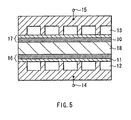
- FIG. 5 shows an illustration of the structure of a fuel cell according to the embodiment of the invention.
- the fuel cell comprises an ion conductive portion 18 disposed between a negative electrode (fuel electrode or hydrogen electrode) 16 and a positive electrode (oxygen electrode) 17 facing each other. Further, a H 2 flow path 12 and a terminal 14 led out from the electrode 16, and a O 2 flow path 13 and a terminal 15 led out from the electrode 17 are disposed on the opposite sides of surfaces of the negative electrode 16 and the positive electrode 17 facing each other, respectively.
- both of the negative electrode 16 and the positive electrode 17 are the above gas diffusion electrodes, however, at least the negative electrode 16 may be the gas diffusion electrode.
- Each of the electrodes 16 and 17, that is, the gas diffusion electrode according to the embodiment comprises a catalyst layer 10 and a porous gas permeable current collector 11 such as a carbon sheet, etc.
- the catalyst layer 10 includes powder made through depositing the catalyst 3 (for example, platinum) on the surface of the electrically conductive ionic conductor 5 (for example, a material made of carbon powder having a sulfonic acid group chemically bonded thereto) and a mixture of a water repellent resin (for example, a fluorine-based) and a pore-forming agent (for example, CaCO 3 ).
- the catalyst layer 10 may include only powder made of the above electrically conductive ionic conductor 5 having the catalyst 3 deposited thereon, or may include any other ingredients such as a binder or an ion conductive material. Further, the gas permeable current collector 11 is not necessarily required.
- Nafion DuPont's perfluorinated sulfonic acid resin
- a fullerene derivative such as fullerenol (polyhydroxylated fullerene), etc. may be used.
- the fullerene derivative has protonic (H + ) conductivity, therefore, the fullerene derivative can be included in the electrodes 16 and 17 in addition to the ion conductive portion 18.
- FIGs. 3A and 3B show the structures of fullerenol formed by introducing a plurality of hydroxyl groups (OH groups) into fullerene.
- OH groups hydroxyl groups
- the inventor discovered for the first time that when fullerenol formed an agglomerate as schematically shown in FIG. 4A so as to generate interaction between hydraxyl groups of fullerenol (in the drawing, "o" indicates fullerene) adjacent to each other, the agglomerate exhibited higher protonic conductivity (in other words, dissociation of H + from a phenolic hydroxyl group) as a macro aggregate.
- the material of the ion conductive portion 18 does not limited to fullerenol and hydrogensulfate esterified fullerenol, but any fullerene derivatives which can develop the protonic conductivity are applicable. Therefore, the groups introduced into fullerene are not specifically limited to the OSO 3 H groups and the OH groups, and, for example, -COOH, -SO 3 H and -OPO(OH) 2 , etc. can be introduced.
- fullerene as a matrix can introduce a large number of functional groups such as the OH groups and the OSO 3 H groups into a molecule, so when a large number of fullerene derivatives are agglomerated, the hydrogen ion density per unit volume becomes extremely high so that effective conductivity can be developed.
- fullerene has electrophilicity, it is considered that in fullerene derivatives, the ionization of hydrogen ion in not only the OSO 3 H groups with high acidity but also the OH groups or the like is promoted so as to make the protonic conductivity higher.
- fullerene derivatives are mostly made of carbon atoms of fullerene, so they are lightweight and resistant to deterioration, and have no contaminant.
- the producing cost of fullerene has been steeply reduced. Consequently, it can be considered that fullerene is superior in material properties, as well as is an ideal electrolyte material in terms of resource, environment and economy.
- fullerene powder An appropriate combination of well-known treatment such as acid treatment and hydrolysis is carried out on fullerene powder to introduce desired groups into carbon atoms of fullerene, thereby these fullerene derivatives are prepared. Then, the obtained fullerene derivatives are formed into a film shape through pressing, extrusion, or a well-known film forming method such as coating or vapor deposition, so that the ion conductive portion 18 can be formed. At this time, the ion conductive portion 18 may be virtually made of only fullerene derivatives or may include a binder.
- the binder one or more kinds of well-known polymers with film-forming property can be used, and the composition amount of the binder in the ion conductive portion 18 can be limited to 20% by weight or less in general. When the amount exceeds 20% by weight, the protonic conductivity may decline.
- the film-forming property derived from the binder is added, and a flexible ion conductive thin film (generally 300 ⁇ m thick or less) with a higher strength and a gas-permeation resistant function can be formed, compared with a powder compression molding of fullerene derivatives.
- the above polymeric material is not specifically limited, and any materials having as little loss of protonic conductivity (due to the reaction with the fullerene derivatives) as possible and a film-forming property may be used.
- a material having no electronic conductivity, and having good stability is used.
- Specific examples of the material are polytetrafluoroethylene, polyvinylidene fluoride, polyvinyl alcohol and so on, which are preferable polymeric materials because of the following reasons.
- polytetrafluoroethylene is preferable, because a thin film having a higher strength can be easily formed with a small composition amount thereof, compared with other polymeric materials.
- the composition amount is as small as 3% by weight or less, preferably 0.5% by weight to 1.5% by weight, so that the thickness of the thin film can be as thin as 100 ⁇ m to 1 ⁇ m in general.
- composition amount is preferably within a range from 5% by weight to 15% by weight.
- composition amount when the composition amount is less than the lower limit of the above range, it may have adverse effects on forming a film.
- binders can be used as water repellent resins which can be included in the electrodes 16 and 17.
- H 2 hydrogen (H 2 ) or a hydrogen-contained gas is passed through the H 2 flow path 12
- oxygen (air) or an oxygen-contained gas is passed through the O 2 flow path 13
- H 3 O + ions or H + ions are generated in the negative electrode 16 during the time when H 2 is passed through the flow path 12, and the ions are conducted into the positive electrode 17 via the ion conductive portions 18 so as to react with oxygen (air) or the oxygen-contained gas passing through the O 2 flow path 13.
- a desired electromotive force can be obtained from between the terminals 14 and 15 of the electrodes 16 and 17, respectively.
- the electrodes 16 and 17 are gas diffusion electrodes according to the embodiment, so conduction of electrons and ions relate to the electrode reaction in the electrodes is smoothly progressed. Further, the electrodes 16 and 17 have electronic conductivity and ion conductivity, so it is not required to further dispose an ionic conductor on the surfaces thereof, and a contact area between the catalyst 3 and the gas is large, thereby, better catalytic activities can be obtained.
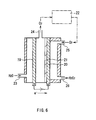
- FIG. 6 shows a cross-sectional view of a hydrogen peroxide producing apparatus according to the embodiment.
- Hydrogen peroxide can be obtained through a non-electrolysis method, although an on-site method of producing hydrogen peroxide is more favorable for, for example, a bleaching process in a pulp factory.
- the hydrogen peroxide producing apparatus comprises an anode 19 and a cathode 20 facing each other, and a protonic conductive portion 21 disposed therebetween.
- a O 2 outlet 24 for discharging oxygen is disposed, and on the opposite side of the surface of the anode 19, a H 2 O inlet 23 for supplying water or a water-containing liquid (for example, a solution including sodium hydroxide as an electrolyte) is disposed.
- a sodium hydroxide solution as the water-containing liquid is generally used in a concentration of 0.5 mol/l to 1 mol/l.
- the protonic conductive portion 21 On the side of a surface of the cathode 19 facing the anode 19, the protonic conductive portion 21 is disposed, and on the opposite side of the surface thereof, a O 2 inlet 25 for supplying oxygen or a oxygen-containing gas and a H 2 O 2 takeout opening 26 for taking generated hydrogen peroxide out.
- the cathode 20 of two electrodes 19 and 20 is the above gas diffusion electrode.
- the anode 19 comprises, for example, platinum deposited on a porous carbon sheet.
- the protonic conductive portion 21 separates the both electrodes 19 and 20, as well as conducts protons (H + ) therebetween.
- the protonic conductive portion 21 is made of the fullerene derivatives or the like described above as the material of the ion conductive portion 18.
- water supplied from the H 2 O inlet 23 is decomposed in the anode 19 to produce hydrogen ions (H + ), and the hydrogen ions are conducted to the cathode 20 via the protonic conductive portion 21.
- Oxygen produced at the same time when the hydrogen ions are produced is discharged from the O 2 outlet 24.
- the conducted hydrogen ions and oxygen supplied from the O 2 inlet 25 react to produce hydrogen peroxide (H 2 O 2 ).
- At least the cathode 20 is the gas diffusion electrode, so at least in the cathode 20, the hydrogen ions and electrons which are required to produce hydrogen peroxide can smoothly move.
- oxygen generated in the anode 19 is discharged from the O 2 outlet.
- the oxygen may be stored in an oxygen-collecting portion 22, and when required, the oxygen can be supplied from the O 2 inlet 25 to the cathode 20.
- the electrochemical device according to the invention may be configured as a hydrogen producing apparatus in addition to the above fuel cell or hydrogen peroxide producing apparatus, and as the electrodes thereof, the gas diffusion electrodes according to the invention can be used.
- the electrochemical device may be configured as a salt-water electrolytic apparatus, and as the electrodes thereof, the gas diffusion electrodes according to the invention can be used.
- a method of bonding an ion conductive group to electrically conductive powder is carried out not through deposition, etc. but through chemical treatment.
- An example of the method of bonding the ion conductive group to the electrically conductive powder in the case where carbon powder (for example, acetylene black) as the electrically conductive powder and a hydroxyl group as the ion conductive group are used is described below.
- a dried body was put into 60 ml of ion-exchange water, and stirred at 85°C for 10 hours by bubbling with nitrogen
- a reaction product was separated from a deposit through centrifugal separation. After cleaning with pure water several times and carrying out centrifugal separation again, the reaction product was dried under a reduced pressure at 40°C.
- the hydroxyl group was bonded to the carbon powder through the chemical treatment to obtain carbon hydroxide as the electrically conductive ionic conductor according to the invention.
- the carbon powder is used as the electrically conductive powder
- any other ion conductive group such as a hydroxyl group and a sulfonic acid group can be bonded to any other electrically conductive powder such as ITO and tin oxide through the same method.
- the electrically conductive ionic conductor comprising the electrically conductive powder having the hydroxyl group or the hydrogen sulfate ester group chemically bonded thereto, the electrically conductive powder exhibits electronic conductivity, so the ion conductivity cannot be measured.
- the sulfonic acid group, etc. is deposited through the same method described in Japanese Patent Application No. 11-204038, etc., the ion conductivity can be secured.
- fullerenol as an ionic conductor was deposited on carbon powder (with the average particle diameter of 0.1 ⁇ m), in order to support platinum on the fullerenol-containing carbon powder, liquid-phase deposition was carried out. That is, the fullerenol-containing carbon powder was immersed in a hexamine platinum (IV) chloride ([Pt(IV)(NH 3 ) 6 ]Cl 4 ) solution containing 10 g/l of platinum at room temperature for one hour to carry out ion exchange. Next, after cleaning the ion-exchanged carbon powder, the carbon powder was reduced in a hydrogen flow at 180°C to obtain platinum supported powder. The powder was coated on a carbon sheet so as to have a thickness of 10 ⁇ m.
- the carbon sheet with the powder coated thereon was the electrode of Comparative Example 1.
- the electrode of Comparative Example 1 By the use of the electrode of Comparative Example 1, the fuel cell shown in FIG. 5 was made, and the output thereof was measured.
- the output (in mW/cm 2 ) obtained in Comparative Example 1 was 100 as a relative value, which was considered as a reference value.
- liquid-phase deposition was used. That is, the carbon powder to which a sulfonic acid group was chemically bonded was immersed in a hexamine platinum (IV) chloride ([Pt(IV)(NH 3 ) 6 ]Cl 4 ) solution containing 10 g/l of platinum at room temperature for one hour to carry out ion-exchange. Next, after cleaning the ion-changed carbon powder, the carbon powder was reduced in a hydrogen flow at 180°C to obtain platinum supported powder. The powder was coated on a carbon sheet so as to have a thickness of 10 ⁇ m. The carbon sheet with the powder coated thereon was the gas diffusion electrode of Example 1. By the use of the gas diffusion electrode, the fuel cell shown in FIG. 5 was made, and the output thereof was measured. The output of 200% above that of Comparative Example 1 was obtained.
- the electrically conductive ionic conductor and the gas diffusion electrode according to the invention comprised electrically conductive powder such as carbon powder having the ion conductive group such as the sulfonic acid group bonded thereto through the chemical treatment, so the electrically conductive ionic conductor and the gas diffusion electrode had electronic conductivity and ion conductivity, and accordingly, electrons or hydrogen ions were smoothly conducted, and thereby, in the fuel cell made by the use of the gas diffusion electrode, a higher output could be obtained.
- the gas diffusion electrode made of the hydrogensulfate esterified carbon powder obtained through the above described method was used, and as the anode 19, a platinum board obtained through depositing platinum on a carbon sheet was used. Then, by the use of 1 mol/cm 2 of a sodium hydroxide solution, electrolysis was carried out at the current density of 20 mA/cm 2 to produce hydrogen peroxide. Thus, hydrogen peroxide corresponding to 65% of current efficiency could be produced.
- Perfluorinated sulfonic acid as the above ionic conductor was deposited on carbon. That is, in a alcohol solution of perfluorinated sulfonic acid, carbon powder was dispersed, and the solution containing carbon powder was coated and dried on Teflon to form a carbon coating film by the use of the perfluorinated sulfonic acid as a binder. After the coating film was removed from Teflon, the film was pulverized to produce fine powder of perfluorinated sulfonic acid deposited on carbon.
- the electrically conductive ionic conductor and the gas diffusion electrode according to the invention have electronic conductivity and ion conductive, unlike the conventional methods, it is not required that the catalyst is supported on the electrically conductive powder, and then the ionic conductor is deposited thereon. Therefore, when the catalyst is added to form the electrode, the catalyst is disposed on the surface of the electrically conductive ionic conductor, so that the problem that the contact surface with gas is reduced because the catalyst is blocked by the ionic conductor can be prevented, and thereby the specific surface area of the catalyst can become larger, and the catalytic activities can be improved. Further, in the electrically conductive ionic conductor and the gas diffusion electrode according to the invention, ions such as electrons or protons (H + ) therein can be smoothly conducted.
- the electrically conductive ionic conductor and a method of producing the same according to the invention the ion conductive group is not deposited on the electrically conductive powder, but the ion conductive group is chemically bonded to the electrically conductive powder to produce the gas diffusion electrode and the electrically conductive ionic conductor, so the ion conductive group is not easily dissociated, and the chemical properties can be stably maintained.
- the electrochemical device according to the invention comprises the positive electrode, the negative electrode and the ionic conductor disposed therebetween, and at least one of the positive electrode and the negative electrode is configured as the gas diffusion electrode of the invention. Therefore, the electrode reaction can effectively proceed, and better output properties can be obtained.
Landscapes
- Chemical & Material Sciences (AREA)
- Chemical Kinetics & Catalysis (AREA)
- Electrochemistry (AREA)
- General Chemical & Material Sciences (AREA)
- Engineering & Computer Science (AREA)
- Manufacturing & Machinery (AREA)
- Materials Engineering (AREA)
- Organic Chemistry (AREA)
- Composite Materials (AREA)
- Life Sciences & Earth Sciences (AREA)
- Sustainable Development (AREA)
- Sustainable Energy (AREA)
- Inert Electrodes (AREA)
- Fuel Cell (AREA)
- Electrodes For Compound Or Non-Metal Manufacture (AREA)
- Catalysts (AREA)
- Cell Electrode Carriers And Collectors (AREA)
Abstract

Description
Claims (65)
- A gas diffusion electrode comprising:an electrically conductive ionic conductor including electrically conductive powder having an ion conductive group bonded thereto; or electrically conductive powder having an ion conductor deposited thereon.
- A gas diffusion electrode according to claim 1, wherein
a catalyst is deposited on a surface of the electrically conductive ionic conductor. - A gas diffusion electrode according to claim 1, wherein
the electrically conductive powder is made of at least one kind selected from the group consisting of carbon, ITO (indium tin oxide: a conductive oxide which is indium oxide doped with tin) and tin oxide. - A gas diffusion electrode according to claim 1, wherein
the bonding amount of the ion conductive group is within a range from 0.001 mol to 0.3 mol per mol of a material forming the electrically conductive powder. - A gas diffusion electrode according to claim 4, wherein
the electrically conductive powder is made of a graphite-based carbon material, and the bonding amount of the ion conductive group is within a range from 0.001 mol to 0.1 mol per mol of carbon atoms forming the graphite-based carbon material. - A gas diffusion electrode according to claim 4, wherein
the electrically conductive powder is made of ITO or tin oxide, and the bonding amount of the ion conductive group is within a range from 0.001 mol to 0.3 mol per mol of the electrically conductive powder. - A gas diffusion electrode according to claim 1, wherein
the ion conductive group is a proton dissociation group. - A gas diffusion electrode according to claim 7, wherein
the ion conductive group is any one selected from the group consisting of -OH, -OSO3H, -COOH, -SO3H and -OPO(OH)2. - A gas diffusion electrode according to claim 1, wherein
the particle diameter of the electrically conductive powder is within a range from 1 nm to 10 nm. - A gas diffusion electrode according to claim 1, wherein
the electrical resistance of the electrically conductive powder is 10- 3Ω·m or less. - A gas diffusion electrode according to claim 1, wherein
the electrically conductive powder is made of carbon having an oil absorption of 200 ml/100 g or over, or a specific surface area of 300 m2/g or over. - A gas diffusion electrode according to claim 2, wherein
the catalyst is deposited through physical vapor deposition. - A gas diffusion electrode according to claim 12, wherein
the physical vapor deposition is a sputtering method. - A gas diffusion electrode according to claim 12, wherein
the physical vapor deposition is a pulse laser deposition method. - A gas diffusion electrode according to claim 12, wherein
the physical vapor deposition is a vacuum evaporation method. - A gas diffusion electrode according to claim 2, wherein
the amount of the catalyst deposited is 10% by weight to 1000% by weight of the electrically conductive ionic conductor. - A gas diffusion electrode according to claim 2, wherein
the catalyst is metal having electronic conductivity. - An electrically conductive ionic conductor comprising:electrically conductive powder having an ion conductive group bonded thereto: orelectrically conductive powder having an ionic conductor deposited thereon.
- An electrically conductive ionic conductor according to claim 18, wherein
the electrically conductive powder is made of at least one kind selected from the group consisting of carbon, ITO (indium tin oxide: a conductive oxide which is indium oxide doped with tin) and tin oxide. - An electrically conductive ionic conductor according to claim 18, wherein
the bonding amount of the ion conductive group is within a range from 0.001 mol to 0.3 mol per mol of a material forming the electrically conductive powder. - An electrically conductive ionic conductor according to claim 20, wherein
the electrically conductive powder is made of a graphite-based carbon material, and the bonding amount of the ion conductive group is within a range from 0.001 mol to 0.1 mol per mol of carbon atoms forming the graphite-based carbon material. - An electrically conductive ionic conductor according to claim 20, wherein
the electrically conductive powder is made of ITO or tin oxide, and the bonding amount of the ion conductive group is within a range from 0.001 mol to 0.3 mol per mol of the electrically conductive powder. - An electrically conductive ionic conductor according to claim 18, wherein
the ion conductive group is a proton dissociation group. - An electrically conductive ionic conductor according to claim 23, wherein
the ion conductive group is any one selected from the group consisting of -OH, -OSO3H, -COOH, -SO3H and -OPO(OH)2. - An electrically conductive ionic conductor according to claim 18, wherein
the particle diameter of the electrically conductive powder is within a range from 1 nm to 10 nm. - An electrically conductive ionic conductor according to claim 18, wherein
the electrical resistance of the electrically conductive powder is 10- 3Ω·m or less. - An electrically conductive ionic conductor according to claim 18, wherein
the electrically conductive powder is made of carbon having an oil absorption of 200 ml/100 g or over, or a specific surface area of 300 m2/g or over. - A method of producing an electrically conductive ionic conductor, comprising the step of:bonding an ion conductive group to electrically conductive powder by chemical treatment; ordepositing an ionic conductor on electrically conductive powder.
- A method of producing an electrically conductive ionic conductor according to claim 28, wherein
at least one kind selected from the group consisting of carbon, ITO (indium tin oxide: a conductive oxide which is indium oxide doped with tin) and tin oxide is used as the electrically conductive powder. - A method of producing an electrically conductive ionic conductor according to claim 28, wherein
the ion conductive group is bonded at a rate of 0.001 mol to 0.3 mol per mol of a material forming the electrically conductive powder. - A method of producing an electrically conductive ionic conductor according to claim 30, wherein
the electrically conductive powder is made of a graphite-based carbon material, and the ion conductive group is bonded at a rate of 0.001 mol to 0.1 mol per mol of carbon atoms forming the graphite-based carbon material. - A method of producing an electrically conductive ionic conductor according to claim 30, wherein
the electrically conductive powder is made of ITO or tin oxide, and the ion conductive group is bonded at a rate of 0.001 mol to 0.3 mol per mol of the electrically conductive powder. - A method of producing an electrically conductive ionic conductor according to claim 28, wherein
the ion conductive group is a proton dissociation group. - A method of producing an electrically conductive ionic conductor according to claim 33, wherein
any one selected from the group consisting of -OH, -OSO3H, -COOH, - SO3H and -OPO(OH)2 is used as the ion conductive group. - A method of producing an electrically conductive ionic conductor according to claim 28, wherein
powder having a particle diameter ranging from 1 nm to 10 nm is used as the electrically conductive powder. - A method of producing an electrically conductive ionic conductor according to claim 28, wherein
powder having an electrical resistance of 10-3Ω·m or less is used as the electrically conductive powder. - A method of producing an electrically conductive ionic conductor according to claim 28, wherein
carbon having an oil absorption of 200 ml/100 g or over, or a specific surface area of 300 m2/g or over is used as the electrically conductive powder. - A method of producing a gas diffusion electrode, comprising the step of:wherein the electrically conductive ionic conductor is produced through bonding an ion conductive group to electrically conductive powder by chemical treatment or through depositing an ionic conductor on electrically conductive powder.containing at least a catalyst in an electrically conductive ionic conductor,
- A method of producing a gas diffusion electrode according to claim 38, wherein
a catalyst is deposited on a surface of the electrically conductive ionic conductor. - A method of producing a gas diffusion electrode according to claim 39, wherein
the catalyst is deposited through physical vapor deposition. - A method of producing a gas diffusion electrode according to claim 40, wherein
a sputtering method is used as the physical vapor deposition. - A method of producing a gas diffusion electrode according to claim 40, wherein
a pulse laser deposition method is used as the physical vapor deposition. - A method of producing a gas diffusion electrode according to claim 40, wherein
a vacuum evaporation method is used as the physical vapor deposition. - A method of producing a gas diffusion electrode according to claim 39, wherein
the catalyst is deposited at a rate of 10% by weight to 1000% by weight of the electrically conductive ionic conductor. - A method of producing a gas diffusion electrode according to claim 39, wherein
metal having electronic conductivity is used as the catalyst. - A method of producing a gas diffusion electrode according to claim 39, wherein
the catalyst is deposited while vibrations are applied to the electrically conductive ionic conductor. - A method of producing a gas diffusion electrode according to claim 46, wherein
sonic waves are applied to generate the vibrations. - An electrochemical device comprising a positive electrode, a negative electrode, and an ionic conductor disposed between the positive electrode and the negative electrode,
wherein at least one of the positive electrode and the negative electrode is a gas diffusion electrode including an electrically conductive ionic conductor, and the electrically conductive ionic conductor is produced through bonding an ion conductive group to electrically conductive powder, or depositing an ionic conductor on electrically conductive powder. - An electrochemical device according to claim 48, wherein
a catalyst is deposited on a surface of the electrically conductive ionic conductor. - An electrochemical device according to claim 48, wherein
the electrically conductive powder is made of at least one kind selected from the group consisting of carbon, ITO and tin oxide. - An electrochemical device according to claim 48, wherein
the bonding amount of the ion conductive group is within a range from 0.001 mol to 0.3 mol per mol of a material forming the electrically conductive powder. - An electrochemical device according to claim 51, wherein
the electrically conductive powder is a graphite-based carbon material, and the bonding amount of the ion conductive group is within a range from 0.001 mol to 0.1 mol per mol of carbon atoms forming the graphite-based carbon material. - An electrochemical device according to claim 51, wherein
the electrically conductive powder is made of ITO or tin oxide, and the bonding amount of the ion conductive group is within a range from 0.001 mol to 0.3 mol per mol of the electrically conductive powder. - An electrochemical device according to claim 48, wherein
the ion conductive group is a proton dissociation group. - An electrochemical device according to claim 54, wherein
the ion conductive group is any one selected from the group consisting of -OH, -OSO3H, -COOH, -SO3H and -OPO(OH)2. - An electrochemical device according to claim 48, wherein
the particle diameter of the electrically conductive powder is within a range from 1 nm to 10 nm. - An electrochemical device according to claim 48, wherein
the electrical resistance of the electrically conductive powder is 10 3Ω.m or less. - An electrochemical device according to claim 49, wherein
the catalyst is deposited through physical vapor deposition. - An electrochemical device according to claim 58, wherein
the physical vapor deposition is a sputtering method. - An electrochemical device according to claim 58, wherein
the physical vapor deposition is a pulse laser deposition method. - An electrochemical device according to claim 58, wherein
the physical vapor deposition is a vacuum evaporation method. - An electrochemical device according to claim 49, wherein
the amount of the catalyst deposited is within a range from 10% by weight to 1000% by weight of the electrically conductive ionic conductor. - An electrochemical device according to claim 49, wherein
the catalyst is metal having electronic conductivity. - An electrochemical device according to claim 48, wherein
the electrochemical device is configured as a fuel cell. - An electrochemical device according to claim 48, wherein the electrochemical device is configured as a hydrogen peroxide producing apparatus.
Applications Claiming Priority (3)
| Application Number | Priority Date | Filing Date | Title |
|---|---|---|---|
| JP2000401189 | 2000-12-28 | ||
| JP2000401189 | 2000-12-28 | ||
| PCT/JP2001/011601 WO2002054514A1 (en) | 2000-12-28 | 2001-12-28 | Gas diffusive electrode, electroconductive ion conductor, their manufacturing method, and electrochemical device |
Publications (2)
| Publication Number | Publication Date |
|---|---|
| EP1347525A1 true EP1347525A1 (en) | 2003-09-24 |
| EP1347525A4 EP1347525A4 (en) | 2007-06-20 |
Family
ID=18865665
Family Applications (1)
| Application Number | Title | Priority Date | Filing Date |
|---|---|---|---|
| EP01272912A Withdrawn EP1347525A4 (en) | 2000-12-28 | 2001-12-28 | GAS DIFFUSION TYPE ELECTRODE, ELECTROCONDUCTIVE IONIC CONDUCTOR, METHOD OF MANUFACTURE, AND ELECTROCHEMICAL DEVICE |
Country Status (6)
| Country | Link |
|---|---|
| US (1) | US20030031917A1 (en) |
| EP (1) | EP1347525A4 (en) |
| JP (1) | JP4697378B2 (en) |
| KR (1) | KR20020080449A (en) |
| CN (1) | CN1406399A (en) |
| WO (1) | WO2002054514A1 (en) |
Families Citing this family (23)
| Publication number | Priority date | Publication date | Assignee | Title |
|---|---|---|---|---|
| JP4061573B2 (en) * | 2001-05-18 | 2008-03-19 | ソニー株式会社 | Conductive catalyst particle manufacturing method, gas diffusing catalyst electrode manufacturing method, and apparatus used for conductive catalyst particle manufacturing method |
| JP2004079244A (en) | 2002-08-12 | 2004-03-11 | Toshiba Corp | Fuel cell catalyst and fuel cell |
| US7569302B2 (en) * | 2002-11-05 | 2009-08-04 | Panasonic Corporation | Fuel cell for generating electric power |
| US8374631B2 (en) | 2003-01-15 | 2013-02-12 | Nokia Corporation | Provision of location information in a communication system |
| JP2005025947A (en) * | 2003-06-30 | 2005-01-27 | Mitsubishi Heavy Ind Ltd | ELECTRODE CATALYST, PROCESS FOR PRODUCING THE SAME AND SOLID POLYMER TYPE FUEL CELL USING SAME |
| WO2005099005A2 (en) * | 2004-03-26 | 2005-10-20 | Luna Innovations Incorporated | Trimetaspheres for ion selective membranes |
| WO2005097808A2 (en) * | 2004-03-26 | 2005-10-20 | Luna Innovations Incorporated | Polyhydroxy hydrogensulfated trimetallic nitride endohedral metallofullerenes |
| US8119092B2 (en) * | 2004-03-26 | 2012-02-21 | Luna Innovations Incorporated | Pegylation and hydroxylation of trimetallic nitride endohedral metallofullerenes |
| WO2005097676A2 (en) * | 2004-03-26 | 2005-10-20 | Luna Innovations Incorporated | Method of making multiple carbonaceous nanomaterials |
| JP4967220B2 (en) * | 2004-03-30 | 2012-07-04 | 日産自動車株式会社 | Fuel cell |
| US7229944B2 (en) * | 2004-07-23 | 2007-06-12 | Massachusetts Institute Of Technology | Fiber structures including catalysts and methods associated with the same |
| JP5066916B2 (en) * | 2004-12-01 | 2012-11-07 | コニカミノルタホールディングス株式会社 | Fuel cell electrode catalyst, fuel cell electrode and fuel cell |
| JP2006179412A (en) * | 2004-12-24 | 2006-07-06 | Nissan Motor Co Ltd | Electrode catalyst layer for fuel cell and fuel cell using the same |
| KR101181855B1 (en) * | 2005-01-20 | 2012-09-11 | 삼성에스디아이 주식회사 | A method for preparing an electrode for fuel cell, an electrode for fuel cell prepared therefrom, a fuel cell system comprising the same, and an apparatus for preparating an electrode for fuel cell |
| JPWO2006090603A1 (en) * | 2005-02-25 | 2008-07-24 | コニカミノルタホールディングス株式会社 | ELECTRODE FOR FUEL CELL, MANUFACTURING METHOD THEREOF, AND FUEL CELL |
| EP2071655A4 (en) | 2006-09-29 | 2013-03-06 | Fujifilm Corp | Membrane electrode assembly and method for producing the same |
| WO2008070318A2 (en) * | 2006-10-23 | 2008-06-12 | Cleveland State University | Nitric oxide sensor |
| JP5094295B2 (en) | 2007-09-10 | 2012-12-12 | 富士フイルム株式会社 | Membrane electrode assembly and fuel cell |
| JP5068610B2 (en) | 2007-09-11 | 2012-11-07 | 富士フイルム株式会社 | Ionic polymer particle dispersion and method for producing the same |
| JP2009070631A (en) | 2007-09-11 | 2009-04-02 | Fujifilm Corp | Electrolyte membrane, membrane electrode assembly, and fuel cell using membrane electrode assembly |
| WO2011048682A1 (en) * | 2009-10-22 | 2011-04-28 | トヨタ自動車株式会社 | Catalyst for fuel cell, method for producing catalyst for fuel cell, and fuel cell |
| GB201110585D0 (en) | 2011-06-22 | 2011-08-03 | Acal Energy Ltd | Cathode electrode modification |
| CN109961874B (en) * | 2017-12-14 | 2020-10-27 | Tcl科技集团股份有限公司 | Conductive film and preparation method thereof |
Family Cites Families (22)
| Publication number | Priority date | Publication date | Assignee | Title |
|---|---|---|---|---|
| US3442679A (en) * | 1966-06-27 | 1969-05-06 | Cabot Corp | Sulfonated carbon blacks |
| JPS57208073A (en) * | 1981-06-17 | 1982-12-21 | Toshiba Corp | Porous catalyst layer of air electrode |
| US4876115A (en) * | 1987-01-30 | 1989-10-24 | United States Department Of Energy | Electrode assembly for use in a solid polymer electrolyte fuel cell |
| JPH05279848A (en) * | 1992-03-31 | 1993-10-26 | Fujitsu Ltd | Formation of thin film by laser abrasion |
| JP3103444B2 (en) * | 1992-09-22 | 2000-10-30 | 田中貴金属工業株式会社 | Electrode structure for fuel cell |
| JP3422377B2 (en) * | 1993-08-06 | 2003-06-30 | 松下電器産業株式会社 | Method for manufacturing polymer electrolyte fuel cell and polymer electrolyte fuel cell obtained by the method |
| JP3573771B2 (en) * | 1993-11-09 | 2004-10-06 | 株式会社豊田中央研究所 | Fuel cell |
| JPH1030168A (en) * | 1996-07-16 | 1998-02-03 | Mitsubishi Materials Corp | Film formation method |
| TW404079B (en) * | 1996-08-27 | 2000-09-01 | Univ New York State Res Found | Gas diffusion electrodes based on polyethersulfone carbon blends |
| JPH10270055A (en) * | 1997-03-25 | 1998-10-09 | Mitsubishi Electric Corp | Electrochemical catalyst and electrochemical reaction device, electrochemical element, phosphoric acid fuel cell and methanol direct fuel cell using the same |
| JP3351285B2 (en) * | 1997-03-27 | 2002-11-25 | 三菱電機株式会社 | Anode electrode catalyst for polymer electrolyte fuel cells |
| JPH10298746A (en) * | 1997-04-25 | 1998-11-10 | Ricoh Co Ltd | Conductive thin film coating equipment |
| DE19721437A1 (en) * | 1997-05-21 | 1998-11-26 | Degussa | CO-tolerant anode catalyst for PEM fuel cells and process for its manufacture |
| JP3725685B2 (en) * | 1997-11-21 | 2005-12-14 | ペルメレック電極株式会社 | Hydrogen peroxide production equipment |
| JP3992866B2 (en) * | 1999-02-05 | 2007-10-17 | 松下電器産業株式会社 | FUEL CELL ELECTRODE AND METHOD FOR PRODUCING THE SAME |
| US6610436B1 (en) * | 1998-09-11 | 2003-08-26 | Gore Enterprise Holdings | Catalytic coatings and fuel cell electrodes and membrane electrode assemblies made therefrom |
| JP2000100448A (en) * | 1998-09-24 | 2000-04-07 | Tanaka Kikinzoku Kogyo Kk | Catalyst for polymer electrolyte fuel cell |
| US6521381B1 (en) * | 1999-03-16 | 2003-02-18 | General Motors Corporation | Electrode and membrane-electrode assemblies for electrochemical cells |
| US6300000B1 (en) * | 1999-06-18 | 2001-10-09 | Gore Enterprise Holdings | Fuel cell membrane electrode assemblies with improved power outputs and poison resistance |
| US6399202B1 (en) * | 1999-10-12 | 2002-06-04 | Cabot Corporation | Modified carbon products useful in gas diffusion electrodes |
| US6580211B1 (en) * | 2000-03-09 | 2003-06-17 | Si Diamond Technology, Inc. | Triode assembly for carbon cold cathode |
| TW515128B (en) * | 2000-09-29 | 2002-12-21 | Sony Corp | Electrochemical device and method for preparing the same |
-
2001
- 2001-12-28 US US10/220,206 patent/US20030031917A1/en not_active Abandoned
- 2001-12-28 JP JP2002554901A patent/JP4697378B2/en not_active Expired - Fee Related
- 2001-12-28 KR KR1020027011304A patent/KR20020080449A/en not_active Ceased
- 2001-12-28 CN CN01805688A patent/CN1406399A/en active Pending
- 2001-12-28 EP EP01272912A patent/EP1347525A4/en not_active Withdrawn
- 2001-12-28 WO PCT/JP2001/011601 patent/WO2002054514A1/en not_active Ceased
Also Published As
| Publication number | Publication date |
|---|---|
| KR20020080449A (en) | 2002-10-23 |
| WO2002054514A8 (en) | 2002-10-31 |
| JPWO2002054514A1 (en) | 2004-05-13 |
| EP1347525A4 (en) | 2007-06-20 |
| JP4697378B2 (en) | 2011-06-08 |
| US20030031917A1 (en) | 2003-02-13 |
| WO2002054514A1 (en) | 2002-07-11 |
| CN1406399A (en) | 2003-03-26 |
Similar Documents
| Publication | Publication Date | Title |
|---|---|---|
| EP1347525A1 (en) | Gas diffusive electrode, electroconductive ion conductor, their manufacturing method, and electrochemical device | |
| US7407722B2 (en) | Gas diffusing electrode body, method of manufacturing the same and electrochemical device | |
| US7838457B2 (en) | Process for production of conductive catalyst particles, process for production of catalyst electrode capable of gas diffusion, apparatus for production of conductive catalyst particles, and vibrating apparatus | |
| JP3719178B2 (en) | Hydrogen gas production filling device and electrochemical device | |
| KR20020034160A (en) | Proton Conducting Material and Method for Preparing the Same, and Electrochemical Device Using the Same | |
| EP1344844A1 (en) | Apparatus for producing hydrogen, electrochemical device, method for producing hydrogen and method for generating electrochemical energy | |
| EP1435630A1 (en) | Proton conductor, process for its production and electrochemical devices | |
| WO2002027844A1 (en) | Fuel cell and production method therefor | |
| JP4686383B2 (en) | Membrane-electrode assembly, manufacturing method thereof, and fuel cell system | |
| US7396794B2 (en) | Gas diffusive electrode body and method of manufacturing the same as well as electrochemical device | |
| CN100459248C (en) | Proton conductive electrode, method for producing same, and electrochemical device | |
| JP4691794B2 (en) | Method for manufacturing electrochemical device | |
| JP4635306B2 (en) | Proton conductor and electrochemical device | |
| JP2002063917A (en) | Electrochemical device and method of using the same | |
| US7700219B2 (en) | Structure having three-dimensional network skeleton, method for producing the structure, and fuel cell including the structure | |
| WO2010055365A1 (en) | Catalyst thin layer and method for fabricating the same | |
| JP2002075420A (en) | Electrochemical device and driving method thereof | |
| JP4810725B2 (en) | GAS-DIFFUSIVE CATALYST ELECTRODE, ITS MANUFACTURING METHOD, AND ELECTROCHEMICAL DEVICE | |
| JP2002216796A (en) | Electrochemical device and proton conductor | |
| JP2011034928A (en) | Ion conductive composite, membrane electrode assembly (mea), and electrochemical device | |
| JP2002042832A (en) | Electrochemical device and method for manufacturing the same | |
| JPWO2002013295A1 (en) | Proton-conducting electrode, method for producing the same, and electrochemical device |
Legal Events
| Date | Code | Title | Description |
|---|---|---|---|
| PUAI | Public reference made under article 153(3) epc to a published international application that has entered the european phase |
Free format text: ORIGINAL CODE: 0009012 |
|
| 17P | Request for examination filed |
Effective date: 20021211 |
|
| AK | Designated contracting states |
Kind code of ref document: A1 Designated state(s): AT BE CH CY DE DK ES FI FR GB GR IE IT LI LU MC NL PT SE TR |
|
| RBV | Designated contracting states (corrected) |
Designated state(s): DE FR GB |
|
| A4 | Supplementary search report drawn up and despatched |
Effective date: 20070521 |
|
| RIC1 | Information provided on ipc code assigned before grant |
Ipc: H01M 4/86 20060101ALI20070515BHEP Ipc: H01M 4/96 20060101AFI20070515BHEP Ipc: H01M 4/88 20060101ALI20070515BHEP Ipc: C09C 1/56 20060101ALI20070515BHEP Ipc: H01M 8/10 20060101ALI20070515BHEP |
|
| 17Q | First examination report despatched |
Effective date: 20080206 |
|
| 18D | Application deemed to be withdrawn |
Effective date: 20080818 |
|
| STAA | Information on the status of an ep patent application or granted ep patent |
Free format text: STATUS: THE APPLICATION IS DEEMED TO BE WITHDRAWN |
|
| R18D | Application deemed to be withdrawn (corrected) |
Effective date: 20080819 |