EP1344844A1 - Apparatus for producing hydrogen, electrochemical device, method for producing hydrogen and method for generating electrochemical energy - Google Patents
Apparatus for producing hydrogen, electrochemical device, method for producing hydrogen and method for generating electrochemical energy Download PDFInfo
- Publication number
- EP1344844A1 EP1344844A1 EP01994978A EP01994978A EP1344844A1 EP 1344844 A1 EP1344844 A1 EP 1344844A1 EP 01994978 A EP01994978 A EP 01994978A EP 01994978 A EP01994978 A EP 01994978A EP 1344844 A1 EP1344844 A1 EP 1344844A1
- Authority
- EP
- European Patent Office
- Prior art keywords
- cathode
- anode
- hydrogen
- producing hydrogen
- proton
- Prior art date
- Legal status (The legal status is an assumption and is not a legal conclusion. Google has not performed a legal analysis and makes no representation as to the accuracy of the status listed.)
- Withdrawn
Links
- BVRCWDKOHMBJMR-UHFFFAOYSA-N C(C(CC1(CC2C3)C22C4C1)C1C5)C1C1N6C4C3(C3)C2C51CC3C6 Chemical compound C(C(CC1(CC2C3)C22C4C1)C1C5)C1C1N6C4C3(C3)C2C51CC3C6 BVRCWDKOHMBJMR-UHFFFAOYSA-N 0.000 description 1
Images


Classifications
-
- B—PERFORMING OPERATIONS; TRANSPORTING
- B82—NANOTECHNOLOGY
- B82Y—SPECIFIC USES OR APPLICATIONS OF NANOSTRUCTURES; MEASUREMENT OR ANALYSIS OF NANOSTRUCTURES; MANUFACTURE OR TREATMENT OF NANOSTRUCTURES
- B82Y30/00—Nanotechnology for materials or surface science, e.g. nanocomposites
-
- C—CHEMISTRY; METALLURGY
- C25—ELECTROLYTIC OR ELECTROPHORETIC PROCESSES; APPARATUS THEREFOR
- C25B—ELECTROLYTIC OR ELECTROPHORETIC PROCESSES FOR THE PRODUCTION OF COMPOUNDS OR NON-METALS; APPARATUS THEREFOR
- C25B1/00—Electrolytic production of inorganic compounds or non-metals
- C25B1/01—Products
- C25B1/02—Hydrogen or oxygen
-
- C—CHEMISTRY; METALLURGY
- C25—ELECTROLYTIC OR ELECTROPHORETIC PROCESSES; APPARATUS THEREFOR
- C25B—ELECTROLYTIC OR ELECTROPHORETIC PROCESSES FOR THE PRODUCTION OF COMPOUNDS OR NON-METALS; APPARATUS THEREFOR
- C25B13/00—Diaphragms; Spacing elements
- C25B13/04—Diaphragms; Spacing elements characterised by the material
-
- H—ELECTRICITY
- H01—ELECTRIC ELEMENTS
- H01M—PROCESSES OR MEANS, e.g. BATTERIES, FOR THE DIRECT CONVERSION OF CHEMICAL ENERGY INTO ELECTRICAL ENERGY
- H01M8/00—Fuel cells; Manufacture thereof
- H01M8/10—Fuel cells with solid electrolytes
- H01M8/1016—Fuel cells with solid electrolytes characterised by the electrolyte material
-
- H—ELECTRICITY
- H01—ELECTRIC ELEMENTS
- H01M—PROCESSES OR MEANS, e.g. BATTERIES, FOR THE DIRECT CONVERSION OF CHEMICAL ENERGY INTO ELECTRICAL ENERGY
- H01M8/00—Fuel cells; Manufacture thereof
- H01M8/18—Regenerative fuel cells, e.g. redox flow batteries or secondary fuel cells
- H01M8/184—Regeneration by electrochemical means
-
- H—ELECTRICITY
- H01—ELECTRIC ELEMENTS
- H01M—PROCESSES OR MEANS, e.g. BATTERIES, FOR THE DIRECT CONVERSION OF CHEMICAL ENERGY INTO ELECTRICAL ENERGY
- H01M8/00—Fuel cells; Manufacture thereof
- H01M8/10—Fuel cells with solid electrolytes
- H01M2008/1095—Fuel cells with polymeric electrolytes
-
- H—ELECTRICITY
- H01—ELECTRIC ELEMENTS
- H01M—PROCESSES OR MEANS, e.g. BATTERIES, FOR THE DIRECT CONVERSION OF CHEMICAL ENERGY INTO ELECTRICAL ENERGY
- H01M2300/00—Electrolytes
- H01M2300/0088—Composites
-
- Y—GENERAL TAGGING OF NEW TECHNOLOGICAL DEVELOPMENTS; GENERAL TAGGING OF CROSS-SECTIONAL TECHNOLOGIES SPANNING OVER SEVERAL SECTIONS OF THE IPC; TECHNICAL SUBJECTS COVERED BY FORMER USPC CROSS-REFERENCE ART COLLECTIONS [XRACs] AND DIGESTS
- Y02—TECHNOLOGIES OR APPLICATIONS FOR MITIGATION OR ADAPTATION AGAINST CLIMATE CHANGE
- Y02E—REDUCTION OF GREENHOUSE GAS [GHG] EMISSIONS, RELATED TO ENERGY GENERATION, TRANSMISSION OR DISTRIBUTION
- Y02E60/00—Enabling technologies; Technologies with a potential or indirect contribution to GHG emissions mitigation
- Y02E60/30—Hydrogen technology
- Y02E60/50—Fuel cells
Definitions
- the invention relates to an apparatus for producing hydrogen, an electrochemistry device, a method for producing hydrogen, and a method for generating electrochemistry energy.
- the methods of producing hydrogen are classified into two kinds.
- One method is to decompose water to produce hydrogen and oxygen using electric power, sunlight, nuclear heat, or the like, and the another method is to extract hydrogen by the thermal reforming using a natural gas as a raw material.
- the perfluorosulfonic acid resin can include Nafion 117 (hereinafter is named simply as Nafion) from DuPont, for example.
- Fig. 16 is a sectional view showing an outline of a conventional apparatus of producing hydrogen.
- Nafion 103 is located between an anode 101 and a cathode 102 which are placed in the opposite direction, and the following chemical reactions occur at the anode 101 and the cathode 102 respectively.
- water is electrolyzed at the anode 101 to give H 3 O + ions
- the H 3 O + ions are conducted from the anode 101 to the cathode 102 through the Nafion 103
- hydrogen is generated from the H 3 O + ions at the cathode 102.
- the Nafion 103 is an H 3 O + ion conductor, and the conductivity is not maintained in the low humidity atmosphere. Rather, it functions under the existence of a lot of water. Then, it becomes indispensable to be equipped with a humidifier on the side of the anode 101 where the H 3 O + ions are produced, so that the Nafion 103 may to fully include moisture.
- the above method for producing hydrogen generates water with hydrogen. For this reason, a dehumidifier is indispensable on the cathode 102 side.
- the present invention has been achieved to solve the above problems. It is an object of the invention to provide an apparatus for producing hydrogen and a method for producing hydrogen which effectively produce hydrogen in the low humidity atmosphere with no humidifier nor dehumidifier, and an electrochemistry device and a method for generating electrochemistry energy which generates electrochemistry energy by an oxidation-reduction reaction using hydrogen.
- An apparatus for producing hydrogen of the invention comprises a proton conductor which is located between an anode and a cathode and has a structure containing a carbon material that is at least one kind selected from the group consisting of fullerenes, carbon clusters, and linear carbon structures where a proton (H + ) dissociating group is introduced into at least a part of carbon atoms.
- a method for producing hydrogen of the invention is to supply water in a gaseous state or a vapor state from at least one surface of an anode, electrolyze water at the anode to produce protons (H + ), conduct the protons (H + ) from the anode to a cathode through a proton conductor, and convert the protons (H + ) into hydrogen at the cathode, using the apparatus for producing hydrogen of the invention.
- an electrochemistry device of the invention comprises a proton conductor which is located between an anode and a cathode and has a structure containing a carbon material that is at least one kind selected from the group consisting of fullerenes, carbon clusters, and linear carbon structure where a proton (H + ) dissociating group is introduced into at least a part of the carbon atoms.
- a method for generating electrochemistry energy of the invention comprises the steps of: supplying water in a gaseous state or a vapor state from at least one surface of an anode, electrolyzing water at the anode to produce protons (H + ), conducting the protons (H + ) from the anode to a cathode through a proton conductor, and generating hydrogen from the protons (H + ) at the cathode; and decomposing hydrogen at the cathode to produce protons (H + ), conducting the protons (H + ) from the cathode to the anode through the proton conductor, and producing water from the protons (H + ) at the anode, using the apparatus for producing hydrogen of the invention.
- the "proton (H + ) dissociating group” in the invention means a functional group which can release a proton by ionization, and the " proton (H + ) dissociation” means that a proton separates from the group by the ionization.
- the proton conductor which has a carbon material that is at least one kind selected from the group consisting of fullerenes, carbon clusters, and linear carbon structures where a proton (H + ) dissociating group is introduced into at least some of the carbon atoms, is located between both poles as an electrolyte, and hydrogen (H 2 ) is generated from the protons (H + ) which are conducted from the anode to the cathode through the proton conductor functioning even in a low humidity atmosphere.
- the proton conductor which has a structure containing a carbon material that is at least one kind selected from the group consisting of fullerenes, carbon clusters, and linear carbon structures where a proton (H + ) dissociating group is introduced into at least some of the carbon atoms, is located between both poles as an electrolyte, hydrogen (H 2 ) is generated from the protons (H + ) which are conducted from the anode to the cathode through the proton conductor which functioning even in a low humidity atmosphere, and water (H 2 O) is generated from the protons (H + ) which are conducted from the cathode to the anode.
- hydrogen (H 2 ) is generated from the protons (H + ) which are conducted from the anode to the cathode through the proton conductor which functioning even in a low humidity atmosphere
- water (H 2 O) is generated from the protons (H + ) which are conducted from the cathode to the anode.
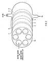
- Fig. 1 is a configuration diagram showing a sectional construction of an apparatus for producing hydrogen according to an embodiment of the invention
- Fig. 2 is a general view thereof.
- the apparatus for producing hydrogen 10 has a structure where a proton conductor 3 is located between an anode 1 and a cathode 2 which are placed in the opposite direction, and water is electrolyzed at the anode 1 to generate protons (H + ), the generated protons (H + ) are conducted to the cathode 2 through the proton conductor 3, and hydrogen is generated from the protons (H + ) at the cathode 2, by supplying water in a gaseous state or a vapor state from a surface of the anode 1 being on the far side from the proton conductor 3 in a state of voltage applied between the anode 1 and the cathode 2.
- both electrodes 1 and 2 and the proton conductor 3 are placed to be integrated or contact, and have a shape of a flexible sheet but have sufficient strength from a viewpoint of handling or enlargement thereof.
- the anode 1 and the cathode 2 among these elements are preferably an active electrode with sufficiently low hydrogen generating potential. Moreover, they have preferably plasticity and a surface area enough to contact the proton conductor 3, as well as heat resisting properties, and for example, they are made of an electrode material such as porous or a mesh shape.
- At least either of the anode 1 or the cathode 2 and the proton conductor 3 are preferably located to sandwich a catalyst layer, and here, both electrodes 1 and 2, and the proton conductor 3 are respectively located to sandwich the catalyst layers 4.
- the electrodes 1 and 2 and the catalyst layers 4 are formed by preparing a sheet-like carbon fiber, porous carbon, or the like and applying an active catalyst to an surface thereof to be contacted to the proton conductor 3.
- the catalyst layers 4 for example, particles of platinum, ruthenium, or oxidation iridium are desirable, and other electrode substances such as silver may be preferable as long as the reaction at each of the above electrodes 1 and 2 is promoted.
- the formation of the catalyst layers 4 on one surface of each of the electrodes 1 and 2 can be performed by usual methods. For example, it may be performed by applying a catalyst or a precursor thereof to surfaces of carbon powder, processing the powder by the heating treatment or the like to form catalyst grains, and baking and applying the grains and a fluororesin over the surface of each of the electrodes 1 and 2.
- the catalyst layers 4, for example, made of an alloy of platinum and ruthenium may be respectively formed on the surfaces of electrodes 1 and 2 by applying the precursor of the catalyst, for example, a mixed aqueous solution of chloroplatinic acid and chlororuthenic acid, or a butyl alcohol solution over the surface of each of the electrodes 1 and 2, and then baking them in the reduction atmosphere containing hydrogen at a temperature of 200°C - 350°C.
- the precursor of the catalyst for example, a mixed aqueous solution of chloroplatinic acid and chlororuthenic acid, or a butyl alcohol solution
- a metal net member made by knitting metal lines may be inserted into or applied on the sheet-like electrodes 1 and 2 as a core material.
- the conductivity of the electrodes themselves is improved and a uniform current distribution can be expected over the whole surfaces.
- the proton conductor 3 is a conduction medium of protons (H + ) and has a structure containing a derivative where an essential part is at least one kind selected from the group consisting of fullerenes, carbon clusters, and linear carbon structures and a proton (H + ) dissociating group is introduced into carbon atom thereof.
- fullerene which serves as an essential part of the derivative is not especially be limited to a spherical-shell-like cluster
- a simple substance fullerene selected from C 36 , C 60 , C 70 , C 76 , C 78 , C 80 , C 82 , C 84 , or a mixture of two or more kinds among these is preferably used in general.
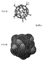
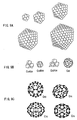
- Figs. 4A and 4B show a structure of fullerenol given by the introduction of multiple hydroxyl groups (OH groups) into the fullerene.
- OH groups hydroxyl groups
- the fullerene derivatives which can exhibit the proton conductivity with the same mechanism can include fullerene derivatives which OSO 3 H groups instead of the OH groups are introduced into: polyhydroxyl fullerenes, i.e., sulfuric ester fullerenols as shown in Fig. 5B, which has been reported also by Chiang et al. in 1994 (Chiang. L. Y.; Wang, L. Y.; Swirczewski, J. W.; Soled, S.; Cameron, S., and J. Org. Chem. 1994, 59, 3960).
- the sulfuric ester fullerenols include those only containing OSO 3 H groups and those containing both OSO 3 H and OH groups, in one molecule.
- any fullerene derivatives which can represent the proton conductivity may be composition materials of the proton conductor 3, and the introduced groups are not especially limited only to OH group and OSO 3 H group.
- the dissociating groups introduced into the fullerene are expressed as -XH, and X may express any atom or atomic group which has divalent valence number. Furthermore, the groups are expressed as -OH or -YOH, and Y may express any atom or atomic group which has divalent valence number.
- -COOH, -SO 3 H, or -OPO(OH) 2 is preferable in addition to -OH and OSO 3 H described above.
- fullerene derivatives represented by these fullerenols and the sulfuric ester fullerenols quite many functional groups such as OH groups and OSO 3 H groups can be introduced into one molecular of the fullerene which is the essential part, so significantly hydrogen ion density per unit volume increases, and efficient conductivity is represented, when large quantity thereof are aggregated.
- the good proton conductivity can be kept continuously, even if it is in the low humidity atmosphere, because the hydrogen ions (H + ) derived from the OH groups, the OSO 3 H groups, and the like directly concern with the proton conduction.
- the fullerene itself has electrophilicity, so it is thought that ionization of the hydrogen ions is promoted also not only in the OSO 3 H groups with high acidity but in OH groups of the derivatives thereof, and that the proton conductivity is still higher.
- fullerene derivatives weigh light, are less subject to deteriorate, and contain no pollutant, since the most of them constituted of carbon atoms of the fullerene.
- the manufacturing costs of the fullerenes are also being reduced rapidly. Therefore, it can be said that the fullerenes not only have excellent material properties, but also are ideal electrolyte materials which are superior to any other materials even from the viewpoint of resources, economy, and the environment.
- fullerene derivatives which can be used for the embodiment are synthesized by treating the powder of the fullerene using an appropriate combination of the well-known processing such as the acid treatment and hydrolysis to introduce desired functional groups into the carbon atoms of the fullerene. Furthermore, the proton conductor 3 is obtained by forming the fullerene derivative into a film shape by the coating or the deposition. Here, the proton conductor 3 contacts to both sides of a porous separator 5.
- the proton conductor 3 may be formed into a film shape by pressing only the fullerene derivative.
- it may be formed into a film by adding a binder to the fullerene derivative and performing the pressing, the extrusion molding, or the like.
- Polymeric materials which can be used as the binder are not limited to those which produce as less inhibition of the conductivity of the protons (due to the reaction with the fullerene derivative) as possible, and which have workability for forming films. Usually, those which have no electron conductivity and good stability are used, and for example, one or two kinds or more of well-known polymers which have the workability for forming films are used.
- the concrete examples include polytetrafluoroethylene, polyvinylidene fluoride, polyvinyl alcohol, and these are more preferable polymeric materials for the reason explained below.
- polytetrafluoroethylene is preferable, because less mixing amount thereof enables larger thin films with higher strength to be easily formed compared with other polymeric materials.
- the mixing amount can become low, for example, it is 3 weight % or less, preferably 0.5 - 1.5 weight %, and thickness of the thin films can usually be reduced and become in a range from 100 ⁇ m to 1 ⁇ m.
- polyvinylidene fluoride and polyvinyl alcohol are preferable, because thin films which have the proton conductivity and the excellent ability of preventing gas permeability can be obtained.
- the mixing amount in this case is preferably in a range of 5-15 weight %.
- the proton conductor 3 into which the binder is added can not only exhibit the similar proton conductivity to the case of using only the fullerene derivative, but also has a thinner (about 300 ⁇ m or less) and more flexible structure with higher strength and the ability of preventing the gas permeability, compared with the compression-molded objects of the fullerene derivative powder.
- carbon clusters are aggregates formed by bonding or aggregating several to hundreds of atoms, and the aggregating (assembling) thereof can improve the performance of the proton conductivity. Bonds between the atoms can provide films of the carbon clusters with high strength and enable layers to be formed easily.
- the clusters contain carbon as a principal component, and are the aggregates formed by bonding several to hundreds of carbon atoms by any kind of carbon-carbon bonds. It should be noticed that the composition thereof is not necessarily limited only to 100% carbon cluster, and may also be mixtures containing other atoms.
- aggregates which have a large number of carbon atoms also including such a case are called the carbon clusters.
- the carbon clusters are used as the essential part, because a lot of proton dissociating groups are needed to be introduced for providing the excellent proton conductivity, and can be accomplished by the carbon clusters.
- the acidity of the solid-like proton conductor becomes remarkably high, but the carbon clusters are less subject to oxidative deterioration unlike other carbon structures, and has excellent durability, and the constituent atoms bond each other closely, so the bonds between the atoms is not be broken even if the acidity is high (namely, it is hard to change chemically), and thus the film structure can be maintained.
- Figs. 9A to 12G show examples of the carbon clusters used as a raw material of the proton conductor 3 respectively.
- Figs. 9A to 9C represent carbon cluster groups which have sphere, prolate spheroid, or closed surface structure similar to these where many carbon atoms gather (in addition, molecule-like fullerenes are also shown).
- Figs. 10A to 10D represent carbon cluster groups which have a structure in which a part of spherical shell of the clusters shown in Figs. 9A to 10C 9C are missing (the black portions in Figs. 10C and 10D represent 5-membered ring or 7-membered ring). In these cases, the structure has an open edge, which is characteristic, and such structure can be found in many cases as a subproduct in manufacturing processes of the fullerenes using arc discharge.
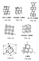
- Figs. 11A to 11G show carbon clusters having a diamond structure where most carbon atoms form SP 3 bonds.
- the clusters where most of the carbon atoms form SP 2 bonds have a planar structure of graphite, or the whole or a part of the structure of the fullerene or a nanotube.
- many clusters having the graphite structure have electron conductivity, and thus are not preferable as the essential part of the proton conductor.
- the SP 2 bonds of the fullerene and the nanotube partially contains elements of SP 3 bond, and thus many of them have no electron conductivity, and they are preferable as the essential part of the proton conductor 3.
- Figs. 12A to 12G show the cases of clusters bonding each other (the thin lines drawn between the clusters in Fig. 12A represent binding chains such as -(CH 2 ) n - and -(CF 2 ) n -, and the black portions in Figs. 12D to 12G represent 5-membered ring or 7-membered rings). Such a structure is also applicable.
- the carbon clusters as the essential part have a long axis of 100 nm or less, especially and preferably of 10 nm or less, and it is desirable to have two or more functional groups being introduced into the clusters.
- the carbon clusters are preferably basket-like structures or structures having at least partially an open edge.
- the fullerenes with the missing structure as the example have the reactivity of the fullerenes, and additionally and simultaneously, lacked sections thereof, i.e., open sections, have much higher reactivity. Therefore, by the acid treatment or the like, the introduction of the acid (proton) dissociating groups is promoted, a higher rate of functional group introduction is obtained, and high proton conductivity is acquired. Moreover, larger-scale synthesis thereof becomes possible compared with the fullerenes, and the very inexpensive production is possible.
- the following manufacturing method is preferable.
- the carbon clusters made of carbon powder are produced using the arc discharge of a carbon electrode. Then, the carbon clusters are suitably treated by required steps selected from an acid treatment using sulfuric acid or the like, the hydrolysis or the like, and the sulfonation or phosphate esterification. Thereby, desired carbon cluster derivatives can be obtained easily.
- the carbon cluster derivatives can directly be formed into a shape such as films, pellets, or the like without a binder by the pressing.
- the proton conductor 3 containing such carbon cluster derivative as the principal component has the carbon cluster as the essential part, so the protons tend to be dissociated even in a dry environment, and the excellent effects including the proton conductivity are exhibited like the case where the fullerenes are used as the essential part. Moreover, as illustrated, there is an advantage of the broad range of choice for the material of the essential part.
- the linear carbon structures are preferably tube shapes or fiber shapes, and for example, a carbon nanotube or a carbon fiber is preferable.
- the carbon nanotube or the carbon fiber tends to emit electrons because of its structure, and can have very large surface area, which can accomplish more improvements in proton propagation efficiency.
- These can be manufactured by the arc discharge method or the chemical vapor deposition (the thermal CVD).
- the carbon nanotubes can be obtained using synthesis in the helium atmosphere (for example, at 20 kPa) with an arc discharge chamber and metal catalysts such as FeS, Ni, or Co, and deposition on an inner wall of the chamber into a cloth-like shape with the arc discharge.
- metal catalysts such as FeS, Ni, or Co
- the above carbon nanotube with a small bore can be obtained, when the above catalyst exists together, and the above carbon nanotube constituted of a multilayer with a large bore can be obtained, when the arc discharge is performed on the condition of non-catalyst.
- the proton dissociating groups can be introduced into the carbon nanotube obtained by the arc discharge method in a processing way similar to that of the above carbon clusters, and the proton conductor 3 which has excellent proton conductivity also in the dry environment is obtained.
- the chemical vapor deposition is the technique used for synthesizing the carbon nanotube or the carbon fiber by reacting transition metal particles with a hydrocarbon such as acetylene, benzene, and ethylene, or CO. Specifically, a transition metal substrate or a coat substrate is reacted with the hydrocarbon or CO gas to deposit the carbon nanotube or the carbon fiber on the substrate.
- a hydrocarbon such as acetylene, benzene, and ethylene, or CO.
- the carbon fiber having a structure as shown in the perspective view of Fig. 13C can be synthesized by locating a Ni substrate in a alumina tube heated at 700°C, and reacting it with toluene/ H 2 gas (for example, 100 sccm).
- an aspect ratio of the carbon nanotube is preferably 1:1000-1:10, and an aspect ratio of the carbon fiber is preferably 1:5000-1:10.
- the bore of these linear carbon structures is preferably 0.001-0.5 ⁇ m, and a length thereof is preferably 1-5 ⁇ m.
- the proton conductor 3 has a structure containing at least one kind of the carbon materials mentioned above. Moreover, it preferably contacts at least to one side of the porous separator 5 such as polyethylene (PE), and more preferably contacts to both sides thereof like the embodiment. Thereby, other substances except for the protons which exists on the anode 1 side, water, oxygen generated at the anodes 1 and the like, are prevented from transferring to the cathode 2 side, and simultaneously the form of the proton conductor 3 is maintained. In addition, holes of the porous separator 5 can be filled with the proton conductor 3, which enables the protons generated at the anode 1 to be conducted to the cathode 2 efficiently.
- PE polyethylene
- the proton conductor 3 is inserted between the anode 1 and the cathode 2 through the catalyst layers 4, and a main part section which is constituted so that each of the above layers might contact each other, is housed inside an outer frame 7A made of SUS or the like.
- a hole for supplying water vapor or the water vapor-containing air is located in the outer frame 7A on the anode 1 side.
- a H 2 storage tank 6 for holding or storing the generated hydrogen is located on the cathode 2 side of the main part section.
- the H 2 storage tank 6 has a N 2 feed opening 8 for supplying nitrogen (N 2 ) which is an inert gas, and a N 2 outlet 9 for extracting hydrogen stored inside with discharging nitrogen (N 2 ).
- the H 2 storage tank 6 can be composed of glass, metals, plastics, or the like, or can be also a cartridge-type one which is exchangeable when being filling with hydrogen.
- a hydrogen occluding alloy may be attached to the inside so that hydrogen may be absorbed and stored in it.
- electric supply means for the electrodes 1 and 2 are not especially limited, it is preferable to use metals with heat resistance and corrosion resistance, for example, those constituted of a conductive oxide with stable conductivity such as ruthenium oxide coated on a titanium mesh surface can be used suitably.
- the temperature at the time of the water electrolysis is any temperature at which water exists as gas: preferably -50 to 300°C, and more preferably -40 to 160°C. The reason is that the temperature lower than the above range decreases the conductivity of the proton conductor 3, causing reduction of the efficiency, and the higher temperature easily causes decomposition of the proton conductor 3 itself.
- the partial pressure of water (vapor) supplied to the anode 1 is preferably 267 Pa - 267 kPa. The reasons are that the partial pressure lower than the above range can prevent sufficient decomposed hydrogen from be obtained, and the higher pressure can easily occur degradation of the cell properties due to dew condensation of water.
- hydrogen produced in such way is stored in the H 2 storage tank 6 which is directly attached on one side of the cathode 2.
- a fuel cell is combined to the N 2 storage tank 6 through a bulb such as the N 2 outlet 9, hydrogen can be supplied to the fuel cell.
- absorbed hydrogen can be emitted by heating the hydrogen occluding alloy.
- the apparatus for producing hydrogen 10 is used combining a solar battery or wind power, energy storage is enabled by transforming natural energy into electrical energy, and then transforming the transformed electrical energy into hydrogen by the apparatus for producing hydrogen 10.
- the proton conductor 3 which itself has the proton conductivity is used as a solid electrolyte layer between the anode 1 and the cathode 2, so hydrogen can be produced in the air of the low humidity state. Therefore, the operation is merely performed in the air without humidifying to high humidity unlike the conventional example using the Nafion, so an initial operation of the hydrogen manufacturing can start early, and no humidifier can be needed. Furthermore, it is not necessary to adjust temperature, humidity, pressure, and the like, so hydrogen can be produced simply and efficiently. It should be noticed that a humidifier may be mounted to humidify the proton conductor 3 in the apparatus for producing hydrogen.
- Fig. 8 is a view showing a relation between temperature and conductivity in the utilization of the fullerene derivatives such as the fullerenols as the proton conductor 3, comparing with the utilization of Nafion instead of the proton conductor 3.
- the results show that the utilization of Nafion prevented the exhibition of the ion conduction unless being in the humidified or flooded state, and an operational temperature range thereof is also narrow, but the utilization of the fullerene derivatives can provide the ion conductivity of 10-100 mS/cm higher than that of Nafion even in no humidification.
- the conventional hydrogen manufacturing has needed the dehumidifiers due to simultaneously generating water, because Nafion conducts the H 3 O + ions.
- only hydrogen can be produced and no dehumidifier can be needed, because the proton conductor 3 allows the protons (H + ) to be conducted and these are converted into hydrogen.
- the apparatus for producing hydrogen 10 can be a more compact and highly versatile apparatus, and hydrogen can be produced efficiently and simply by using the apparatus.
- the apparatus for producing hydrogen 10 can not only produce hydrogen, but also supply hydrogen to the fuel cells and the like, and conversely, transform electrical energy into hydrogen to store the energy.
- Fig. 3 is a sectional view showing the construction of an electrochemistry device according to the embodiment.
- the electrochemistry device 20 has main portions constructed in the same way as the apparatus for producing hydrogen 10, and has a structure which enables two kinds of operations of the step of generating hydrogen by electrolyzing water with the above electrode reaction like the apparatus for producing hydrogen 10, and the step of generating water from hydrogen with the reverse reaction thereof. Therefore, the same elements as the apparatus for producing hydrogen 10 will be denoted by the same symbols, and the description thereof will be eliminated accordingly.
- Oxygen is supplied from the oxygen feed opening 21 to a surface of the anode 1 on the outer frame 7 side.
- water generated at the anode 1 is discharged through the H 2 O outlet 22.
- the electrochemistry device 20 not only hydrogen is generated from water and stored in the H 2 storage tank 6 like the apparatus for producing hydrogen 10, but the generated and stored hydrogen is decomposed into protons (H + ) at the cathode 2, and the protons (H + ) are conducted to the anode 1 through the proton conductor 3, and the protons (H + ) are converted into water at the anode 1.
- the reactions of both electrodes in that case are: Anode 1:1/2O 2 +2H + +2e - -> H 2 O
- Cathode 2 H 2 -> 2H + +2e -
- electrochemistry energy is obtained between the cathode 2 and the anode 1. That is, the electrochemistry device 20 can be used as a fuel cell.
- oxygen generated at the anode 1 in the hydrogen producing process it is also possible to store oxygen generated at the anode 1 in the hydrogen producing process, and oxygen can also be recycled by supplying the stored oxygen to the anode 1 in the electrochemistry energy generating process.
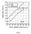
- Fig. 6 is a view showing a relation between partial pressure of the supplied water and current density obtained as output of the device 20 in the utilization of sulfuric ester fullerenol as the proton conductor 3 of the electrochemistry device 20 comparing with the utilization of Nafion instead of the proton conductor 3.
- electric current output can be favorably obtained when the electrochemistry device 20 using the fullerene derivative is used, but the current density is almost 0 mA/cm 2 when Nafion is used.
- the amount of electric current is proportional to the partial pressure of water, and also the higher the operating temperature, the higher the electric current obtained, in the electrochemistry device 20.
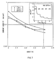
- Fig. 7 shows a relation between temperature and current density in the utilization of the fullerene derivative as the proton conductor 3.
- the Figure indicates that the higher the setting temperature of the apparatus and the higher the partial pressure of water, the higher the current density obtained.
- the electrochemistry device 20 has the same composition as the apparatus for producing hydrogen 10, and thus the same effect as the apparatus for producing hydrogen 10 can be demonstrated, and the efficient operations can be possible.
- the proton conductor 3 was produced by applying a mixture prepared by mixing fullerenol (C 60 (OH) n ) powder and THF (tetrahydrofuran) liquid with 1:2 weight ratio to both sides of a porous polyethylene film (30% of a porosity rate) 5 having a film thickness of 9 ⁇ m by the doctor blade method, and drying in the room temperature and the room air for 15 minutes.
- the anode 1 and the cathode 2 were produced by supporting Pt on each surface not to contact to the proton conductor 3 of carbon sheets as the anode 1 and the cathode 2 in order to enlarge an area in contact with the proton conductor 3, applying the above obtained mixture of the fullerenol and THF also to the Pt support surfaces of the carbon sheets, and drying on the same conditions as those of producing the proton conductor 3.
- the cathode 2 and the anode 1 to which the fullerenol was applied were pasted to both sides of the above obtained proton conductor 3 so that the catalyst support surfaces might contact to the proton conductor 3, and the shape thereof was formed by the pressing.
- the pressure was 500 kg/cm 2 .
- an MEA film of 500 ⁇ m in apparent thickness was formed.
- a measuring tub was prepared by fixing a SUS board spacing 2 mm away from a surface of the cathode 2 and sealing the periphery to provide a space adjacent to the cathode 2, and fixing the MEA film so that the cathode 2 for generating hydrogen might direct inside and the anode 1 in contact with the air might direct outside.
- a nitrogen feed opening 8 and an outlet 9 were located in the measuring tub, and 20 sccm of dry nitrogen gas was circulated.
- a hydrogen concentration analyzer for measuring hydrogen in the nitrogen is attached to the outlet 9.
- the measuring tub was put into a constant temperature and humidity chamber, water was electrolyzed in the vapor state or the gas state sending the air to the anode 1 side.
- the hydrogen concentration before applying voltage was zero, i.e., below the measurement limit.
- the temperature of the constant temperature and humidity chamber was set to 25°C
- the humidity was set to 20% by using a drying agent or the like
- the electrolytic voltage was increased from 0 V to 1.5 V at the rate of 1 mV/sec
- the state of applying 1.5 V was hold for 10 minutes
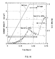
- the humidity was increased from 20% to 60%. Consequently, significant increase in current density as shown in Fig. 14 was found.
- the reason is that H 2 O in the air was decomposed into oxygen and protons on the surface of the anode catalyst layer of the MEA film and the protons were transferred to the cathode side.
- the constant temperature and humidity chamber of the apparatus for producing hydrogen made of the MEA film produced in Example 1 was set to 25°C and 60% of humidity, the electrolytic voltage was increased from 0 V to 1.5 V at the rate of 1 mV/sec, and the state of applying 1.5 V was hold, and 10 minutes later, the formation of about 1000 ppm of H 2 was found in the nitrogen gas in the measuring tub. Moreover, very slight entry of O 2 was found in the generated hydrogen. It is thought that the separation from the atmosphere by the sealing seal or the fullerenol as the proton conduction film was inadequate. In addition, each of O 2 and H 2 O was 1 ppm or less in the hydrogen generated at the cathode 2 side, and the obtained purity was as the same level as that of hydrogen acquired in the usual water electrolysis.
- the constant temperature and humidity chamber of the apparatus for producing hydrogen made of the MEA film produced in Example 1 was set to 25°C and 90% of humidity, the electrolytic voltage was increased from 0 V to 1.5 V at the rate of 1 mV/sec, and the state of applying 1.5 V was hold, and 10 minutes later, the formation of about 10000 ppm of H 2 was found in the nitrogen gas in the measuring tub. Moreover, very slight entry of O 2 was found in the generated hydrogen. It is thought that the separation from the atmosphere by the sealing seal or the fullerenol as the proton conduction film was inadequate. In addition, each of O 2 and H 2 O was 1 ppm or less in the hydrogen generated at the cathode 2 side, and the obtained purity was as the same level as that of hydrogen acquired in the usual water electrolysis.
- Example 2 The similar experiments were performed on the conditions of the constant temperature and humidity chamber of Example 2, using Nafion 415 manufactured by DuPont, instead of the proton conductor 3 where the porous film (separator) 6 supported the fullerenol.
- the electrolytic voltage was increased from 0 V to 1.5V at the rate of 1 mV/sec and the state of applying 1.5 V was hold, the current density was 0.01 mA/cm 2 or less, and the hydrogen concentration in the nitrogen gas in the measuring tub was 1 ppm (the measurement limit) or less.
- the hydrogen produce experiment was performed for 2 hours on the condition of Comparative Example 2 using the Nafion film, and finally the generated hydrogen concentration was decreased to about 50 ppm.
- the reason given is that H 2 O generated at the cathode 2 side was deposited on the electrode surface.
- the nitrogen feed opening 8 and the outlet 9 of the measuring tub were sealed, the constant temperature and humidity chamber was set to 25°C and 60% of humidity, 0-1.6 V of the voltage was applied to the cell using the fullerenol as the proton conductor in a constant current mode of 1 mA/cm 2 , the electrolysis was performed, and the generated hydrogen was stored. Consequently, hydrogen corresponding to 1.3 mAh/cm 2 of the electric current amount as shown in Fig. 15 was allowed to be generated and stored inside of the measuring tub.
- the measuring tub was sealed like Example 4, the constant temperature and humidity chamber was set to 25°C and 65% of humidity, 0-1.6 V of the voltage was applied to the cell using the fullerenol as the proton conductor in the constant current mode of 1 mA/cm 2 , the electrolysis was performed, and hydrogen corresponding to 1.3 mAh/cm 2 of the electric current amount was generated and stored inside of the measuring tub.
- the initial voltage in the utilization as fuel cell was 1.4 V, and, finally 1.2 mAh(s)/cell of the electric current amount was allowed to be obtained as shown in Fig. 15.
- the operation voltage is suitably 0.7 V for generating power in the cell at 10 mA/cm 2 .
- Devices requiring high voltage can operate by connecting the cell in series.
- the fullerene derivative such as the fullerenol was used as the proton conductor, so it was possible to efficiently produce hydrogen without humidifier or dehumidifier even in the air with the low humidity state, and to generate electric power using the generated hydrogen.
- the proton conductor which has a structure containing a carbon material which is at least one kind selected from the group consisting of the fullerenes, the carbon clusters, and the linear carbon structures where a proton (H + ) dissociating group is introduced into at least a part of carbon atoms, is located between the anode and the cathode, so the proton conductor functions even in the low humidity atmosphere, and thus no humidifier is required, and the early initial operation at the time of hydrogen producing is possible without taking long time to start the steady operation.
- the constitution thereof is like the apparatus for producing hydrogen of the invention, so operating in the low humidity atmosphere is possible. Therefore, neither humidifier nor dehumidifier is required, producing hydrogen and generating electrochemistry energy can be performed efficiently.
Abstract
The invention provides an apparatus for producing hydrogen and a
method for producing hydrogen which effectively produce hydrogen in the
low humidity atmosphere without humidifier or dehumidifier, and an
electrochemistry device and a method for generating electrochemistry energy
which generate electrochemistry energy by an oxidation-reduction reaction
using hydrogen. A fullerene derivative where a proton (H+) dissociating
group is introduced into a fullerene, is used as a composition material of a
proton conductor 3, water is supplied to an anode 1 in a vapor or gas state
and is electrolyzed, and produced protons (H+) are conducted to a cathode 2
through the proton conductor 3 and converted into hydrogen here.
Moreover, hydrogen produced in such a way is decomposed into protons (H+)
at the cathode 2, the protons are conducted to the anode 1 through the proton
conductor 3 and converted into water there, and then, electrochemistry
energy is extracted between the cathode 2 and the anode 1.
Description
The invention relates to an apparatus for producing hydrogen, an
electrochemistry device, a method for producing hydrogen, and a method for
generating electrochemistry energy.
Research of new energy is directed at solving energy problems in
recent years. Particularly, hydrogen energy has features such as an
inexhaustible supply, pollution-free, and high thermal efficiency, and many
researchers have investigated various leading candidates for future new
energy.
The methods of producing hydrogen are classified into two kinds.
One method is to decompose water to produce hydrogen and oxygen using
electric power, sunlight, nuclear heat, or the like, and the another method is
to extract hydrogen by the thermal reforming using a natural gas as a raw
material. There are problems of discharging carbon dioxide in the
producing process, using fossil fuel, and the like, in the latter method for
producing hydrogen, and the former method for producing hydrogen using
water electrolysis utilizing the electric power, the sunlight, the nuclear heat,
or the like, is indispensable to construction of a clean energy system.
Traditionally, producing hydrogen is performed by water electrolysis
using a low-temperature solid electrolyte film such as a perfluorosulfonic
acid resin. The perfluorosulfonic acid resin can include Nafion 117
(hereinafter is named simply as Nafion) from DuPont, for example.
Fig. 16 is a sectional view showing an outline of a conventional
apparatus of producing hydrogen. In the apparatus, Nafion 103 is located
between an anode 101 and a cathode 102 which are placed in the opposite
direction, and the following chemical reactions occur at the anode 101 and
the cathode 102 respectively.
Anode: 3H2O -> 2H3O++1/2O2+2e-
Cathode: 2H3O++2e- -> H2+2H2O
That is, water is electrolyzed at the anode 101 to give H3O+ ions, the
H3O+ ions are conducted from the anode 101 to the cathode 102 through the
Nafion 103, and hydrogen is generated from the H3O+ ions at the cathode
102.
There are the following problems in such apparatus for producing
hydrogen.
First, the Nafion 103 is an H3O+ ion conductor, and the conductivity
is not maintained in the low humidity atmosphere. Rather, it functions
under the existence of a lot of water. Then, it becomes indispensable to be
equipped with a humidifier on the side of the anode 101 where the H3O+ ions
are produced, so that the Nafion 103 may to fully include moisture.
Furthermore, it takes long time to start a steady operation, because
the initial stage of the electrolysis requires a supply of water vapor sufficient
to allow the Nafion 103 to function.
Moreover, the above method for producing hydrogen generates water
with hydrogen. For this reason, a dehumidifier is indispensable on the
cathode 102 side.
The present invention has been achieved to solve the above problems.
It is an object of the invention to provide an apparatus for producing
hydrogen and a method for producing hydrogen which effectively produce
hydrogen in the low humidity atmosphere with no humidifier nor
dehumidifier, and an electrochemistry device and a method for generating
electrochemistry energy which generates electrochemistry energy by an
oxidation-reduction reaction using hydrogen.
An apparatus for producing hydrogen of the invention comprises a
proton conductor which is located between an anode and a cathode and has a
structure containing a carbon material that is at least one kind selected from
the group consisting of fullerenes, carbon clusters, and linear carbon
structures where a proton (H+) dissociating group is introduced into at least
a part of carbon atoms.
Moreover, a method for producing hydrogen of the invention is to
supply water in a gaseous state or a vapor state from at least one surface of
an anode, electrolyze water at the anode to produce protons (H+), conduct the
protons (H+) from the anode to a cathode through a proton conductor, and
convert the protons (H+) into hydrogen at the cathode, using the apparatus
for producing hydrogen of the invention.
Furthermore, an electrochemistry device of the invention comprises a
proton conductor which is located between an anode and a cathode and has a
structure containing a carbon material that is at least one kind selected from
the group consisting of fullerenes, carbon clusters, and linear carbon
structure where a proton (H+) dissociating group is introduced into at least a
part of the carbon atoms.
Furthermore, a method for generating electrochemistry energy of the
invention comprises the steps of: supplying water in a gaseous state or a
vapor state from at least one surface of an anode, electrolyzing water at the
anode to produce protons (H+), conducting the protons (H+) from the anode to
a cathode through a proton conductor, and generating hydrogen from the
protons (H+) at the cathode; and decomposing hydrogen at the cathode to
produce protons (H+), conducting the protons (H+) from the cathode to the
anode through the proton conductor, and producing water from the protons
(H+) at the anode, using the apparatus for producing hydrogen of the
invention.
The "proton (H+) dissociating group" in the invention means a
functional group which can release a proton by ionization, and the " proton
(H+) dissociation" means that a proton separates from the group by the
ionization.
According to the apparatus for producing hydrogen and the method
for producing hydrogen of the invention, the proton conductor, which has a
carbon material that is at least one kind selected from the group consisting of
fullerenes, carbon clusters, and linear carbon structures where a proton (H+)
dissociating group is introduced into at least some of the carbon atoms, is
located between both poles as an electrolyte, and hydrogen (H2) is generated
from the protons (H+) which are conducted from the anode to the cathode
through the proton conductor functioning even in a low humidity
atmosphere.
According to the electrochemistry device and the method for
generating electrochemistry energy of the invention, the proton conductor,
which has a structure containing a carbon material that is at least one kind
selected from the group consisting of fullerenes, carbon clusters, and linear
carbon structures where a proton (H+) dissociating group is introduced into
at least some of the carbon atoms, is located between both poles as an
electrolyte, hydrogen (H2) is generated from the protons (H+) which are
conducted from the anode to the cathode through the proton conductor which
functioning even in a low humidity atmosphere, and water (H2O) is
generated from the protons (H+) which are conducted from the cathode to the
anode.
Other and further objects, features and advantages of the invention
will appear more fully from the following description.
The invention will be described below more in detail based on
embodiments.
Fig. 1 is a configuration diagram showing a sectional construction of
an apparatus for producing hydrogen according to an embodiment of the
invention, and Fig. 2 is a general view thereof. The apparatus for producing
hydrogen 10 has a structure where a proton conductor 3 is located between
an anode 1 and a cathode 2 which are placed in the opposite direction, and
water is electrolyzed at the anode 1 to generate protons (H+), the generated
protons (H+) are conducted to the cathode 2 through the proton conductor 3,
and hydrogen is generated from the protons (H+) at the cathode 2, by
supplying water in a gaseous state or a vapor state from a surface of the
anode 1 being on the far side from the proton conductor 3 in a state of voltage
applied between the anode 1 and the cathode 2.
These elements, that is, the anode 1, the proton conductor 3, and the
cathode 2, are multilayered in this order and formed into a MEA (Membrane
& Electroassembly). Thus, it is preferable that both electrodes 1 and 2 and
the proton conductor 3 are placed to be integrated or contact, and have a
shape of a flexible sheet but have sufficient strength from a viewpoint of
handling or enlargement thereof.
In order to obtain a low electrolytic voltage, the anode 1 and the
cathode 2 among these elements, are preferably an active electrode with
sufficiently low hydrogen generating potential. Moreover, they have
preferably plasticity and a surface area enough to contact the proton
conductor 3, as well as heat resisting properties, and for example, they are
made of an electrode material such as porous or a mesh shape.
Moreover, at least either of the anode 1 or the cathode 2 and the
proton conductor 3 are preferably located to sandwich a catalyst layer, and
here, both electrodes 1 and 2, and the proton conductor 3 are respectively
located to sandwich the catalyst layers 4. Thereby, the efficiency of water
electrolysis can be improved and the efficiency of hydrogen generation can be
improved more.
Specifically, the electrodes 1 and 2 and the catalyst layers 4 are
formed by preparing a sheet-like carbon fiber, porous carbon, or the like and
applying an active catalyst to an surface thereof to be contacted to the proton
conductor 3.
As a material of the catalyst layers 4, for example, particles of
platinum, ruthenium, or oxidation iridium are desirable, and other electrode
substances such as silver may be preferable as long as the reaction at each of
the above electrodes 1 and 2 is promoted.
The formation of the catalyst layers 4 on one surface of each of the
electrodes 1 and 2 can be performed by usual methods. For example, it may
be performed by applying a catalyst or a precursor thereof to surfaces of
carbon powder, processing the powder by the heating treatment or the like to
form catalyst grains, and baking and applying the grains and a fluororesin
over the surface of each of the electrodes 1 and 2. Alternatively, the catalyst
layers 4, for example, made of an alloy of platinum and ruthenium may be
respectively formed on the surfaces of electrodes 1 and 2 by applying the
precursor of the catalyst, for example, a mixed aqueous solution of
chloroplatinic acid and chlororuthenic acid, or a butyl alcohol solution over
the surface of each of the electrodes 1 and 2, and then baking them in the
reduction atmosphere containing hydrogen at a temperature of 200°C -
350°C.
Moreover, a metal net member made by knitting metal lines may be
inserted into or applied on the sheet- like electrodes 1 and 2 as a core
material. In this case, the conductivity of the electrodes themselves is
improved and a uniform current distribution can be expected over the whole
surfaces.
The proton conductor 3 is a conduction medium of protons (H+) and
has a structure containing a derivative where an essential part is at least
one kind selected from the group consisting of fullerenes, carbon clusters,
and linear carbon structures and a proton (H+) dissociating group is
introduced into carbon atom thereof.
First, the case of a proton conductor 3 with a structure containing a
fullerene derivative will be described.
Here, while the fullerene which serves as an essential part of the
derivative is not especially be limited to a spherical-shell-like cluster, a
simple substance fullerene selected from C36, C60, C70, C76, C78, C80, C82, C84,
or a mixture of two or more kinds among these is preferably used in general.
These fullerenes have been discovered in the mass analysis spectrum
of the cluster beam using the carbonaceous laser ablation in 1985 (Kroto,
H.W.; Heath, J.R.; O'Brien, S.C.;Curl, R.F.; Smalley, and R.E.Nature
1985.318,162.). It is five years later that the manufacture method thereof
was actually established, and the manufacturing method by the carbon
electrode arc discharge process was found out in 1990, and the fullerene has
attracted attention as a carbon semiconductor material or the like since
then.
Figs. 4A and 4B show a structure of fullerenol given by the
introduction of multiple hydroxyl groups (OH groups) into the fullerene. As
for the fullerenol, the example of the synthesis thereof was first reported by
Chiang et. al. in 1992 (Chiang, L. Y.; Swirczewski, J. W.; Hsu, C. S.;
Chowdhury, S. K.; Cameron, S.; Creegan, K., J. Chem. Soc, Chem. Commun.
1992, 1791).
The applicants has found for the first time that when the fullerenol is
shaped into an aggregation shown schematically in Fig. 5A (wherein circles
shown in the figures represent fullerene) and interacts with hydroxyl groups
which are mutually close to the fullerenol, the aggregation demonstrate high
proton conductivity (in other words, a H+ dissociating ability from a phenol
hydroxyl group) as a macroscopic aggregate.
The fullerene derivatives which can exhibit the proton conductivity
with the same mechanism can include fullerene derivatives which OSO3H
groups instead of the OH groups are introduced into: polyhydroxyl fullerenes,
i.e., sulfuric ester fullerenols as shown in Fig. 5B, which has been reported
also by Chiang et al. in 1994 (Chiang. L. Y.; Wang, L. Y.; Swirczewski, J. W.;
Soled, S.; Cameron, S., and J. Org. Chem. 1994, 59, 3960). The sulfuric
ester fullerenols include those only containing OSO3H groups and those
containing both OSO3H and OH groups, in one molecule.
It should be noticed that any fullerene derivatives which can
represent the proton conductivity, may be composition materials of the
proton conductor 3, and the introduced groups are not especially limited only
to OH group and OSO3H group.
That is, the dissociating groups introduced into the fullerene are
expressed as -XH, and X may express any atom or atomic group which has
divalent valence number. Furthermore, the groups are expressed as -OH or
-YOH, and Y may express any atom or atomic group which has divalent
valence number.
Specifically, -COOH, -SO3H, or -OPO(OH)2 is preferable in addition
to -OH and OSO3H described above.
In the fullerene derivatives represented by these fullerenols and the
sulfuric ester fullerenols, quite many functional groups such as OH groups
and OSO3H groups can be introduced into one molecular of the fullerene
which is the essential part, so significantly hydrogen ion density per unit
volume increases, and efficient conductivity is represented, when large
quantity thereof are aggregated.
Moreover, in these fullerenes derivatives, the good proton
conductivity can be kept continuously, even if it is in the low humidity
atmosphere, because the hydrogen ions (H+) derived from the OH groups, the
OSO3H groups, and the like directly concern with the proton conduction.
Furthermore, the fullerene itself has electrophilicity, so it is thought
that ionization of the hydrogen ions is promoted also not only in the OSO3H
groups with high acidity but in OH groups of the derivatives thereof, and
that the proton conductivity is still higher.
These fullerene derivatives weigh light, are less subject to
deteriorate, and contain no pollutant, since the most of them constituted of
carbon atoms of the fullerene. The manufacturing costs of the fullerenes
are also being reduced rapidly. Therefore, it can be said that the fullerenes
not only have excellent material properties, but also are ideal electrolyte
materials which are superior to any other materials even from the viewpoint
of resources, economy, and the environment.
These fullerene derivatives which can be used for the embodiment
are synthesized by treating the powder of the fullerene using an appropriate
combination of the well-known processing such as the acid treatment and
hydrolysis to introduce desired functional groups into the carbon atoms of
the fullerene. Furthermore, the proton conductor 3 is obtained by forming
the fullerene derivative into a film shape by the coating or the deposition.
Here, the proton conductor 3 contacts to both sides of a porous separator 5.
In addition, the proton conductor 3 may be formed into a film shape
by pressing only the fullerene derivative. Alternatively, it may be formed
into a film by adding a binder to the fullerene derivative and performing the
pressing, the extrusion molding, or the like.
Polymeric materials which can be used as the binder are not limited
to those which produce as less inhibition of the conductivity of the protons
(due to the reaction with the fullerene derivative) as possible, and which
have workability for forming films. Usually, those which have no electron
conductivity and good stability are used, and for example, one or two kinds or
more of well-known polymers which have the workability for forming films
are used. The concrete examples include polytetrafluoroethylene,
polyvinylidene fluoride, polyvinyl alcohol, and these are more preferable
polymeric materials for the reason explained below.
First, polytetrafluoroethylene is preferable, because less mixing
amount thereof enables larger thin films with higher strength to be easily
formed compared with other polymeric materials. In this case, the mixing
amount can become low, for example, it is 3 weight % or less, preferably 0.5 -
1.5 weight %, and thickness of the thin films can usually be reduced and
become in a range from 100 µm to 1 µm.
Moreover, polyvinylidene fluoride and polyvinyl alcohol are
preferable, because thin films which have the proton conductivity and the
excellent ability of preventing gas permeability can be obtained. The
mixing amount in this case is preferably in a range of 5-15 weight %.
Thus, the proton conductor 3 into which the binder is added, can not
only exhibit the similar proton conductivity to the case of using only the
fullerene derivative, but also has a thinner (about 300 µm or less) and more
flexible structure with higher strength and the ability of preventing the gas
permeability, compared with the compression-molded objects of the fullerene
derivative powder.
Next, the case of the proton conductor 3 with a structure containing a
derivative of a carbon cluster will be described.
Generally, carbon clusters are aggregates formed by bonding or
aggregating several to hundreds of atoms, and the aggregating (assembling)
thereof can improve the performance of the proton conductivity. Bonds
between the atoms can provide films of the carbon clusters with high
strength and enable layers to be formed easily. Moreover, the clusters
contain carbon as a principal component, and are the aggregates formed by
bonding several to hundreds of carbon atoms by any kind of carbon-carbon
bonds. It should be noticed that the composition thereof is not necessarily
limited only to 100% carbon cluster, and may also be mixtures containing
other atoms. Here, aggregates which have a large number of carbon atoms
also including such a case are called the carbon clusters.
The carbon clusters are used as the essential part, because a lot of
proton dissociating groups are needed to be introduced for providing the
excellent proton conductivity, and can be accomplished by the carbon clusters.
In such a case, the acidity of the solid-like proton conductor becomes
remarkably high, but the carbon clusters are less subject to oxidative
deterioration unlike other carbon structures, and has excellent durability,
and the constituent atoms bond each other closely, so the bonds between the
atoms is not be broken even if the acidity is high (namely, it is hard to change
chemically), and thus the film structure can be maintained.
Figs. 9A to 12G show examples of the carbon clusters used as a raw
material of the proton conductor 3 respectively. Figs. 9A to 9C represent
carbon cluster groups which have sphere, prolate spheroid, or closed surface
structure similar to these where many carbon atoms gather (in addition,
molecule-like fullerenes are also shown). On the other hand, Figs. 10A to
10D represent carbon cluster groups which have a structure in which a part
of spherical shell of the clusters shown in Figs. 9A to 10C 9C are missing (the
black portions in Figs. 10C and 10D represent 5-membered ring or
7-membered ring). In these cases, the structure has an open edge, which is
characteristic, and such structure can be found in many cases as a
subproduct in manufacturing processes of the fullerenes using arc discharge.
Moreover, Figs. 11A to 11G show carbon clusters having a diamond
structure where most carbon atoms form SP3 bonds.
It should be noticed that the clusters where most of the carbon atoms
form SP2 bonds, have a planar structure of graphite, or the whole or a part of
the structure of the fullerene or a nanotube. Among them, many clusters
having the graphite structure have electron conductivity, and thus are not
preferable as the essential part of the proton conductor.
On the contrary, the SP2 bonds of the fullerene and the nanotube
partially contains elements of SP3 bond, and thus many of them have no
electron conductivity, and they are preferable as the essential part of the
proton conductor 3.
Figs. 12A to 12G show the cases of clusters bonding each other (the
thin lines drawn between the clusters in Fig. 12A represent binding chains
such as -(CH2)n- and -(CF2)n-, and the black portions in Figs. 12D to 12G
represent 5-membered ring or 7-membered rings). Such a structure is also
applicable.
Here, the carbon clusters as the essential part have a long axis of 100
nm or less, especially and preferably of 10 nm or less, and it is desirable to
have two or more functional groups being introduced into the clusters.
Furthermore, the carbon clusters are preferably basket-like
structures or structures having at least partially an open edge. The
fullerenes with the missing structure as the example have the reactivity of
the fullerenes, and additionally and simultaneously, lacked sections thereof,
i.e., open sections, have much higher reactivity. Therefore, by the acid
treatment or the like, the introduction of the acid (proton) dissociating
groups is promoted, a higher rate of functional group introduction is
obtained, and high proton conductivity is acquired. Moreover, larger-scale
synthesis thereof becomes possible compared with the fullerenes, and the
very inexpensive production is possible.
As a means for introducing the proton dissociating groups described
previously into the above carbon clusters, the following manufacturing
method is preferable.
That is, first, the carbon clusters made of carbon powder are
produced using the arc discharge of a carbon electrode. Then, the carbon
clusters are suitably treated by required steps selected from an acid
treatment using sulfuric acid or the like, the hydrolysis or the like, and the
sulfonation or phosphate esterification. Thereby, desired carbon cluster
derivatives can be obtained easily. The carbon cluster derivatives can
directly be formed into a shape such as films, pellets, or the like without a
binder by the pressing.
The proton conductor 3 containing such carbon cluster derivative as
the principal component has the carbon cluster as the essential part, so the
protons tend to be dissociated even in a dry environment, and the excellent
effects including the proton conductivity are exhibited like the case where
the fullerenes are used as the essential part. Moreover, as illustrated, there
is an advantage of the broad range of choice for the material of the essential
part.
Next, the case of the proton conductor 3 with a structure containing a
derivative of the linear carbon structures will be described.
The linear carbon structures are preferably tube shapes or fiber
shapes, and for example, a carbon nanotube or a carbon fiber is preferable.
The carbon nanotube or the carbon fiber tends to emit electrons
because of its structure, and can have very large surface area, which can
accomplish more improvements in proton propagation efficiency.
These can be manufactured by the arc discharge method or the
chemical vapor deposition (the thermal CVD).
For example, with the arc discharge method, the carbon nanotubes
can be obtained using synthesis in the helium atmosphere (for example, at
20 kPa) with an arc discharge chamber and metal catalysts such as FeS, Ni,
or Co, and deposition on an inner wall of the chamber into a cloth-like shape
with the arc discharge. Here, the above carbon nanotube with a small bore
can be obtained, when the above catalyst exists together, and the above
carbon nanotube constituted of a multilayer with a large bore can be
obtained, when the arc discharge is performed on the condition of
non-catalyst.
A cylinder-like structure of a graphene sheet of the multilayer carbon
nanotube as shown in Figs. 13A and 13B, which can be produced using the
arc discharge on the condition of non-catalyst as mentioned above, is a high
quality carbon nanotube with no defect, and it is known that this has very
high efficiency as electron emission material.
The proton dissociating groups can be introduced into the carbon
nanotube obtained by the arc discharge method in a processing way similar
to that of the above carbon clusters, and the proton conductor 3 which has
excellent proton conductivity also in the dry environment is obtained.
The chemical vapor deposition is the technique used for synthesizing
the carbon nanotube or the carbon fiber by reacting transition metal
particles with a hydrocarbon such as acetylene, benzene, and ethylene, or CO.
Specifically, a transition metal substrate or a coat substrate is reacted with
the hydrocarbon or CO gas to deposit the carbon nanotube or the carbon fiber
on the substrate.
For example, the carbon fiber having a structure as shown in the
perspective view of Fig. 13C can be synthesized by locating a Ni substrate in
a alumina tube heated at 700°C, and reacting it with toluene/ H2 gas (for
example, 100 sccm).
In addition, an aspect ratio of the carbon nanotube is preferably
1:1000-1:10, and an aspect ratio of the carbon fiber is preferably 1:5000-1:10.
Moreover, the bore of these linear carbon structures is preferably 0.001-0.5
µm, and a length thereof is preferably 1-5 µm.
According to the embodiment, the proton conductor 3 has a structure
containing at least one kind of the carbon materials mentioned above.
Moreover, it preferably contacts at least to one side of the porous separator 5
such as polyethylene (PE), and more preferably contacts to both sides thereof
like the embodiment. Thereby, other substances except for the protons
which exists on the anode 1 side, water, oxygen generated at the anodes 1
and the like, are prevented from transferring to the cathode 2 side, and
simultaneously the form of the proton conductor 3 is maintained. In
addition, holes of the porous separator 5 can be filled with the proton
conductor 3, which enables the protons generated at the anode 1 to be
conducted to the cathode 2 efficiently.
The proton conductor 3 is inserted between the anode 1 and the
cathode 2 through the catalyst layers 4, and a main part section which is
constituted so that each of the above layers might contact each other, is
housed inside an outer frame 7A made of SUS or the like. A hole for
supplying water vapor or the water vapor-containing air is located in the
outer frame 7A on the anode 1 side.
Moreover, a H2 storage tank 6 for holding or storing the generated
hydrogen is located on the cathode 2 side of the main part section. The H2
storage tank 6 has a N2 feed opening 8 for supplying nitrogen (N2) which is
an inert gas, and a N2 outlet 9 for extracting hydrogen stored inside with
discharging nitrogen (N2). In addition, the H2 storage tank 6 can be
composed of glass, metals, plastics, or the like, or can be also a cartridge-type
one which is exchangeable when being filling with hydrogen. Alternatively,
a hydrogen occluding alloy may be attached to the inside so that hydrogen
may be absorbed and stored in it.
In addition, while electric supply means for the electrodes 1 and 2 are
not especially limited, it is preferable to use metals with heat resistance and
corrosion resistance, for example, those constituted of a conductive oxide
with stable conductivity such as ruthenium oxide coated on a titanium mesh
surface can be used suitably.
The following electrode reaction occurs at the anode 1 and the
cathode 2 of the apparatus for producing hydrogen 10 as constituted in the
above way.
Anode 1: H2O -> 2H++1/2O2+2e-
Cathode 2: 2H++2e- -> H2
That is, when energized between the anode 1 and the cathode 2, and
supplying water to one side of the anode 1 in a gaseous state or a vapor state
through the hole of the outer frame 7A, water is electrolyzed at the anode 1,
and protons (H+) is generated. These protons (H+) are conducted from the
anode 1 to the cathode 2 through the proton conductor 3, and the protons
(H+) are converted to hydrogen at the cathode 2. In this connection,
theoretical electrolytic voltage in that case is 1.22 V. In fact, electrode
overvoltage, electric resistance, and the like are added to this value and the
electrolytic voltage becomes about from 1.5 V to 2 V.
In addition, the temperature at the time of the water electrolysis is
any temperature at which water exists as gas: preferably -50 to 300°C, and
more preferably -40 to 160°C. The reason is that the temperature lower
than the above range decreases the conductivity of the proton conductor 3,
causing reduction of the efficiency, and the higher temperature easily causes
decomposition of the proton conductor 3 itself.
Moreover, the partial pressure of water (vapor) supplied to the anode
1 is preferably 267 Pa - 267 kPa. The reasons are that the partial pressure
lower than the above range can prevent sufficient decomposed hydrogen
from be obtained, and the higher pressure can easily occur degradation of the
cell properties due to dew condensation of water.
Here, hydrogen produced in such way is stored in the H2 storage tank
6 which is directly attached on one side of the cathode 2. For example, if a
fuel cell is combined to the N2 storage tank 6 through a bulb such as the N2
outlet 9, hydrogen can be supplied to the fuel cell. When storing hydrogen
using the hydrogen occluding alloy, absorbed hydrogen can be emitted by
heating the hydrogen occluding alloy. In any methods, it is possible to use
the stored hydrogen as a raw material of fuel cells.
Moreover, if the apparatus for producing hydrogen 10 is used
combining a solar battery or wind power, energy storage is enabled by
transforming natural energy into electrical energy, and then transforming
the transformed electrical energy into hydrogen by the apparatus for
producing hydrogen 10.
Thus, in the embodiment, the proton conductor 3 which itself has the
proton conductivity is used as a solid electrolyte layer between the anode 1
and the cathode 2, so hydrogen can be produced in the air of the low
humidity state. Therefore, the operation is merely performed in the air
without humidifying to high humidity unlike the conventional example
using the Nafion, so an initial operation of the hydrogen manufacturing can
start early, and no humidifier can be needed. Furthermore, it is not
necessary to adjust temperature, humidity, pressure, and the like, so
hydrogen can be produced simply and efficiently. It should be noticed that a
humidifier may be mounted to humidify the proton conductor 3 in the
apparatus for producing hydrogen.
Fig. 8 is a view showing a relation between temperature and
conductivity in the utilization of the fullerene derivatives such as the
fullerenols as the proton conductor 3, comparing with the utilization of
Nafion instead of the proton conductor 3. The results show that the
utilization of Nafion prevented the exhibition of the ion conduction unless
being in the humidified or flooded state, and an operational temperature
range thereof is also narrow, but the utilization of the fullerene derivatives
can provide the ion conductivity of 10-100 mS/cm higher than that of Nafion
even in no humidification.
Moreover, the conventional hydrogen manufacturing has needed the
dehumidifiers due to simultaneously generating water, because Nafion
conducts the H3O+ ions. On the other hand, according to the embodiment,
only hydrogen can be produced and no dehumidifier can be needed, because
the proton conductor 3 allows the protons (H+) to be conducted and these are
converted into hydrogen.
As mentioned above, the apparatus for producing hydrogen 10 can be
a more compact and highly versatile apparatus, and hydrogen can be
produced efficiently and simply by using the apparatus.
Furthermore, according to the embodiment, the apparatus for
producing hydrogen 10 can not only produce hydrogen, but also supply
hydrogen to the fuel cells and the like, and conversely, transform electrical
energy into hydrogen to store the energy.
Fig. 3 is a sectional view showing the construction of an
electrochemistry device according to the embodiment. The electrochemistry
device 20 has main portions constructed in the same way as the apparatus
for producing hydrogen 10, and has a structure which enables two kinds of
operations of the step of generating hydrogen by electrolyzing water with the
above electrode reaction like the apparatus for producing hydrogen 10, and
the step of generating water from hydrogen with the reverse reaction thereof.
Therefore, the same elements as the apparatus for producing hydrogen 10
will be denoted by the same symbols, and the description thereof will be
eliminated accordingly.
In the electrochemistry device 20, for example, an outer frame 7 with
a structure where an outer frame 7B is applied on the outer frame 7A, is
mounted and an oxygen feed opening 21 and a H2O outlet 22 lead to the
outer frame 7. Oxygen is supplied from the oxygen feed opening 21 to a
surface of the anode 1 on the outer frame 7 side. Moreover, water generated
at the anode 1 is discharged through the H2O outlet 22.
In the electrochemistry device 20, not only hydrogen is generated
from water and stored in the H2 storage tank 6 like the apparatus for
producing hydrogen 10, but the generated and stored hydrogen is
decomposed into protons (H+) at the cathode 2, and the protons (H+) are
conducted to the anode 1 through the proton conductor 3, and the protons
(H+) are converted into water at the anode 1. The reactions of both
electrodes in that case are:
Anode 1:1/2O2+2H++2e- -> H2O
Cathode 2: H2 -> 2H++2e-
In the reaction process, electrochemistry energy is obtained between the
cathode 2 and the anode 1. That is, the electrochemistry device 20 can be
used as a fuel cell.
In addition, it is also possible to store oxygen generated at the anode
1 in the hydrogen producing process, and oxygen can also be recycled by
supplying the stored oxygen to the anode 1 in the electrochemistry energy
generating process.
Fig. 6 is a view showing a relation between partial pressure of the
supplied water and current density obtained as output of the device 20 in the
utilization of sulfuric ester fullerenol as the proton conductor 3 of the
electrochemistry device 20 comparing with the utilization of Nafion instead
of the proton conductor 3. In the low humidity atmosphere with partial
pressure of water below 5 kPa (40 Torr), electric current output can be
favorably obtained when the electrochemistry device 20 using the fullerene
derivative is used, but the current density is almost 0 mA/cm2 when Nafion
is used. In addition, it is revealed that the amount of electric current is
proportional to the partial pressure of water, and also the higher the
operating temperature, the higher the electric current obtained, in the
electrochemistry device 20.
Furthermore, Fig. 7 shows a relation between temperature and
current density in the utilization of the fullerene derivative as the proton
conductor 3. The Figure indicates that the higher the setting temperature
of the apparatus and the higher the partial pressure of water, the higher the
current density obtained.
As described above, the electrochemistry device 20 has the same
composition as the apparatus for producing hydrogen 10, and thus the same
effect as the apparatus for producing hydrogen 10 can be demonstrated, and
the efficient operations can be possible.
Hereinafter, the invention will be described concretely based on
Examples.
An apparatus for producing hydrogen as shown in Fig. 1 was
fabricated. First, the proton conductor 3 was produced by applying a
mixture prepared by mixing fullerenol (C60(OH)n) powder and THF
(tetrahydrofuran) liquid with 1:2 weight ratio to both sides of a porous
polyethylene film (30% of a porosity rate) 5 having a film thickness of 9 µm
by the doctor blade method, and drying in the room temperature and the
room air for 15 minutes.
Then, the anode 1 and the cathode 2 were produced by supporting Pt
on each surface not to contact to the proton conductor 3 of carbon sheets as
the anode 1 and the cathode 2 in order to enlarge an area in contact with the
proton conductor 3, applying the above obtained mixture of the fullerenol
and THF also to the Pt support surfaces of the carbon sheets, and drying on
the same conditions as those of producing the proton conductor 3.
The cathode 2 and the anode 1 to which the fullerenol was applied,
were pasted to both sides of the above obtained proton conductor 3 so that
the catalyst support surfaces might contact to the proton conductor 3, and
the shape thereof was formed by the pressing. The pressure was 500 kg/cm2.
Thereby, an MEA film of 500 µm in apparent thickness was formed.
Next, in order to measure amounts of generated hydrogen, a
measuring tub was prepared by fixing a SUS board spacing 2 mm away from
a surface of the cathode 2 and sealing the periphery to provide a space
adjacent to the cathode 2, and fixing the MEA film so that the cathode 2 for
generating hydrogen might direct inside and the anode 1 in contact with the
air might direct outside. A nitrogen feed opening 8 and an outlet 9 were
located in the measuring tub, and 20 sccm of dry nitrogen gas was circulated.
A hydrogen concentration analyzer for measuring hydrogen in the nitrogen is
attached to the outlet 9. The measuring tub was put into a constant
temperature and humidity chamber, water was electrolyzed in the vapor
state or the gas state sending the air to the anode 1 side. The hydrogen
concentration before applying voltage was zero, i.e., below the measurement
limit.
Here, the temperature of the constant temperature and humidity
chamber was set to 25°C, the humidity was set to 20% by using a drying
agent or the like, the electrolytic voltage was increased from 0 V to 1.5 V at
the rate of 1 mV/sec, the state of applying 1.5 V was hold for 10 minutes, and
then, the humidity was increased from 20% to 60%. Consequently, significant
increase in current density as shown in Fig. 14 was found. The reason is
that H2O in the air was decomposed into oxygen and protons on the surface
of the anode catalyst layer of the MEA film and the protons were transferred
to the cathode side.
The constant temperature and humidity chamber of the apparatus
for producing hydrogen made of the MEA film produced in Example 1 was
set to 25°C and 60% of humidity, the electrolytic voltage was increased from
0 V to 1.5 V at the rate of 1 mV/sec, and the state of applying 1.5 V was hold,
and 10 minutes later, the formation of about 1000 ppm of H2 was found in the
nitrogen gas in the measuring tub. Moreover, very slight entry of O2 was
found in the generated hydrogen. It is thought that the separation from the
atmosphere by the sealing seal or the fullerenol as the proton conduction film
was inadequate. In addition, each of O2 and H2O was 1 ppm or less in the
hydrogen generated at the cathode 2 side, and the obtained purity was as the
same level as that of hydrogen acquired in the usual water electrolysis.
The constant temperature and humidity chamber of the apparatus
for producing hydrogen made of the MEA film produced in Example 1 was
set to 25°C and 90% of humidity, the electrolytic voltage was increased from
0 V to 1.5 V at the rate of 1 mV/sec, and the state of applying 1.5 V was hold,
and 10 minutes later, the formation of about 10000 ppm of H2 was found in
the nitrogen gas in the measuring tub. Moreover, very slight entry of O2
was found in the generated hydrogen. It is thought that the separation
from the atmosphere by the sealing seal or the fullerenol as the proton
conduction film was inadequate. In addition, each of O2 and H2O was 1 ppm
or less in the hydrogen generated at the cathode 2 side, and the obtained
purity was as the same level as that of hydrogen acquired in the usual water
electrolysis.
The similar experiments were performed on the conditions of the
constant temperature and humidity chamber of Example 2, using Nafion 415
manufactured by DuPont, instead of the proton conductor 3 where the
porous film (separator) 6 supported the fullerenol. When the electrolytic
voltage was increased from 0 V to 1.5V at the rate of 1 mV/sec and the state
of applying 1.5 V was hold, the current density was 0.01 mA/cm2 or less, and
the hydrogen concentration in the nitrogen gas in the measuring tub was 1
ppm (the measurement limit) or less.
The similar experiments were performed on the same conditions of
the constant temperature and humidity chamber of Example 3, using Nafion
415 manufactured by DuPont, instead of the proton conductor 3 where the
porous film (separator) 6 supported the fullerenol. When the electrolytic
voltage was increased from 0 V to 1.5V at the rate of 1 mV/sec and the state
of applying 1.5 V was hold, 10 minutes later, about 100 ppm of H2 was
formed in the nitrogen gas in the measuring tub, and 20 minutes later, about
1000 ppm of H2 was formed in the nitrogen gas in the measuring tub.
Moreover, at the same time of generating H2, the formation of about 2000
ppm of H2O was found in the nitrogen gas.
The hydrogen produce experiment was performed for 2 hours on the
condition of Comparative Example 2 using the Nafion film, and finally the
generated hydrogen concentration was decreased to about 50 ppm. The
reason given is that H2O generated at the cathode 2 side was deposited on
the electrode surface.
Obviously from Examples 1, 2, and 3 and Comparative Examples 1, 2,
and 3, the utilization of the Nafion film as the proton conductor did not allow
hydrogen to be generated, for example, in the atmosphere of 60% of humidity,
and allowed hydrogen to be generated but simultaneously water to be
generated in the atmosphere of 90% of humidity, so continuously producing
of hydrogen was not expected. On the other hand, in the method for
producing hydrogen and apparatus according to the invention, the fullerene
derivative such as the fullerenol, was used as the proton conductor, so it was
able to function even in the air with the low humidity state, and even
without humidifier or dehumidifier, it was possible to produce hydrogen
efficiently.
The nitrogen feed opening 8 and the outlet 9 of the measuring tub
were sealed, the constant temperature and humidity chamber was set to
25°C and 60% of humidity, 0-1.6 V of the voltage was applied to the cell using
the fullerenol as the proton conductor in a constant current mode of 1
mA/cm2, the electrolysis was performed, and the generated hydrogen was
stored. Consequently, hydrogen corresponding to 1.3 mAh/cm2 of the
electric current amount as shown in Fig. 15 was allowed to be generated and
stored inside of the measuring tub.
The measuring tub was sealed like Example 4, the constant
temperature and humidity chamber was set to 25°C and 65% of humidity,
0-1.6 V of the voltage was applied to the cell using the fullerenol as the
proton conductor in the constant current mode of 1 mA/cm2, the electrolysis
was performed, and hydrogen corresponding to 1.3 mAh/cm2 of the electric
current amount was generated and stored inside of the measuring tub.
When extracting the electric power using the stored hydrogen on the
condition of 10 mA/cm2 of the constant current mode, the initial voltage in
the utilization as fuel cell was 1.4 V, and, finally 1.2 mAh(s)/cell of the
electric current amount was allowed to be obtained as shown in Fig. 15.
Moreover, when extracting the electric current with 10 mA/cm2 of the current
density, the electromotive force began to be reduced due to the polarization
phenomenon, and was held approximately constant around 0.7 V. Therefore,
the operation voltage is suitably 0.7 V for generating power in the cell at 10
mA/cm2. Devices requiring high voltage can operate by connecting the cell
in series.
Obviously from Examples 4 and 5, in the method for producing
hydrogen and apparatus according to the invention, the fullerene derivative
such as the fullerenol was used as the proton conductor, so it was possible to
efficiently produce hydrogen without humidifier or dehumidifier even in the
air with the low humidity state, and to generate electric power using the
generated hydrogen.
Obviously from the mentioned above, according to the apparatus for
producing hydrogen and the method for producing hydrogen of the invention,
the proton conductor, which has a structure containing a carbon material
which is at least one kind selected from the group consisting of the fullerenes,
the carbon clusters, and the linear carbon structures where a proton (H+)
dissociating group is introduced into at least a part of carbon atoms, is
located between the anode and the cathode, so the proton conductor
functions even in the low humidity atmosphere, and thus no humidifier is
required, and the early initial operation at the time of hydrogen producing is
possible without taking long time to start the steady operation. Moreover,
only hydrogen (H2) is generated from the protons (H+) conducted from the
anode to the cathode through the proton conductor, so no dehumidifier is
required and only hydrogen can be obtained. Therefore, the apparatus
itself can become compact and produce hydrogen efficiently.
Moreover, according to the electrochemistry device and the method
for generating electrochemistry energy of the invention, the constitution
thereof is like the apparatus for producing hydrogen of the invention, so
operating in the low humidity atmosphere is possible. Therefore, neither
humidifier nor dehumidifier is required, producing hydrogen and generating
electrochemistry energy can be performed efficiently.
Obviously many modifications and variations of the present
invention are possible in the light of the above description. It is therefore to
be understood that within the scope of the appended claims the invention
may be practiced otherwise than as specifically described.
Claims (35)
- An apparatus for producing hydrogen comprising:an anode and a cathode which are placed in the opposite direction; anda proton conductor which is located between the anode and the cathode and has a structure containing a carbon material that is at least one kind selected from the group consisting of fullerenes, carbon clusters, and linear carbon structures where a proton (H+) dissociating group is introduced into at least a part of carbon atoms.
- An apparatus for producing hydrogen according to claim 1, wherein the anode has a surface on the far side from the cathode, which is placed in contact with water vapor or water vapor-containing air.
- An apparatus for producing hydrogen according to claim 1, wherein hydrogen generated at the cathode is held or stored with being sealed.
- An apparatus for producing hydrogen according to claim 1, wherein the cathode is porous or a mesh shape.
- An apparatus for producing hydrogen according to claim 1, wherein a catalyst layer is located between the proton conductor and at least either of the anode or the cathode.
- An apparatus for producing hydrogen according to claim 1, wherein a porous separator is located between the proton conductor and at least either of the anode or the cathode.
- An apparatus for producing hydrogen according to claim 1, wherein water in a vapor or gas state supplied to the anode has a partial pressure set within a range of 267 Pa - 267 kPa.
- An apparatus for producing hydrogen according to claim 1, wherein a temperature for electrolysis is set within a range of -50 to 300°C.
- An apparatus for producing hydrogen according to claim 1, wherein the proton dissociating group is -XH (X is any atom or atomic group which has divalent valence number and H is a hydrogen atoms).
- An apparatus for producing hydrogen according to claim 9, wherein the proton dissociating group is -OH or -YOH (Y is any atom or atomic group which has divalent valence number).
- An apparatus for producing hydrogen according to claim 10, wherein the proton dissociating group is selected from the group consisting of -OH, -OSO3H, -COOH, -SO3H, and -OPO(OH)2.
- An apparatus for producing hydrogen according to claim 1, wherein the fullerene is a spherical-shell-like carbon cluster Cm (m is natural number expressing carbon atom numbers to form the spherical-shell structure).
- An electrochemistry device using a reversible reaction of decomposition and generation of water and hydrogen comprising:an anode and a cathode which are placed in the opposite direction; anda proton conductor which is located between the anode and the cathode and has a structure containing a carbon material which is at least one kind selected from the group consisting of fullerenes, carbon clusters, and linear carbon structures where a proton (H+) dissociating group is introduced into at least a part of carbon atoms.
- An electrochemistry device according to claim 13, wherein the device is a fuel cell.
- An electrochemistry device according to claim 13, wherein the anode has a surface on the far side from the cathode, which is placed in contact with water vapor or water vapor-containing air.
- An electrochemistry device according to claim 13, wherein hydrogen generated at the cathode is held or stored with being sealed.
- An electrochemistry device according to claim 13, wherein the cathode is porous or mesh shape.
- An electrochemistry device according to claim 13, wherein a catalyst layer is located between the proton conductor and at least either of the anode or the cathode.
- An electrochemistry device according to claim 13, wherein a porous separator is located between the proton conductor and at least either of the anode or the cathode.
- An electrochemistry device according to claim 13, wherein water in a vapor or gas state supplied to the anode has a partial pressure set within a range of 267 Pa - 267 kPa.
- An electrochemistry device according to claim 13, wherein a temperature for electrolysis is set within a range of -50 to 300°C.
- An electrochemistry device according to claim 13, wherein the proton dissociating group is -XH (X is any atom or atomic group which has divalent valence number and H is a hydrogen atoms).
- An electrochemistry device according to claim 22, wherein the proton dissociating group is -OH or -YOH (Y is any atom or atomic group which has divalent valence number).
- An electrochemistry device according to claim 23, wherein the proton dissociating group is selected from the group consisting of -OH, -OSO3H, -COOH, -SO3H, and -OPO(OH)2.
- An electrochemistry device according to claim 13, wherein the fullerene is a spherical-shell-like carbon cluster Cm (m is natural number expressing carbon atom numbers to form the spherical-shell structure).
- A method for producing hydrogen using an apparatus for producing hydrogen comprising an anode and a cathode which are placed in the opposite direction, and a proton conductor which is located between the anode and the cathode has a structure containing a carbon material which is at least one kind selected from the group consisting of fullerenes, carbon clusters, and linear carbon structures where a proton (H+) dissociating group is introduced into at least a part of carbon atoms comprising the step of;
supplying water in a gaseous state or a vapor state from at least one surface of the anode, electrolyzing water at the anode to produce protons (H+), conducting the protons (H+) from the anode to the cathode through the proton conductor, and converting the protons (H+) to hydrogen at the cathode. - A method for producing hydrogen according to claim 26, wherein a surface of the anode on the far side from the cathode contacts water vapor or water vapor-containing air.
- A method for producing hydrogen according to claim 26, wherein hydrogen generated at the cathode is held or stored with being sealed.
- A method for producing hydrogen according to claim 26, wherein water is supplied to the anode in a vapor or gas state in 267 Pa - 267 kPa of partial pressure.
- A method for producing hydrogen according to claim 26, wherein the electrolyzing is performed in a temperature range of -50 to 300°C.
- A method for generating electrochemistry energy using an electrochemistry device comprising an anode and a cathode which are placed in the opposite direction, and a proton conductor which is located between the anode and the cathode has a structure containing a carbon material which is at least one kind selected from the group consisting of fullerenes, carbon clusters, and linear carbon structures where a proton (H+) dissociating group is introduced into at least a part of carbon atoms comprising the steps of:supplying water in a gaseous state or a vapor state from at least one surface of the anode, electrolyzing water at the anode to produce protons (H+), conducting the protons (H+) from the anode to the cathode through the proton conductor, and producing hydrogen from the protons (H+) at the cathode; anddecomposing hydrogen at the cathode to produce protons (H+), conducting the protons (H+) from the cathode to the anode through the proton conductor, and producing water from the protons (H+) at the anode.
- A method for generating electrochemistry energy according to claim 31, wherein a surface of the anode on the far side from the cathode contacts water vapor or water vapor-containing air.
- A method for generating electrochemistry energy according to claim 31, wherein hydrogen generated at the cathode is held or stored with being sealed.
- A method for generating electrochemistry energy according to claim 31, wherein water is supplied in a vapor or gas state in 267 Pa - 267 kPa of partial pressure.
- A method for generating electrochemistry energy according to claim 31, wherein the electrolyzing is performed in a temperature range of -50 to 300°C.
Applications Claiming Priority (3)
| Application Number | Priority Date | Filing Date | Title |
|---|---|---|---|
| JP2000386173 | 2000-12-20 | ||
| JP2000386173 | 2000-12-20 | ||
| PCT/JP2001/011196 WO2002050338A1 (en) | 2000-12-20 | 2001-12-20 | Apparatus for producing hydrogen, electrochemical device, method for producing hydrogen and method for generating electrochemical energy |
Publications (2)
| Publication Number | Publication Date |
|---|---|
| EP1344844A1 true EP1344844A1 (en) | 2003-09-17 |
| EP1344844A4 EP1344844A4 (en) | 2005-06-01 |
Family
ID=18853320
Family Applications (1)
| Application Number | Title | Priority Date | Filing Date |
|---|---|---|---|
| EP01994978A Withdrawn EP1344844A4 (en) | 2000-12-20 | 2001-12-20 | Apparatus for producing hydrogen, electrochemical device, method for producing hydrogen and method for generating electrochemical energy |
Country Status (6)
| Country | Link |
|---|---|
| US (1) | US7056423B2 (en) |
| EP (1) | EP1344844A4 (en) |
| JP (1) | JPWO2002050338A1 (en) |
| KR (1) | KR20020080429A (en) |
| CN (1) | CN1401016A (en) |
| WO (1) | WO2002050338A1 (en) |
Cited By (2)
| Publication number | Priority date | Publication date | Assignee | Title |
|---|---|---|---|---|
| EP1575102A1 (en) * | 2004-03-08 | 2005-09-14 | University&of&Basel | Electrical conductor based on proton conducting carbon nanotubes |
| GB2622072A (en) * | 2022-09-01 | 2024-03-06 | Oort Energy Ltd | A membrane electrode assembly |
Families Citing this family (14)
| Publication number | Priority date | Publication date | Assignee | Title |
|---|---|---|---|---|
| JP4887558B2 (en) * | 2000-11-07 | 2012-02-29 | ソニー株式会社 | How to use the fuel cell |
| JP4410127B2 (en) * | 2005-02-23 | 2010-02-03 | 三菱電機株式会社 | Electrochemical element and method for producing the same |
| JP2007319138A (en) * | 2006-06-05 | 2007-12-13 | Asahi Glass Green Tekku Kk | Construction material, building, and indoor environment adjustment method of building |
| US20100000876A1 (en) * | 2008-07-02 | 2010-01-07 | Sandbox Energy Systems, LLC | Caviation assisted sonochemical hydrogen production system |
| JP5375293B2 (en) * | 2009-04-09 | 2013-12-25 | トヨタ自動車株式会社 | Carbon nanotube manufacturing method and carbon nanotube manufacturing apparatus |
| RO126312A3 (en) * | 2010-07-23 | 2012-01-30 | Centrul De Cercetare Pentru Materiale Macromoleculare Şi Membrane S.A. | Electrocatalytic membrane system and process for obtaining fuel gas from water |
| CN102181878B (en) * | 2011-04-22 | 2013-11-13 | 北京航空航天大学 | Static water supply proton exchange membrane brine electrolysis device |
| US11094953B2 (en) * | 2015-05-26 | 2021-08-17 | 3M Innovative Properties Company | Electrode membrane assembly having an oxygen evolution catalyst electrodes, and methods of making and using the same |
| JP5846520B1 (en) | 2015-08-05 | 2016-01-20 | 株式会社センリョウ | Tank-type power generator and fuel cell vehicle capable of producing high-pressure hydrogen |
| ITUA20162598A1 (en) * | 2016-04-14 | 2017-10-14 | Ne M E Sys Srl | RECHARGEABLE ELECTROCHEMICAL DEVICE FOR THE PRODUCTION OF ELECTRICITY |
| US10337107B2 (en) * | 2016-05-03 | 2019-07-02 | University Of Louisville Research Foundation, Inc. | Solar hydrogen production from ambient water vapor electrolysis |
| CN105925999B (en) * | 2016-07-06 | 2018-06-15 | 扬州大学 | A kind of Fe2+Anodic oxidation and cathodic reduction co-production H2Process |
| CN106048641A (en) * | 2016-07-06 | 2016-10-26 | 扬州大学 | Process method of electrochemically preparing Fe3+ and H2 in pair |
| CN113802134A (en) * | 2021-08-20 | 2021-12-17 | 华南理工大学 | Hydrogen-enriched air preparation device for electrolyte membrane |
Citations (1)
| Publication number | Priority date | Publication date | Assignee | Title |
|---|---|---|---|---|
| EP1071149A2 (en) * | 1999-07-19 | 2001-01-24 | Sony Corporation | Proton conductor and method for manufacturing thereof, and fuel cell |
Family Cites Families (7)
| Publication number | Priority date | Publication date | Assignee | Title |
|---|---|---|---|---|
| JP3337235B2 (en) * | 1992-03-26 | 2002-10-21 | 出光興産株式会社 | Hydrogen storage |
| US5855748A (en) * | 1993-11-22 | 1999-01-05 | E. I. Du Pont De Nemours And Company | Electrochemical cell having a mass flow field made of glassy carbon |
| JP3807038B2 (en) * | 1997-07-10 | 2006-08-09 | 株式会社ジーエス・ユアサコーポレーション | POLYMER ELECTROLYTE MEMBRANE-GAS DIFFUSION ELECTRODE AND METHOD FOR PRODUCING THE SAME |
| US6299744B1 (en) * | 1997-09-10 | 2001-10-09 | California Institute Of Technology | Hydrogen generation by electrolysis of aqueous organic solutions |
| CN1169252C (en) * | 1997-11-25 | 2004-09-29 | 日本电池株式会社 | Solid high polymer electrolytic-catalytic composite electrode, electrode for fuel cell and manufacture thereof |
| JPH11217688A (en) | 1997-11-25 | 1999-08-10 | Japan Storage Battery Co Ltd | Solid polymer electrolyte-catalyst composite electrode, water electrolyzing device and fuel battery using the same |
| US6495290B1 (en) * | 1999-07-19 | 2002-12-17 | Sony Corporation | Proton conductor, production method thereof, and electrochemical device using the same |
-
2001
- 2001-12-20 KR KR1020027010769A patent/KR20020080429A/en not_active Application Discontinuation
- 2001-12-20 EP EP01994978A patent/EP1344844A4/en not_active Withdrawn
- 2001-12-20 CN CN01805090A patent/CN1401016A/en active Pending
- 2001-12-20 JP JP2002551210A patent/JPWO2002050338A1/en active Pending
- 2001-12-20 WO PCT/JP2001/011196 patent/WO2002050338A1/en not_active Application Discontinuation
- 2001-12-20 US US10/204,383 patent/US7056423B2/en not_active Expired - Fee Related
Patent Citations (1)
| Publication number | Priority date | Publication date | Assignee | Title |
|---|---|---|---|---|
| EP1071149A2 (en) * | 1999-07-19 | 2001-01-24 | Sony Corporation | Proton conductor and method for manufacturing thereof, and fuel cell |
Non-Patent Citations (1)
| Title |
|---|
| See also references of WO0250338A1 * |
Cited By (3)
| Publication number | Priority date | Publication date | Assignee | Title |
|---|---|---|---|---|
| EP1575102A1 (en) * | 2004-03-08 | 2005-09-14 | University&of&Basel | Electrical conductor based on proton conducting carbon nanotubes |
| WO2005091395A1 (en) * | 2004-03-08 | 2005-09-29 | University Of Basel | Electrical conductor based on proton conducting carbon nanotubes |
| GB2622072A (en) * | 2022-09-01 | 2024-03-06 | Oort Energy Ltd | A membrane electrode assembly |
Also Published As
| Publication number | Publication date |
|---|---|
| US7056423B2 (en) | 2006-06-06 |
| EP1344844A4 (en) | 2005-06-01 |
| JPWO2002050338A1 (en) | 2004-04-22 |
| WO2002050338A1 (en) | 2002-06-27 |
| CN1401016A (en) | 2003-03-05 |
| US20030116443A1 (en) | 2003-06-26 |
| KR20020080429A (en) | 2002-10-23 |
Similar Documents
| Publication | Publication Date | Title |
|---|---|---|
| JP3719178B2 (en) | Hydrogen gas production filling device and electrochemical device | |
| US6706431B2 (en) | Fuel cell | |
| Gülzow | Alkaline fuel cells: a critical view | |
| US7056423B2 (en) | Apparatus for producing hydrogen, electrochemical device, method for producing hydrogen and method for generating electrochemical energy | |
| JP4697378B2 (en) | Gas diffusing electrode, method for producing the same, conductive ionic conductor, and electrochemical device | |
| CN1166237A (en) | Fuel cell with solid polymer electrolytes | |
| JPWO2002027843A1 (en) | Fuel cell | |
| US7029782B2 (en) | Electrochemical hydrogen flow rate control system | |
| WO2002027844A1 (en) | Fuel cell and production method therefor | |
| KR20110001004A (en) | Catalyst for fuel cell and low-humidified mea | |
| JPWO2002027831A1 (en) | Fuel cell and method of manufacturing the same | |
| KR100908720B1 (en) | Membrane-electrode assembly for fuel cell, and fuel cell system comprising same | |
| KR20090062108A (en) | Membrane electrode assembly for proton exchange membrane fuel cell and manufacturing method of it | |
| KR101117630B1 (en) | Membrane-electrode assembly for fuel cell and method for preparating the same | |
| JP5115681B2 (en) | ELECTROLYTE MEMBRANE FOR FUEL CELL AND METHOD FOR PRODUCING ELECTROLYTE MEMBRANE FOR FUEL CELL | |
| WO2002027829A1 (en) | Method of producing fuel cell | |
| JP2002216776A (en) | Photo-electrochemical device | |
| JP2003280747A (en) | Gas pressure regulator, electrochemical device, gas storage device and gas pressure regulating method | |
| Ledjeff et al. | Development of pressure electrolyser and fuel cell with polymer electrolyte | |
| JP2001185162A (en) | Fuel cell and its manufacturing method | |
| WO2002056405A1 (en) | Power generating device | |
| Ivanova et al. | Investigation of the open bifunctional cathode for unitized reversible fuel cell: composition and performance | |
| CN116897449A (en) | Method for manufacturing catalyst layer for fuel cell | |
| Petrov et al. | Evaluation of polymer electrolyte fuel cell catalysts using gas diffusion electrodes in aqueous electrolytes | |
| Kimble et al. | Spiral-Wound PEM Fuel Cells for Portable Applications |
Legal Events
| Date | Code | Title | Description |
|---|---|---|---|
| PUAI | Public reference made under article 153(3) epc to a published international application that has entered the european phase |
Free format text: ORIGINAL CODE: 0009012 |
|
| 17P | Request for examination filed |
Effective date: 20021127 |
|
| AK | Designated contracting states |
Kind code of ref document: A1 Designated state(s): AT BE CH CY DE DK ES FI FR GB GR IE IT LI LU MC NL PT SE TR |
|
| RBV | Designated contracting states (corrected) |
Designated state(s): DE FR GB |
|
| A4 | Supplementary search report drawn up and despatched |
Effective date: 20050420 |
|
| STAA | Information on the status of an ep patent application or granted ep patent |
Free format text: STATUS: THE APPLICATION IS DEEMED TO BE WITHDRAWN |
|
| 18D | Application deemed to be withdrawn |
Effective date: 20060411 |