EP1347085B1 - Vortex spinning method and apparatus - Google Patents
Vortex spinning method and apparatus Download PDFInfo
- Publication number
- EP1347085B1 EP1347085B1 EP20030005279 EP03005279A EP1347085B1 EP 1347085 B1 EP1347085 B1 EP 1347085B1 EP 20030005279 EP20030005279 EP 20030005279 EP 03005279 A EP03005279 A EP 03005279A EP 1347085 B1 EP1347085 B1 EP 1347085B1
- Authority
- EP
- European Patent Office
- Prior art keywords
- spinning
- yarn
- fibers
- amount
- roller
- Prior art date
- Legal status (The legal status is an assumption and is not a legal conclusion. Google has not performed a legal analysis and makes no representation as to the accuracy of the status listed.)
- Expired - Lifetime
Links
- 238000000034 method Methods 0.000 title claims description 17
- 238000007382 vortex spinning Methods 0.000 title 1
- 238000009987 spinning Methods 0.000 claims description 233
- 239000000835 fiber Substances 0.000 claims description 105
- 238000007599 discharging Methods 0.000 claims description 59
- 238000004804 winding Methods 0.000 description 5
- 230000002950 deficient Effects 0.000 description 3
- 238000001514 detection method Methods 0.000 description 3
- 230000005540 biological transmission Effects 0.000 description 1
- 230000006835 compression Effects 0.000 description 1
- 238000007906 compression Methods 0.000 description 1
- 230000000694 effects Effects 0.000 description 1
- 230000002093 peripheral effect Effects 0.000 description 1
- 230000001360 synchronised effect Effects 0.000 description 1
- 238000011144 upstream manufacturing Methods 0.000 description 1
Images


Classifications
-
- D—TEXTILES; PAPER
- D01—NATURAL OR MAN-MADE THREADS OR FIBRES; SPINNING
- D01H—SPINNING OR TWISTING
- D01H4/00—Open-end spinning machines or arrangements for imparting twist to independently moving fibres separated from slivers; Piecing arrangements therefor; Covering endless core threads with fibres by open-end spinning techniques
- D01H4/02—Open-end spinning machines or arrangements for imparting twist to independently moving fibres separated from slivers; Piecing arrangements therefor; Covering endless core threads with fibres by open-end spinning techniques imparting twist by a fluid, e.g. air vortex
-
- D—TEXTILES; PAPER
- D01—NATURAL OR MAN-MADE THREADS OR FIBRES; SPINNING
- D01H—SPINNING OR TWISTING
- D01H1/00—Spinning or twisting machines in which the product is wound-up continuously
- D01H1/11—Spinning by false-twisting
- D01H1/115—Spinning by false-twisting using pneumatic means
-
- D—TEXTILES; PAPER
- D01—NATURAL OR MAN-MADE THREADS OR FIBRES; SPINNING
- D01H—SPINNING OR TWISTING
- D01H15/00—Piecing arrangements ; Automatic end-finding, e.g. by suction and reverse package rotation; Devices for temporarily storing yarn during piecing
- D01H15/002—Piecing arrangements ; Automatic end-finding, e.g. by suction and reverse package rotation; Devices for temporarily storing yarn during piecing for false-twisting spinning machines
Definitions
- the present invention relates to a spinning method and apparatus which manufactures a spun yarn by allowing a whirling air current to act on a bundle of fibers drafted by a draft device to twist the fibers.
- a conventional spinning method and apparatus is known (The Unexamined Japanese Patent Application Publication (Tokkai-Hei) No. 2001-40532). According to this method and apparatus, simply by supplying a bundle of fibers drafted by a draft device to a spinning member composed of a nozzle member generating a whirling air current, a hollow guide shaft, and the like without inserting a yarn called a "seed yarn” or a "leading yarn” through the spinning member, a yarn is generated and discharged (yarn discharging spinning, described later) using the nozzle member of the spinning member and an auxiliary nozzle formed in the hollow guide shaft. Subsequently, a yarn joining device joins together the yarn generated by the spinning member and a yarn connected to a winding package to allow spinning to be started or allow spinning to be resumed after yarn breakage.
- a spinning method of drafting supplied fibers at a predetermined total draft ratio and then spinning the fibers using a spinning member composed of a nozzle member having a nozzle hole first, before yarn discharging spinning, the amount of fibers supplied to the spinning member per unit time in a normal spinning state is changed to the amount of fibers supplied per unit time during the yarn discharging spinning, the latter amount being different from the former amount, and after the yarn discharging spinning has ended, the changed amount of fibers supplied is returned to the amount of fibers supplied in the normal spinning state.
- a yarn feeding device which exerts feeding force on a yarn spun out by the spinning member, and on the basis of a timing with which the yarn feeding device starts exerting yarn feeding force, the changed amount of fibers supplied is returned to the amount of fibers supplied in the normal spinning state.
- the amount of fibers supplied can be changed by changing, before the yarn discharging spinning, the total draft ratio to one different from the total draft ratio used in the normal spinning state, and returning the changed total draft ratio to the total draft ratio used in the normal spinning state, after the yarn discharging spinning has ended.
- the spinning member is composed of a nozzle member having a nozzle hole and a hollow guide shaft, and for a yarn joining operation, the yarn discharging spinning is carried out by injecting a whirling air current from the nozzle member and injecting compressed air from an auxiliary nozzle formed in the hollow guide shaft, into a yarn passage to generate suction force directed from an opening formed in a tip of the hollow guide shaft, toward a yarn discharge port.
- the apparatus further comprises a draft device which drafts supplied fibers and fiber supply amount control means which can operate to switch the amount of fibers per unit time supplied to the spinning member by the draft device in a normal spinning state, to the amount of fibers supplied to the spinning member by the draft device during yarn discharging spinning and normal spinning state.
- the spinning apparatus further comprises a yarn feeding device which exerts feeding force on a yarn spun out by the spinning member, and the controls means provides such control that the changed amount of fibers supplied is returned to the amount of fibers supplied in the normal spinning state, on the basis of a timing with which the yarn feeding device starts exerting yarn feeding force.
- control means is total draft ratio change control means which can change a total draft ratio of the draft device used in a normal spinning state to one for yarn discharging spinning.
- the spinning apparatus comprises a plurality of spinning units arranged in line and each comprising the draft device and spinning member, and the draft device is composed of a plurality of draft rollers rotating at different rotation speeds, and at least one of the plurality of rollers can be controlled to rotate at one of different speeds corresponding to the respective spinning units.
- the roller that can be controlled to rotate at one of the different speeds corresponding to the respective spinning units is different from a front roller.
- the at least one of the plurality of rollers is driven by a motor that drives a corresponding one of the spinning units, and control means is disposed which controls the rotation speed of the motor for each spinning unit.
- the motor is a stepping motor.
- the spinning member is composed of a nozzle member and a hollow guide shaft, and an auxiliary nozzle is provided which injects, during yarn discharging spinning, compressed air into a passage in the hollow guide shaft to generate suction force directed from an opening formed in a tip of the hollow guide shaft, toward a yarn discharge port.
- (D) is a 4-line draft device taken by way of example and composed of a plurality of draft rollers including a back roller 3, a third roller 4, a second roller 5 around which an apron belt 5a is installed, and a front roller 6.
- (S) is a spinning member described later. 7 is a yarn feeding member composed of a nip roller 7a and a delivery roller 7b. 8 is a slack tube in which a yarn discharged from the spinning member (S) that has resumed spinning is reserved. 9 is a yarn clearer.
- a winding member (W) is constituted by the bobbin 12 supported by the bobbin holder 11, the friction roller 13, the traversing guide 14, and others.
- the bundle of fibers 1 drawn out from the can 2 via a guide bar 15 is drafted by the draft device (D) and then enters the spinning member (S).
- the spinning member (S) then forms the fibers into a yarn.
- the yarn Y discharged by the spinning member (S) is fed toward the package 10 while being sandwiched between the nip roller 7a and the delivery roller 7b, constituting the yarn feeding member 7. Then, while being traversed by the traversing guide 14, the yarn Y is wound around the package 10 which abuts against the friction roller 13 and is rotating.
- a spinning apparatus is composed of a large number of spinning units (U) arranged in line along a frame (F), the spinning units (U) each being composed of the draft device (D), the spinning device (S), the yarn feeding member 7, the slack tube 8, the yarn clearer 9, the winding member (W), and others as described above.
- E1 is a motor box disposed at one end of the spinning apparatus
- E2 is a blower box disposed at the other end of the spinning apparatus.
- (A) is a yarn joining carriage configured to run on a rail (R) disposed along a longitudinal direction of the spinning apparatus.
- On the yarn joining carriage (A) are disposed a well-known suction nozzle (a1) as spinning member side yarn capturing means, a well-known yarn joining device (a2) such as a knotter or a splicer, a well-known suction mouth (a3) as package side yarn capturing means, and the like.
- 16 is a fiber introducing block having an introduction port 16a into which the bundle of fibers 1 drafted by the draft device (D) and a needle 16b disposed on a channel for the bundle of fibers 1.
- the fiber introducing block 16 is fitted into an attaching hole 17a formed in a tip of the nozzle member 17.
- a substantially-cone-frustum-shaped space portion 17c having an inner peripheral wall 17b inclined to so as to diverge away from the fiber introducing block 16 is formed downstream of the attaching hole 17a, into which the fiber introducing block 16 has been fitted.
- 17d is a plurality of nozzle holes formed in the nozzle member 17 and located close to the fiber introducing block 16.
- 17e is a compressed air supply member in which an air passage 17e1 is formed so as to surround the nozzle holes 17d.
- the compressed air supply member 17e is connected to a compressed air supply source (not shown in the drawings).
- 17f is a suction hole formed in a cylindrical portion 17g of the nozzle member 17.
- a pipe 18 connected to an air suction source (not shown in the drawings) is connected to the suction hole 17g.
- the hollow guide shaft 19 is a hollow guide shaft.
- the hollow guide shaft 19 has a cone-frustum-shaped tip portion 19a and a cylindrical portion 19c having an annular internal air passage 19b.
- a yarn passage 19d is formed along the axis of the hollow guide shaft 19.
- the internal air passage 19b and the yarn passage 19d are connected together via an auxiliary nozzle 19e.
- a pipe 21 connected to a compressed air supply source (not shown in the drawings) is connected to the internal air passage 19b via a connecting member 20 connected to a through-hole 19f formed in the cylindrical portion 19c.
- the auxiliary nozzle 19e is configured to lie closer to the tip portion 19a than the through-hole 19f formed in the cylindrical portion 19c.
- Compressed air from the compressed air supply source enters the internal air passage 19b via the connecting member 20 and the pipe 21. Subsequently, the compressed air is injected from the auxiliary nozzle 19e and enters the yarn passage 19d formed in the hollow guide shaft 19. The air then flows toward a yarn discharge port 19g located opposite the tip portion 19a of the hollow guide shaft 19.
- the hollow guide shaft 19 is fitted into an attaching hole 22a formed in a shaft attaching member 22.
- the shaft attaching member 22 is configured to be merged with the nozzle member 17 by fitting its fitting portion 22b into the cylindrical portion 17g of the nozzle member 17.
- the cone-frustum-shaped tip portion 19a of the hollow guide shaft 19 is arranged in the substantially-cone-frustum-shaped space portion 17c.
- the tip portion 19a is also arranged opposite the needle 16b attached to the fiber introducing block 16.
- the bundle of fibers 1 is drawn out from the can 2 and then supplied to the draft device (D).
- the bundle of fibers 1 is then drafted at a predetermined total draft ratio by the draft device (D).
- the bundle of fibers 1 is introduced into the introducing hole 16a of the fiber introducing block 16 by a sucking air current generated near the introducing hole 16a owing to the action of air injected from the nozzle hole 17d in the nozzle member 17.
- the bundle of fibers 1 is fed along the periphery of the needle 16b and enter a spinning chamber 17c1 located in the space portion 17c, formed in the nozzle member 17, and between the tip portion 19a of the hollow guide shaft 19 and the fiber introducing block 16.
- the fibers constituting the bundle of fibers 1 sucked into the spinning chamber 17c1 undergo the action of a whirling air current injected from the nozzle hole 17d and whirling near the tip portion 19a of the hollow guide shaft 19. While being separated from the bundle of fibers 1, some of the fibers are reversedand wrapped around the outer periphery of tip portion 19a of the hollow guide shaft 19. Furthermore, the fibers are swung around the yarn Y being generated and is wrapped its outer periphery. The fibers are thus twisted in the direction of the whirling air current. Further, part of the twist applied by the whirling air current attempts to propagate toward the front roller 6.
- the needle 16b hinders the propagation to prevent the bundle of fibers 1 fed from the front roller 6 from being twisted by this twist.
- the fibers twisted by the whirling air current are sequentially formed into the truly twisted-like yarn Y, composed of a core fiber and a wrapping fiber wound around the core fiber.
- the yarn Y passes through the yarn passage 19d in the hollow guide shaft 19 and is then discharged from the yarn discharge port 19g.
- compressed air from the compressed air supply source is not supplied to the internal air passage 19b in the hollow guide shaft 19 via the pipe 21 and the connecting member 20. Consequently, the feeding of compressed air from the auxiliary nozzle 19e into the yarn passage 19d is not carried out.
- the yarn Y passes through the yarn passage 19d in the hollow guide shaft 19 and then exits the yarn discharge port 19g.
- the yarn Y is then fed toward the package 10 while being sandwiched between the nip roller 7a and delivery roller 7b, constituting the yarn feeding member 7. Subsequently, while being traversed by the traversing guide 14, the yarn Y is thus wound around the package 10, which abuts against the friction rollers 13 and is rotating.
- the back roller 3 and the third roller 4 are stopped. Accordingly, the bundle of fibers 1 is cut between the stopped third roller 4 and the second roller 5, which is always rotated. The tip portion of the bundle of fibers 1 is gripped by the stopped third roller 4.
- the back roller 3 and the third roller 4 are re-driven to feed out the bundle of fibers 1.
- the bundle of fibers 1 is also supplied to the spinning member (S) via the second roller 5 and front roller 6, which are always rotationally driven.
- compressed air starts to be injected from the nozzle hole 17d in the nozzle member 17 and from the auxiliary nozzle 19e in the hollow guide shaft 19. That is, during a yarn joining operation, compressed air is injected from the nozzle hole 17d in the nozzle member 17, while compressed air from the compressed air supply source is supplied to the internal air passage 19b in the hollow guide shaft 19 via the pipe 21 and the connecting member 20. Consequently, compressed air is also injected from the auxiliary nozzle 19e into the passage 19d.
- the bundle of fibers 1 introduced into the introducing hole 16a in the fiber introducing block 16 is fed to the neighborhood of the tip portion 19a of the hollow guide shaft 19 via the needle 16b, while being loosely falsely twisted by the whirling air current.
- the compressed air injected from the auxiliary nozzle 19e flows along the yarn passage 19d formed in the hollow guide shaft 19, while forming a whirling air current.
- This compressed air also generates an air flow near an opening 19h formed in the tip portion 19a of the hollow guide shaft 19, the air flow flowing in a suction direction (toward the interior of the hollow guide shaft 19).
- the bundle of fibers 1 can be continuously drawn into the yarn passage 19d in the hollow guide shaft 19.
- the loosely falsely twisted bundle of fibers 1 is spun into a fasciated-fibers-like yarn (fasciated yarn) by the whirling air current generated in the spinning chamber 17c1 by the compressed air injected from the nozzle hole 17d in the nozzle member 17 as well as the whirling air current generated in the yarn chamber 19d in the hollow guide shaft 19 by the compressed air injected from the auxiliary nozzle 19e in the hollow guide shaft 19.
- the yarn is discharged from the yarn discharge port 19g in the hollow guide shaft 19.
- the term "yarn discharging spinning” refers to the state in which after yarn breakage, the back roller 3 and the third roller 4 are re-driven to restart feeding the bundle of fibers 1 to spin a fasciated-fibers-like yarn using the compressed air injected from the nozzle hole 17d in the nozzle member 17 as well as the compressed air injected from the auxiliary nozzle 19e formed in the hollow guide shaft 19, as described above.
- the compressed air stops being fed from the compressed air supply source to the internal air passage 19b in the hollow guide shaft 19, and the compressed air stops being injected from the auxiliary nozzle 19e into the yarn passage 19d. Then, the whirling air current in the hollow guide shaft 19 disappears to bring the apparatus into a normal spinning state.
- the yarn Y is sucked into the well-known suction nozzle (a1), which is disposed in the yarn joining carriage (A) stopped at the position of the spinning unit U that is to perform a yarn joining operation and is rotationally movable to the neighborhood of the yarn discharge port 19g in the hollow guide shaft 19, by its upward rotational movement. Subsequently, as the suction nozzle (a1) rotationally moves downward, the yarn Y is introduced into the well-known yarn joining device (a2), disposed in the yarn joining carriage (A).
- the yarn joining device (a2) While being guided toward the yarn joining device (a2) by the suction nozzle (a1), the yarn Y is sandwiched between the nip roller 7a and the delivery roller 7b, constituting the yarn feeding member 7.
- the terminal portion of the yarn Y wound around the package 10 is sucked into the well-known suction mouth (a3), disposed in the yarn joining carriage (A).
- the suction mouth (a3) rotationally moves upward, the terminal portion of the yarn Y is introduced into the yarn joining device (a2).
- the yarn Y generated by the spinning member (S) and the yarn Y drawn out from the package 10 are both introduced into the yarn joining device (a2).
- the yarn joining device (a2) is then driven to join both yarns Y to complete the yarn joining operation.
- the extra yarn Y generated during the yarn joining operation is reserved in the slack tube 8.
- M1 is a individual-spindle-driving motor arranged for each spinning unit U to drive the back roller 3 and the third roller 4.
- the back roller 3 and the third roller 4 are rotationally driven using an endless belt (b1) extended between a pulley 3a attached to the back roller 3 and a pulley 4a attached to the third roller 4 and a pulley (m1) attached to an output shaft of the individual-spindle-driving motor M1.
- the individual-spindle-driving motor M1 is configured to have its rotation speed controlled by a central control device C1 as a higher controller via a motor driver MD1.
- the individual-spindle-driving motor M1 may be a stepping motor. This eliminates the need for a rotation detector such as an encoder to enable control using an open loop.
- the common motor M2 is a common motor that rotationally drives the second roller 5 via a transmission T1 and that rotationally drives the front roller 6, the delivery roller 7b, constituting the yarn feeding member 7, and the friction roller 13.
- This single common motor M2 is disposed in the motor box E1 and shared by the plurality of spinning units U, constituting the spinning apparatus.
- the common motor M2 is configured to be controlled, via a motor driver MD2, by a central control device C2 as a higher controller disposed in the motor box E1. Then, if the common motor M2 is accelerated or decelerated via the motor driver MD2 according to a command from the central control device C2, the second roller 5, the front roller 6, the yarn feeding member 7, and the friction roller 13 are controlled to synchronize with one another while maintaining a predetermined rotation speed ratio. Since the back roller 3, the third roller 4, the second roller 5, and the front roller 6 rotate at different rotation speeds, it is possible to perform a drafting operation at a predetermined total draft ratio.
- the thickness (yarn count) of the yarn generated depends mainly on the amount of fibers discharged from the front roller 6 and supplied to the spinning member (S).
- the conventional spinning apparatus even during a yarn joining operation in the spinning apparatus, the same amount of fibers as that used for the normal yarn generating operation is supplied to the spinning member (S) by the draft device (D).
- the yarn discharging spinning may fail. For example, it is assumed that yarn breakage occurs while a spun yarn Y of a smaller yarn count is being generated. Then, when the above described yarn discharging spinning is carried out by supplying the spinning member (S) with the same amount of fibers as that used for a normal operation of generating a yarn of a smaller yarn count, the amount of fibers is small and insufficient to bundle the fibers in generating a fasciated yarn for the yarn spinning discharging. Thus, the yarn generation for the yarn discharging spinning may fail. For example, if the yarn discharging spinning is carried out at high speed, the fibers are not sufficiently bundled because they are exposed to a whirling air current only a short time and for the above described reason.
- the yarn generated is not strong enough to endure being spun out downward.
- the above described yarn discharging spinning is carried out by supplying the spinning member (S) with the same amount of fibers as that used for a normal operation of generating a yarn of a larger yarn count, the amount of fibers so large that the opening 19h in the hollow guide shaft 19 of the spinning member (S) may be filled with the fibers.
- the yarn generation for the yarn discharging spinning may fail.
- the defective potion is detected by the yarn clearer 9.
- the yarn Y the defective portion of which has been detected is cut by the cutter.
- a part of the cut yarn Y which is connected to the package 10 is wound around the package 10.
- a yarn defective-part detection signal from the yarn clearer 9 is inputted to the central control device C1 as shown in Figure 4.
- the central control device C1 stops driving of the individual-spindle-driving motor M1 via the motor driver MD1.
- the back roller 3 and the third roller 4 stops rotating to cut the bundle of yarns 1 between the second roller 5, which are always rotated, and the third roller 4 (time T1 in Figure 5).
- the bundle of fibers 1 fed out from the second roller 5 and the front roller 6, which are always rotated, is supplied to the spinning member (S), which is still being driven.
- the bundle of fibers 1 is then formed into a yarn Y.
- the yarn Y generated is sucked into a duct (not shown in the drawings) for removal, the duct being located immediately upstream of the cutter.
- compressed air stops being injected from the nozzle hole 17d formed in the nozzle member 17, constituting the spinning member (S), to stop the operation of the spinning member (S). Further, the package 10 is separated from the friction roller 13 to stop rotating.
- the above described yarn discharging spinning is carried out.
- the central control device C1 increases the rotation speed of the individual-spindle-driving motor M1, which rotationally drives the back roller 3 and the third roller 4, via the motor driver MD1 compared to the normal spinning.
- the back roller 3 and the third roller 4 are re-driven to feed out the bundle of fibers 1, the tip of which is gripped by the third roller 4, which is stopped (time T2 in Figure 5). Further, as described above, according to a command from the central control device C1, the back roller 3 and the third roller 4 are rotated faster than in the normal spinning state to reduce the total draft ratio of the draft device (D). Thus, fibers the amount of which is larger than that used for the normal yarn generating process are supplied to the spinning member (S) via the second roller 5 and the front roller 6 (time T3 in Figure 5).
- the central control device C1 operates as fiber supply amount control means and total draft ratio change control means for switching the amount of fibers supplied per unit time and the total draft ratio, respectively, between the yarn discharging spinning and the normal spinning.
- the yarn Y generated by the yarn discharging spinning is discharged from the yarn discharge port 19g in the hollow guide shaft 19.
- the yarn Y is sucked into the suction nozzle (a1), which is disposed in the yarn joining carriage (A) and is positioned close to the yarn discharge port 19g, by its upward rotational movement, and the yarn Y is thus captured (time T4 in Figure 5).
- the suction nozzle (a1) rotationally moves downward, the yarn Y sucked and captured by the suction nozzle (a1) is introduced into the yarn joining device (a2), disposed in the yarn joining carriage (A).
- a suction port in the suction mouth (a3) is moved closer to the package 10 being rotated by a reversing roller (not shown in the drawings) in the direction opposite to a winding direction.
- the yarn Y wound around the package 10 is thus sucked.
- the suction mouth (a3) is rotationally moved upward to introduce the yarn Y into the yarn joining device (a2). Then, the yarn Y generated by the spinning member (S) and the yarn Y drawn out from the package 10 are introduced into the yarn joining device (a2).
- the yarn joining device (a2) is then driven to join both yarns Y to complete the yarn joining operation (time T8 in Figure 5).
- the extra yarn Y generated during the yarn joining operation is temporarily reserved in the slack tube 8.
- a thicker portion of the yarn generated on the basis of the changed total draft ratio is disposed of during the yarn joining operation performed by the yarn joining device (a2). Consequently, such a thicker portion is not wound around the package 10.
- the second roller 5, front roller 6, yarn feeding member 7, and friction roller 13, rotationally driven by the common motor M2 are controlled to synchronize with one another as in the case with the normal spinning process.
- the changed total draft ratio is more preferably returned to the normal total draft ratio after the yarn feeding member 7 as a yarn feeding device has started exerting force for feeding the yarn Y (time T5 in Figure 5), particularly after the yarn discharging spinning has completed (time T6 in Figure 5).
- the yarn count is changed after the yarn feeding member 7 has started feeding the yarn stably. Therefore, the end of the spun-out yarn can be more reliably fed out downstream.
- the yarn discharging spinning is carried out between the above described time T2 and T6. Subsequently, at the time T6, the compressed air stops being injected from the auxiliary nozzle 19e. Then, the normal true-twisting-like spinning process is resumed.
- the central control device C1 detects the time elapsing after the start of the yarn discharging spinning to determine whether or not the timing has been reached with which the yarn feeding member 7 starts exerting force for feeding the yarn Y. On the basis of this detection, via the motor driver MD1, the rotation of the individual-spindle-driving motor M1 is returned to the rotation speed for the normal yarn generating process (time T7 in Figure 5).
- a yarn detecting sensor may be disposed in the suction nozzle (a1) to eliminate the need for the central control unit C1 to detect that the yarn feeding member 7 has started exerting force for feeding the yarn Y.
- the central control device C1 reduces the rotation speed of the individual-spindle-driving motor M1 via the motor driver MD1. This raises the total draft ratio and reduces the amount of fibers supplied to the spinning member (S). This operation is the same as that in the above described embodiment except that the amount of fibers supplied to the spinning member (S). Its detailed description is thus omitted.
- the success rate of the yarn discharging spinning can be improved by controlling the rotation speeds of the back roller 3 and third roller 4, constituting the draft device (D), to change the total draft ratio of the draft device (D) to properly adjust the amount of fibers supplied to the spinning member (S).
- the total draft ratio is changed by controlling the rotation speeds of the back roller 3 and the third roller 4 without controlling the rotation speed of the front roller 6. Consequently, the spinning speed of the yarn Y remains unchanged. This allows the success rate of the yarn discharging spinning to be improved even if the spinning speed of the normal spinning is high speed. It is unnecessary to change the rotation speed of the second roller 5, front roller 6, yarn feeding member 7, or friction roller 13, i.e. the rotation speed of the common motor M2, which executes synchronous control, even when the spinning speed is changed. Therefore, the yarn discharging spinning can be stably carried out. It is also possible to simplify the control of the spinning apparatus.
- the above described embodiment shows the example in which during the yarn discharging spinning, the rotation speed of the individual-spindle-driving motor M1, which rotationally drives the back roller 3 and the third roller 4, is changed according to a command from the central control device C1.
- the back roller 3 and the third roller 4 may be rotationally moved by the common motor M2, disposed in the motor box E1, whereas the front roller 6 may be rotationally moved by the individual-spindle-driving motor M1.
- the total draft ratio of the draft device (D) can be increased by increasing the rotation speed of the individual-spindle-driving motor M1 and thus the rotation speed of the front roller 6.
- the total draft ratio of the draft device (D) can be reduced by reducing the rotation speed of the individual-spindle-driving motor M1 and thus the rotation speed of the front roller 6. This is because during the normal spinning, the second roller 5 rotates faster than the back roller 3 and the third roller 4, and because during the normal spinning, the front roller 6 rotates faster than the second roller 5.
- the difference in rotation speed between the second roller 5 and the front roller 6 is set to be larger than the other differences.
- the rotation speed of the individual-spindle-driving motor M1 is lowered to reduce the draft ratio of the draft device (D), then a yarn of a large yarn count is obtained during the yarn discharging spinning, and the spinning speed can be reduced. It is thus possible to allow whirling air currents from the nozzle hole 17d and auxiliary nozzle 19e to more reliably act on the bundle of fibers. Therefore, the success rate of the yarn discharging spinning can be further improved.
- the motor driver MD1 may give a command to change the rotation speeds of the second roller 5, yarn feeding member 7, and friction roller 13 so as to control the second roller 5, the yarn feeding member 7, and the friction roller 13 so as to synchronize with one another.
- the spinning member (S) need not be composed of the nozzle hole 17d and the hollow guide shaft 19 in which the auxiliary nozzle 19e are formed.
- a fasciated yarn may be generated using two nozzles that whirling air currents in different directions.
- a fasciated yarn may be generated using one nozzle and a pair of twisting rollers.
- the present invention is configured as described above and thus produces the effects described below.
- the amount of fibers supplied per unit time in the normal spinning state is changed to the amount of fibers supplied per unit time during the yarn discharging spinning, the latter amount being different from the former amount. Therefore, the success ratio of the yarn joining increases.
- the yarn feeding device is provided which exerts feeding force on a yarn spun out by the spinning member, and on the basis of the timing with which yarn feeding device starts exerting yarn feeding force, the changed amount of fibers supplied is returned to the amount of fibers supplied in the normal spinning state. Consequently, the yarn count is changed after the yarn feeding member has started feeding the yarn stably. This enables the spun-out yarn to be more reliably fed out downstream.
- At least one of the plurality of draft rollers constituting the draft device and rotating at different speeds is driven by the motor that drives each spinning unit.
- the control means is disposed which controls the rotation speed of the motor for each spinning unit. Consequently, it is possible to change the total draft ratio of the spinning unit which needs the yarn discharging spinning without influence on other spinning units which perform the normal spinning.
Description
- The present invention relates to a spinning method and apparatus which manufactures a spun yarn by allowing a whirling air current to act on a bundle of fibers drafted by a draft device to twist the fibers.
- A conventional spinning method and apparatus is known (The Unexamined Japanese Patent Application Publication (Tokkai-Hei) No. 2001-40532). According to this method and apparatus, simply by supplying a bundle of fibers drafted by a draft device to a spinning member composed of a nozzle member generating a whirling air current, a hollow guide shaft, and the like without inserting a yarn called a "seed yarn" or a "leading yarn" through the spinning member, a yarn is generated and discharged (yarn discharging spinning, described later) using the nozzle member of the spinning member and an auxiliary nozzle formed in the hollow guide shaft. Subsequently, a yarn joining device joins together the yarn generated by the spinning member and a yarn connected to a winding package to allow spinning to be started or allow spinning to be resumed after yarn breakage.
- In the above described conventional spinning method and apparatus, to enhance the reliability of the yarn discharging spinning, i.e. the resumption of spinning after yarn breakage, it is necessary to allow air currents from the nozzle member and the auxiliary nozzle to sufficiently and reliably act on a bundle of fibers during the yarn discharging spinning. The spinning speed of the spinning apparatus used during the yarn discharging spinning carried out during a spinning resuming operation after yarn breakage or at the start of spinning is set taking the above point into account. Thus, disadvantageously, a normal spinning speed is limited by the spinning speed of the yarn discharging spinning. This prevents the spinning speed of the spinning apparatus from being increased.
- It is an object of the present invention to solve the problems of the above described conventional spinning method and apparatus. To accomplish this object, the present invention has the features described below.
- In a spinning method of drafting supplied fibers at a predetermined total draft ratio and then spinning the fibers using a spinning member composed of a nozzle member having a nozzle hole, first, before yarn discharging spinning, the amount of fibers supplied to the spinning member per unit time in a normal spinning state is changed to the amount of fibers supplied per unit time during the yarn discharging spinning, the latter amount being different from the former amount, and after the yarn discharging spinning has ended, the changed amount of fibers supplied is returned to the amount of fibers supplied in the normal spinning state.
- Second, a yarn feeding device is provided which exerts feeding force on a yarn spun out by the spinning member, and on the basis of a timing with which the yarn feeding device starts exerting yarn feeding force, the changed amount of fibers supplied is returned to the amount of fibers supplied in the normal spinning state.
- Third, the amount of fibers supplied can be changed by changing, before the yarn discharging spinning, the total draft ratio to one different from the total draft ratio used in the normal spinning state, and returning the changed total draft ratio to the total draft ratio used in the normal spinning state, after the yarn discharging spinning has ended.
- Fourth, the spinning member is composed of a nozzle member having a nozzle hole and a hollow guide shaft, and for a yarn joining operation, the yarn discharging spinning is carried out by injecting a whirling air current from the nozzle member and injecting compressed air from an auxiliary nozzle formed in the hollow guide shaft, into a yarn passage to generate suction force directed from an opening formed in a tip of the hollow guide shaft, toward a yarn discharge port.
- Further, in a spinning apparatus comprising a draft device which drafts supplied fibers and a spinning member composed of a nozzle member, first, the apparatus further comprises a draft device which drafts supplied fibers and fiber supply amount control means which can operate to switch the amount of fibers per unit time supplied to the spinning member by the draft device in a normal spinning state, to the amount of fibers supplied to the spinning member by the draft device during yarn discharging spinning and normal spinning state.
- Second, the spinning apparatus further comprises a yarn feeding device which exerts feeding force on a yarn spun out by the spinning member, and the controls means provides such control that the changed amount of fibers supplied is returned to the amount of fibers supplied in the normal spinning state, on the basis of a timing with which the yarn feeding device starts exerting yarn feeding force.
- Third, the control means is total draft ratio change control means which can change a total draft ratio of the draft device used in a normal spinning state to one for yarn discharging spinning.
- Fourth, the spinning apparatus comprises a plurality of spinning units arranged in line and each comprising the draft device and spinning member, and the draft device is composed of a plurality of draft rollers rotating at different rotation speeds, and at least one of the plurality of rollers can be controlled to rotate at one of different speeds corresponding to the respective spinning units. Fifth, the roller that can be controlled to rotate at one of the different speeds corresponding to the respective spinning units is different from a front roller. Sixth, the at least one of the plurality of rollers is driven by a motor that drives a corresponding one of the spinning units, and control means is disposed which controls the rotation speed of the motor for each spinning unit. Seventh, the motor is a stepping motor. Eighth, the spinning member is composed of a nozzle member and a hollow guide shaft, and an auxiliary nozzle is provided which injects, during yarn discharging spinning, compressed air into a passage in the hollow guide shaft to generate suction force directed from an opening formed in a tip of the hollow guide shaft, toward a yarn discharge port.
-
- Figure 1 is a perspective view of a spinning unit constituting a spinning apparatus according to the present invention.
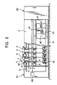
- Figure 2 is a schematic front view of the spinning apparatus and a yarn joining carriage according to the present invention.
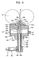
- Figure 3 is a side sectional view of a spinning member constituting the spinning apparatus according to the present invention.
- Figure 4 is a schematic side view including a control block and other components of the spinning apparatus according to the present invention.
- Figure 5 is a graph showing the relationship between the rotation speed of individual-spindle-driving motor and time during a joining operation.
- An embodiment of the present invention will be described below. However, the present invention is not limited to the present embodiment but other embodiments are possible unless they deviate from the spirits of the present invention.
- First, with reference to Figures 1 and 2, brief description will be given of a spinning unit constituting a spinning apparatus according to the present invention.
- 1 is a bundle of fibers accommodated in a
can 2. (D) is a 4-line draft device taken by way of example and composed of a plurality of draft rollers including a back roller 3, athird roller 4, asecond roller 5 around which anapron belt 5a is installed, and afront roller 6. (S) is a spinning member described later. 7 is a yarn feeding member composed of anip roller 7a and a delivery roller 7b. 8 is a slack tube in which a yarn discharged from the spinning member (S) that has resumed spinning is reserved. 9 is a yarn clearer. - 10 is a package wound around a
bobbin 12 supported by a bobbin holder 11. Thepackage 10 is configured so as to be rotated by having afriction roller 13 abutting against its surface. 14 is a traversing guide of a traversing device (not shown in the drawings). A winding member (W) is constituted by thebobbin 12 supported by the bobbin holder 11, thefriction roller 13, thetraversing guide 14, and others. - The bundle of fibers 1 drawn out from the
can 2 via aguide bar 15 is drafted by the draft device (D) and then enters the spinning member (S). The spinning member (S) then forms the fibers into a yarn. The yarn Y discharged by the spinning member (S) is fed toward thepackage 10 while being sandwiched between thenip roller 7a and thedelivery roller 7b, constituting theyarn feeding member 7. Then, while being traversed by the traversingguide 14, the yarn Y is wound around thepackage 10 which abuts against thefriction roller 13 and is rotating. - A spinning apparatus is composed of a large number of spinning units (U) arranged in line along a frame (F), the spinning units (U) each being composed of the draft device (D), the spinning device (S), the
yarn feeding member 7, theslack tube 8, the yarn clearer 9, the winding member (W), and others as described above. - As shown in Figure 2, E1 is a motor box disposed at one end of the spinning apparatus, and E2 is a blower box disposed at the other end of the spinning apparatus. (A) is a yarn joining carriage configured to run on a rail (R) disposed along a longitudinal direction of the spinning apparatus. On the yarn joining carriage (A) are disposed a well-known suction nozzle (a1) as spinning member side yarn capturing means, a well-known yarn joining device (a2) such as a knotter or a splicer, a well-known suction mouth (a3) as package side yarn capturing means, and the like.
- Now, the spinning member will be described with reference to Figure 3.
- As shown in Figure 3, 16 is a fiber introducing block having an
introduction port 16a into which the bundle of fibers 1 drafted by the draft device (D) and aneedle 16b disposed on a channel for the bundle of fibers 1. Thefiber introducing block 16 is fitted into an attachinghole 17a formed in a tip of thenozzle member 17. A substantially-cone-frustum-shaped space portion 17c having an innerperipheral wall 17b inclined to so as to diverge away from thefiber introducing block 16 is formed downstream of the attachinghole 17a, into which thefiber introducing block 16 has been fitted. 17d is a plurality of nozzle holes formed in thenozzle member 17 and located close to thefiber introducing block 16. 17e is a compressed air supply member in which an air passage 17e1 is formed so as to surround thenozzle holes 17d. The compressedair supply member 17e is connected to a compressed air supply source (not shown in the drawings). - 17f is a suction hole formed in a
cylindrical portion 17g of thenozzle member 17. Apipe 18 connected to an air suction source (not shown in the drawings) is connected to thesuction hole 17g. - 19 is a hollow guide shaft. The
hollow guide shaft 19 has a cone-frustum-shaped tip portion 19a and acylindrical portion 19c having an annularinternal air passage 19b. Ayarn passage 19d is formed along the axis of thehollow guide shaft 19. Theinternal air passage 19b and theyarn passage 19d are connected together via anauxiliary nozzle 19e. Further, apipe 21 connected to a compressed air supply source (not shown in the drawings) is connected to theinternal air passage 19b via a connectingmember 20 connected to a through-hole 19f formed in thecylindrical portion 19c. Theauxiliary nozzle 19e is configured to lie closer to thetip portion 19a than the through-hole 19f formed in thecylindrical portion 19c. Compressed air from the compressed air supply source enters theinternal air passage 19b via the connectingmember 20 and thepipe 21. Subsequently, the compressed air is injected from theauxiliary nozzle 19e and enters theyarn passage 19d formed in thehollow guide shaft 19. The air then flows toward ayarn discharge port 19g located opposite thetip portion 19a of thehollow guide shaft 19. - The
hollow guide shaft 19 is fitted into an attachinghole 22a formed in ashaft attaching member 22. Theshaft attaching member 22 is configured to be merged with thenozzle member 17 by fitting itsfitting portion 22b into thecylindrical portion 17g of thenozzle member 17. Further, the cone-frustum-shapedtip portion 19a of thehollow guide shaft 19 is arranged in the substantially-cone-frustum-shapedspace portion 17c. Thetip portion 19a is also arranged opposite theneedle 16b attached to thefiber introducing block 16. - Now, brief description will be given of a process of generating the yarn Y using the spinning unit constituting the spinning apparatus configured as described above.
- The bundle of fibers 1 is drawn out from the
can 2 and then supplied to the draft device (D). The bundle of fibers 1 is then drafted at a predetermined total draft ratio by the draft device (D). Then, the bundle of fibers 1 is introduced into the introducinghole 16a of thefiber introducing block 16 by a sucking air current generated near the introducinghole 16a owing to the action of air injected from thenozzle hole 17d in thenozzle member 17. Subsequently, the bundle of fibers 1 is fed along the periphery of theneedle 16b and enter a spinning chamber 17c1 located in thespace portion 17c, formed in thenozzle member 17, and between thetip portion 19a of thehollow guide shaft 19 and thefiber introducing block 16. - The fibers constituting the bundle of fibers 1 sucked into the spinning chamber 17c1 undergo the action of a whirling air current injected from the
nozzle hole 17d and whirling near thetip portion 19a of thehollow guide shaft 19. While being separated from the bundle of fibers 1, some of the fibers are reversedand wrapped around the outer periphery oftip portion 19a of thehollow guide shaft 19. Furthermore, the fibers are swung around the yarn Y being generated and is wrapped its outer periphery. The fibers are thus twisted in the direction of the whirling air current. Further, part of the twist applied by the whirling air current attempts to propagate toward thefront roller 6. However, theneedle 16b hinders the propagation to prevent the bundle of fibers 1 fed from thefront roller 6 from being twisted by this twist. The fibers twisted by the whirling air current are sequentially formed into the truly twisted-like yarn Y, composed of a core fiber and a wrapping fiber wound around the core fiber. Then, the yarn Y passes through theyarn passage 19d in thehollow guide shaft 19 and is then discharged from theyarn discharge port 19g. During such a normal process of generating the yarn Y, compressed air from the compressed air supply source is not supplied to theinternal air passage 19b in thehollow guide shaft 19 via thepipe 21 and the connectingmember 20. Consequently, the feeding of compressed air from theauxiliary nozzle 19e into theyarn passage 19d is not carried out. - In a normal spinning state, the yarn Y passes through the
yarn passage 19d in thehollow guide shaft 19 and then exits theyarn discharge port 19g. The yarn Y is then fed toward thepackage 10 while being sandwiched between thenip roller 7a anddelivery roller 7b, constituting theyarn feeding member 7. Subsequently, while being traversed by the traversingguide 14, the yarn Y is thus wound around thepackage 10, which abuts against thefriction rollers 13 and is rotating. - Now, description will be given of a yarn joining operation performed by the spinning apparatus configured as described above.
- At the start of spinning or when the yarn is broken, the back roller 3 and the
third roller 4 are stopped. Accordingly, the bundle of fibers 1 is cut between the stoppedthird roller 4 and thesecond roller 5, which is always rotated. The tip portion of the bundle of fibers 1 is gripped by the stoppedthird roller 4. For a yarn joining operation, the back roller 3 and thethird roller 4 are re-driven to feed out the bundle of fibers 1. The bundle of fibers 1 is also supplied to the spinning member (S) via thesecond roller 5 andfront roller 6, which are always rotationally driven. Simultaneously with the resumption of driving of the draft device (D), which has been stopped, compressed air starts to be injected from thenozzle hole 17d in thenozzle member 17 and from theauxiliary nozzle 19e in thehollow guide shaft 19. That is, during a yarn joining operation, compressed air is injected from thenozzle hole 17d in thenozzle member 17, while compressed air from the compressed air supply source is supplied to theinternal air passage 19b in thehollow guide shaft 19 via thepipe 21 and the connectingmember 20. Consequently, compressed air is also injected from theauxiliary nozzle 19e into thepassage 19d. - While whirling, the compressed air injected from the
nozzle hole 17d in thenozzle member 17 flows in the direction in which the bundle of fibers 1 is fed. - Thus, the bundle of fibers 1 introduced into the introducing
hole 16a in thefiber introducing block 16 is fed to the neighborhood of thetip portion 19a of thehollow guide shaft 19 via theneedle 16b, while being loosely falsely twisted by the whirling air current. Further, the compressed air injected from theauxiliary nozzle 19e flows along theyarn passage 19d formed in thehollow guide shaft 19, while forming a whirling air current. This compressed air also generates an air flow near anopening 19h formed in thetip portion 19a of thehollow guide shaft 19, the air flow flowing in a suction direction (toward the interior of the hollow guide shaft 19). Thus, the bundle of fibers 1 can be continuously drawn into theyarn passage 19d in thehollow guide shaft 19. - The falsely twisted bundle of fibers 1 fed to the neighborhood of the
opening 19h formed in thetip portion 19a of thehollow guide shaft 19, is sucked into theyarn passage 19d through theopening 19h. Then, in theyarn passage 19d, the bundle of fibers 1 is exposed to the whirling air current generated by the compressed air injected from theauxiliary nozzle 19e. The loosely falsely twisted bundle of fibers 1 is spun into a fasciated-fibers-like yarn (fasciated yarn) by the whirling air current generated in the spinning chamber 17c1 by the compressed air injected from thenozzle hole 17d in thenozzle member 17 as well as the whirling air current generated in theyarn chamber 19d in thehollow guide shaft 19 by the compressed air injected from theauxiliary nozzle 19e in thehollow guide shaft 19. At the same time, the yarn is discharged from theyarn discharge port 19g in thehollow guide shaft 19. - The term "yarn discharging spinning" refers to the state in which after yarn breakage, the back roller 3 and the
third roller 4 are re-driven to restart feeding the bundle of fibers 1 to spin a fasciated-fibers-like yarn using the compressed air injected from thenozzle hole 17d in thenozzle member 17 as well as the compressed air injected from theauxiliary nozzle 19e formed in thehollow guide shaft 19, as described above. - Once an appropriate time has passed after the above described yarn discharging spinning, the compressed air stops being fed from the compressed air supply source to the
internal air passage 19b in thehollow guide shaft 19, and the compressed air stops being injected from theauxiliary nozzle 19e into theyarn passage 19d. Then, the whirling air current in thehollow guide shaft 19 disappears to bring the apparatus into a normal spinning state. - Spinning of the yarn Y is resumed as described above. The yarn Y is sucked into the well-known suction nozzle (a1), which is disposed in the yarn joining carriage (A) stopped at the position of the spinning unit U that is to perform a yarn joining operation and is rotationally movable to the neighborhood of the
yarn discharge port 19g in thehollow guide shaft 19, by its upward rotational movement. Subsequently, as the suction nozzle (a1) rotationally moves downward, the yarn Y is introduced into the well-known yarn joining device (a2), disposed in the yarn joining carriage (A). While being guided toward the yarn joining device (a2) by the suction nozzle (a1), the yarn Y is sandwiched between thenip roller 7a and thedelivery roller 7b, constituting theyarn feeding member 7. On the other hand, the terminal portion of the yarn Y wound around thepackage 10 is sucked into the well-known suction mouth (a3), disposed in the yarn joining carriage (A). Subsequently, as the suction mouth (a3) rotationally moves upward, the terminal portion of the yarn Y is introduced into the yarn joining device (a2). Then, the yarn Y generated by the spinning member (S) and the yarn Y drawn out from thepackage 10 are both introduced into the yarn joining device (a2). The yarn joining device (a2) is then driven to join both yarns Y to complete the yarn joining operation. The extra yarn Y generated during the yarn joining operation is reserved in theslack tube 8. - Now, with reference to Figures 2 and 4, description will be given of operations and driving control of the draft device (D), spinning member (S),
yarn feeding member 7,yarn clearer 9, and winding member (W), and others. - M1 is a individual-spindle-driving motor arranged for each spinning unit U to drive the back roller 3 and the
third roller 4. The back roller 3 and thethird roller 4 are rotationally driven using an endless belt (b1) extended between apulley 3a attached to the back roller 3 and apulley 4a attached to thethird roller 4 and a pulley (m1) attached to an output shaft of the individual-spindle-driving motor M1. The individual-spindle-driving motor M1 is configured to have its rotation speed controlled by a central control device C1 as a higher controller via a motor driver MD1. In this case, the individual-spindle-driving motor M1 may be a stepping motor. This eliminates the need for a rotation detector such as an encoder to enable control using an open loop. - M2 is a common motor that rotationally drives the
second roller 5 via a transmission T1 and that rotationally drives thefront roller 6, thedelivery roller 7b, constituting theyarn feeding member 7, and thefriction roller 13. This single common motor M2 is disposed in the motor box E1 and shared by the plurality of spinning units U, constituting the spinning apparatus. The common motor M2 is configured to be controlled, via a motor driver MD2, by a central control device C2 as a higher controller disposed in the motor box E1. Then, if the common motor M2 is accelerated or decelerated via the motor driver MD2 according to a command from the central control device C2, thesecond roller 5, thefront roller 6, theyarn feeding member 7, and thefriction roller 13 are controlled to synchronize with one another while maintaining a predetermined rotation speed ratio. Since the back roller 3, thethird roller 4, thesecond roller 5, and thefront roller 6 rotate at different rotation speeds, it is possible to perform a drafting operation at a predetermined total draft ratio. - The thickness (yarn count) of the yarn generated depends mainly on the amount of fibers discharged from the
front roller 6 and supplied to the spinning member (S). With the conventional spinning apparatus, even during a yarn joining operation in the spinning apparatus, the same amount of fibers as that used for the normal yarn generating operation is supplied to the spinning member (S) by the draft device (D). - However, if an inappropriate amount of fibers are supplied during yarn discharging spinning for a yarn joining operation, the yarn discharging spinning may fail. For example, it is assumed that yarn breakage occurs while a spun yarn Y of a smaller yarn count is being generated. Then, when the above described yarn discharging spinning is carried out by supplying the spinning member (S) with the same amount of fibers as that used for a normal operation of generating a yarn of a smaller yarn count, the amount of fibers is small and insufficient to bundle the fibers in generating a fasciated yarn for the yarn spinning discharging. Thus, the yarn generation for the yarn discharging spinning may fail. For example, if the yarn discharging spinning is carried out at high speed, the fibers are not sufficiently bundled because they are exposed to a whirling air current only a short time and for the above described reason.
- Consequently, the yarn generated is not strong enough to endure being spun out downward. In contrast, it is assumed that yarn breakage occurs while a spun yarn of a larger yarn count is being generated. Then, when the above described yarn discharging spinning is carried out by supplying the spinning member (S) with the same amount of fibers as that used for a normal operation of generating a yarn of a larger yarn count, the amount of fibers so large that the
opening 19h in thehollow guide shaft 19 of the spinning member (S) may be filled with the fibers. Thus, the yarn generation for the yarn discharging spinning may fail. - Referring mainly to Figure 4 and Figure 5, showing the relationship between the rotation speed of the individual-spindle-driving motor M1 and time during a yarn joining operation, description will be given of a yarn joining operation according to an embodiment of the present invention which operation improves the success rate of the above described yarn discharging spinning.
- If the yarn Y generated has a defective part such as a thicker portion such as a slab or a thinner portion, the defective potion is detected by the
yarn clearer 9. The yarn Y the defective portion of which has been detected is cut by the cutter. A part of the cut yarn Y which is connected to thepackage 10 is wound around thepackage 10. A yarn defective-part detection signal from theyarn clearer 9 is inputted to the central control device C1 as shown in Figure 4. On the basis of this yarn defective-part detection signal, the central control device C1 stops driving of the individual-spindle-driving motor M1 via the motor driver MD1. Then, the back roller 3 and thethird roller 4 stops rotating to cut the bundle of yarns 1 between thesecond roller 5, which are always rotated, and the third roller 4 (time T1 in Figure 5). The bundle of fibers 1 fed out from thesecond roller 5 and thefront roller 6, which are always rotated, is supplied to the spinning member (S), which is still being driven. The bundle of fibers 1 is then formed into a yarn Y. The yarn Y generated is sucked into a duct (not shown in the drawings) for removal, the duct being located immediately upstream of the cutter. Subsequently, compressed air stops being injected from thenozzle hole 17d formed in thenozzle member 17, constituting the spinning member (S), to stop the operation of the spinning member (S). Further, thepackage 10 is separated from thefriction roller 13 to stop rotating. - Subsequently, the above described yarn discharging spinning is carried out. However, for example, if yarn breakage occurs while a spun yarn Y of a smaller yarn count is being generated, when the above described yarn discharging spinning is carried out by supplying the spinning member (S) with the same amount of fibers as that used for a normal operation of generating a yarn of a smaller yarn count, the yarn discharging spinning may fail because of the small amount of fibers. Accordingly, in the present embodiment, in resuming the spinning process, the central control device C1 increases the rotation speed of the individual-spindle-driving motor M1, which rotationally drives the back roller 3 and the
third roller 4, via the motor driver MD1 compared to the normal spinning. This reduces the total draft ratio and increase the amount of fibers supplied to the spinning member (S). This is because during the normal spinning, thesecond roller 5 rotates faster than the back roller 3 and thethird roller 4 and because during the normal spinning, thefront roller 6 rotates faster than thesecond roller 5. In particular, the difference in rotation speed between thesecond roller 5 and thefront roller 6 is set to be larger than the other differences. - According to a command from the central control device C1, the back roller 3 and the
third roller 4 are re-driven to feed out the bundle of fibers 1, the tip of which is gripped by thethird roller 4, which is stopped (time T2 in Figure 5). Further, as described above, according to a command from the central control device C1, the back roller 3 and thethird roller 4 are rotated faster than in the normal spinning state to reduce the total draft ratio of the draft device (D). Thus, fibers the amount of which is larger than that used for the normal yarn generating process are supplied to the spinning member (S) via thesecond roller 5 and the front roller 6 (time T3 in Figure 5). Substantially simultaneously with the resumption of driving of the draft device (D), which has been stopped, compression air restarts to be injected from thenozzle hole 17d formed in thenozzle member 17, constituting the spinning member (S). Further, compressed air is injected from theauxiliary nozzle 19e formed in thehollow guide shaft 19. Thus, yarn discharging spinning is carried out as described above. As a result, the central control device C1 operates as fiber supply amount control means and total draft ratio change control means for switching the amount of fibers supplied per unit time and the total draft ratio, respectively, between the yarn discharging spinning and the normal spinning. - The yarn Y generated by the yarn discharging spinning is discharged from the
yarn discharge port 19g in thehollow guide shaft 19. The yarn Y is sucked into the suction nozzle (a1), which is disposed in the yarn joining carriage (A) and is positioned close to theyarn discharge port 19g, by its upward rotational movement, and the yarn Y is thus captured (time T4 in Figure 5). Subsequently, as the suction nozzle (a1) rotationally moves downward, the yarn Y sucked and captured by the suction nozzle (a1) is introduced into the yarn joining device (a2), disposed in the yarn joining carriage (A). While being guided toward the yarn joining device (a2) by the suction nozzle (a1), the yarn Y is sandwiched between thenip roller 7a and thedelivery roller 7b, constituting theyarn feeding member 7, and the yarn Y then starts being fed and is thus stably fed out (time T5 in Figure 5). - Further, concurrently with the above described operation performed by the suction nozzle (a1) to introduce the yarn Y into the yarn joining device (a2), a suction port in the suction mouth (a3), also disposed in the yarn joining carriage (A), is moved closer to the
package 10 being rotated by a reversing roller (not shown in the drawings) in the direction opposite to a winding direction. The yarn Y wound around thepackage 10 is thus sucked. Furthermore, the suction mouth (a3) is rotationally moved upward to introduce the yarn Y into the yarn joining device (a2). Then, the yarn Y generated by the spinning member (S) and the yarn Y drawn out from thepackage 10 are introduced into the yarn joining device (a2). The yarn joining device (a2) is then driven to join both yarns Y to complete the yarn joining operation (time T8 in Figure 5). The extra yarn Y generated during the yarn joining operation is temporarily reserved in theslack tube 8. Further, a thicker portion of the yarn generated on the basis of the changed total draft ratio is disposed of during the yarn joining operation performed by the yarn joining device (a2). Consequently, such a thicker portion is not wound around thepackage 10. - Also during the above described yarn discharging spinning, the
second roller 5,front roller 6,yarn feeding member 7, andfriction roller 13, rotationally driven by the common motor M2, are controlled to synchronize with one another as in the case with the normal spinning process. - During the above described yarn discharging spinning process, the changed total draft ratio is more preferably returned to the normal total draft ratio after the
yarn feeding member 7 as a yarn feeding device has started exerting force for feeding the yarn Y (time T5 in Figure 5), particularly after the yarn discharging spinning has completed (time T6 in Figure 5). As a result, the yarn count is changed after theyarn feeding member 7 has started feeding the yarn stably. Therefore, the end of the spun-out yarn can be more reliably fed out downstream. The yarn discharging spinning is carried out between the above described time T2 and T6. Subsequently, at the time T6, the compressed air stops being injected from theauxiliary nozzle 19e. Then, the normal true-twisting-like spinning process is resumed. Further, the central control device C1 detects the time elapsing after the start of the yarn discharging spinning to determine whether or not the timing has been reached with which theyarn feeding member 7 starts exerting force for feeding the yarn Y. On the basis of this detection, via the motor driver MD1, the rotation of the individual-spindle-driving motor M1 is returned to the rotation speed for the normal yarn generating process (time T7 in Figure 5). Alternatively, to determine the timing for the time t7 in Figure 5, a yarn detecting sensor may be disposed in the suction nozzle (a1) to eliminate the need for the central control unit C1 to detect that theyarn feeding member 7 has started exerting force for feeding the yarn Y. This enables the apparatus to more reliably detect that the yarn discharging spinning has succeeded and that the yarn spun out by this spinning has been successfully captured. Alternatively, instead of causing the central control device C1 to detect the above described elapsed time, it is possible to return, during the yarn discharging spinning, the changed total draft ratio to the normal total draft ratio when or immediately after the suction nozzle (a1) positioned close to theyarn discharge port 19g starts to rotationally move downward after sucking and capturing the yarn Y discharged from theyarn discharge port 19g in thehollow guide shaft 19. This arrangement enables the minimization of length of a thicker portion of the yarn generated (between time t3 and time t7 in Figure 5) on the basis of the changed total draft ratio. This serves to avoid the situation in which part of such a thicker portion fails to be disposed of and is used for joining and thus wound around thepackage 10. - On the other hand, during a normal yarn generating process, if yarn breakage occurs while a spun yarn Y of a larger yarn count is being generated, when the above described yarn discharging spinning is carried out by supplying the spinning member (S) with the same amount of fibers as that used for a normal operation of generating a yarn of a larger yarn count, the amount of fibers so large that the
opening 19h in thehollow guide shaft 19, constituting the spinning member (S), may be filled with the fibers. Thus, the yarn discharging spinning may fail. In such a case, in resuming the spinning process, the central control device C1 reduces the rotation speed of the individual-spindle-driving motor M1 via the motor driver MD1. This raises the total draft ratio and reduces the amount of fibers supplied to the spinning member (S). This operation is the same as that in the above described embodiment except that the amount of fibers supplied to the spinning member (S). Its detailed description is thus omitted. - As described above, the success rate of the yarn discharging spinning can be improved by controlling the rotation speeds of the back roller 3 and
third roller 4, constituting the draft device (D), to change the total draft ratio of the draft device (D) to properly adjust the amount of fibers supplied to the spinning member (S). - Further, the total draft ratio is changed by controlling the rotation speeds of the back roller 3 and the
third roller 4 without controlling the rotation speed of thefront roller 6. Consequently, the spinning speed of the yarn Y remains unchanged. This allows the success rate of the yarn discharging spinning to be improved even if the spinning speed of the normal spinning is high speed. It is unnecessary to change the rotation speed of thesecond roller 5,front roller 6,yarn feeding member 7, orfriction roller 13, i.e. the rotation speed of the common motor M2, which executes synchronous control, even when the spinning speed is changed. Therefore, the yarn discharging spinning can be stably carried out. It is also possible to simplify the control of the spinning apparatus. - The above described embodiment shows the example in which during the yarn discharging spinning, the rotation speed of the individual-spindle-driving motor M1, which rotationally drives the back roller 3 and the
third roller 4, is changed according to a command from the central control device C1. However, the back roller 3 and thethird roller 4 may be rotationally moved by the common motor M2, disposed in the motor box E1, whereas thefront roller 6 may be rotationally moved by the individual-spindle-driving motor M1. In this case, the total draft ratio of the draft device (D) can be increased by increasing the rotation speed of the individual-spindle-driving motor M1 and thus the rotation speed of thefront roller 6. In contrast, the total draft ratio of the draft device (D) can be reduced by reducing the rotation speed of the individual-spindle-driving motor M1 and thus the rotation speed of thefront roller 6. This is because during the normal spinning, thesecond roller 5 rotates faster than the back roller 3 and thethird roller 4, and because during the normal spinning, thefront roller 6 rotates faster than thesecond roller 5. In particular, the difference in rotation speed between thesecond roller 5 and thefront roller 6 is set to be larger than the other differences. - Thus, in particular, when the yarn Y of a smaller yarn count is spun, if during the yarn discharging spinning, the rotation speed of the individual-spindle-driving motor M1 is lowered to reduce the draft ratio of the draft device (D), then a yarn of a large yarn count is obtained during the yarn discharging spinning, and the spinning speed can be reduced. It is thus possible to allow whirling air currents from the
nozzle hole 17d andauxiliary nozzle 19e to more reliably act on the bundle of fibers. Therefore, the success rate of the yarn discharging spinning can be further improved. - As described above, if the rotation speed of the
front roller 6 is changed to change the total draft ratio of the draft device (D) , then the resulting spining speed (yarn generation speed) of the spinning member (S) differs from the one used in the normal spinning state. Accordingly, in such a case, the motor driver MD1 may give a command to change the rotation speeds of thesecond roller 5,yarn feeding member 7, andfriction roller 13 so as to control thesecond roller 5, theyarn feeding member 7, and thefriction roller 13 so as to synchronize with one another. - The spinning member (S) need not be composed of the
nozzle hole 17d and thehollow guide shaft 19 in which theauxiliary nozzle 19e are formed. For example, a fasciated yarn may be generated using two nozzles that whirling air currents in different directions. Alternatively, a fasciated yarn may be generated using one nozzle and a pair of twisting rollers. - The present invention is configured as described above and thus produces the effects described below.
- Before the yarn discharging spinning, the amount of fibers supplied per unit time in the normal spinning state is changed to the amount of fibers supplied per unit time during the yarn discharging spinning, the latter amount being different from the former amount. Therefore, the success ratio of the yarn joining increases.
- The yarn feeding device is provided which exerts feeding force on a yarn spun out by the spinning member, and on the basis of the timing with which yarn feeding device starts exerting yarn feeding force, the changed amount of fibers supplied is returned to the amount of fibers supplied in the normal spinning state. Consequently, the yarn count is changed after the yarn feeding member has started feeding the yarn stably. This enables the spun-out yarn to be more reliably fed out downstream.
- At least one of the plurality of draft rollers constituting the draft device and rotating at different speeds is driven by the motor that drives each spinning unit. The control means is disposed which controls the rotation speed of the motor for each spinning unit. Consequently, it is possible to change the total draft ratio of the spinning unit which needs the yarn discharging spinning without influence on other spinning units which perform the normal spinning.
Claims (12)
- A spinning method of drafting supplied fibers (1) at a predetermined total draft ratio and then spinning the fibers using a spinning member (S) composed of a nozzle member (17) having a nozzle hole (17d), the method being characterized in that before yarn discharging spinning, the amount of fibers supplied to said spinning member (17) per unit time in,a normal spinning state is changed to the amount of fibers supplied per unit time during the yarn discharging spinning, the latter amount being different from the former amount, and after the yarn discharging spinning has ended, the changed amount of fibers supplied is returned to the amount of fibers supplied in the normal spinning state.
- A spinning method according to Claim 1, characterized in that a yarn feeding device is provided which exerts feeding force on a yarn spun out by said spinning member, and on the basis of a timing with which the yarn feeding device starts exerting yarn feeding force, said changed amount of fibers supplied is returned to the amount of fibers supplied in the normal spinning state.
- A spinning method according to Claim 1 or Claim 2, characterized in that said amount of fibers supplied can be changed by changing, before the yarn discharging spinning, the total draft ratio to one different from the total draft ratio used in the normal spinning state, and returning said changed total draft ratio to the total draft ratio used in the normal spinning state, after the yarn discharging spinning has ended.
- A spinning method according to any one of Claim 1 to Claim 3, characterized in that said spinning member is composed of a nozzle member having a nozzle hole and a hollow guide shaft, and for a yarn joining operation, the yarn discharging spinning is carried out by injecting a whirling air current from said nozzle member and injecting compressed air from an auxiliary nozzle formed in the hollow guide shaft, into a yarn passage to generate suction force directed from an opening formed in a tip of the hollow guide shaft, toward a yarn discharge port.
- A spinning apparatus comprising a draft device (D) which drafts supplied fibers and a spinning member (S) composed of a nozzle member (17), the apparatus being characterized by further comprising fiber supply amount control means which can operate to switch the amount of fibers per unit time supplied to the spinning member by the draft device in a normal spinning state, to the amount of fibers supplied to the spinning member by the draft device during yarn discharging spinning and normal spinning state.
- A spinning apparatus according to Claim 5, characterized by further comprising a yarn feeding device which exerts feeding force on a yarn spun out by said spinning member, and in that said controls means provides such control that the changed amount of fibers supplied is returned to the amount of fibers supplied in the normal spinning state, on the basis of a timing with which the yarn feeding device starts exerting yarn feeding force.
- A spinning apparatus according to Claim 5 or Claim 6, characterized in that said control means is total draft ratio change control means which can change a total draft ratio of said draft device used in a normal spinning state to one for yarn discharging spinning.
- A spinning apparatus according to Claim 7, characterized by comprising a plurality of spinning units arranged in line and each comprising said draft device and spinning member, and in that the draft device is composed of a plurality of draft rollers rotating at different rotation speeds, and at least one of said plurality of rollers can be controlled to rotate at one of different speeds corresponding to the respective spinning units.
- A spinning apparatus according to Claim 8, characterized in that the roller that can be controlled to rotate at one of the different speeds corresponding to the respective spinning units is different from a front roller.
- A spinning apparatus according to Claim 8 or Claim 9, characterized in that said at least one of said plurality of rollers is driven by a motor that drives a corresponding one of the spinning units, and control means is disposed which controls the rotation speed of said motor for each spinning unit.
- A spinning apparatus according to Claim 10, characterized in that said motor is a stepping motor.
- A spinning apparatus according to any one of Claim 5 to Claim 11, characterized in that said spinning member is composed of a nozzle member and a hollow guide shaft, and an auxiliary nozzle is provided which injects, during yarn discharging spinning, compressed air into a passage in the hollow guide shaft to generate suction force directed from an opening formed in a tip of the hollow guide shaft, toward a yarn discharge port.
Applications Claiming Priority (2)
| Application Number | Priority Date | Filing Date | Title |
|---|---|---|---|
| JP2002073711A JP3575470B2 (en) | 2002-03-18 | 2002-03-18 | Spinning method and apparatus |
| JP2002073711 | 2002-03-18 |
Publications (4)
| Publication Number | Publication Date |
|---|---|
| EP1347085A2 EP1347085A2 (en) | 2003-09-24 |
| EP1347085A3 EP1347085A3 (en) | 2004-01-14 |
| EP1347085B1 true EP1347085B1 (en) | 2006-10-25 |
| EP1347085B2 EP1347085B2 (en) | 2010-04-21 |
Family
ID=27785144
Family Applications (1)
| Application Number | Title | Priority Date | Filing Date |
|---|---|---|---|
| EP03005279A Expired - Lifetime EP1347085B2 (en) | 2002-03-18 | 2003-03-10 | Vortex spinning method and apparatus |
Country Status (4)
| Country | Link |
|---|---|
| EP (1) | EP1347085B2 (en) |
| JP (1) | JP3575470B2 (en) |
| CN (1) | CN1332084C (en) |
| DE (1) | DE60309233T3 (en) |
Cited By (3)
| Publication number | Priority date | Publication date | Assignee | Title |
|---|---|---|---|---|
| CN101319417B (en) * | 2007-06-04 | 2011-11-09 | 村田机械株式会社 | Spinning machine |
| CN101498067B (en) * | 2008-01-29 | 2012-06-27 | 欧瑞康纺织有限及两合公司 | Air-jet spinning device |
| KR101819111B1 (en) | 2016-02-05 | 2018-01-16 | 삼일방 (주) | Manufacturing Method Of High Twist Airjet Spun Yarn Having Excellent Uniformity, Stress And Strain, Friction Resistance |
Families Citing this family (11)
| Publication number | Priority date | Publication date | Assignee | Title |
|---|---|---|---|---|
| DE102007023488B4 (en) * | 2007-05-19 | 2014-06-12 | Saurer Germany Gmbh & Co. Kg | Air spinning machine |
| CN102304788B (en) * | 2007-06-04 | 2014-07-30 | 村田机械株式会社 | Spinning device |
| JP5924860B2 (en) * | 2010-12-03 | 2016-05-25 | 株式会社豊田自動織機 | Control method and control device for drafting device in pre-spinning process |
| JP2013067882A (en) * | 2011-09-21 | 2013-04-18 | Murata Mach Ltd | Yarn winding machine, and method of producing spun yarn |
| KR101432928B1 (en) | 2013-03-11 | 2014-08-21 | 삼일방 (주) | Process of producing polyester/lyocell air-jet belnded spun yarn having exellent sweat-absorbing and rapid-drying and antibacterial property |
| KR101406500B1 (en) | 2013-03-11 | 2014-06-11 | 삼일방 (주) | Process of producing aramid air-jet belnded spun yarn having exellent appearance and friction resistance |
| JP2016017254A (en) * | 2014-07-10 | 2016-02-01 | 村田機械株式会社 | Spinning machine and spinning method |
| JP2016023391A (en) * | 2014-07-24 | 2016-02-08 | 村田機械株式会社 | Spinning machine and spinning method |
| JP2018090923A (en) * | 2016-12-01 | 2018-06-14 | 村田機械株式会社 | Spinning machine and spinning method |
| JP2019026981A (en) * | 2017-08-02 | 2019-02-21 | 村田機械株式会社 | Air spinning machine and display control method |
| EP3505661A1 (en) * | 2017-12-28 | 2019-07-03 | Murata Machinery, Ltd. | Spinning machine and spinning method |
Family Cites Families (8)
| Publication number | Priority date | Publication date | Assignee | Title |
|---|---|---|---|---|
| US5022123A (en) * | 1988-09-29 | 1991-06-11 | Murata Kikai Kabushiki Kaisha | Draft mechanism having roller pairs connected to draft ratio controlled motors by timing belts |
| US5524427A (en) * | 1992-11-10 | 1996-06-11 | Howa Machinery, Ltd. | Method and apparatus for piecing slivers in a spinning machine by throttling in a nozzle |
| JP3480079B2 (en) * | 1994-10-24 | 2003-12-15 | 株式会社豊田自動織機 | Starting method and starting control device for spinning machine |
| JPH09111546A (en) * | 1995-10-12 | 1997-04-28 | Murata Mach Ltd | Spinning machinery |
| DE19917968B4 (en) † | 1999-04-21 | 2007-08-23 | Saurer Gmbh & Co. Kg | Service unit for a textile machine producing cross-wound bobbins |
| EP1072702B1 (en) * | 1999-07-28 | 2004-03-31 | Murata Kikai Kabushiki Kaisha | Spinning device and method |
| DE50111354D1 (en) † | 2000-12-22 | 2006-12-14 | Rieter Ag Maschf | Process for the preparation of a yarn formed in a spinning station or for piecing, as well as for the implementation of the method equipped spinning station |
| JP2003166132A (en) † | 2001-11-28 | 2003-06-13 | Murata Mach Ltd | Spinning machinery and spinning method |
-
2002
- 2002-03-18 JP JP2002073711A patent/JP3575470B2/en not_active Expired - Fee Related
-
2003
- 2003-03-10 EP EP03005279A patent/EP1347085B2/en not_active Expired - Lifetime
- 2003-03-10 DE DE2003609233 patent/DE60309233T3/en not_active Expired - Lifetime
- 2003-03-18 CN CNB03121696XA patent/CN1332084C/en not_active Expired - Lifetime
Cited By (3)
| Publication number | Priority date | Publication date | Assignee | Title |
|---|---|---|---|---|
| CN101319417B (en) * | 2007-06-04 | 2011-11-09 | 村田机械株式会社 | Spinning machine |
| CN101498067B (en) * | 2008-01-29 | 2012-06-27 | 欧瑞康纺织有限及两合公司 | Air-jet spinning device |
| KR101819111B1 (en) | 2016-02-05 | 2018-01-16 | 삼일방 (주) | Manufacturing Method Of High Twist Airjet Spun Yarn Having Excellent Uniformity, Stress And Strain, Friction Resistance |
Also Published As
| Publication number | Publication date |
|---|---|
| CN1332084C (en) | 2007-08-15 |
| EP1347085A2 (en) | 2003-09-24 |
| DE60309233T3 (en) | 2010-12-30 |
| DE60309233D1 (en) | 2006-12-07 |
| CN1445394A (en) | 2003-10-01 |
| JP2003278035A (en) | 2003-10-02 |
| DE60309233T2 (en) | 2007-09-06 |
| EP1347085A3 (en) | 2004-01-14 |
| JP3575470B2 (en) | 2004-10-13 |
| EP1347085B2 (en) | 2010-04-21 |
Similar Documents
| Publication | Publication Date | Title |
|---|---|---|
| JP4801146B2 (en) | Spinning resumption method, spinning apparatus and jet spinning machine in a jet spinning machine | |
| US5511373A (en) | Method and apparatus for piecing a sliver and at least one of a leading yarn and a bobbin yarn | |
| EP1347085B1 (en) | Vortex spinning method and apparatus | |
| EP1826299B1 (en) | Spinning device | |
| JP2002069760A (en) | Production apparatus and method for core yarn | |
| US4545193A (en) | Method for piecing fasciated yarn | |
| EP1072702B1 (en) | Spinning device and method | |
| EP0807699B1 (en) | Piecing method and device for a spinning machine | |
| US5809764A (en) | Piecing method for a spinning machine | |
| CN110892102A (en) | Method for operating an open-end spinning device, yarn guide channel and open-end spinning machine comprising such a yarn guide channel | |
| EP2573030B1 (en) | Yarn winding machine | |
| US6959532B2 (en) | Method and device of piecing or starting of spinning for spinning positions of air spinning frames | |
| EP1316631A1 (en) | Spinning device and spinning method | |
| US6453656B1 (en) | Piecing method and piecing device for the spinning machine | |
| JP2008517166A (en) | Method for preparing a splicing operation in an air jet spinning device | |
| JP3341726B2 (en) | Spinning equipment | |
| JPH09268446A (en) | Piecing in fine spinning frame | |
| JP2001159039A (en) | Piecing device | |
| JP2560474B2 (en) | Operating method in spinning device | |
| JP2003268637A (en) | Spinning device and yarn ending method | |
| WO2012164435A1 (en) | An improved piecing mechanism in an air spinning machine | |
| JP2626500B2 (en) | Splicing method for spinning device | |
| JPH11100731A (en) | Piecing of spinning machine | |
| CN111793863A (en) | Spinning method and spinning machine | |
| JPH11107066A (en) | Piecing device in spinning machine |
Legal Events
| Date | Code | Title | Description |
|---|---|---|---|
| PUAI | Public reference made under article 153(3) epc to a published international application that has entered the european phase |
Free format text: ORIGINAL CODE: 0009012 |
|
| AK | Designated contracting states |
Kind code of ref document: A2 Designated state(s): AT BE BG CH CY CZ DE DK EE ES FI FR GB GR HU IE IT LI LU MC NL PT SE SI SK TR |
|
| AX | Request for extension of the european patent |
Extension state: AL LT LV MK RO |
|
| PUAL | Search report despatched |
Free format text: ORIGINAL CODE: 0009013 |
|
| AK | Designated contracting states |
Kind code of ref document: A3 Designated state(s): AT BE BG CH CY CZ DE DK EE ES FI FR GB GR HU IE IT LI LU MC NL PT SE SI SK TR |
|
| AX | Request for extension of the european patent |
Extension state: AL LT LV MK RO |
|
| 17P | Request for examination filed |
Effective date: 20040427 |
|
| AKX | Designation fees paid |
Designated state(s): CH DE LI |
|
| GRAP | Despatch of communication of intention to grant a patent |
Free format text: ORIGINAL CODE: EPIDOSNIGR1 |
|
| GRAS | Grant fee paid |
Free format text: ORIGINAL CODE: EPIDOSNIGR3 |
|
| GRAA | (expected) grant |
Free format text: ORIGINAL CODE: 0009210 |
|
| AK | Designated contracting states |
Kind code of ref document: B1 Designated state(s): CH DE LI |
|
| REG | Reference to a national code |
Ref country code: CH Ref legal event code: EP |
|
| REF | Corresponds to: |
Ref document number: 60309233 Country of ref document: DE Date of ref document: 20061207 Kind code of ref document: P |
|
| REG | Reference to a national code |
Ref country code: CH Ref legal event code: NV Representative=s name: E. BLUM & CO. AG PATENT- UND MARKENANWAELTE VSP |
|
| PLBI | Opposition filed |
Free format text: ORIGINAL CODE: 0009260 |
|
| PLBI | Opposition filed |
Free format text: ORIGINAL CODE: 0009260 |
|
| 26 | Opposition filed |
Opponent name: OERLIKON TEXTILE GMBH & CO. KG Effective date: 20070723 |
|
| 26 | Opposition filed |
Opponent name: MASCHINENFABRIK RIETER AG Effective date: 20070725 Opponent name: OERLIKON TEXTILE GMBH & CO. KG Effective date: 20070723 |
|
| PLAX | Notice of opposition and request to file observation + time limit sent |
Free format text: ORIGINAL CODE: EPIDOSNOBS2 |
|
| PLBB | Reply of patent proprietor to notice(s) of opposition received |
Free format text: ORIGINAL CODE: EPIDOSNOBS3 |
|
| PLAY | Examination report in opposition despatched + time limit |
Free format text: ORIGINAL CODE: EPIDOSNORE2 |
|
| PLBC | Reply to examination report in opposition received |
Free format text: ORIGINAL CODE: EPIDOSNORE3 |
|
| PLAB | Opposition data, opponent's data or that of the opponent's representative modified |
Free format text: ORIGINAL CODE: 0009299OPPO |
|
| PLAY | Examination report in opposition despatched + time limit |
Free format text: ORIGINAL CODE: EPIDOSNORE2 |
|
| PLBC | Reply to examination report in opposition received |
Free format text: ORIGINAL CODE: EPIDOSNORE3 |
|
| PUAH | Patent maintained in amended form |
Free format text: ORIGINAL CODE: 0009272 |
|
| STAA | Information on the status of an ep patent application or granted ep patent |
Free format text: STATUS: PATENT MAINTAINED AS AMENDED |
|
| 27A | Patent maintained in amended form |
Effective date: 20100421 |
|
| AK | Designated contracting states |
Kind code of ref document: B2 Designated state(s): CH DE LI |
|
| REG | Reference to a national code |
Ref country code: CH Ref legal event code: AEN Free format text: AUFRECHTERHALTUNG DES PATENTES IN GEAENDERTER FORM |
|
| REG | Reference to a national code |
Ref country code: DE Ref legal event code: R082 Ref document number: 60309233 Country of ref document: DE Representative=s name: PATENTANWAELTE WEICKMANN & WEICKMANN, DE Ref country code: DE Ref legal event code: R082 Ref document number: 60309233 Country of ref document: DE Representative=s name: WEICKMANN & WEICKMANN PATENTANWAELTE - RECHTSA, DE Ref country code: DE Ref legal event code: R082 Ref document number: 60309233 Country of ref document: DE Representative=s name: WEICKMANN & WEICKMANN PATENT- UND RECHTSANWAEL, DE |
|
| PGFP | Annual fee paid to national office [announced via postgrant information from national office to epo] |
Ref country code: DE Payment date: 20200320 Year of fee payment: 18 |
|
| PGFP | Annual fee paid to national office [announced via postgrant information from national office to epo] |
Ref country code: CH Payment date: 20200319 Year of fee payment: 18 |
|
| REG | Reference to a national code |
Ref country code: DE Ref legal event code: R119 Ref document number: 60309233 Country of ref document: DE |
|
| REG | Reference to a national code |
Ref country code: CH Ref legal event code: PL |
|
| PG25 | Lapsed in a contracting state [announced via postgrant information from national office to epo] |
Ref country code: LI Free format text: LAPSE BECAUSE OF NON-PAYMENT OF DUE FEES Effective date: 20210331 Ref country code: CH Free format text: LAPSE BECAUSE OF NON-PAYMENT OF DUE FEES Effective date: 20210331 Ref country code: DE Free format text: LAPSE BECAUSE OF NON-PAYMENT OF DUE FEES Effective date: 20211001 |