EP1346892A2 - Method and system for assisting driver of motor vehicle with deceleration control - Google Patents
Method and system for assisting driver of motor vehicle with deceleration control Download PDFInfo
- Publication number
- EP1346892A2 EP1346892A2 EP03002180A EP03002180A EP1346892A2 EP 1346892 A2 EP1346892 A2 EP 1346892A2 EP 03002180 A EP03002180 A EP 03002180A EP 03002180 A EP03002180 A EP 03002180A EP 1346892 A2 EP1346892 A2 EP 1346892A2
- Authority
- EP
- European Patent Office
- Prior art keywords
- driver
- degree
- vehicle
- motor vehicle
- braking torque
- Prior art date
- Legal status (The legal status is an assumption and is not a legal conclusion. Google has not performed a legal analysis and makes no representation as to the accuracy of the status listed.)
- Granted
Links
Images


Classifications
-
- B—PERFORMING OPERATIONS; TRANSPORTING
- B60—VEHICLES IN GENERAL
- B60K—ARRANGEMENT OR MOUNTING OF PROPULSION UNITS OR OF TRANSMISSIONS IN VEHICLES; ARRANGEMENT OR MOUNTING OF PLURAL DIVERSE PRIME-MOVERS IN VEHICLES; AUXILIARY DRIVES FOR VEHICLES; INSTRUMENTATION OR DASHBOARDS FOR VEHICLES; ARRANGEMENTS IN CONNECTION WITH COOLING, AIR INTAKE, GAS EXHAUST OR FUEL SUPPLY OF PROPULSION UNITS IN VEHICLES
- B60K31/00—Vehicle fittings, acting on a single sub-unit only, for automatically controlling vehicle speed, i.e. preventing speed from exceeding an arbitrarily established velocity or maintaining speed at a particular velocity, as selected by the vehicle operator
- B60K31/0008—Vehicle fittings, acting on a single sub-unit only, for automatically controlling vehicle speed, i.e. preventing speed from exceeding an arbitrarily established velocity or maintaining speed at a particular velocity, as selected by the vehicle operator including means for detecting potential obstacles in vehicle path
-
- B—PERFORMING OPERATIONS; TRANSPORTING
- B60—VEHICLES IN GENERAL
- B60T—VEHICLE BRAKE CONTROL SYSTEMS OR PARTS THEREOF; BRAKE CONTROL SYSTEMS OR PARTS THEREOF, IN GENERAL; ARRANGEMENT OF BRAKING ELEMENTS ON VEHICLES IN GENERAL; PORTABLE DEVICES FOR PREVENTING UNWANTED MOVEMENT OF VEHICLES; VEHICLE MODIFICATIONS TO FACILITATE COOLING OF BRAKES
- B60T7/00—Brake-action initiating means
- B60T7/12—Brake-action initiating means for automatic initiation; for initiation not subject to will of driver or passenger
- B60T7/22—Brake-action initiating means for automatic initiation; for initiation not subject to will of driver or passenger initiated by contact of vehicle, e.g. bumper, with an external object, e.g. another vehicle, or by means of contactless obstacle detectors mounted on the vehicle
-
- B—PERFORMING OPERATIONS; TRANSPORTING
- B60—VEHICLES IN GENERAL
- B60W—CONJOINT CONTROL OF VEHICLE SUB-UNITS OF DIFFERENT TYPE OR DIFFERENT FUNCTION; CONTROL SYSTEMS SPECIALLY ADAPTED FOR HYBRID VEHICLES; ROAD VEHICLE DRIVE CONTROL SYSTEMS FOR PURPOSES NOT RELATED TO THE CONTROL OF A PARTICULAR SUB-UNIT
- B60W50/00—Details of control systems for road vehicle drive control not related to the control of a particular sub-unit, e.g. process diagnostic or vehicle driver interfaces
- B60W50/08—Interaction between the driver and the control system
- B60W50/14—Means for informing the driver, warning the driver or prompting a driver intervention
- B60W50/16—Tactile feedback to the driver, e.g. vibration or force feedback to the driver on the steering wheel or the accelerator pedal
-
- B—PERFORMING OPERATIONS; TRANSPORTING
- B60—VEHICLES IN GENERAL
- B60K—ARRANGEMENT OR MOUNTING OF PROPULSION UNITS OR OF TRANSMISSIONS IN VEHICLES; ARRANGEMENT OR MOUNTING OF PLURAL DIVERSE PRIME-MOVERS IN VEHICLES; AUXILIARY DRIVES FOR VEHICLES; INSTRUMENTATION OR DASHBOARDS FOR VEHICLES; ARRANGEMENTS IN CONNECTION WITH COOLING, AIR INTAKE, GAS EXHAUST OR FUEL SUPPLY OF PROPULSION UNITS IN VEHICLES
- B60K26/00—Arrangements or mounting of propulsion unit control devices in vehicles
- B60K26/02—Arrangements or mounting of propulsion unit control devices in vehicles of initiating means or elements
- B60K26/021—Arrangements or mounting of propulsion unit control devices in vehicles of initiating means or elements with means for providing feel, e.g. by changing pedal force characteristics
-
- B—PERFORMING OPERATIONS; TRANSPORTING
- B60—VEHICLES IN GENERAL
- B60W—CONJOINT CONTROL OF VEHICLE SUB-UNITS OF DIFFERENT TYPE OR DIFFERENT FUNCTION; CONTROL SYSTEMS SPECIALLY ADAPTED FOR HYBRID VEHICLES; ROAD VEHICLE DRIVE CONTROL SYSTEMS FOR PURPOSES NOT RELATED TO THE CONTROL OF A PARTICULAR SUB-UNIT
- B60W50/00—Details of control systems for road vehicle drive control not related to the control of a particular sub-unit, e.g. process diagnostic or vehicle driver interfaces
- B60W50/08—Interaction between the driver and the control system
- B60W50/14—Means for informing the driver, warning the driver or prompting a driver intervention
- B60W2050/143—Alarm means
-
- B—PERFORMING OPERATIONS; TRANSPORTING
- B60—VEHICLES IN GENERAL
- B60W—CONJOINT CONTROL OF VEHICLE SUB-UNITS OF DIFFERENT TYPE OR DIFFERENT FUNCTION; CONTROL SYSTEMS SPECIALLY ADAPTED FOR HYBRID VEHICLES; ROAD VEHICLE DRIVE CONTROL SYSTEMS FOR PURPOSES NOT RELATED TO THE CONTROL OF A PARTICULAR SUB-UNIT
- B60W2520/00—Input parameters relating to overall vehicle dynamics
- B60W2520/10—Longitudinal speed
-
- B—PERFORMING OPERATIONS; TRANSPORTING
- B60—VEHICLES IN GENERAL
- B60W—CONJOINT CONTROL OF VEHICLE SUB-UNITS OF DIFFERENT TYPE OR DIFFERENT FUNCTION; CONTROL SYSTEMS SPECIALLY ADAPTED FOR HYBRID VEHICLES; ROAD VEHICLE DRIVE CONTROL SYSTEMS FOR PURPOSES NOT RELATED TO THE CONTROL OF A PARTICULAR SUB-UNIT
- B60W2540/00—Input parameters relating to occupants
- B60W2540/10—Accelerator pedal position
-
- B—PERFORMING OPERATIONS; TRANSPORTING
- B60—VEHICLES IN GENERAL
- B60W—CONJOINT CONTROL OF VEHICLE SUB-UNITS OF DIFFERENT TYPE OR DIFFERENT FUNCTION; CONTROL SYSTEMS SPECIALLY ADAPTED FOR HYBRID VEHICLES; ROAD VEHICLE DRIVE CONTROL SYSTEMS FOR PURPOSES NOT RELATED TO THE CONTROL OF A PARTICULAR SUB-UNIT
- B60W2540/00—Input parameters relating to occupants
- B60W2540/12—Brake pedal position
-
- B—PERFORMING OPERATIONS; TRANSPORTING
- B60—VEHICLES IN GENERAL
- B60W—CONJOINT CONTROL OF VEHICLE SUB-UNITS OF DIFFERENT TYPE OR DIFFERENT FUNCTION; CONTROL SYSTEMS SPECIALLY ADAPTED FOR HYBRID VEHICLES; ROAD VEHICLE DRIVE CONTROL SYSTEMS FOR PURPOSES NOT RELATED TO THE CONTROL OF A PARTICULAR SUB-UNIT
- B60W2554/00—Input parameters relating to objects
- B60W2554/80—Spatial relation or speed relative to objects
- B60W2554/801—Lateral distance
-
- B—PERFORMING OPERATIONS; TRANSPORTING
- B60—VEHICLES IN GENERAL
- B60W—CONJOINT CONTROL OF VEHICLE SUB-UNITS OF DIFFERENT TYPE OR DIFFERENT FUNCTION; CONTROL SYSTEMS SPECIALLY ADAPTED FOR HYBRID VEHICLES; ROAD VEHICLE DRIVE CONTROL SYSTEMS FOR PURPOSES NOT RELATED TO THE CONTROL OF A PARTICULAR SUB-UNIT
- B60W2720/00—Output or target parameters relating to overall vehicle dynamics
- B60W2720/10—Longitudinal speed
- B60W2720/106—Longitudinal acceleration
Definitions
- the present invention relates generally to motor vehicles, and more particularly to method and system for assisting a driver of a motor vehicle.
- JP-A 8-34326 which fully brakes a motor vehicle independent of a driver of the vehicle upon determination of emergency out of manipulation of a brake pedal and a steering wheel upon or immediately after determination of potential hazard out of the range between the vehicle and an obstacle and the time rate at which the range was changing.
- This automatic brake is intended to assist brake torque needed in such emergency atmosphere.
- JP P2001-90831A which decelerates a motor vehicle independent of a driver of the vehicle by shifting down an automatic transmission upon or immediately after determination that deceleration of the vehicle is required. The information from a navigation unit and the range between the vehicle and an obstacle determine the need for such deceleration.
- driver assisting systems are common in changing the operation of a motor vehicle independent of a driver of the vehicle.
- the action required to change the vehicle operation is intrusive. Conditions where that action is required should therefore be avoided or minimized.
- a need remains for method and system for assisting a driver that prompt a driver of a motor vehicle to effecting deceleration of the vehicle in compatible manner with the reaction of the driver.
- An object of the present invention is to provide a vehicle driver assisting method and system that prompt a driver of a motor vehicle to effecting deceleration of the vehicle in compatible manner with the reaction of the driver.
- the present invention provides, in one aspect thereof, a system for assisting a driver of a motor vehicle, comprising:
- a method for assisting a driver of a motor vehicle having an accelerator comprising:
- a system and method 10 for assisting a driver of a motor vehicle 12 is disclosed as shown in Figures 1 and 2.
- Driver operation, vehicle motion and vehicle environment are detected.
- the detected driver operation, vehicle motion and vehicle environment are evaluated.
- the driver is prompted to effecting a change in driver operation by applying at least one of braking torque to the motor vehicle and additional reaction force at the accelerator.
- the change in driver operation is in such a direction as to restrain an increase in degree with which the obstacle is coming close to the motor vehicle.
- Detecting driver operation, vehicle motion and vehicle environment includes obtaining information indicated by a plurality of signals that include accelerator application, brake pedal application, vehicle speed, distance to the obstacle and relative speed to the obstacle.
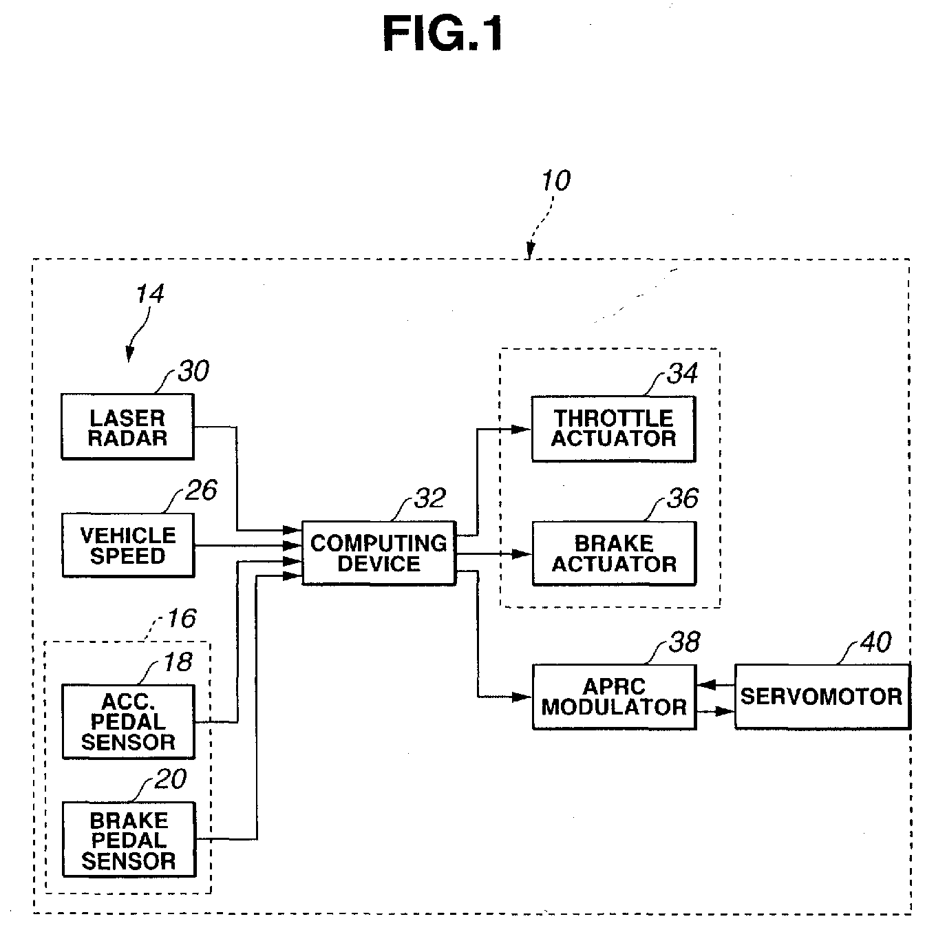
- the driver assisting system 10 comprises a data acquisition system (DAS) 14 arranged on the vehicle 12.
- DAS data acquisition system
- the DAS 14 includes sensing devices 16 for detecting driver operation.
- an accelerator pedal sensor 18 and a brake pedal sensor 20 are provided.
- the accelerator pedal sensor 18 generates a sensor signal indicative of information on accelerator application by the driver.
- the brake pedal sensor 20 generates a sensor signal indicative of in formation on brake pedal application by the driver.
- the accelerator pedal sensor 18 senses the depressed position of an accelerator or an accelerator pedal 22, and the brake pedal sensor 20 senses the depressed position of a brake pedal 24.
- the DAS 14 also includes a sensing device 26 for detecting vehicle motion.
- the sensing device is in the form of a vehicle speed sensor 26 that generates a sensor signal indicative of information on the vehicle speed.
- the DAS 14 also includes a sensing device 30 for detecting vehicle environment.
- the sensing device is in the form of laser radar 30 for detecting vehicle environment.
- the laser radar 30 is mounted to the vehicle 12 at a front bumper or a front grille thereof. It scans horizontally and laterally about 6 degrees to each side of an axis parallel to the vehicle longitudinal centerline, propagates infrared pulses forwardly and receives the reflected radiation by an obstacle, such as, a rear bumper of the preceding vehicle.
- the laser radar 30 can provide a sensor signal indicative of distance to and angular location of the obstacle.
- a computing device 32 which is coupled to the sensing devices 18, 20, 26 and 30, evaluates the detected driver operation, vehicle motion and vehicle environment.
- the evaluation includes determining relative speed Vr to the obstacle based on vehicle speed V from the vehicle speed sensor 26 and distance D from the laser radar 30.
- Vr and distance D the computing device 32 determines a degree with which the obstacle is coming close to the vehicle 12.
- the computing device 32 determines a desired value of deceleration accounting for the determined degree.
- the desired value of deceleration is used in a procedure that is carried out to prompt the driver to effecting a change in driver operation.
- the change in driver operation is in such a direction as to restrain an increase in the degree.
- the procedure includes applying braking torque to the vehicle 12 to subject the vehicle 12 to the determined value of deceleration.
- the computing device 32 is in the form of or includes a microprocessor based controller designed to carry out cruising control by providing commands to a throttle actuator 34 and a brake actuator 36.
- the computing device 32 is used to determine brake actuator command to the brake actuator 36, applying braking torque to road wheels of the vehicle 12 to subject the vehicle to the determined desired value of deceleration.
- Using the brake actuator 36 is only one example of applying braking torque. Another example is using engine braking or regenerative braking if an electric traction motor is used.
- the procedure includes applying reaction force at the accelerator pedal 24.
- the computing device 32 determines when to apply additional reaction force at accelerator pedal 22 to generate a trigger signal.
- the trigger signal is used as one input to another microprocessor based controller called an accelerator pedal reaction characteristic (APRC) modulator 38.
- the determined degree with which the obstacle is coming close to the vehicle 12 is used as another input to the APRC modulator 38.
- the information on accelerator pedal depressed position is used as other input to the APRC modulator 38. Such information is obtained from the accelerator pedal sensor 18.
- the APRC modulator 38 provides pattern of variation of reaction force with different depressed positions. Further description on this variation pattern of reaction force will be made later.
- the APRC modulator 38 determines a desired value of additional reaction force in response to the determined degree and provides accelerator pedal reaction force command to a servomotor 40.
- a link mechanism 42 operatively interconnects the servomotor 40 and the accelerator pedal 22.
- the servomotor 40 has embedded therein the accelerator pedal sensor 20.
- the accelerator pedal sensor 20 of this type measures an angle of depression of the accelerator pedal 22 in terms of a rotary angle through which the servomotor 40 is forced to turn.
- the accelerator pedal stroke sensor 22 provides its sensor signal to the APRC modulator 38.
- Figure 4A is an operation chart
- Figure 4B is a timing diagram. Both Figures 4A and 4B illustrate how the exemplary implementation of the present invention operates.
- the driver prior to moment t 1 , the driver keeps stepping on or depressing the accelerator pedal 22 and the degree 1/TTC with which the obstacle is coming close to the vehicle 12 rises.
- the driver steps on the accelerator pedal 22 and the degree 1/TTC is equal to or greater than a first predetermined degree 1/TTC A/PDL .
- a time period of 6 seconds is set as a value of time to collision TTC A/PDL .
- Applying additional reaction force begins with the moment t 1 immediately after the degree 1/TTC has exceeded the first predetermined degree 1/TTC A/PDL under the condition that the driver is depressing the accelerator pedal 22.
- the applying additional reaction force continues to prompt the driver to releasing the accelerator pedal 22 as long as the degree 1/TTC stays greater than a separate threshold degree R separate .
- the separate threshold degree R separate is less than the first predetermined degree 1/TTC A/PDL .
- the separate threshold degree R separate is zero.
- the driver releases the accelerator pedal 22 and the applying additional reaction force ends.
- the applying additional reaction force begins with the moment t 1 and continues until the driver subsequently releases the accelerator pedal 22 as long as the degree 1/TTC stays greater than or equal to the separate threshold degree R separate .
- the release of accelerator pedal 22 creates engine braking, applying braking torque, thus restraining an increase in the degree 1/TTC. This may be confirmed by the illustrated curve 50 in Figure 4B.
- the applying additional reaction force ends with the moment t 2 before the predetermined period of time T wait will expire at moment t 3 .
- the degree 1/TTC varies with time along the curve 50.
- the degree 1/TTC continues to stay greater than the separate threshold degree R separate until the degree 1/TTC drops down to the separate threshold degree R separate at moment t 4 without reaching another threshold degree 1/TTC DEC3 that is greater than 1/TTC A/PDL .
- the previous description on Figures 4A and 4B clearly indicates that the exemplary implementation carries out the procedure to prompt the driver to effecting the above-mentioned change in driver operation.
- the change is in such a direction as to restrain an increase in the degree 1/TTC.
- the procedure begins with the moment t 1 , and the predetermined condition is not met because the degree 1/TTC does not reach 1/TTC DEC3 .
- the driver steps on the accelerator pedal 22 and the degree 1/TTC is equal to or greater than the first predetermined degree 1/TTC A/PDL .
- Applying additional reaction force begins with the moment t 1 .
- the applying additional reaction force continues to prompt the driver to releasing the accelerator pedal 22 as long as the degree 1/TTC stays greater than the separate threshold degree R separate .
- the driver is still depressing the accelerator pedal 22 against the additional reaction force that continues to exist because the degree 1/TTC stays greater than or equal to the separate threshold degree R separate .
- the predetermined threshold degree 1/TTC DEC1 is equal to or slightly greater than the first-mentioned threshold degree 1/TTC A/PDL .
- the degree 1/TTC varies with time as shown by the curve 52 in Figure 5B, and the degree 1/TTC is greater than 1/TTC DEC1 at the moment t 3 , justifying the initiation of applying braking torque to the road wheels to subject the vehicle 12 to a desired value of deceleration.
- the desired value of deceleration is given by a first value ⁇ 1, which is selected from a set of values that satisfies the following relationship: ⁇ 1 ⁇ Vr 2 2D
- ⁇ 1 K Vr 2 2D
- K is a value falling in a range between 0 and 1.
- K is 0.8.
- a second value ⁇ 2 is used, instead of the first value ⁇ 1, as the desired value of deceleration.
- the increment ⁇ fix is 0.5 m/sec 2 .
- switching from ⁇ 1 to ⁇ 2 is provided to let the driver feel an increase in deceleration, which s/he would expect upon releasing the accelerator pedal 22.
- Applying braking torque continues as long as the degree 1/TTC stays greater than the separate threshold degree R separate and ends with moment t 6 when the driver depresses the brake pedal 24 to provide sufficient brake action that would produce braking torque high enough for application to the motor vehicle 12 instead of the braking torque being applied.
- the predetermined condition is met to start applying braking torque to the road wheels to subject the vehicle 12 to a desired value of deceleration.
- the desired value of deceleration is given by a third value ⁇ 3, which is selected from a set of values that satisfies the following relationship: ⁇ 3 ⁇ Vr 2 2D
- K is 0.8.
- Applying braking torque continues as long as the degree 1/TTC stays greater than the separate threshold degree R separate . It ends with the moment t 6 when the driver depresses the brake pedal 24 to provide sufficient brake action that would produce braking torque high enough for application to the motor vehicle 12 instead of the braking torque being applied.
- a value of time to collision TTC DEC3 is less than or equal to a value of time to collision TTC DEC1 .
- the degree 1/TTC reaches the threshold degree 1/TTC DEC3 at moment t 7 .
- the predetermined condition is met to start applying braking torque to the road wheels to subject the vehicle 12 to a desired value of deceleration that is given by the third value ⁇ 3.
- Applying braking torque continues as long as the degree 1/TTC stays greater than the separate threshold degree R separate . It ends with the moment t 6 when the driver depresses the brake pedal 24 to provide sufficient brake action that would produce braking torque high enough for application to the motor vehicle 12 instead of the braking torque being applied.
- the illustrated case in Figures 7A and 7B is different from the illustrated case in Figure 6A and 6B in that the driver has released the accelerator pedal 22 when the degree 1/TTC reaches the first threshold degree 1/TTC A/PDL (moment t 1 ).
- FIG. 8 and 9 illustrates a control routine 100 of the preferred implementation of the present invention. Turning on an ignition switch of the motor vehicle 12 initiates the execution of the control routine 100. The execution of the control routine 100 is repeated at regular interval of, for example, 50 milliseconds.
- programs for the control routine 100 are stored in computer readable storage media of the controller 32.
- the controller 32 inputs information of: distance D to an obstacle coming close to the motor vehicle 12, and vehicle speed V of the motor vehicle 12.
- the controller 32 next computes, at box 104, the degree 1/TTC with which the obstacle is coming close to the motor vehicle 12 by using the equation 1 (Eq. 1) and inputs, at box 106, driver operation.
- the controller 32 inputs information of: accelerator application and brake pedal application out of sensor signals of the accelerator pedal sensor 18 and the brake pedal sensor 20.
- the controller 32 determines whether or not the accelerator pedal 22 is depressed. The logic goes to box 110. At box 110, the controller 32 determines whether or not additional reaction force is being applied at the accelerator pedal 22. The logic goes to box 112. At box 112, the controller determines whether or not the degree 1/TTC is equal to or greater than the first threshold degree 1/TTC A/PDL . After box 112, the logic goes to an end point.
- the logic Upon or immediately after the moment t 1 ( Figure 4B), the logic goes down to box 112.
- the controller 32 determines that the degree 1/TTC is equal to or greater than the first threshold degree 1/TTC A/PDL .
- the logic goes to box 114.
- the controller 32 outputs a trigger signal that is used as one input to the APRC modulator 38, starting applying additional reaction force at the accelerator pedal 22.
- the controller 32 next records in a memory, at box 116, time as a start time T start . After box 116, the logic goes to the end point.
- an indication for example, a reaction force application flag, is set while the additional reaction force is being applied at the accelerator pedal 22.
- the logic goes down to box 110.
- the controller 32 determines that the additional reaction force is being applied at the accelerator pedal 22.
- the logic goes to box 118.
- the controller 32 compares elapsed time T from the recorded time T start to the predetermined period of time T wait .
- the controller 32 determines, at box 110, that T is less than T wait (T ⁇ T wait .
- the logic goes to box 120.
- the controller 32 determines whether or not the degree 1/TTC is equal to or less than the separate threshold degree R separate .
- the controller 32 determines, at box 120, that the degree 1/TTC is greater than the separate threshold degree R separate .
- the logic goes to the end point.
- the logic Upon or immediately after the moment t 2 , the logic goes down to box 108. As the accelerator pedal is released, the controller 32 determines, at box 108, that the accelerator pedal 22 is not depressed. The logic goes to box 122 in Figure 9. At box 122, the controller 32 determines whether or not the additional reaction force is being applied at the accelerator pedal 22. As the additional reaction force is being applied, the controller 32 outputs, at the next box 124, a trigger release signal to be applied to the APRC modulator 38, thus terminating applying additional reaction force at the accelerator pedal 22. The logic goes to box 126. At box 126, the controller 32 determines whether or not braking torque being applied to road wheels to subject the motor vehicle 12 to deceleration.
- the controller 32 determines, at the next box 128, whether or not the degree 1/TTC is equal to or greater than the threshold degree 1/TTC DEC3 . As readily seen from the curve 50 in Figure 4B, the controller 32 determines, at box 128, that the degree 1/TTC is less than 1/TTC DEC3 . After box 128, the logic goes to the end point.
- the controller 32 determines, at box 228, that the elapsed time T is equal to T wait .
- the logic goes to box 130.
- the controller 32 determines whether or not the degree 1/TTC is equal to or greater than the threshold degree 1/TTC DEC1 .
- the controller 32 determines, at box 130, that the degree 1/TTC is greater than the threshold degree 1/TTC DEC1 .
- the logic goes to box 132.
- the controller 32 computes the first value ⁇ 1.
- the controller 32 outputs, at the next box 134, a brake actuator command, causing the brake actuator 36 to start applying brake torque to road wheels to subject the motor vehicle 12 to the desired value of deceleration given by the first value ⁇ 1. After box 134, the logic goes to the end point.
- the controller 32 determines, at box 118, that the elapsed time T is greater than T wait .
- the logic goes to box 136.
- the controller 32 determines whether or not the degree 1/TTC is equal to or less than the separate threshold degree R separate .
- the controller 32 determines, at box 136, that the degree 1/TTC is greater than the separate threshold degree R separate .
- the logic goes to the end point.
- the logic flows along boxes 102, 104, 106, 108, 122 and 124 and goes to box 126.
- the controller 32 determines, at box 126, that the braking torque is being applied.
- the logic goes to box 138.
- the controller 32 determines whether or not braking torque is being applied for the desired value of vehicle deceleration ⁇ 1. Since this is the case, the logic goes to box 140.
- the controller 32 computes the second value ⁇ 2.
- the controller 32 outputs, at the next box 142, a brake actuator command, causing the brake actuator 36 to start applying brake torque to road wheels to subject the motor vehicle 12 to the desired value of deceleration given by the second value ⁇ 2.
- the logic goes to the end point.
- the logic goes down to box 138. Since the braking torque application for the desired value vehicle deceleration ⁇ 2 has begun, the controller 32 determines, at box 138, that braking torque is not applied for the desired value of vehicle deceleration ⁇ 1. The logic goes to box 144. At box 144, the controller 32 determines whether or not the degree 1/TTC is equal to or less than the separate threshold degree R separate . As readily seen from the curve 52 in Figure 5B, the controller 32 determines, at box 144, that the degree 1/TTC is greater than the separate threshold degree R separate . The logic goes to box 146.
- the controller 32 determines whether or not the brake action predicted by the depressed position of brake pedal 24 is sufficient. This may be simply determined by comparing the detected depressed position of the brake pedal 24 to a threshold depressed position. Since the brake pedal 24 is not depressed, the logic goes to the end point after box 146.
- the controller 32 determines, at box 146, that the predicted brake action is sufficient. The logic goes to box 148. At box 148, the controller 32 outputs a signal, causing the brake actuator 36 to terminate applying braking torque. After box 148, the logic goes to the end point.
- the controller 32 determines, at box 128, that the degree 1/TTC is equal to or greater than 1/TTC DEC3 .
- the logic goes to box 150.
- the controller 32 computes the third value ⁇ 3.
- the controller 32 outputs, at the next box 152, a brake actuator command, causing the brake actuator 36 to start applying brake torque to road wheels to subject the motor vehicle 12 to the desired value of deceleration given by the third value ⁇ 3.
- the logic goes to the end point.
- the logic goes down to box 138. Since the braking torque application for the desired value vehicle deceleration ⁇ 3 has begun, the controller 32 determines, at box 138, that braking torque is not applied for the desired value of vehicle deceleration ⁇ 1. The logic goes to box 144. As readily seen from the curve 54 in Figure 6B, the controller 32 determines, at box 144, that the degree 1/TTC is greater than the separate threshold degree R separate . The logic goes to box 146. At box 146, the controller 32 determines that the brake action predicted by the depressed position of brake pedal 24 is insufficient because the brake pedal 24 is not depressed. The logic goes to the end point after box 146.
- the controller 32 determines, at box 146, that the predicted brake action is sufficient. The logic goes to box 148. At box 148, the controller 32 outputs a signal, causing the brake actuator 36 to terminate applying braking torque. After box 148, the logic goes to the end point.
- the controller 32 determines, at box 128, that the degree 1/TTC is equal to or greater than 1/TTC DEC3 .
- the logic goes to box 150.
- the controller 32 computes the third value ⁇ 3.
- the controller 32 outputs, at the next box 152, a brake actuator command, causing the brake actuator 36 to start applying brake torque to road wheels to subject the motor vehicle 12 to the desired value of deceleration given by the third value ⁇ 3.
- the logic goes to the end point.
- the controller 32 If, at box 120, it determines that the degree 1/TTC is equal to or less than R separate , the controller 32 outputs, at the next box 154, a trigger release signal to be applied to the APRC modulator 38, thus terminating applying additional reaction force at the accelerator pedal 22. After box 154, the logic goes to the end point.
- the controller 32 If, at box 136, it determines that the degree 1/TTC is equal to or less than R separate , the controller 32 outputs, at the next box 156, a trigger release signal to be applied to the APRC modulator 38, thus terminating applying additional reaction force at the accelerator pedal 22. At the next box 158, the controller 32 outputs a signal, causing the brake actuator 36 to terminate applying braking torque. After box 158, the logic goes to the end point.
- the controller 32 If, at box 144, it determines that the degree 1/TTC is equal to or less than R separate , the controller 32 outputs, at box 148, a signal, causing the brake actuator 36 to terminate applying braking torque. After box 148, the logic goes to the end point.
- the exemplary implementation of the present invention provides a driver assisting system or method for a motor vehicle.
- Driver operation, vehicle motion and vehicle environment are detected.
- the detected driver operation, vehicle motion and vehicle environment are evaluated.
- the driver is prompted to effecting a change in driver operation by applying braking torque to the motor vehicle and/or additional reaction force at the accelerator.
- the change in driver operation is in such a direction as to restrain an increase in degree with which the obstacle is coming close to the motor vehicle.
Landscapes
- Engineering & Computer Science (AREA)
- Transportation (AREA)
- Mechanical Engineering (AREA)
- Automation & Control Theory (AREA)
- Human Computer Interaction (AREA)
- Chemical & Material Sciences (AREA)
- Combustion & Propulsion (AREA)
- Regulating Braking Force (AREA)
- Electric Propulsion And Braking For Vehicles (AREA)
- Control Of Driving Devices And Active Controlling Of Vehicle (AREA)
- Controls For Constant Speed Travelling (AREA)
- Control Of Vehicle Engines Or Engines For Specific Uses (AREA)
Abstract
Description
- The present invention relates generally to motor vehicles, and more particularly to method and system for assisting a driver of a motor vehicle.
- Various driver assisting systems of the above kind are known. One example is disclosed in JP-A 8-34326, which fully brakes a motor vehicle independent of a driver of the vehicle upon determination of emergency out of manipulation of a brake pedal and a steering wheel upon or immediately after determination of potential hazard out of the range between the vehicle and an obstacle and the time rate at which the range was changing. This automatic brake is intended to assist brake torque needed in such emergency atmosphere. Another example is disclosed in JP P2001-90831A, which decelerates a motor vehicle independent of a driver of the vehicle by shifting down an automatic transmission upon or immediately after determination that deceleration of the vehicle is required. The information from a navigation unit and the range between the vehicle and an obstacle determine the need for such deceleration.
- The above-mentioned driver assisting systems are common in changing the operation of a motor vehicle independent of a driver of the vehicle. The action required to change the vehicle operation is intrusive. Conditions where that action is required should therefore be avoided or minimized.
- Accordingly, a need remains for method and system for assisting a driver that prompt a driver of a motor vehicle to effecting deceleration of the vehicle in compatible manner with the reaction of the driver.
- An object of the present invention is to provide a vehicle driver assisting method and system that prompt a driver of a motor vehicle to effecting deceleration of the vehicle in compatible manner with the reaction of the driver.
- The present invention provides, in one aspect thereof, a system for assisting a driver of a motor vehicle, comprising:
- a plurality of sensing devices for detecting driver operation, vehicle motion and vehicle environment, the vehicle environment including an obstacle in a field around the motor vehicle;
- a computing device coupled to the plurality of sensing devices for determining a degree with which the obstacle is coming close to the motor vehicle to determine a desired value of deceleration accounting for the determined degree; and
- a vehicle control application for carrying out a procedure to prompt the driver to effecting a change in driver operation, which change is in such a direction as to restrain an increase in the degree, the procedure including applying braking torque to the motor vehicle to subject the motor vehicle to the desired value of deceleration.
-
- According to another aspect of the present invention, there is provided a method for assisting a driver of a motor vehicle having an accelerator, comprising:
- detecting, on a substantially real-time basis, driver operation, vehicle motion and vehicle environment, the vehicle environment including an obstacle in a field around the motor vehicle;
- evaluating the detected driver operation, vehicle motion and vehicle environment; and
- prompting, based on the evaluation, the driver to effecting a change in driver operation by applying at least one of braking torque to the motor vehicle and additional reaction force at the accelerator, which change is in such a direction as to restrain an increase in degree with which the obstacle is coming close to the motor vehicle.
-
- The present invention will be apparent from reading of the following description in conjunction with the accompanying drawings.
- Figure 1 is a control diagram showing control of one exemplary implementation of method and system for assisting a driver of a motor vehicle according to the present invention.
- Figure 2 is a view illustrating how hardware of the implementation in Figure 1 is arranged on a motor vehicle.
- Figure 3 is a schematic view of a servomotor of an accelerator reaction characteristic modulation actuator in operative relationship with an accelerator pedal.
- Figure 4A is an operation chart, and Figure 4B is a timing diagram, both of which illustrate how the exemplary implementation of the present invention operates in one case (case 1).
- Figure 5A is an operation chart, and Figure 5B is a timing diagram, both of which illustrate how the exemplary implementation of the present invention operates in another case (case 2).
- Figure 6A is an operation chart, and Figure 6B is a timing diagram, both of which illustrate how the exemplary implementation of the present invention operates in another case (case 3).
- Figure 7A is an operation chart, and Figure 7B is a timing diagram, both of which illustrate how the exemplary implementation of the present invention operates in another case (case 4).
- Figures 8 and 9 illustrate a flow diagram of a control routine implementing the present invention.
-
- Referring now in detail to an exemplary implementation of the present invention, a system and
method 10 for assisting a driver of amotor vehicle 12 is disclosed as shown in Figures 1 and 2. Driver operation, vehicle motion and vehicle environment are detected. The detected driver operation, vehicle motion and vehicle environment are evaluated. Based on the evaluation, the driver is prompted to effecting a change in driver operation by applying at least one of braking torque to the motor vehicle and additional reaction force at the accelerator. The change in driver operation is in such a direction as to restrain an increase in degree with which the obstacle is coming close to the motor vehicle. - Detecting driver operation, vehicle motion and vehicle environment includes obtaining information indicated by a plurality of signals that include accelerator application, brake pedal application, vehicle speed, distance to the obstacle and relative speed to the obstacle. The
driver assisting system 10 comprises a data acquisition system (DAS) 14 arranged on thevehicle 12. - As shown in Figure 1, the
DAS 14 includessensing devices 16 for detecting driver operation. In this example, anaccelerator pedal sensor 18 and abrake pedal sensor 20 are provided. Theaccelerator pedal sensor 18 generates a sensor signal indicative of information on accelerator application by the driver. Thebrake pedal sensor 20 generates a sensor signal indicative of in formation on brake pedal application by the driver. As shown in Figure 2, theaccelerator pedal sensor 18 senses the depressed position of an accelerator or anaccelerator pedal 22, and thebrake pedal sensor 20 senses the depressed position of a brake pedal 24. - The
DAS 14 also includes asensing device 26 for detecting vehicle motion. The sensing device is in the form of avehicle speed sensor 26 that generates a sensor signal indicative of information on the vehicle speed. TheDAS 14 also includes asensing device 30 for detecting vehicle environment. The sensing device is in the form oflaser radar 30 for detecting vehicle environment. - As shown in Figure 2, the
laser radar 30 is mounted to thevehicle 12 at a front bumper or a front grille thereof. It scans horizontally and laterally about 6 degrees to each side of an axis parallel to the vehicle longitudinal centerline, propagates infrared pulses forwardly and receives the reflected radiation by an obstacle, such as, a rear bumper of the preceding vehicle. Thelaser radar 30 can provide a sensor signal indicative of distance to and angular location of the obstacle. - A
computing device 32, which is coupled to thesensing devices vehicle speed sensor 26 and distance D from thelaser radar 30. Using relative speed Vr and distance D, thecomputing device 32 determines a degree with which the obstacle is coming close to thevehicle 12. In this embodiment, the degree is the reciprocal of time to collision (TTC) and expressed as:computing device 32 determines a desired value of deceleration accounting for the determined degree. The desired value of deceleration is used in a procedure that is carried out to prompt the driver to effecting a change in driver operation. The change in driver operation is in such a direction as to restrain an increase in the degree. The procedure includes applying braking torque to thevehicle 12 to subject thevehicle 12 to the determined value of deceleration. - In the exemplary implementation, the
computing device 32 is in the form of or includes a microprocessor based controller designed to carry out cruising control by providing commands to athrottle actuator 34 and abrake actuator 36. In the exemplary implementation of the present invention, thecomputing device 32 is used to determine brake actuator command to thebrake actuator 36, applying braking torque to road wheels of thevehicle 12 to subject the vehicle to the determined desired value of deceleration. Using thebrake actuator 36 is only one example of applying braking torque. Another example is using engine braking or regenerative braking if an electric traction motor is used. - In the exemplary implementation of the present invention, the procedure includes applying reaction force at the accelerator pedal 24. The
computing device 32 determines when to apply additional reaction force ataccelerator pedal 22 to generate a trigger signal. The trigger signal is used as one input to another microprocessor based controller called an accelerator pedal reaction characteristic (APRC)modulator 38. The determined degree with which the obstacle is coming close to thevehicle 12 is used as another input to theAPRC modulator 38. The information on accelerator pedal depressed position is used as other input to theAPRC modulator 38. Such information is obtained from theaccelerator pedal sensor 18. TheAPRC modulator 38 provides pattern of variation of reaction force with different depressed positions. Further description on this variation pattern of reaction force will be made later. TheAPRC modulator 38 determines a desired value of additional reaction force in response to the determined degree and provides accelerator pedal reaction force command to aservomotor 40. - As shown in Figure 3, a
link mechanism 42 operatively interconnects theservomotor 40 and theaccelerator pedal 22. In the embodiment, theservomotor 40 has embedded therein theaccelerator pedal sensor 20. Theaccelerator pedal sensor 20 of this type measures an angle of depression of theaccelerator pedal 22 in terms of a rotary angle through which theservomotor 40 is forced to turn. The acceleratorpedal stroke sensor 22 provides its sensor signal to theAPRC modulator 38. For further information on applying additional reaction force at the accelerator pedal, reference should be made to the co-pending commonly assigned United States patent application No. unassigned yet, entitled "Driving Assist System and Method with Accelerator Pedal Reaction Force Control" claiming the priority of Japanese Patent Application No. 2002-003803, filed January 10, 2002, which United States patent application has been hereby incorporated by reference in its entirety. - Figure 4A is an operation chart, and Figure 4B is a timing diagram. Both Figures 4A and 4B illustrate how the exemplary implementation of the present invention operates. In Figure 4B, prior to moment t1, the driver keeps stepping on or depressing the
accelerator pedal 22 and thedegree 1/TTC with which the obstacle is coming close to thevehicle 12 rises. - At the moment t1, the driver steps on the
accelerator pedal 22 and thedegree 1/TTC is equal to or greater than a firstpredetermined degree 1/TTCA/PDL. In the exemplary implementation, a time period of 6 seconds is set as a value of time to collision TTCA/PDL. Applying additional reaction force begins with the moment t1 immediately after thedegree 1/TTC has exceeded the firstpredetermined degree 1/TTCA/PDL under the condition that the driver is depressing theaccelerator pedal 22. After the moment t1, the applying additional reaction force continues to prompt the driver to releasing theaccelerator pedal 22 as long as thedegree 1/TTC stays greater than a separate threshold degree Rseparate. The separate threshold degree Rseparate is less than the firstpredetermined degree 1/TTCA/PDL. In the exemplary implementation, the separate threshold degree Rseparate is zero. - Subsequently, at moment t2 before expiration of a predetermined period of time Twait, the driver releases the
accelerator pedal 22 and the applying additional reaction force ends. The applying additional reaction force begins with the moment t1 and continues until the driver subsequently releases theaccelerator pedal 22 as long as thedegree 1/TTC stays greater than or equal to the separate threshold degree Rseparate. The release ofaccelerator pedal 22 creates engine braking, applying braking torque, thus restraining an increase in thedegree 1/TTC. This may be confirmed by the illustratedcurve 50 in Figure 4B. - In the illustrated case, the applying additional reaction force ends with the moment t2 before the predetermined period of time Twait will expire at moment t3. After the driver has released the accelerator pedal 22 (moment t2), the
degree 1/TTC varies with time along thecurve 50. As thecurve 50 clearly shows, thedegree 1/TTC continues to stay greater than the separate threshold degree Rseparate until thedegree 1/TTC drops down to the separate threshold degree Rseparate at moment t4 without reaching anotherthreshold degree 1/TTCDEC3 that is greater than 1/TTCA/PDL. The previous description on Figures 4A and 4B clearly indicates that the exemplary implementation carries out the procedure to prompt the driver to effecting the above-mentioned change in driver operation. The change is in such a direction as to restrain an increase in thedegree 1/TTC. As may be clarified later, there is predetermined condition to be met before applying braking torque to the motor vehicle to subject the motor vehicle to the desired value of deceleration. In the illustrated case in Figures 4A and 4B, the procedure begins with the moment t1, and the predetermined condition is not met because thedegree 1/TTC does not reach 1/TTCDEC3. - Referring next to Figures 5A and 5B, the operation of exemplary implementation of the present invention is described. In Figure 5B, prior to moment t1, the driver keeps stepping on or depressing the
accelerator pedal 22 and thedegree 1/TTC with which the obstacle is coming close to thevehicle 12 rises. - At the moment t1, the driver steps on the
accelerator pedal 22 and thedegree 1/TTC is equal to or greater than the firstpredetermined degree 1/TTCA/PDL. Applying additional reaction force begins with the moment t1. After the moment t1, the applying additional reaction force continues to prompt the driver to releasing theaccelerator pedal 22 as long as thedegree 1/TTC stays greater than the separate threshold degree Rseparate. - Subsequently, at the moment t3 upon expiration of the predetermined period of time Twait, the driver is still depressing the
accelerator pedal 22 against the additional reaction force that continues to exist because thedegree 1/TTC stays greater than or equal to the separate threshold degree Rseparate. At this moment t3, it is determined whether or not applying braking torque is justified. Specifically, it is determined whether or not thedegree 1/TTC is greater than or equal to anotherpredetermined threshold degree 1/TTCDEC1. In the exemplary implementation, thepredetermined threshold degree 1/TTCDEC1 is equal to or slightly greater than the first-mentionedthreshold degree 1/TTCA/PDL. In the illustrated case, thedegree 1/TTC varies with time as shown by thecurve 52 in Figure 5B, and thedegree 1/TTC is greater than 1/TTCDEC1 at the moment t3, justifying the initiation of applying braking torque to the road wheels to subject thevehicle 12 to a desired value of deceleration. From the moment t3 to moment t5 when the driver releases theaccelerator pedal 22 subsequently, the desired value of deceleration is given by a first value α1, which is selected from a set of values that satisfies the following relationship:motor vehicle 12 to the value of deceleration equal to or greater than Vr2/2D would bring the relative speed Vr to zero on or before the distance D becoming zero. In the exemplary implementation of the present invention, the first value α1 is expressed as,
In the exemplary implementation, K is 0.8. - Immediately after the moment t5, applying braking torque continues. But, a second value α2 is used, instead of the first value α1, as the desired value of deceleration. The second value α2 is expressed as,
In the exemplary implementation, the increment αfix is 0.5 m/sec2. In the exemplary implementation, switching from α1 to α2 is provided to let the driver feel an increase in deceleration, which s/he would expect upon releasing theaccelerator pedal 22. - Applying braking torque continues as long as the
degree 1/TTC stays greater than the separate threshold degree Rseparate and ends with moment t6 when the driver depresses the brake pedal 24 to provide sufficient brake action that would produce braking torque high enough for application to themotor vehicle 12 instead of the braking torque being applied. - Referring now to Figures 6A and 6B, the operation of exemplary implementation of the present invention is described. This illustrated case is substantially the same as the before described case illustrated in Figures 4A and 4B till the moment t3. However, varying of the
degree 1/TTC after the moment t2 differs. As indicated by the illustratedcurve 50, according to the illustrated case in Figures 4A and 4B, thedegree 1/TTC does not reach thethreshold degree 1/TTCDEC3 that is greater than 1/TTCDEC1. According to the illustrated case in Figures 6A and 6B, thecurve 54 clearly indicates that thedegree 1/TTC reaches thethreshold degree 1/TTCDEC3 at moment t7. At the moment t7, the predetermined condition is met to start applying braking torque to the road wheels to subject thevehicle 12 to a desired value of deceleration. The desired value of deceleration is given by a third value α3, which is selected from a set of values that satisfies the following relationship:
In the exemplary implementation, K is 0.8. - Applying braking torque continues as long as the
degree 1/TTC stays greater than the separate threshold degree Rseparate. It ends with the moment t6 when the driver depresses the brake pedal 24 to provide sufficient brake action that would produce braking torque high enough for application to themotor vehicle 12 instead of the braking torque being applied. - With regard to the
threshold degrees 1/TTCDEC1 (see Figure 5B) and 1/TTCDEC3 (see Figure 6B), a value of time to collision TTCDEC3 is less than or equal to a value of time to collision TTCDEC1. - Referring now to Figures 7A and 7B, the operation of exemplary implementation of the present invention is described. This illustrated case is substantially the same as the above described case illustrated in Figures 6A and 6B in that the
degree 1/TTC reaches after driver releasing theaccelerator pedal 22. - As shown by the illustrated
curve 56 in Figure 7B, thedegree 1/TTC reaches thethreshold degree 1/TTCDEC3 at moment t7. At the moment t7, the predetermined condition is met to start applying braking torque to the road wheels to subject thevehicle 12 to a desired value of deceleration that is given by the third value α3. Applying braking torque continues as long as thedegree 1/TTC stays greater than the separate threshold degree Rseparate. It ends with the moment t6 when the driver depresses the brake pedal 24 to provide sufficient brake action that would produce braking torque high enough for application to themotor vehicle 12 instead of the braking torque being applied. - The illustrated case in Figures 7A and 7B is different from the illustrated case in Figure 6A and 6B in that the driver has released the
accelerator pedal 22 when thedegree 1/TTC reaches thefirst threshold degree 1/TTCA/PDL (moment t1). - The flow diagram in Figures 8 and 9 illustrates a
control routine 100 of the preferred implementation of the present invention. Turning on an ignition switch of themotor vehicle 12 initiates the execution of thecontrol routine 100. The execution of thecontrol routine 100 is repeated at regular interval of, for example, 50 milliseconds. In the implementation, programs for thecontrol routine 100 are stored in computer readable storage media of thecontroller 32. - In Figure 8, at
input box 102, thecontroller 32 inputs information of: distance D to an obstacle coming close to themotor vehicle 12, and vehicle speed V of themotor vehicle 12. Thecontroller 32 next computes, atbox 104, thedegree 1/TTC with which the obstacle is coming close to themotor vehicle 12 by using the equation 1 (Eq. 1) and inputs, atbox 106, driver operation. Atbox 106, thecontroller 32 inputs information of: accelerator application and brake pedal application out of sensor signals of theaccelerator pedal sensor 18 and thebrake pedal sensor 20. - In the illustrated
case 1 in Figures 4A and 4B, prior to the moment t1, theaccelerator pedal 22 is depressed, thedegree 1/TTC is less than thefirst threshold degree 1/TTCA/PDL, and no additional reaction force is applied at theaccelerator pedal 22. Atbox 108, thecontroller 32 determines whether or not theaccelerator pedal 22 is depressed. The logic goes tobox 110. Atbox 110, thecontroller 32 determines whether or not additional reaction force is being applied at theaccelerator pedal 22. The logic goes tobox 112. Atbox 112, the controller determines whether or not thedegree 1/TTC is equal to or greater than thefirst threshold degree 1/TTCA/PDL. Afterbox 112, the logic goes to an end point. - Upon or immediately after the moment t1 (Figure 4B), the logic goes down to
box 112. Atbox 112, thecontroller 32 determines that thedegree 1/TTC is equal to or greater than thefirst threshold degree 1/TTCA/PDL. The logic goes tobox 114. Thecontroller 32 outputs a trigger signal that is used as one input to theAPRC modulator 38, starting applying additional reaction force at theaccelerator pedal 22. Thecontroller 32 next records in a memory, atbox 116, time as a start time Tstart. Afterbox 116, the logic goes to the end point. Although not positively shown in the flow diagram, an indication, for example, a reaction force application flag, is set while the additional reaction force is being applied at theaccelerator pedal 22. - During period between the moment t1 and t2 (Figure 4B), the logic goes down to
box 110. Atbox 110, thecontroller 32 determines that the additional reaction force is being applied at theaccelerator pedal 22. The logic goes tobox 118. Atbox 118, thecontroller 32 compares elapsed time T from the recorded time Tstart to the predetermined period of time Twait. Thecontroller 32 determines, atbox 110, that T is less than Twait (T < Twait. The logic goes tobox 120. Atbox 120, thecontroller 32 determines whether or not thedegree 1/TTC is equal to or less than the separate threshold degree Rseparate. As readily seen from thecurve 50 in Figure 4B, thecontroller 32 determines, atbox 120, that thedegree 1/TTC is greater than the separate threshold degree Rseparate. Afterbox 120, the logic goes to the end point. - Upon or immediately after the moment t2, the logic goes down to
box 108. As the accelerator pedal is released, thecontroller 32 determines, atbox 108, that theaccelerator pedal 22 is not depressed. The logic goes tobox 122 in Figure 9. Atbox 122, thecontroller 32 determines whether or not the additional reaction force is being applied at theaccelerator pedal 22. As the additional reaction force is being applied, thecontroller 32 outputs, at thenext box 124, a trigger release signal to be applied to theAPRC modulator 38, thus terminating applying additional reaction force at theaccelerator pedal 22. The logic goes tobox 126. Atbox 126, thecontroller 32 determines whether or not braking torque being applied to road wheels to subject themotor vehicle 12 to deceleration. As no braking torque is applied via thebrake actuator 36, thecontroller 32 determines, at thenext box 128, whether or not thedegree 1/TTC is equal to or greater than thethreshold degree 1/TTCDEC3. As readily seen from thecurve 50 in Figure 4B, thecontroller 32 determines, atbox 128, that thedegree 1/TTC is less than 1/TTCDEC3. Afterbox 128, the logic goes to the end point. - Subsequently after the moment t2, the logic flows along
box 122,box 126, andbox 128 down to the end point. - In the illustrated case 2 in Figures 5A and 5B, upon or immediately after the moment t3, the
controller 32 determines, at box 228, that the elapsed time T is equal to Twait. The logic goes tobox 130. Atbox 130, thecontroller 32 determines whether or not thedegree 1/TTC is equal to or greater than thethreshold degree 1/TTCDEC1. As readily seen from the illustratedcurve 52 in Figure 5B, thecontroller 32 determines, atbox 130, that thedegree 1/TTC is greater than thethreshold degree 1/TTCDEC1. The logic goes tobox 132. Atbox 132, thecontroller 32 computes the first value α1. Thecontroller 32 outputs, at thenext box 134, a brake actuator command, causing thebrake actuator 36 to start applying brake torque to road wheels to subject themotor vehicle 12 to the desired value of deceleration given by the first value α1. Afterbox 134, the logic goes to the end point. - Subsequently, as the elapsed time T exceeds Twait, the
controller 32 determines, atbox 118, that the elapsed time T is greater than Twait. The logic goes tobox 136. Atbox 136, thecontroller 32 determines whether or not thedegree 1/TTC is equal to or less than the separate threshold degree Rseparate. As readily seen from thecurve 52 in Figure 5B, thecontroller 32 determines, atbox 136, that thedegree 1/TTC is greater than the separate threshold degree Rseparate. Afterbox 136, the logic goes to the end point. - Upon or immediately after the moment t5, the logic flows along
boxes box 126. Thecontroller 32 determines, atbox 126, that the braking torque is being applied. The logic goes tobox 138. Atbox 138, thecontroller 32 determines whether or not braking torque is being applied for the desired value of vehicle deceleration α1. Since this is the case, the logic goes tobox 140. Atbox 140, thecontroller 32 computes the second value α2. Thecontroller 32 outputs, at thenext box 142, a brake actuator command, causing thebrake actuator 36 to start applying brake torque to road wheels to subject themotor vehicle 12 to the desired value of deceleration given by the second value α2. Afterbox 142, the logic goes to the end point. - During period between the moment t5 and t6 (Figure 5B), the logic goes down to
box 138. Since the braking torque application for the desired value vehicle deceleration α2 has begun, thecontroller 32 determines, atbox 138, that braking torque is not applied for the desired value of vehicle deceleration α1. The logic goes tobox 144. Atbox 144, thecontroller 32 determines whether or not thedegree 1/TTC is equal to or less than the separate threshold degree Rseparate. As readily seen from thecurve 52 in Figure 5B, thecontroller 32 determines, atbox 144, that thedegree 1/TTC is greater than the separate threshold degree Rseparate. The logic goes tobox 146. Atbox 146, thecontroller 32 determines whether or not the brake action predicted by the depressed position of brake pedal 24 is sufficient. This may be simply determined by comparing the detected depressed position of the brake pedal 24 to a threshold depressed position. Since the brake pedal 24 is not depressed, the logic goes to the end point afterbox 146. - Upon or immediately after the moment t6 (Figure 5B), the
controller 32 determines, atbox 146, that the predicted brake action is sufficient. The logic goes tobox 148. Atbox 148, thecontroller 32 outputs a signal, causing thebrake actuator 36 to terminate applying braking torque. Afterbox 148, the logic goes to the end point. - In the illustrated case 3 in Figure 6A and 6B, upon or immediately after moment t7, the
controller 32, determines, atbox 128, that thedegree 1/TTC is equal to or greater than 1/TTCDEC3. The logic goes tobox 150. Atbox 150, thecontroller 32 computes the third value α3. Thecontroller 32 outputs, at thenext box 152, a brake actuator command, causing thebrake actuator 36 to start applying brake torque to road wheels to subject themotor vehicle 12 to the desired value of deceleration given by the third value α3. Afterbox 152, the logic goes to the end point. - During period between the moment t7 and t6 (Figure 6B), the logic goes down to
box 138. Since the braking torque application for the desired value vehicle deceleration α3 has begun, thecontroller 32 determines, atbox 138, that braking torque is not applied for the desired value of vehicle deceleration α1. The logic goes tobox 144. As readily seen from thecurve 54 in Figure 6B, thecontroller 32 determines, atbox 144, that thedegree 1/TTC is greater than the separate threshold degree Rseparate. The logic goes tobox 146. Atbox 146, thecontroller 32 determines that the brake action predicted by the depressed position of brake pedal 24 is insufficient because the brake pedal 24 is not depressed. The logic goes to the end point afterbox 146. - Upon or immediately after the moment t6 (Figure 6B), the
controller 32 determines, atbox 146, that the predicted brake action is sufficient. The logic goes tobox 148. Atbox 148, thecontroller 32 outputs a signal, causing thebrake actuator 36 to terminate applying braking torque. Afterbox 148, the logic goes to the end point. - In the illustrated case 4 in Figures 7A and 7B, since the
accelerator pedal 22 is not depressed, the logic always flow alongboxes - Upon or immediately after the moment t7 (Figure 7B), the
controller 32 determines, atbox 128, that thedegree 1/TTC is equal to or greater than 1/TTCDEC3. The logic goes tobox 150. Atbox 150, thecontroller 32 computes the third value α3. Thecontroller 32 outputs, at thenext box 152, a brake actuator command, causing thebrake actuator 36 to start applying brake torque to road wheels to subject themotor vehicle 12 to the desired value of deceleration given by the third value α3. Afterbox 152, the logic goes to the end point. - The operation after the moment t7 in Figure 7B is the same as the operation in Figure 6B.
- The procedure mentioned above is immediately terminated when the
degree 1/TTC drops down to or below the separate threshold degree Rseparate. - If, at
box 120, it determines that thedegree 1/TTC is equal to or less than Rseparate, thecontroller 32 outputs, at thenext box 154, a trigger release signal to be applied to theAPRC modulator 38, thus terminating applying additional reaction force at theaccelerator pedal 22. Afterbox 154, the logic goes to the end point. - If, at
box 136, it determines that thedegree 1/TTC is equal to or less than Rseparate, thecontroller 32 outputs, at thenext box 156, a trigger release signal to be applied to theAPRC modulator 38, thus terminating applying additional reaction force at theaccelerator pedal 22. At thenext box 158, thecontroller 32 outputs a signal, causing thebrake actuator 36 to terminate applying braking torque. Afterbox 158, the logic goes to the end point. - If, at
box 144, it determines that thedegree 1/TTC is equal to or less than Rseparate, thecontroller 32 outputs, atbox 148, a signal, causing thebrake actuator 36 to terminate applying braking torque. Afterbox 148, the logic goes to the end point. - From the preceding description, it will be appreciated that the exemplary implementation of the present invention provides a driver assisting system or method for a motor vehicle. Driver operation, vehicle motion and vehicle environment are detected. The detected driver operation, vehicle motion and vehicle environment are evaluated. Based on the evaluation, the driver is prompted to effecting a change in driver operation by applying braking torque to the motor vehicle and/or additional reaction force at the accelerator. The change in driver operation is in such a direction as to restrain an increase in degree with which the obstacle is coming close to the motor vehicle.
- While the present invention has been particularly described, in conjunction with various implementations of the present invention, it is evident that many alternatives, modifications and variations will be apparent to those skilled in the art in light of the foregoing description. It is therefore contemplated that the appended claims will embrace any such alternatives, modifications and variations as falling within the true scope and spirit of the present invention.
- This application claims the priority of Japanese Patent Application No. 2002-073878, filed March 18, 2002, the disclosure of which is hereby incorporated by reference in its entirety.
Claims (23)
- A system for assisting a driver of a motor vehicle, comprising:a plurality of sensing devices for detecting driver operation, vehicle motion and vehicle environment, the vehicle environment including an obstacle in a field around the motor vehicle;a computing device coupled to the plurality of sensing devices for determining a degree with which the obstacle is coming close to the motor vehicle to determine a desired value of deceleration accounting for the determined degree; anda vehicle control application for carrying out a procedure to prompt the driver to effecting a change in driver operation, which change is in such a direction as to restrain an increase in the degree, the procedure including applying braking torque to the motor vehicle to subject the motor vehicle to the desired value of deceleration.
- The system as claimed in claim 1, wherein the procedure includes altering reaction force at an accelerator pedal based on the degree.
- The system as claimed in claim 1 or 2, wherein the procedure begins with first moment immediately after the degree has exceeded a threshold degree when the driver is depressing an accelerator pedal.
- The system as claimed in claim 1 or 2, wherein the computing device determines, as the desired value of deceleration, a first value based on distance to and relative speed to the obstacle and wherein the computing device determines, as the desired value of deceleration, a second value by correcting the first value when the driver releases the accelerator pedal after beginning of the procedure.
- The system as claimed in claim 4, wherein the correcting the first value is in the form of adding an increment to the first value.
- The system as claimed in claim 1 or 2, wherein the computing device determines, as the desired value of deceleration, a value of deceleration based on distance to and relative speed to the obstacle and keeps the determined value unaltered after the procedure has begun.
- The system as claimed in claim 1 or 2, wherein the applying braking torque ends with moment when the driver depresses a brake pedal.
- The system as claimed in claim 1 or 2, wherein the computing device predicts deceleration due to brake action from a depressed angle of a brake pedal; and
wherein the applying braking torque ends with moment when the predicted deceleration exceeds the desired value of deceleration. - The system as claimed in claim 1 or 2, wherein the applying braking torque ends with moment when the degree drops below a separate threshold degree.
- The system as claimed in claim 2, wherein the applying braking torque begins with moment when the driver keeps depressing the accelerator pedal as opposed to the altered reaction force beyond a predetermined period of time.
- The system as claimed in claim 10, wherein the altering reaction force is in the form of applying additional reaction force at the accelerator pedal.
- The system as claimed in claim 1, wherein the procedure includes prompting the driver to releasing an accelerator pedal in response to the degree;
wherein the applying braking torque begins with moment when the driver keeps depressing the accelerator pedal beyond a predetermined period of time after beginning of the prompting the driver to releasing the accelerator pedal. - The system as claimed in claim 12, wherein the prompting the driver to releasing an accelerator pedal is in the form of applying additional reaction force at the accelerator pedal.
- A method for assisting a driver of a motor vehicle, comprising:detecting driver operation, vehicle motion and vehicle environment, the vehicle environment including an obstacle in a field around the motor vehicle;determining a degree with which the obstacle is coming close to the motor vehicle to determine a desired value of deceleration accounting for the determined degree; andcarrying out a procedure to prompt the driver to effecting a change in driver operation, which change is in such a direction as to restrain an increase in the degree, the procedure including applying braking torque to the motor vehicle to subject the motor vehicle to the desired value of deceleration.
- A method for assisting a driver of a motor vehicle having an accelerator, comprising:detecting driver operation, vehicle motion and vehicle environment, the vehicle environment including an obstacle in a field around the motor vehicle;evaluating the detected driver operation, vehicle motion and vehicle environment; andprompting, based on the evaluation, the driver to effecting a change in driver operation by applying at least one of braking torque to the motor vehicle and additional reaction force at the accelerator, which change is in such a direction as to restrain an increase in degree with which the obstacle is coming close to the motor vehicle.
- The method as claimed in claim 15, wherein the detecting driver operation, vehicle motion and vehicle environment includes obtaining information indicated by a plurality of signals that include accelerator application, brake pedal application, vehicle speed, and distance to the obstacle.
- The method as claimed in claim 15, wherein the evaluating the detected driver operation, vehicle motion and vehicle environment includes determining relative speed to the obstacle.
- The method as claimed in claim 15, wherein the applying additional reaction force begins immediately after the degree has exceeded a predetermined threshold degree (1/TTCA/PDL) when the driver manipulates the accelerator.
- The method as claimed in claim 18, wherein the applying additional reaction force continues until the driver subsequently releases the accelerator pedal as long as the degree remains greater than a separate threshold degree that is less than the first-mentioned predetermined threshold degree.
- The method as claimed in claim 19, wherein the applying braking torque begins when the degree exceeds another threshold degree (1/TTCDEC3) that is greater than the first-mentioned threshold degree
- The method as claimed in claim in claim 19, wherein the applying braking torque begins when the driver keeps manipulating the accelerator upon expiration of a predetermined period of time.
- The method as claimed in claim 20 or 21, wherein the applying braking torque ends when the driver depresses a brake pedal to provide brake action that would apply braking torque high enough for application to the motor vehicle instead of the braking torque being applied.
- The method as claimed in claim 18 or 20 or 21, wherein the applying additional reaction force ends immediately after the degree has dropped to a release threshold degree.
Applications Claiming Priority (2)
| Application Number | Priority Date | Filing Date | Title |
|---|---|---|---|
| JP2002073878A JP3617501B2 (en) | 2002-03-18 | 2002-03-18 | Deceleration assist device for vehicle |
| JP2002073878 | 2002-03-18 |
Publications (3)
| Publication Number | Publication Date |
|---|---|
| EP1346892A2 true EP1346892A2 (en) | 2003-09-24 |
| EP1346892A3 EP1346892A3 (en) | 2006-03-29 |
| EP1346892B1 EP1346892B1 (en) | 2008-05-21 |
Family
ID=27785146
Family Applications (1)
| Application Number | Title | Priority Date | Filing Date |
|---|---|---|---|
| EP03002180A Expired - Lifetime EP1346892B1 (en) | 2002-03-18 | 2003-02-03 | Method and system for assisting driver of motor vehicle with deceleration control |
Country Status (4)
| Country | Link |
|---|---|
| US (1) | US7113076B2 (en) |
| EP (1) | EP1346892B1 (en) |
| JP (1) | JP3617501B2 (en) |
| DE (1) | DE60321070D1 (en) |
Cited By (11)
| Publication number | Priority date | Publication date | Assignee | Title |
|---|---|---|---|---|
| EP1526028A2 (en) | 2003-10-23 | 2005-04-27 | Nissan Motor Co., Ltd. | Driving assist system for vehicle |
| EP1607263A1 (en) * | 2004-06-17 | 2005-12-21 | Robert Bosch Gmbh | Method and device for adjusting the force acting on a drive pedal |
| EP1661751A1 (en) * | 2004-11-26 | 2006-05-31 | Nissan Motor Co., Ltd. | Driving intention estimating system, driver assisting system, and vehicle with the system |
| EP1669238A2 (en) * | 2004-12-07 | 2006-06-14 | Nissan Motor Company, Ltd. | Driving assisting system, method and vehicle incorporating the system |
| WO2007009843A1 (en) * | 2005-07-15 | 2007-01-25 | Robert Bosch Gmbh | Method and device for preventing rear end collisions |
| WO2009074547A1 (en) * | 2007-12-13 | 2009-06-18 | Continental Teves Ag & Co. Ohg | Method and device for assisting a vehicle operator |
| EP2072317A3 (en) * | 2007-12-19 | 2010-12-15 | Nissan Motor Co., Ltd. | Inter-vehicle distance maintenance supporting system and method |
| EP3002655A1 (en) * | 2014-09-30 | 2016-04-06 | Honda Motor Co., Ltd. | Assistance control system for vehicle driving operation |
| EP2835292B1 (en) * | 2012-04-02 | 2020-02-12 | Toyota Jidosha Kabushiki Kaisha | Collision avoidance assist apparatus |
| WO2022231801A1 (en) * | 2021-04-30 | 2022-11-03 | Nissan North America, Inc. | Intelligent pedal lane change assist |
| WO2022231802A1 (en) * | 2021-04-30 | 2022-11-03 | Nissan North America, Inc. | System and method for proactive lane assist |
Families Citing this family (21)
| Publication number | Priority date | Publication date | Assignee | Title |
|---|---|---|---|---|
| JP3531640B2 (en) * | 2002-01-10 | 2004-05-31 | 日産自動車株式会社 | Driving operation assist device for vehicles |
| JP3651793B2 (en) * | 2002-04-03 | 2005-05-25 | 本田技研工業株式会社 | Accelerator pedal device for vehicle |
| JP2005090347A (en) * | 2003-09-17 | 2005-04-07 | Honda Motor Co Ltd | Accelerator pedal device for vehicle |
| DE102004057604B4 (en) * | 2004-11-29 | 2014-04-30 | Daimler Ag | Method for a safety system in a vehicle |
| DE102004058663A1 (en) * | 2004-12-06 | 2006-06-14 | Robert Bosch Gmbh | Method and device for controlling an automatic emergency braking |
| JP4831509B2 (en) * | 2005-01-25 | 2011-12-07 | ヴアブコ・ゲゼルシヤフト・ミツト・ベシユレンクテル・ハフツング | Collision warning method in automobile |
| JP4752679B2 (en) | 2005-10-13 | 2011-08-17 | 日産自動車株式会社 | Driving assistance device for vehicle |
| JP2007131067A (en) * | 2005-11-09 | 2007-05-31 | Fujitsu Ten Ltd | Control device of driving device and control method |
| JP4867561B2 (en) * | 2005-12-22 | 2012-02-01 | 日産自動車株式会社 | VEHICLE DRIVE OPERATION ASSISTANCE DEVICE AND VEHICLE WITH VEHICLE DRIVE OPERATION ASSISTANCE DEVICE |
| JP4735349B2 (en) * | 2006-03-10 | 2011-07-27 | 日産自動車株式会社 | Vehicle maintenance support device |
| US7649536B1 (en) * | 2006-06-16 | 2010-01-19 | Nvidia Corporation | System, method, and computer program product for utilizing natural motions of a user to display intuitively correlated reactions |
| JP4795253B2 (en) * | 2007-01-18 | 2011-10-19 | パナソニック株式会社 | Driving support device, driving support method, and driving support program |
| JP5190021B2 (en) * | 2009-05-11 | 2013-04-24 | 本田技研工業株式会社 | Automatic brake device |
| JP5233857B2 (en) * | 2009-06-17 | 2013-07-10 | トヨタ自動車株式会社 | Collision safety device |
| JP5381923B2 (en) | 2010-07-23 | 2014-01-08 | 日産自動車株式会社 | Brake support apparatus for vehicle and brake support method for vehicle |
| US8718891B2 (en) | 2011-06-06 | 2014-05-06 | Honda Motor Co., Ltd. | Smart feel regenerative braking |
| DE102011081609A1 (en) * | 2011-08-26 | 2013-02-28 | Robert Bosch Gmbh | Method for evaluating situation of vehicle approaching signaling system, involves determining approach information based on signaling data corresponding to upcoming signal change of signaling system |
| EP2746126B1 (en) | 2012-12-18 | 2019-04-10 | Honda Research Institute Europe GmbH | Driver assistance system |
| WO2015049823A1 (en) * | 2013-10-04 | 2015-04-09 | 本田技研工業株式会社 | Accelerator pedal counterforce control device |
| US9074571B1 (en) * | 2013-12-17 | 2015-07-07 | Ford Global Technologies, Llc | Vehicle and method of controlling an engine auto-stop and restart |
| JP6372228B2 (en) * | 2014-08-01 | 2018-08-15 | 株式会社デンソー | Estimated collision time calculation device |
Citations (2)
| Publication number | Priority date | Publication date | Assignee | Title |
|---|---|---|---|---|
| JPH0834326A (en) | 1994-07-25 | 1996-02-06 | Toyota Motor Corp | Automatic brake of vehicle |
| JP2001090831A (en) | 1999-09-22 | 2001-04-03 | Fuji Heavy Ind Ltd | Shift-down direction device for automatic transmission |
Family Cites Families (18)
| Publication number | Priority date | Publication date | Assignee | Title |
|---|---|---|---|---|
| JPS5733048A (en) | 1980-08-04 | 1982-02-23 | Honda Motor Co Ltd | Throttle reaction control device of car |
| JPS57167845A (en) | 1981-04-07 | 1982-10-15 | Honda Motor Co Ltd | Vehicle throttle reaction force control system |
| JP3064759B2 (en) | 1993-09-28 | 2000-07-12 | 株式会社日立製作所 | Apparatus for monitoring surroundings of vehicle, driving support system for vehicle, and driving support apparatus |
| JP3405820B2 (en) | 1994-06-27 | 2003-05-12 | マツダ株式会社 | Vehicle running state determination device |
| JPH08318765A (en) * | 1995-05-25 | 1996-12-03 | Hitachi Ltd | Controlling device and method for intelligent automobile |
| US6792344B2 (en) * | 1997-04-25 | 2004-09-14 | Hitachi, Ltd. | Automotive control apparatus and method |
| JP3209406B2 (en) | 1997-06-06 | 2001-09-17 | 本田技研工業株式会社 | Driving support device for vehicles |
| JPH1153686A (en) | 1997-07-31 | 1999-02-26 | Toyota Motor Corp | Intersection warning device |
| JP3751142B2 (en) | 1998-02-18 | 2006-03-01 | 本田技研工業株式会社 | Brake control device for vehicle |
| JPH11255089A (en) * | 1998-03-12 | 1999-09-21 | Fuji Heavy Ind Ltd | Vehicular automatic brake control system |
| JPH11268621A (en) | 1998-03-24 | 1999-10-05 | Isuzu Motors Ltd | Distance between vehicles control unit |
| DE19916267A1 (en) * | 1999-04-12 | 2000-10-19 | Continental Teves Ag & Co Ohg | Method and device for monitoring or influencing the movement of a vehicle on a path |
| IT1311458B1 (en) | 1999-11-19 | 2002-03-12 | Fiat Auto Spa | METHOD AND DEVICE FOR AUTOMATIC SPEED AND DISTANCE CONTROL OF A VEHICLE. |
| JP3866479B2 (en) * | 2000-04-07 | 2007-01-10 | 株式会社デンソー | Inter-vehicle control device, recording medium |
| JP3815184B2 (en) | 2000-06-08 | 2006-08-30 | 日産自動車株式会社 | Braking control device |
| JP4163844B2 (en) | 2000-06-29 | 2008-10-08 | 日産ディーゼル工業株式会社 | Vehicle rear-end collision avoidance device |
| JP3809756B2 (en) | 2000-08-29 | 2006-08-16 | トヨタ自動車株式会社 | Travel control device |
| CN101808730A (en) | 2007-09-27 | 2010-08-18 | Sca卫生用品公司 | Claylinked polymer gels |
-
2002
- 2002-03-18 JP JP2002073878A patent/JP3617501B2/en not_active Expired - Lifetime
-
2003
- 2003-02-03 EP EP03002180A patent/EP1346892B1/en not_active Expired - Lifetime
- 2003-02-03 DE DE60321070T patent/DE60321070D1/en not_active Expired - Lifetime
- 2003-02-03 US US10/356,500 patent/US7113076B2/en not_active Expired - Lifetime
Patent Citations (2)
| Publication number | Priority date | Publication date | Assignee | Title |
|---|---|---|---|---|
| JPH0834326A (en) | 1994-07-25 | 1996-02-06 | Toyota Motor Corp | Automatic brake of vehicle |
| JP2001090831A (en) | 1999-09-22 | 2001-04-03 | Fuji Heavy Ind Ltd | Shift-down direction device for automatic transmission |
Cited By (19)
| Publication number | Priority date | Publication date | Assignee | Title |
|---|---|---|---|---|
| US7155342B2 (en) | 2003-10-23 | 2006-12-26 | Nissan Motor Co., Ltd. | Driving assist system for vehicle |
| EP1526028A3 (en) * | 2003-10-23 | 2006-01-11 | Nissan Motor Co., Ltd. | Driving assist system for vehicle |
| EP1526028A2 (en) | 2003-10-23 | 2005-04-27 | Nissan Motor Co., Ltd. | Driving assist system for vehicle |
| EP1607263A1 (en) * | 2004-06-17 | 2005-12-21 | Robert Bosch Gmbh | Method and device for adjusting the force acting on a drive pedal |
| EP1661751A1 (en) * | 2004-11-26 | 2006-05-31 | Nissan Motor Co., Ltd. | Driving intention estimating system, driver assisting system, and vehicle with the system |
| US7809506B2 (en) | 2004-11-26 | 2010-10-05 | Nissan Motor Co., Ltd. | Driving intention estimation system, driver assisting system, and vehicle with the system |
| US8145389B2 (en) | 2004-12-07 | 2012-03-27 | Nissan Motor Co., Ltd. | Driving assisting system, method and vehicle incorporating the system |
| EP1669238A3 (en) * | 2004-12-07 | 2006-10-18 | Nissan Motor Company, Ltd. | Driving assisting system, method and vehicle incorporating the system |
| EP1669238A2 (en) * | 2004-12-07 | 2006-06-14 | Nissan Motor Company, Ltd. | Driving assisting system, method and vehicle incorporating the system |
| WO2007009843A1 (en) * | 2005-07-15 | 2007-01-25 | Robert Bosch Gmbh | Method and device for preventing rear end collisions |
| WO2009074547A1 (en) * | 2007-12-13 | 2009-06-18 | Continental Teves Ag & Co. Ohg | Method and device for assisting a vehicle operator |
| US8401758B2 (en) | 2007-12-13 | 2013-03-19 | Continental Teves Ag & Co. Ohg | Method and device for assisting a vehicle operator |
| CN101911144B (en) * | 2007-12-13 | 2014-06-18 | 大陆-特韦斯贸易合伙股份公司及两合公司 | Method and device for assisting a vehicle operator |
| EP2072317A3 (en) * | 2007-12-19 | 2010-12-15 | Nissan Motor Co., Ltd. | Inter-vehicle distance maintenance supporting system and method |
| US8090517B2 (en) | 2007-12-19 | 2012-01-03 | Nissan Motor Co., Ltd. | Inter-vehicle distance maintenance supporting system and method |
| EP2835292B1 (en) * | 2012-04-02 | 2020-02-12 | Toyota Jidosha Kabushiki Kaisha | Collision avoidance assist apparatus |
| EP3002655A1 (en) * | 2014-09-30 | 2016-04-06 | Honda Motor Co., Ltd. | Assistance control system for vehicle driving operation |
| WO2022231801A1 (en) * | 2021-04-30 | 2022-11-03 | Nissan North America, Inc. | Intelligent pedal lane change assist |
| WO2022231802A1 (en) * | 2021-04-30 | 2022-11-03 | Nissan North America, Inc. | System and method for proactive lane assist |
Also Published As
| Publication number | Publication date |
|---|---|
| EP1346892B1 (en) | 2008-05-21 |
| US7113076B2 (en) | 2006-09-26 |
| EP1346892A3 (en) | 2006-03-29 |
| US20030176960A1 (en) | 2003-09-18 |
| JP3617501B2 (en) | 2005-02-09 |
| JP2003267201A (en) | 2003-09-25 |
| DE60321070D1 (en) | 2008-07-03 |
Similar Documents
| Publication | Publication Date | Title |
|---|---|---|
| US7113076B2 (en) | Method and system for assisting driver of motor vehicle with deceleration control | |
| US7395144B2 (en) | Brake assisting control system using a distance index | |
| US6922624B2 (en) | Vehicle brake control apparatus | |
| US6017102A (en) | Automatic-braking control system for a motor vehicle | |
| US8396642B2 (en) | Adaptive cruise control system | |
| US8392062B2 (en) | Method and device for avoiding and/or reducing the consequences of collisions upon evasion with respect to obstacles | |
| US7002452B2 (en) | Collision preventing apparatus for a vehicle | |
| US8706372B2 (en) | Method for adjusting a brake system of a vehicle in the event of a collision | |
| EP1475647B1 (en) | Travel safety system for vehicle | |
| US8321117B2 (en) | Vehicle control system | |
| EP1484732B1 (en) | Driving assist system for vehicle | |
| JP2004521028A (en) | Method and apparatus for operating and decelerating a vehicle | |
| EP1300275A1 (en) | Automatic brake system of motor vehicle | |
| JP2010030396A (en) | Safety controller for vehicle | |
| US20100006363A1 (en) | Vehicle Multi-Stage Integrated Brake Assist for a Collision Preparation System | |
| JP3758970B2 (en) | Vehicle collision prevention device | |
| US11001255B2 (en) | Driving assistance apparatus and driving assistance method | |
| CN104340223A (en) | Motorcycle braking method, parking auxiliary system and longitudinal guide controller | |
| JP3400484B2 (en) | Vehicle safety devices | |
| JP4351800B2 (en) | Vehicle collision prevention device | |
| JP2007501151A (en) | Method and apparatus for assisting vehicle driver during emergency braking process | |
| WO2020020525A1 (en) | Method for performing an overtaking maneuver including considering a safety distance, analyzing component, driver assistance system, as well as vehicle | |
| WO2012017512A1 (en) | Information processing apparatus and database for automobile | |
| JP4046085B2 (en) | Vehicle speed control device | |
| JP2020147142A (en) | Vehicular travel control apparatus |
Legal Events
| Date | Code | Title | Description |
|---|---|---|---|
| PUAI | Public reference made under article 153(3) epc to a published international application that has entered the european phase |
Free format text: ORIGINAL CODE: 0009012 |
|
| 17P | Request for examination filed |
Effective date: 20030203 |
|
| AK | Designated contracting states |
Kind code of ref document: A2 Designated state(s): AT BE BG CH CY CZ DE DK EE ES FI FR GB GR HU IE IT LI LU MC NL PT SE SI SK TR |
|
| AX | Request for extension of the european patent |
Extension state: AL LT LV MK RO |
|
| PUAL | Search report despatched |
Free format text: ORIGINAL CODE: 0009013 |
|
| AK | Designated contracting states |
Kind code of ref document: A3 Designated state(s): AT BE BG CH CY CZ DE DK EE ES FI FR GB GR HU IE IT LI LU MC NL PT SE SI SK TR |
|
| AX | Request for extension of the european patent |
Extension state: AL LT LV MK RO |
|
| AKX | Designation fees paid |
Designated state(s): DE FR GB |
|
| 17Q | First examination report despatched |
Effective date: 20070104 |
|
| RIC1 | Information provided on ipc code assigned before grant |
Ipc: B60W 50/08 20060101ALI20070717BHEP Ipc: B60K 26/02 20060101ALN20070717BHEP Ipc: B60T 7/22 20060101AFI20070717BHEP Ipc: B60K 31/00 20060101ALI20070717BHEP |
|
| GRAP | Despatch of communication of intention to grant a patent |
Free format text: ORIGINAL CODE: EPIDOSNIGR1 |
|
| GRAS | Grant fee paid |
Free format text: ORIGINAL CODE: EPIDOSNIGR3 |
|
| GRAA | (expected) grant |
Free format text: ORIGINAL CODE: 0009210 |
|
| AK | Designated contracting states |
Kind code of ref document: B1 Designated state(s): DE FR GB |
|
| REG | Reference to a national code |
Ref country code: GB Ref legal event code: FG4D |
|
| REF | Corresponds to: |
Ref document number: 60321070 Country of ref document: DE Date of ref document: 20080703 Kind code of ref document: P |
|
| PLBE | No opposition filed within time limit |
Free format text: ORIGINAL CODE: 0009261 |
|
| STAA | Information on the status of an ep patent application or granted ep patent |
Free format text: STATUS: NO OPPOSITION FILED WITHIN TIME LIMIT |
|
| 26N | No opposition filed |
Effective date: 20090224 |
|
| REG | Reference to a national code |
Ref country code: FR Ref legal event code: PLFP Year of fee payment: 14 |
|
| REG | Reference to a national code |
Ref country code: FR Ref legal event code: PLFP Year of fee payment: 15 |
|
| REG | Reference to a national code |
Ref country code: FR Ref legal event code: PLFP Year of fee payment: 16 |
|
| PGFP | Annual fee paid to national office [announced via postgrant information from national office to epo] |
Ref country code: FR Payment date: 20211216 Year of fee payment: 20 Ref country code: GB Payment date: 20211216 Year of fee payment: 20 |
|
| PGFP | Annual fee paid to national office [announced via postgrant information from national office to epo] |
Ref country code: DE Payment date: 20211207 Year of fee payment: 20 |
|
| REG | Reference to a national code |
Ref country code: DE Ref legal event code: R071 Ref document number: 60321070 Country of ref document: DE |
|
| REG | Reference to a national code |
Ref country code: GB Ref legal event code: PE20 Expiry date: 20230202 |
|
| PG25 | Lapsed in a contracting state [announced via postgrant information from national office to epo] |
Ref country code: GB Free format text: LAPSE BECAUSE OF EXPIRATION OF PROTECTION Effective date: 20230202 |