EP1346688A2 - Method and apparatus for reconstruction calibration of detector position and source motion based on a multi-pin phantom - Google Patents
Method and apparatus for reconstruction calibration of detector position and source motion based on a multi-pin phantom Download PDFInfo
- Publication number
- EP1346688A2 EP1346688A2 EP03251107A EP03251107A EP1346688A2 EP 1346688 A2 EP1346688 A2 EP 1346688A2 EP 03251107 A EP03251107 A EP 03251107A EP 03251107 A EP03251107 A EP 03251107A EP 1346688 A2 EP1346688 A2 EP 1346688A2
- Authority
- EP
- European Patent Office
- Prior art keywords
- positions
- detector
- estimated
- pin
- phantom
- Prior art date
- Legal status (The legal status is an assumption and is not a legal conclusion. Google has not performed a legal analysis and makes no representation as to the accuracy of the status listed.)
- Withdrawn
Links
Images



Classifications
-
- A—HUMAN NECESSITIES
- A61—MEDICAL OR VETERINARY SCIENCE; HYGIENE
- A61B—DIAGNOSIS; SURGERY; IDENTIFICATION
- A61B6/00—Apparatus or devices for radiation diagnosis; Apparatus or devices for radiation diagnosis combined with radiation therapy equipment
- A61B6/58—Testing, adjusting or calibrating thereof
- A61B6/582—Calibration
- A61B6/583—Calibration using calibration phantoms
-
- A—HUMAN NECESSITIES
- A61—MEDICAL OR VETERINARY SCIENCE; HYGIENE
- A61B—DIAGNOSIS; SURGERY; IDENTIFICATION
- A61B6/00—Apparatus or devices for radiation diagnosis; Apparatus or devices for radiation diagnosis combined with radiation therapy equipment
- A61B6/02—Arrangements for diagnosis sequentially in different planes; Stereoscopic radiation diagnosis
- A61B6/03—Computed tomography [CT]
- A61B6/032—Transmission computed tomography [CT]
-
- A—HUMAN NECESSITIES
- A61—MEDICAL OR VETERINARY SCIENCE; HYGIENE
- A61B—DIAGNOSIS; SURGERY; IDENTIFICATION
- A61B6/00—Apparatus or devices for radiation diagnosis; Apparatus or devices for radiation diagnosis combined with radiation therapy equipment
- A61B6/40—Arrangements for generating radiation specially adapted for radiation diagnosis
- A61B6/4021—Arrangements for generating radiation specially adapted for radiation diagnosis involving movement of the focal spot
- A61B6/4028—Arrangements for generating radiation specially adapted for radiation diagnosis involving movement of the focal spot resulting in acquisition of views from substantially different positions, e.g. EBCT
-
- G—PHYSICS
- G01—MEASURING; TESTING
- G01S—RADIO DIRECTION-FINDING; RADIO NAVIGATION; DETERMINING DISTANCE OR VELOCITY BY USE OF RADIO WAVES; LOCATING OR PRESENCE-DETECTING BY USE OF THE REFLECTION OR RERADIATION OF RADIO WAVES; ANALOGOUS ARRANGEMENTS USING OTHER WAVES
- G01S7/00—Details of systems according to groups G01S13/00, G01S15/00, G01S17/00
- G01S7/52—Details of systems according to groups G01S13/00, G01S15/00, G01S17/00 of systems according to group G01S15/00
- G01S7/52017—Details of systems according to groups G01S13/00, G01S15/00, G01S17/00 of systems according to group G01S15/00 particularly adapted to short-range imaging
- G01S7/5205—Means for monitoring or calibrating
-
- G—PHYSICS
- G01—MEASURING; TESTING
- G01R—MEASURING ELECTRIC VARIABLES; MEASURING MAGNETIC VARIABLES
- G01R31/00—Arrangements for testing electric properties; Arrangements for locating electric faults; Arrangements for electrical testing characterised by what is being tested not provided for elsewhere
- G01R31/28—Testing of electronic circuits, e.g. by signal tracer
- G01R31/302—Contactless testing
- G01R31/305—Contactless testing using electron beams
Definitions
- the present invention generally relates to calibration of a medical diagnostic imaging system.
- the present invention relates to reconstruction calibration of detector position and source motion based on a multi-pin phantom.
- Medical diagnostic imaging systems encompass a variety of imaging modalities, such as x-ray systems, computerized tomography (CT) systems, ultrasound systems, electron beam tomography (EBT) systems, magnetic resonance (MR) systems, and the like.
- Medical diagnostic imaging systems generate images of an object, such as a patient, for example, through exposure to an energy source, such as x-rays passing through a patient, for example.
- the generated images may be used for many purposes. For instance, internal defects in an object may be detected. Additionally, changes in internal structure or alignment may be determined. Fluid flow within an object may also be represented. Furthermore, the image may show the presence or absence of items in an object.
- the information gained from medical diagnostic imaging has applications in many fields, including medicine and manufacturing.
- the calibration of imaging systems is important for several reasons, including image quality and system performance. Poor image quality may prevent reliable analysis of an image. For example, a decrease in image contrast quality may yield an image that is not usable clinically.
- the calibration of medical imaging systems may help to produce a distinct and usable representation of an object.
- the calibration of medical diagnostic systems is also important for safety reasons. For example, exposure to excessively high levels of x-ray energy may create certain health risk. Because of the health risk, governmental standards have been established for the use of x-ray systems. The level of x-ray energy emitted by an x-ray system may be measured in terms of radiation dosage. Calibration of x-ray systems and other medical diagnostic imaging systems may ensure that the radiation dosage to which the target is exposed does not exceed clinical standards.
- phantom One device that may be used in the calibration of medical diagnostic imaging system parameters, such as image quality and radiation dosage, is called a phantom.
- phantoms may be physical replicas of imaging targets, such as human body parts.
- a phantom type is a physics-based phantom.
- a physics-based phantom may be comprised of various structures affixed to a common base. The structures of a physics-based phantom may possess varying characteristics, such as shape, size, density, composition, and arrangement, for example.
- physics-based phantoms may be constructed from various materials, including metal and plastic.
- the structures of physics-based phantoms may affect characteristics of energy sources, such as x-rays, for example, which pass through the physics-based phantom.
- energy sources such as x-rays, for example, which pass through the physics-based phantom.
- metal structures may block x-rays.
- plastic structures may merely decrease the energy level of received x-rays.
- a pattern resulting from the changes in the energy levels of received x-rays is represented in an x-ray image.
- the resulting pattern in the x-ray image may be easy to detect and analyze due to factors such as the contrast produced by the difference in received x-ray energy levels.
- Phantoms may serve a variety of purposes. For example, phantoms may be used to practice positioning of an imaging target. Additionally, phantoms may be used to test parameters of the medical imaging system. Also, phantoms may be used to gauge the radiation dosage of energy emitted by the medical diagnostic imaging system. Furthermore, phantoms may be used for calibration and image quality assessment. However, for accurate positioning and system calibration, conventional phantoms are expensive and require high precision during manufacture. Thus, there is a need for a phantom that may accurately and easily determine component positions in a medical diagnostic imaging system. There is a need for an inexpensive phantom that may be used to calibrate a medical diagnostic imaging system which does not require high precision during manufacture or use.
- an object such as a patient or a phantom is illuminated with x-rays from a plurality of angles to produce a set of x-ray projections.
- Each of the plurality of detectors in the imaging system samples the x-ray signal a plurality of times, and when the aggregate data from each detector is assembled with sample number on one axis and detector number on the other, the result is referred to as a sinogram.
- the sinogram would be a matrix of 864x1728 x-ray attenuation values.
- the term "sinogram" derives from the sinusoidal shadow a solid object like a pin presents.
- the CT imaging system calculates or "reconstructs" a two dimensional image data from the sinogram data.
- Inaccuracies in the CT imaging system may result in blurring, streaking, or introduction of ghost images or artifacts in the resulting image. For example, if a detector position or the center of a medical imaging system is inaccurate, an x-ray will be projected at an incorrect angle and produce an error in the resulting image. Thus, a need exists for a method and apparatus for more accurate calibration of a medical diagnostic imaging system.
- EBT systems utilize a high energy beam of electrons to strike a target and produce x-rays for irradiating an object to be imaged.
- the point where the electrons strike the target is called the "beam spot".
- Dipole, quadrupole, and focusing coils may be used to deflect the electrons along the target to produce x-rays. Motion of the electron beam must be "tuned” to optimize beam motion and more accurately produce a beam spot.
- Certain embodiments of the present invention relate to a method and apparatus for calibrating an imaging system. Certain embodiments relate to a method for calibrating an imaging system having an array of detector elements arranged with respect to a reference position and having an energy source moving in a pattern to irradiate the array of detector elements. Calibration may result in more accurate measurement of detector positions and the motion of an electron beam spot as a function of time, which provides improved image quality to the imaging system.
- the method includes initiating estimated detector positions for the array of detector elements and an estimated motion pattern for the energy source. The estimated detector positions and motion pattern are defined with respect to a reference position in the imaging system.
- the method further includes scanning a phantom including pins and calculating estimated pin positions for the pins in the phantom, with respect to the reference position, based on at least one of the estimated detector positions and motion pattern.
- the method further includes modifying at least one of the estimated detector positions and motion pattern based on at least two of the estimated detector positions, motion pattern and pin positions.
- Certain embodiments relate to a system for improved calibration of a diagnostic imaging system.
- the system includes an array of detector elements arranged with respect to a reference position, an energy source moving in a pattern to irradiate the array of detector elements, a phantom including pins and a reconstruction system calculating estimated pin positions for the pins in the phantom, with respect to the reference position, based on at least one of estimated detector positions and estimated motion pattern of the energy source.
- the reconstruction system modifies at least one of the estimated detector positions and motion pattern based on at least two of the estimated detector positions, motion pattern, and pin positions.
- the reconstruction system modifies at least one of the estimated detector positions and motion pattern by computing an error vector wherein E represents an error associated with the estimated detector positions, motion pattern and/or pin positions (the geometrical parameters), h denotes adjustments to produce more accurate estimated detector positions, motion pattern and pin positions and P represents a matrix of derivatives for detector-phantom pin samples with respect to the detector positions, motion pattern and pin positions.
- the error vector E represents an error between empirical data in a sinogram and theoretical values obtained by evaluating the geometrical parameters in a model of the system. Solving for the h vector and using its values to modify detector positions, pin positions, and the beam spot motion pattern may result in improved knowledge of the actual geometry of the imaging system.
- Certain embodiments relate to a multipin phantom for calibrating an imaging system.
- the phantom includes a block for housing a plurality of pins and a plurality of pins placed in the block to enable triangulation of detector elements of an imaging system.
- EBT Electron Beam Tomography
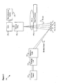
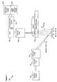
- FIG. 1 illustrates an EBT imaging system 100 formed in accordance with an embodiment of the present invention.
- the system 100 includes an electron source 110, a focusing coil 120, deflection coils 130, target rings 140-143, a data acquisition system (DAS) 150, a reconstruction system 155, a detector array 160, and an object positioner 170.
- the electron source 110 generates an electron beam that travels to the focusing coil 120.
- the electron beam is focused to create a narrow, elliptical beam spot on the target rings 140-143.
- the deflection coils 130 the electron beam is deflected to sweep along one of the target rings 140-143.
- the contacted target rings 140-143 When the focused electron beam hits one of the target rings 140-143, the contacted target rings 140-143 emit a fan beam of x-rays.
- the point at which electrons from the electron beam are deflected onto the target ring 140 is referred to as the "beam spot" and serves as a source of imaging x-rays.
- the target rings 140-143 are made of tungsten.
- the electron beam may be swept along a 210 degree arc to produce, at each spot along the arc, a fan beam of x-rays.
- the x-rays emitted from the target rings 140-143 pass through the object, such as a patient, for example, that is located on the object positioner 170.
- the object positioner 170 may be a table, a support, a wall bucky, or other movable or non-movable positioner, for example.
- the x-rays then impinge upon the detector array 160.
- the detector array 160 includes at least one row of detector elements.
- the detector elements of the detector array 160 generate signals in response to the impinging x-rays.
- the signals are transmitted from the detector array 160 to the DAS 150.
- the DAS 150 collects the data and sends the data to a reconstruction system 155.
- the reconstruction system 155 analyzes the signals and generates a medical diagnostic image from the data obtained from the detector array 160.
- the reconstruction system 155 may also store data or transmit data to an external processor or memory, for example.
- the reconstruction system 155 may be embodied in software and/or in hardware, for example.
- the detector array 160 receives x-rays from several angles, along the arc over which the beam is swept, to produce a set of x-ray projections.
- the projection data is received by the DAS 150, and the total data from one sweep are arranged in a matrix called a sinogram. Within the sinogram, each row contains all projection data for one detector element, and each column contains data at a certain sample number for that detector element.
- the reconstruction system 155 may reconstruct a two-dimensional image, typically characterizing an axial slice of the object imaged. Backprojection or another reconstruction technique may be used to reconstruct the two-dimensional image.
- the resulting image may contain streaks or image artifacts (such as ghost images, for example) due to imperfections or inaccuracies in the system 100 and position of system 100 components. Examples of inaccuracies include errors in detector position or mischaracterization of the motion of the beam spot. Calibration of the system 100 may help to reduce or eliminate streaks or image artifacts to improve image quality. A phantom may be used to calibrate the system 100 to improve image quality and accuracy, for example.
- FIG. 2 illustrates a multipin phantom 200 used for system geometrical calibration in accordance with an embodiment of the present invention.
- the multipin phantom 200 includes a block 210 of foam or other similar material.
- the multipin phantom 200 also includes a plurality of pins placed on or in the block 210. Multiple pins enable the phantom 200 to triangulate on system 100 components, such as the detector array 160 and the individual detectors of the detector array 160 and electron beam, for example, and obtain additional measurements, such as radius, motion, and position, for example.
- the multipin phantom 200 includes pins 220-227.
- the pins may include a metal, such as tungsten, for example.
- the pins 220-227 are placed roughly in a circle and are aligned along an axis of the detector array 160.
- the pins 220-227 may be enclosed in a cylinder of plastic for protection.
- the multipin phantom 200 may be attached to a smaller cylinder that allows the multipin phantom 200 to be mounted on a centermount of the object positioner 170.
- FIG. 3 illustrates a flow diagram 300 for a method for calibrating a medical diagnostic imaging system 100 in accordance with an embodiment of the present invention.
- steps of the method will be described in further detail below.
- positions of the elements of the detector array 160, coefficients of energy beam or source motion, and other manufacturer information are preloaded.
- the multipin phantom 200 is placed on the object positioner 170, and a scan is acquired.
- phantom pin locations are analyzed. Using the theoretical locations of the elements in the detector array 160 and theoretical motion of the beam spot along the target rings 140-143, a rough estimation of the locations of pins 220-227 in the phantom 200 is made.
- the positions of the pins 220-227 and the motion of the beam spot along the target rings 140-143 is refined in a calculation that assumes the detector elements to be in their ideal location.
- the refined pin positions and beam spot motion are used to refine the positions of the detector elements.
- a quality metric called "cluster error" (defined below) is calculated and used to decide if the measurement of the detector element and beam spot positions is sufficient. If measurement is not sufficient, refinement continues in iterations of the above process.
- step 310 theoretical (or ideal or desired) component position data is preloaded.
- the theoretical data may be the expected position of the center of the detector array 160 and of the individual detector elements in the detector array 160, as well as coefficients describing the radial and angular motion of the beam spot produced by the energy source 110.
- the preload of desired data may be preceded by a blank scan to account for background or noise in the EBT imaging system 100.
- step 320 the multipin phantom 200 is scanned.
- the multipin phantom 200 may be placed on the object positioner 170, without concern for the precise location of the multipin phantom 200.
- the positions of the detectors in the detector array 160 and the motion of the electron beam are "frozen" at the assumed or theoretical values.
- a scan with the multipin phantom 200 is performed.
- a sinogram is produced from irradiation of the multipin phantom 200 by radiation, such as x-rays, for example, from the target rings 140-143.
- 864 detector elements with 864 samples each may be included in the detector array 160, and eight pins 220-227 may be included in the multipin phantom 200.
- the sinogram obtained from the detector array 160 is an 864-by-864 sinogram.
- a trace of pins 220-227 through the sinogram is performed to identify the positions of individual pins 220-227 in the sinogram. Areas of high attenuation are assumed to be pin 220-227 shadows and are characterized for their central points and traced through the sinogram. Pin 220-227 position overlaps and other data may also be removed.
- a sample may be obtained every 40 microseconds.
- the time at which the center of a pin 220-227 is detected may be a fractional sample number, such as sample number 1.25.
- the result is an 864-by-8 table of pin 220-227 samples sorted by pin number (hereinafter, pin sample table). Pins 220-227 are identified by a sample number that corresponds to the time at which the sample was obtained (e.g., the time at which the center of the pin 220-227 was observed).
- step 340 the detector array 160 position is "frozen” or held constant at the values calculated in step 330.
- New values for the coefficients describing the motion of the beam spot on the target rings 140-143 and pin 220-227 positions are refined from values obtained in previous steps. The mathematical method of this refinement will be described in detail below.
- step 350 the source 110 and pin 220-227 positions are "frozen” or held constant at the values calculated in step 340, and the detector array 160 positions are refined.
- Detector position refinement proceeds in a manner similar to the pin 220-227 position refinement of step 340.
- pin 220-227 positions and electron beam or source 110 motion may be used to triangulate on each detector position in the detector array 160.
- each entry in the pin sample table can be turned into a hypothetical ray from the detector element to the target ring 140-143.
- One end of the detector-target ray is defined by the position of the detector element, while the other is defined by the location of the beam spot at the time that detector element saw the pin 220-227.
- Figure 4 illustrates a ray tracing 400 used in accordance with an embodiment of the present invention.
- a ray extends from a detector element 465 to the target ring 140.
- the actual position of the pin 220 may be unknown.
- centroid of the rays is computed.
- the centroid is defined as a position in space which minimizes, in a least squares sense, the distance of closest approach of each ray to the centroid.
- the centroid is then assumed to be the position of the pin 220-227 for subsequent calculations.
- the least squares method is used to solve a set of equations with more equations than unknown variables. Accordingly, the answer achieved is not an exact solution but rather a solution that minimizes the sum of the squares of the residual errors.
- Figure 5 illustrates a clustering 500 of rays analyzed with a least-squares method used in accordance with an embodiment of the present invention.
- a plurality of rays from detector elements to the target ring 140-143 overlap to form the centroid in the region of the actual pin.
- the variation among the rays may be used to determine the accuracy of the system of equations describing the pin positions, detector element positions, and beam motion.
- cluster error is defined as the average distance by which each detector-target ray misses its own centroid. In a perfect system, cluster error would be zero. In practice, a cluster error of 5 microns, for example, usually indicates a sufficiently self-consistent solution for streak-free images.
- step 370 if the cluster error is above a certain threshold, refinement continues for the positions of the detector elements and the pins 220-227, along with source 110 motion as a function of time. Refinement continues according to the steps described above, starting at step 340, for example. For example, if the average distance by which rays miss the centroids of the pins 220-227 is more than ten microns, the refinement iterations continue. Each iteration of refinement may more precisely determine positions and characteristics. If the cluster error is below a certain threshold (ten microns, for example), the pin 220-227, detector array 160, and source 110 calculations are sufficient, and system 100 operation (e.g., imaging) may proceed.
- a certain threshold ten microns, for example
- the detector position and source 110 motion may be used in reconstruction of a medical diagnostic image through backprojection or other imaging method, for example.
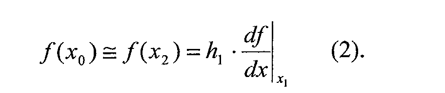
- approximations may be refined to produce x 3 , x 4 , etc., each of which is closer to the desired value x 0 . That is, the input parameter may be refined until the theoretical function acting on the input parameter produces the desired observed value.
- multiple parameters may be simultaneously optimized to produce a close theoretical match to thousands of detector-pin "events" visible in the sinogram of the multipin phantom 200.
- the parameters include positions of each pin 220-227, positions of the detector elements in the detector array 160, and the coefficients of the Fourier series describing the motion of the electron beam source in radius and angle, for example.
- the error (difference between theoretical sample prediction q s and measured sample number q m ) may be written as where R p represents the radius of pin P, ⁇ p represents the angle of pin P, rc j represents the j th radial coefficient of beam motion, and ac j represents the j th angular coefficient of beam motion.
- the measured sample value of pin p in detector element d is roughly equal to the theoretical value plus the derivative of the sample function with respect to pin p 's radius times ⁇ R , plus the derivative with respect to pin p 's angle times ⁇ , plus the derivatives multiplied by the deltas of the source coefficient terms, etc.
- a desired result of the calculation is the values of the deltas ("V") that minimize the difference between measured pin sample values and theoretical values obtained by applying the system model ("f') to the parameter values (i.e., pin position, beam motion coefficients, etc.).
- equation (4) is one equation with multiple unknowns, creating simultaneous equations for all pins 220-227 seen by all detector elements in the detector array 160 results in more equations than unknowns.
- an adjustment to the parameters may be determined using singular value decomposition (SVD). SVD minimizes, in a least-squares sense, the disagreement between theoretical sample values and the empirically measured values.
- the error vector E may be represented as follows:
- the matrix P includes a number of rows equal to the number of detector elements n in the detector array 160 in the system 100 multiplied by the number n of pins 220-227.
- the number of columns in the matrix P is equal to twice the number n of pins 220-227 (one term for each radius, one term for each angle) plus the number of source coefficients.
- the first set of columns represents derivative terms for the pin positions, varying the radius and angle of each pin according to sample number.
- the second set of columns varies the radius coefficients of the source electron beam.
- the third set of columns varies the angle coefficients of the source.
- Rays may be drawn from the target 140-143 through the pins 220-227.
- a point of convergence is calculated.
- the detector element position is updated to the point of convergence, barring errors or unlikely results.
- the process of setting up the system of equations, solving the system, and clustering of detector elements may then be repeated until a sufficient answer is obtained.
- motion and other characteristics of the energy beam may be modified based on the above described calibration method. For example, iterative calibration of the detector array 160 and energy source 110 is performed, as described above in reference to Figures 1, 2 and 3. Then, beam spot motion information is used to adjust currents applied to the deflection coils 130 coils. A complete set of coil currents for a scan is called a "tune".
- Figure 7 illustrates an electron beam tuning system 700 formed in accordance with an embodiment of the present invention.
- the system 700 includes a radial beam correction module 780 and an angular beam adjustment module 790.
- the radial beam correction module 780 and the angular beam adjustment module 790 may be separate units or may be combined in a single unit.
- the radial beam correction module 780 and the angular beam adjustment module 790 may be embodied in hardware and/or in software.
- the system 700 may be used in conjunction with an electron source 710, a focusing coil 720, deflection coils 730, target rings 740-743, a DAS 750, a reconstruction system 755, a detector array 760, an object positioner 770, and a multipin phantom 775.
- the electron source 710, focusing coil 720, deflection coil 730, target rings 740-743, DAS 750, reconstruction system 755, detector array 760, object positioner 770, and multipin phantom 775 are similar to the components described above in relations to Figure 1 and Figure 2.
- tuning is similar to calibration described above.
- the multipin phantom 775 is placed on the object positioner 770 without particular regard to accuracy.
- a scan is acquired.
- the iterative computations previously described are performed to characterize the motion of the beam spot along the target rings 140-143.
- coil currents may be adjusted to optimize beam spot and/or electron beam movement.
- Coil currents for the deflection coil are stored as a series of deflection update blocks (DUBs).
- a DUB represents a single "quantum" of coil currents sent to each deflection coil. In certain embodiments, a DUB is stored for every twenty microseconds. Thus, a single deflection buffer may contain thousands of DUBs.
- the radius of the beam spot is examined at the time of each DUB. If the radius is too large (too much deflection), the dipole currents in the deflection coil are decreased by a scale factor proportional to the size of the deviation from an ideal tune. If the radius is too small (not enough deflection), the dipole currents are increased by a scale factor proportional to the size of the deviation from an ideal tune.
- the above process may be iterated (rescan the multipin phantom 775 with the new tune, redo the multipin phantom 775 calibration, and re-correct the deflection buffers) to produce a set of coil currents with a desired radial flatness.
- the angular motion of the electron beam may also be adjusted using information from the multipin phantom 775.
- An optimal tune produces a beam spot that moves with a constant angular velocity.
- An initial tune may have angular accelerations and decelerations. Deviations from the desired angular velocity may be flattened out on a DUB-by-DUB basis.
- Each DUB corresponds to a specified time; hence the desired angular position of the beam spot for each DUB is known.
- the actual angular position at a given time is contained in a beam spot position file calculated using the multipin phantom 775. Although the beam spot goes through all the correct angles, the beam spot may not be at the correct angle at the correct time.
- Linear combination is performed for every DUB in the deflection buffer. Through linear combination, the angular deviations are "flattened," and a constant angular velocity is approached. In some embodiments, the flattening process is iterated to approach the desired angular velocity. Physical limitations of the deflection coil 730 and focusing coil 720 and effects of the previously described radial modifications being performed along with the angular modifications may result in iteration.
- Figure 8 illustrates a flow diagram 800 for a method for adjusting an electron beam used in accordance with an embodiment of the present invention.
- pin positions, detector element positions, and electron beam motion parameters are determined through estimation and refinement according to steps 310-370 described above.
- the electron beam may be adjusted as described below.
- Electron beam and beam spot motion parameters, as well as other parameters, such as pin positions and detector element positions, may be stored in a file.
- the file such as the beam spot motion file, may be loaded or retrieved in the system 700 for use in adjusting the electron beam.
- step 380 currents for the deflection coils 730 are loaded from a series of deflection update blocks (DUBs). Then, at step 385, the radius of the electron beam spot is examined at the time of each DUB. If the radius is too large (indicating too much deflection, for example), the dipole currents in the deflection coil are decreased by a scale factor proportional to the size of the deviation from an ideal coil current or tune. If the radius is too small (indicating not enough deflection, for example), the dipole currents are increased by a scale factor proportional to the size of the deviation from an ideal tune.
- DUBs deflection update blocks
- DUBS are adjusted to put the beam at a proper angle as a function of time.
- the coil currents are modified to make the beam spot sweep along the targets 140-143 with the correct constant angular velocity.
- the adjusted coil current values are stored.
- the adjusted coil currents aim and focus the electron beam in the electromagnetic focusing coil 20 and deflection coils 730 to strike a desired position on the target rings 740-743 at a desired time.
- the above steps may be repeated as necessary to adjust the electron beam.
Landscapes
- Health & Medical Sciences (AREA)
- Engineering & Computer Science (AREA)
- Life Sciences & Earth Sciences (AREA)
- Medical Informatics (AREA)
- Physics & Mathematics (AREA)
- Radiology & Medical Imaging (AREA)
- Heart & Thoracic Surgery (AREA)
- Veterinary Medicine (AREA)
- Biophysics (AREA)
- High Energy & Nuclear Physics (AREA)
- Public Health (AREA)
- Nuclear Medicine, Radiotherapy & Molecular Imaging (AREA)
- Optics & Photonics (AREA)
- Pathology (AREA)
- General Health & Medical Sciences (AREA)
- Biomedical Technology (AREA)
- Animal Behavior & Ethology (AREA)
- Molecular Biology (AREA)
- Surgery (AREA)
- Remote Sensing (AREA)
- Computer Networks & Wireless Communication (AREA)
- General Physics & Mathematics (AREA)
- Radar, Positioning & Navigation (AREA)
- Pulmonology (AREA)
- Theoretical Computer Science (AREA)
- Apparatus For Radiation Diagnosis (AREA)
- Measurement Of Radiation (AREA)
- Testing Or Measuring Of Semiconductors Or The Like (AREA)
Abstract
Description







Claims (10)
- A multipin phantom (200) for calibrating an imaging system (100), said phantom (200) comprising:a block (210) for housing a plurality of pins (220-227); anda plurality of pins (220-227) placed in said block (210) to enable computation of detector element positions of an imaging system (100).
- The phantom (200) of claim 1, wherein said plurality of pins (220-227) comprise metal pins arranged in a circular configuration.
- The phantom (200) of claim 1, wherein said plurality of pins (220-227) are aligned along an axis oriented to extend parallel to a plane containing detector elements of said imaging system (100).
- A method (300) for calibrating an imaging system (100) having an array (160) of detector elements arranged with respect to a reference position and having an energy source (110) moving in a pattern to irradiate the array (160) of detector elements, the method (300) comprising:initiating estimated detector positions for the array (160) of detector elements and an estimated motion pattern for the energy source (110), said estimated detector positions and motion pattern being defined with respect to a reference position in the imaging system (100) (310);scanning a phantom (200) having pins (220-227) located at positions in the phantom (200) (320);calculating estimated pin (220-227) positions for the pins (220-227) in the phantom (200), with respect to the reference position, based on at least one of said estimated detector positions and motion pattern (330); andmodifying at least one of said estimated detector positions and motion pattern based on at least two of said estimated detector positions, motion pattern and pin (220-227) positions (340, 350).
- The method of claim 4, further comprising determining an amount of error in at least one of said estimated detector positions, motion pattern and pin (220-227) positions; and, when the amount of error exceeds a threshold, repeating said calculating and modifying steps (360, 370).
- The method of claim 4, further comprising:repeating said calculating and modifying steps at least once to obtain first and second estimated detector positions, motion pattern and pin (220-227) positions; andcalculating an amount of error between said first and second estimated detector positions, motion pattern and pin (220-227) positions (360).
- The method of claim 4, further comprising:determining actual pin (220-227) positions from the scan of the phantom (200); andcalculating a difference between said estimated and actual pin (220-227) positions.
- A system for improved calibration of a diagnostic imaging system, said system comprising:an array (160) of detector elements arranged with respect to a reference position;an energy source (110) moving in a pattern to irradiate said array (160) of detector elements;a phantom (200) having pins (220-227) located at positions in said phantom (200); anda reconstruction system (155) calculating estimated pin (220-227) positions for said pins (220-227) in said phantom (200), with respect to said reference position, based on at least one of estimated detector positions and estimated motion pattern of said energy source (110), said reconstruction system (155) modifying at least one of the estimated detector positions and motion pattern based on at least two of the estimated detector positions, motion pattern, and pin (220-227) positions.
- The system of claim 8, wherein said reconstruction system (155) modifies at least one of the estimated detector positions and motion pattern by computing an error vector E = h * P, wherein E represents an error associated with at least one of the estimated detector positions, motion pattern and pin (220-227) positions, h denotes adjustments to produce more accurate estimated detector positions, motion pattern and pin (220-227) positions and P represents a matrix of derivatives for detector-phantom pin (220-227) samples with respect to the detector positions, motion pattern and pin (220-227) positions.
- The system of claim 18, wherein the motion pattern of said energy source (110) is defined in part by an energy beam radius or angle.
Applications Claiming Priority (6)
| Application Number | Priority Date | Filing Date | Title |
|---|---|---|---|
| US35956202P | 2002-02-25 | 2002-02-25 | |
| US359562P | 2002-02-25 | ||
| US65699 | 2002-11-11 | ||
| US10/065,699 US7006594B2 (en) | 2002-02-25 | 2002-11-11 | Method and apparatus for reconstruction calibration of detector position and source motion based on a multi-pin phantom |
| US65700 | 2002-11-11 | ||
| US10/065,700 US7269243B2 (en) | 2002-02-25 | 2002-11-11 | Method and apparatus for controlling electron beam motion based on calibration information |
Publications (2)
| Publication Number | Publication Date |
|---|---|
| EP1346688A2 true EP1346688A2 (en) | 2003-09-24 |
| EP1346688A3 EP1346688A3 (en) | 2003-12-03 |
Family
ID=27792088
Family Applications (2)
| Application Number | Title | Priority Date | Filing Date |
|---|---|---|---|
| EP03251107A Withdrawn EP1346688A3 (en) | 2002-02-25 | 2003-02-25 | Method and apparatus for reconstruction calibration of detector position and source motion based on a multi-pin phantom |
| EP03251120A Withdrawn EP1346689A3 (en) | 2002-02-25 | 2003-02-25 | Method and apparatus for controlling electron beam motion based on calibration information |
Family Applications After (1)
| Application Number | Title | Priority Date | Filing Date |
|---|---|---|---|
| EP03251120A Withdrawn EP1346689A3 (en) | 2002-02-25 | 2003-02-25 | Method and apparatus for controlling electron beam motion based on calibration information |
Country Status (3)
| Country | Link |
|---|---|
| EP (2) | EP1346688A3 (en) |
| JP (2) | JP2003265458A (en) |
| CN (2) | CN1326091C (en) |
Cited By (1)
| Publication number | Priority date | Publication date | Assignee | Title |
|---|---|---|---|---|
| WO2024212134A1 (en) * | 2023-04-12 | 2024-10-17 | Shanghai United Imaging Healthcare Co., Ltd. | Systems and methods for position correction of imaging planes of a multi-energy computed tomograph apparatus |
Families Citing this family (21)
| Publication number | Priority date | Publication date | Assignee | Title |
|---|---|---|---|---|
| CN100403988C (en) * | 2004-04-29 | 2008-07-23 | Ge医疗系统环球技术有限公司 | X-ray geometric structure measurement method and X-ray CT device |
| DE102005007938A1 (en) * | 2005-02-23 | 2006-08-31 | Siemens Ag | X-ray device moving position adjusting device, has sensors to detect actual moving position of holder relative to support in mutual contact-free manner and indicator medium to indicate detected position relative to moving position of holder |
| CN100381103C (en) * | 2005-03-22 | 2008-04-16 | 东软飞利浦医疗设备系统有限责任公司 | A Correction Method of Geometric Parameters of CT Machine |
| DE102006032607B4 (en) | 2006-07-11 | 2011-08-25 | Carl Zeiss Industrielle Messtechnik GmbH, 73447 | Arrangement for generating electromagnetic radiation and method for operating the arrangement |
| EP2536339B1 (en) | 2010-02-18 | 2024-05-15 | Maui Imaging, Inc. | Point source transmission and speed-of-sound correction using multi-aperture ultrasound imaging |
| US9668714B2 (en) | 2010-04-14 | 2017-06-06 | Maui Imaging, Inc. | Systems and methods for improving ultrasound image quality by applying weighting factors |
| US8694074B2 (en) * | 2010-05-11 | 2014-04-08 | Rhythmia Medical, Inc. | Electrode displacement determination |
| JP6092109B2 (en) | 2010-10-13 | 2017-03-08 | マウイ イマギング,インコーポレーテッド | Concave ultrasonic transducer and 3D array |
| WO2013082455A1 (en) | 2011-12-01 | 2013-06-06 | Maui Imaging, Inc. | Motion detection using ping-based and multiple aperture doppler ultrasound |
| JP6438769B2 (en) | 2012-02-21 | 2018-12-19 | マウイ イマギング,インコーポレーテッド | Determination of material hardness using multiple aperture ultrasound. |
| WO2014026185A1 (en) * | 2012-08-10 | 2014-02-13 | Maui Imaging, Inc. | Calibration of multiple aperture ultrasound probes |
| CN103676827A (en) | 2012-09-06 | 2014-03-26 | Ip音乐集团有限公司 | System and method for remotely controlling audio equipment |
| US10512441B2 (en) | 2013-08-29 | 2019-12-24 | Siemens Healthcare Gmbh | Computed tomography having motion compensation |
| US9883848B2 (en) | 2013-09-13 | 2018-02-06 | Maui Imaging, Inc. | Ultrasound imaging using apparent point-source transmit transducer |
| KR102617888B1 (en) | 2014-08-18 | 2023-12-22 | 마우이 이미징, 인코포레이티드 | Network-based ultrasound imaging system |
| KR102681141B1 (en) | 2015-03-30 | 2024-07-02 | 마우이 이미징, 인코포레이티드 | Ultrasonic imaging systems and methods for detecting object motion |
| CN108449977B (en) * | 2015-09-23 | 2021-06-25 | 棱镜传感器公司 | Obtain measurement information from the X-ray detector on the edge and determine the orientation of the X-ray detector on the edge relative to the direction of the incoming X-ray |
| EP4697068A3 (en) | 2016-01-27 | 2026-04-22 | Maui Imaging, Inc. | Ultrasound imaging with sparse array probes |
| CN111261313B (en) * | 2020-01-17 | 2021-01-05 | 桂林狮达技术股份有限公司 | Calibration method for scanning system of charged particle beam processing equipment |
| JP7724853B2 (en) | 2020-10-21 | 2025-08-18 | マウイ イマギング,インコーポレーテッド | Systems and methods for tissue characterization using multiple aperture ultrasound |
| CN116635162A (en) | 2020-11-02 | 2023-08-22 | 毛伊图像公司 | Systems and methods for improving ultrasound image quality |
Family Cites Families (14)
| Publication number | Priority date | Publication date | Assignee | Title |
|---|---|---|---|---|
| US4130759A (en) * | 1977-03-17 | 1978-12-19 | Haimson Research Corporation | Method and apparatus incorporating no moving parts, for producing and selectively directing x-rays to different points on an object |
| US4344183A (en) * | 1980-04-14 | 1982-08-10 | Radiation Measurements, Inc. | Measuring tool for computer assisted tomographic scanner |
| US4631741A (en) * | 1984-04-05 | 1986-12-23 | Imatron, Inc. | Beam spot monitoring arrangement for use in a scanning electron beam computed tomography scanner and method |
| JPH01185246A (en) * | 1988-01-19 | 1989-07-24 | Toshiba Corp | X-ray photographing device |
| DE59009026D1 (en) * | 1990-06-19 | 1995-06-08 | Siemens Ag | Medical device. |
| DE19608497C2 (en) * | 1996-03-05 | 2002-05-02 | Siemens Ag | X-ray diagnostic device |
| US5712895A (en) * | 1997-01-14 | 1998-01-27 | Picker International, Inc. | Rotational digital subtraction angiography phantom |
| DE19703556A1 (en) * | 1997-01-31 | 1998-08-06 | Philips Patentverwaltung | Method and arrangement for determining the position in X-ray imaging |
| US5841835A (en) * | 1997-03-31 | 1998-11-24 | General Electric Company | Apparatus and method for automatic monitoring and assessment of image quality in x-ray systems |
| US5923727A (en) * | 1997-09-30 | 1999-07-13 | Siemens Corporate Research, Inc. | Method and apparatus for calibrating an intra-operative X-ray system |
| US6148057A (en) * | 1998-11-02 | 2000-11-14 | Analogic Corporation | Apparatus and method for calibrating detectors in a computed tomography scanner |
| US6325539B1 (en) * | 1998-12-31 | 2001-12-04 | General Electric Company | Calibration simplification for a computed tomograph system |
| US6292171B1 (en) * | 1999-03-31 | 2001-09-18 | Seiko Epson Corporation | Method and apparatus for calibrating a computer-generated projected image |
| DE19926098C2 (en) * | 1999-06-08 | 2003-05-15 | Siemens Ag | X-ray system |
-
2003
- 2003-02-24 JP JP2003045288A patent/JP2003265458A/en not_active Withdrawn
- 2003-02-24 JP JP2003045287A patent/JP2003305035A/en not_active Withdrawn
- 2003-02-25 CN CNB031070531A patent/CN1326091C/en not_active Expired - Fee Related
- 2003-02-25 EP EP03251107A patent/EP1346688A3/en not_active Withdrawn
- 2003-02-25 CN CNB031070523A patent/CN100337591C/en not_active Expired - Fee Related
- 2003-02-25 EP EP03251120A patent/EP1346689A3/en not_active Withdrawn
Cited By (1)
| Publication number | Priority date | Publication date | Assignee | Title |
|---|---|---|---|---|
| WO2024212134A1 (en) * | 2023-04-12 | 2024-10-17 | Shanghai United Imaging Healthcare Co., Ltd. | Systems and methods for position correction of imaging planes of a multi-energy computed tomograph apparatus |
Also Published As
| Publication number | Publication date |
|---|---|
| CN1443512A (en) | 2003-09-24 |
| JP2003305035A (en) | 2003-10-28 |
| CN100337591C (en) | 2007-09-19 |
| JP2003265458A (en) | 2003-09-24 |
| CN1444182A (en) | 2003-09-24 |
| EP1346689A3 (en) | 2003-12-03 |
| CN1326091C (en) | 2007-07-11 |
| EP1346688A3 (en) | 2003-12-03 |
| EP1346689A2 (en) | 2003-09-24 |
Similar Documents
| Publication | Publication Date | Title |
|---|---|---|
| US7006594B2 (en) | Method and apparatus for reconstruction calibration of detector position and source motion based on a multi-pin phantom | |
| EP1346689A2 (en) | Method and apparatus for controlling electron beam motion based on calibration information | |
| US7269243B2 (en) | Method and apparatus for controlling electron beam motion based on calibration information | |
| Beque et al. | Characterization of pinhole SPECT acquisition geometry | |
| US6960020B2 (en) | Image positioning method and system for tomosynthesis in a digital X-ray radiography system | |
| US6366638B1 (en) | Methods and apparatus for CT scout image processing | |
| US6561695B2 (en) | Calibration table for a cone-beam CT-apparatus | |
| US7929659B2 (en) | System and method for generating computed tomography images | |
| CN111728632A (en) | Ray detection device, ray detection method and CT image reconstruction method | |
| US20050152502A1 (en) | Alignment systems and methods for radiographic imaging systems | |
| US7277522B2 (en) | Method for focus adjustment in a CT apparatus | |
| CN111166364B (en) | Method and system for measuring rotation center of flat panel detector based on optical photography | |
| JP2006006939A (en) | Tomography apparatus and system angle determination method of tomography apparatus imaging system | |
| US7286631B2 (en) | Method and apparatus for tomosynthesis image quality control | |
| CN117631268A (en) | X-ray correction device and correction method based on correlated imaging | |
| JP2019164132A (en) | GEOMETRIC ALIGNMENT, SAMPLE MOTION CORRECTION, AND INTENSITY NORMALIZATION OF COMPUTED TOMOGRAPHY PROJECTIONS USING π-LINE OPTIMIZATION | |
| JP7746450B2 (en) | System and method for CT detector calibration using a wire phantom | |
| JP2011212036A (en) | Radiation imaging system | |
| US7111985B2 (en) | Method and system for measuring table sag | |
| Talebinezhad et al. | A straightforward and analytical method for precise X-ray CT magnification correction | |
| CN110292390A (en) | CT layers of sensitivity curve test body mould Set-up errors bearing calibration | |
| US20260026768A1 (en) | Systems and methods for automated phantom centering | |
| RU2776773C2 (en) | Geometric combination, sample movement adjustment and normalization of intensity of computer tomography projections using pi-lines optimization | |
| CN119882020A (en) | Collimator performance test method, device, equipment and storage medium | |
| CN116531014A (en) | Die body method for high-precision calibration of cone beam CT rotation center and SOD |
Legal Events
| Date | Code | Title | Description |
|---|---|---|---|
| PUAI | Public reference made under article 153(3) epc to a published international application that has entered the european phase |
Free format text: ORIGINAL CODE: 0009012 |
|
| AK | Designated contracting states |
Kind code of ref document: A2 Designated state(s): AT BE BG CH CY CZ DE DK EE ES FI FR GB GR HU IE IT LI LU MC NL PT SE SI SK TR |
|
| AX | Request for extension of the european patent |
Extension state: AL LT LV MK RO |
|
| PUAL | Search report despatched |
Free format text: ORIGINAL CODE: 0009013 |
|
| AK | Designated contracting states |
Kind code of ref document: A3 Designated state(s): AT BE BG CH CY CZ DE DK EE ES FI FR GB GR HU IE IT LI LU MC NL PT SE SI SK TR |
|
| AX | Request for extension of the european patent |
Extension state: AL LT LV MK RO |
|
| 17P | Request for examination filed |
Effective date: 20040603 |
|
| AKX | Designation fees paid |
Designated state(s): DE NL |
|
| STAA | Information on the status of an ep patent application or granted ep patent |
Free format text: STATUS: THE APPLICATION IS DEEMED TO BE WITHDRAWN |
|
| 18D | Application deemed to be withdrawn |
Effective date: 20090901 |