EP1346660A1 - Hair drier having minus ion producer - Google Patents
Hair drier having minus ion producer Download PDFInfo
- Publication number
- EP1346660A1 EP1346660A1 EP01272290A EP01272290A EP1346660A1 EP 1346660 A1 EP1346660 A1 EP 1346660A1 EP 01272290 A EP01272290 A EP 01272290A EP 01272290 A EP01272290 A EP 01272290A EP 1346660 A1 EP1346660 A1 EP 1346660A1
- Authority
- EP
- European Patent Office
- Prior art keywords
- air
- ion
- minus
- flow channel
- housing
- Prior art date
- Legal status (The legal status is an assumption and is not a legal conclusion. Google has not performed a legal analysis and makes no representation as to the accuracy of the status listed.)
- Granted
Links
Images


Classifications
-
- A—HUMAN NECESSITIES
- A45—HAND OR TRAVELLING ARTICLES
- A45D—HAIRDRESSING OR SHAVING EQUIPMENT; EQUIPMENT FOR COSMETICS OR COSMETIC TREATMENTS, e.g. FOR MANICURING OR PEDICURING
- A45D20/00—Hair drying devices; Accessories therefor
- A45D20/04—Hot-air producers
- A45D20/08—Hot-air producers heated electrically
- A45D20/10—Hand-held drying devices, e.g. air douches
- A45D20/12—Details thereof or accessories therefor, e.g. nozzles, stands
-
- A—HUMAN NECESSITIES
- A45—HAND OR TRAVELLING ARTICLES
- A45D—HAIRDRESSING OR SHAVING EQUIPMENT; EQUIPMENT FOR COSMETICS OR COSMETIC TREATMENTS, e.g. FOR MANICURING OR PEDICURING
- A45D2200/00—Details not otherwise provided for in A45D
- A45D2200/20—Additional enhancing means
- A45D2200/202—Ionisation
Definitions
- the present invention relates to a hair drier with a minus ion generator, which has the capability of efficiently supplying minus ions to hair, while drying or setting the hair with hot air.
- minus ions which are minute water in the air coupled with negatively charged oxygen, contact the positively-charged hair, a styling of the hair can be easily performed, while moisture content of the hair being kept. Therefore, it is proposed to place a minus ion generator in a hair drier or a styling brush.
- a conventional hair drier with the minus ion generator is of a structure shown in FIG. 5. That is, an air-flow channel 2 is formed in a tubular housing 1 of this hair drier, so that air sucked from an air-suction inlet 22 provided at one end of the housing 1 is ejected from an air outlet 21 provided at the other end thereof.
- a fan 31 , motor 32 for driving the fan, heater 33 , and the minus ion generator 7 are disposed in the air-flow channel 2 of the housing 1 .
- the numeral 34 designates a grid member 34 attached to the air outlet 21 to prevent foreign matter from getting into the housing 1 .
- the numeral 4 designates a nozzle attached to the air outlet, which has a tapered shape to eject the air flow from its top end opening 41 .
- a grip 35 projects downwardly from the housing 1 , in which electric cords A for supplying electricity to the motor 32 and a power switch 36 are incorporated.
- the power switch 36 when the power switch 36 is turned on, electric power is supplied to the motor 32 , heater 33 , and the minus ion generator 7 .
- the air is sucked into the housing 1 from the air-suction inlet 22 by the fan 31 , and then sent to the downstream side of the air-flow channel.
- the air in the air-flow channel 2 is heated by the heater 33 .
- the heated air is mixed with the minus ions generated by the minus ion generator 7 .
- the air flow including the minus ions is ejected outside from the opening 41 of the nozzle 4 through the air outlet 21 with the grid member 34 .
- the hair drier described above has a problem that the ion generator 7 disposed-in-the-air-flow channel 2 hampers a flow-of air in-the-air-flow channel 2 .
- the ion generator 7 disposed-in-the-air-flow channel 2 hampers a flow-of air in-the-air-flow channel 2 .
- electrical repulsion occurs between the minus ions caught by the grid member 34 and minus ions in the air flow successively supplied, so that it becomes difficult for the minus ions to pass the grid member 34 . Consequently, there is another problem that the supply amount of the minus ions gradually decreases.
- a concern of the present invention is to provide a hair drier with a minus ion generator, which has the capability of efficiently supplying minus ions generated by the minus ion generator to hair, without hampering a flow of air in an air-flow channel.
- the hair drier of the present invention is characterized by comprising an air-flow channel formed in the interior of a housing; a fan and a heater disposed in the air-flow channel; an air outlet for ejecting an air, which is provided at a downstream end of the air-flow channel; an ion-flow channel formed in the housing so as to be separated from the air-flow channel; the minus-ion generator for generating minus ions, which is disposed in the ion-flow channel; and an ion outlet for the minus ions, which is provided at a downstream end of the ion-flow channel.
- the hair drier of the present invention is characterized by comprising a housing having a substantially hollow structure, which has an air suction inlet, air outlet, and an air-flow channel extending therebetween; a fan for sucking an outside air into the housing through the air suction inlet; a heater for heating the air in the air-flow channel; and the minus ion generator; wherein the housing has an ion-flow channel formed as an independent flow channel from the air flow channel, and an ion outlet provided at a different position from the air outlet to eject minus ions generated by the minus ion generator, and wherein the minus ion generator is disposed in the ion-flow channel.
- the minus ions generated by the ion generator are stably supplied from the ion outlet, without being caught by an obstacle such as a grid member, a user can efficiently carry out hair styling by spraying the minus ions to the hair.
- the minus ion generator includes a needle electrode and a ground . electrode spaced away from the needle electrode by a small distance, and a discharge for generating the minus ions is developed between the needle electrode and the ground electrode by applying a negative high voltage to the needle electrode.
- the housing has an air induction path for allowing part of the air running in the air-flow channel to flow in the ion-flow channel.
- the housing has an air induction path for allowing part of the air running in the air-flow channel to flow in the ion-flow channel.
- it is not needed to dispose an additional fan in the housing in order to eject the minus ions generated by the minus ion generator from the ion outlet there are advantages that the hair drier becomes a simple structure as whole, and can be easily downsized. Additionally, as compared with a hair drier with a dedicated fan, power consumption can be reduced.
- the ion outlet is provided in the vicinity of the air outlet.
- the minus ions ejected from the ion outlet are easily mixed with the hot air ejected from the air outlet, it is effective to increase amounts of the minus ions that reach the user's hair.
- the above-described hair drier has an ion switch for switching the minus ion generator to start or stop generating the minus ions.
- the ion switch since the user can control the presence or absence of the minus ions, it is possible to supply the hot air with the minus ions to the hair as need arises. For example, when moist hair is desired, the ion switch is turned on, and when a hairstyle with volume is desired, the ion switch is turned off.
- the ion switch when the ion switch is provided on a surface of the housing and in the vicinity of the minus ion generator, it is possible to easily select the presence or absence of the minus ions by operating the ion switch by one hand, while holding the grip of the hair drier by the other hand.
- the hair drier described above has an ion generation indicator for indicating the start or stop of generating the minus ions by the minus ion generator in conjunction with the ion switch.
- the ion-generation indicator is provided on a surface of the housing and in the vicinity of the minus ion generator. In this case, it is possible to easily check the presence or absence of generating the minus ions.
- this hair drier is mainly composed of a hollow housing 1 having an air suction inlet 22 , air outlet 21 , and an air-flow channel 2 formed therebetween, and a grip 35 , in which a power switch 36 of the drier is disposed.
- the air suction inlet 22 is provided with a main suction inlet 25 formed in an upper surface of the housing and an auxiliary suction inlet 26 formed in a lower surface thereof.
- the air-flow channel 2 is defined between the air suction inlet 22 and the air outlet 21 .
- a fan 31 for sucking an outside air from the air suction inlet 22 into the housing and a heater 33 for heating the air in the air-flow channel are disposed in the air-flow channel 2 .
- the numeral 32 designates a motor for driving the fan 31 . By driving the fan 31 , the air sucked in the housing 1 is heated by the heater 33 , so that the obtained hot air is ejected from the air outlet 21 .
- the fan 31 is of a centrifugal type of taking the air from the main and auxiliary suction inlets 25, 26 into the housing 1 , and ejecting the air from the air outlet 21 provided at the opposite side of the air-flow channel 2 . Since the air flows in the housing from the top and bottom thereof, a smooth air flow can be achieved.
- the air suction inlet 22 may be provided with only the main suction inlet 25 .
- a net-like grid member 34 for preventing inhalation of foreign substance into the housing 1 is attached to theair outlet 21 .
- a nozzle 4 for collecting the air flow in the housing 1 and ejecting it to the outside is also attached to the air outlet 21 .
- the nozzle 4 is formed in such a tapered shape that its aperture diameter decreases toward an end aperture 41 of the nozzle 4 .
- a pair of wings 42 are formed in the nozzle to collect the flow of air in a direction of a substantially center axis of the housing. This pair of the wings 42 are formed such that air flows ejected from clearances between the respective wings and an interior surface of the nozzle are joined to the air flow ejected from a space between the wings.
- a path extending from the air suction inlet 22 of the housing 1 to the end aperture 41 of the nozzle 4 through the air outlet 21 corresponds to the air-flow channel 2 of the hair drier.
- the grip 35 is integrally formed with the housing 1 so as to extend downwardly from the housing surface at a side of the auxiliary suction inlet 26 .
- the grip 35 is of a substantially tubular shape, in which a motor 32 and a power switch 36 for the heater 33 are disposed.
- the minus ion generator 7 is disposed at an upper side in the housing 1 . As explained in detail below, minus ions generated by the minus ion generator 7 are ejected to the outside through an ion-flow channel 5 independently formed from the air-flow channel 2 , and an ion outlet 61 provided at a different position from the air outlet 21 .
- the minus ion generator 7 generates the minus ions that are minute moisture in the air coupled with negatively-charged oxygen.
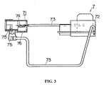
- the minus ion generator 7 is composed of a discharge unit 71 , a high voltage generator 72 , and lead wires 73 electrically connecting therebetween.
- the discharge unit 71 comprises a needle-like electrode 74 , ground electrode 75 spaced away from the needle-like electrode by a required distance, and a casing 76 made of an insulating material to hold these electrodes.
- the needle-like electrode 74 and the ground electrode 75 are respectively connected to the high voltage generator 72 by the lead wires 73 .
- the high voltage generator 72 develops a voltage such that a negative high voltage is applied to the needle-like electrode 74 with reference to the ground electrode 75 .
- a corona discharge (approximately 5 KW) happens between the needle-like electrode 74 and the ground electrode 75 to generate the minus ions.
- the minus ion generator 7 is not limited to the above-described one. Another minus ion generator may be used.
- an outer wall 6 for the ion-flow channel is integrally formed with the housing 1 such that the outer wall is smoothly elevated forwardly from a substantially center portion of the upper surface of the housing 1 , and an ion outlet 61 is opened in the same direction as the air outlet 21 .
- the ion-flow channel 5 is completely separated from the air-flow channel 2 .
- the ion-flow channel 5 is connected to the air-flow channel 2 though an air induction path 9 formed to allow part of the air running in the air-flow channel 2 to flow in the ion-flow channel 5 .
- the part of the air in the air-flow channel 2 passes the minus ion generator 7 though the air induction path 9 , so that the minus ions generated by the ion generator 7 flows in the ion-flow channel 5 together with the part of the air flowed therein, and then supplied from the ion outlet 61 .
- the ion outlet 61 is provided in the vicinity of the air outlet 21 , the minus ions ejected from the ion outlet 61 is mixed with the air ejected from the nozzle 4 attached to the air outlet 21 , and then sprayed on the hair. As a result, it is possible to efficiently spray the minus ions on the hair by help of the flow of the heated air.
- an important feature of the present invention is to independently provide the ion-flow channel 5 connecting to the ion outlet 61 from the air-flow channel 2 for sending the hot air to the air outlet 21 . Therefore, the minus ions generated by the minus ion generator 7 can not come into the air-flow channel 2 .
- an ion switch 81 for switching the minus ion generator 7 to start or stop generating the minus ions is provided at an upper surface of the outer wall 6 for the ion-flow channel.
- an ion generation indicator 82 is provided in proximity to the ion switch 81 to indicate the start or stop of the generation of minus ions by the minus ion generator 7 in conjunction with the ion switch 81 . Therefore, when the ion switch 81 is operated, the presence or absence of the generation of minus ions can be checked by the ion generation indicator 82 . This provides a further improvement in operationality of the hair drier of the present invention.
- an LED 82a is used as the ion generation indicator 82 .
- the function of controlling the air flow of the hair drier is located on the grip 35 , and the function of operating the generation of the minus ions is located on the upper surface of the housing 1 , it is possible to provide the hair drier having an improved operationality and a refined appearance.
- the following is an example of how to use the hair drier described above.
- a user washes hair, and wipes the wet hair with a towel lightly, it is preferred to dry the hair with a hot air, while spraying minus ions from the hair dryer of the present invention. That is, the grip 35 is grasped, and the power switch 36 is turned on to activate the motor 32 and rotate the fan 31 . Thereby, outside air is sucked into the housing 1 through the air suction inlet 22 , and the sucked air is heated by the heater 33 to provide the hot air. .
- the hot air is sent to the nozzle 4 through the grid member 34 disposed in the vicinity of the air outlet 21 of the housing 1 , and then ejected from the end aperture 41 of the nozzle 4 .
- the ion switch 81 is turned on to generate the minus ions by the minus ion generator 7 , so that the minus ions are ejected from the ion outlet 61 .
- minus ions generated by the minus ion generator can be efficiently ejected from the ion outlet, without being caught by an obstacle such as a grid member in the housing.
- the ion generator since the ion generator is disposed in the ion-flow channel other than the air-flow channel the housing, it does not hamper a flow of the hot air running the air-flow channel.
- a user of the hair drier can perform hairstyling with freedom, while spraying larger amounts of the minus ions to the hair.
- by an increase in the amounts of minus ions that reach the hair it is possible to obtain the hair having high moisture content in less time. This achieves moist hair that is easy to perform hairstyling.
- the minus ions ejected from the ion outlet are mixed with the hot air ejected from the air outlet, and then supplied to the user's hair. Therefore, the amounts of minus ions spayed on the hair can be further increased.
Abstract
Description
- The present invention relates to a hair drier with a minus ion generator, which has the capability of efficiently supplying minus ions to hair, while drying or setting the hair with hot air.
- In general, it is said that hair is easy to be positively charged. When minus ions, which are minute water in the air coupled with negatively charged oxygen, contact the positively-charged hair, a styling of the hair can be easily performed, while moisture content of the hair being kept. Therefore, it is proposed to place a minus ion generator in a hair drier or a styling brush.
- For example, a conventional hair drier with the minus ion generator is of a structure shown in FIG. 5. That is, an air-flow channel 2 is formed in a tubular housing 1 of this hair drier, so that air sucked from an air-
suction inlet 22 provided at one end of the housing 1 is ejected from anair outlet 21 provided at the other end thereof. In the air-flow channel 2 of the housing 1, afan 31,motor 32 for driving the fan,heater 33, and theminus ion generator 7 are disposed. In FIG. 5, thenumeral 34 designates agrid member 34 attached to theair outlet 21 to prevent foreign matter from getting into the housing 1. The numeral 4 designates a nozzle attached to the air outlet, which has a tapered shape to eject the air flow from its top end opening 41. In addition, agrip 35 projects downwardly from the housing 1, in which electric cords A for supplying electricity to themotor 32 and apower switch 36 are incorporated. - To use the above-described hair drier, when the
power switch 36 is turned on, electric power is supplied to themotor 32,heater 33, and theminus ion generator 7. The air is sucked into the housing 1 from the air-suction inlet 22 by thefan 31, and then sent to the downstream side of the air-flow channel. Subsequently, the air in the air-flow channel 2 is heated by theheater 33. The heated air is mixed with the minus ions generated by theminus ion generator 7. Thus, the air flow including the minus ions is ejected outside from theopening 41 of the nozzle 4 through theair outlet 21 with thegrid member 34. - However, the hair drier described above has a problem that the
ion generator 7 disposed-in-the-air-flow channel 2 hampers a flow-of air in-the-air-flow channel 2. In addition, since some of the minus ions generated by theion generator 7 are caught by thegrid member 34, electrical repulsion occurs between the minus ions caught by thegrid member 34 and minus ions in the air flow successively supplied, so that it becomes difficult for the minus ions to pass thegrid member 34. Consequently, there is another problem that the supply amount of the minus ions gradually decreases. - In consideration of the above problems, a concern of the present invention is to provide a hair drier with a minus ion generator, which has the capability of efficiently supplying minus ions generated by the minus ion generator to hair, without hampering a flow of air in an air-flow channel.
- That is, the hair drier of the present invention is characterized by comprising an air-flow channel formed in the interior of a housing; a fan and a heater disposed in the air-flow channel; an air outlet for ejecting an air, which is provided at a downstream end of the air-flow channel; an ion-flow channel formed in the housing so as to be separated from the air-flow channel; the minus-ion generator for generating minus ions, which is disposed in the ion-flow channel; and an ion outlet for the minus ions, which is provided at a downstream end of the ion-flow channel.
- More specifically, the hair drier of the present invention is characterized by comprising a housing having a substantially hollow structure, which has an air suction inlet, air outlet, and an air-flow channel extending therebetween; a fan for sucking an outside air into the housing through the air suction inlet; a heater for heating the air in the air-flow channel; and the minus ion generator; wherein the housing has an ion-flow channel formed as an independent flow channel from the air flow channel, and an ion outlet provided at a different position from the air outlet to eject minus ions generated by the minus ion generator, and wherein the minus ion generator is disposed in the ion-flow channel.
- According to the hair drier described above, since the minus ions generated by the ion generator are stably supplied from the ion outlet, without being caught by an obstacle such as a grid member, a user can efficiently carry out hair styling by spraying the minus ions to the hair.
- To achieve the concern described above of the present invention, it is preferred that the minus ion generator includes a needle electrode and a ground . electrode spaced away from the needle electrode by a small distance, and a discharge for generating the minus ions is developed between the needle electrode and the ground electrode by applying a negative high voltage to the needle electrode.
- In addition, it is preferred that the housing has an air induction path for allowing part of the air running in the air-flow channel to flow in the ion-flow channel. In this case, it is possible to more stably supply the minus ions together with the air that comes into the air induction path. Moreover, since it is not needed to dispose an additional fan in the housing in order to eject the minus ions generated by the minus ion generator from the ion outlet, there are advantages that the hair drier becomes a simple structure as whole, and can be easily downsized. Additionally, as compared with a hair drier with a dedicated fan, power consumption can be reduced.
- In addition, it is preferred that the ion outlet is provided in the vicinity of the air outlet. In this case, since the minus ions ejected from the ion outlet are easily mixed with the hot air ejected from the air outlet, it is effective to increase amounts of the minus ions that reach the user's hair. Moreover, there are advantages of preventing a hair damage caused by over-drying and decreasing the occurrence of static electricity.
- In addition, it is preferred that the above-described hair drier has an ion switch for switching the minus ion generator to start or stop generating the minus ions. In this case, since the user can control the presence or absence of the minus ions, it is possible to supply the hot air with the minus ions to the hair as need arises. For example, when moist hair is desired, the ion switch is turned on, and when a hairstyle with volume is desired, the ion switch is turned off. In particular, when the ion switch is provided on a surface of the housing and in the vicinity of the minus ion generator, it is possible to easily select the presence or absence of the minus ions by operating the ion switch by one hand, while holding the grip of the hair drier by the other hand.
- In addition, it is preferred that the hair drier described above has an ion generation indicator for indicating the start or stop of generating the minus ions by the minus ion generator in conjunction with the ion switch. In particular, it is preferred that the ion-generation indicator is provided on a surface of the housing and in the vicinity of the minus ion generator. In this case, it is possible to easily check the presence or absence of generating the minus ions.
- These and still other objects and advantages of the present invention will become more apparent from the best mode for carrying out the present invention explained below, referring to the attached drawings.
-
- FIG. 1 is a longitudinal cross-sectional view of a hair drier with a minus ion generator according to a preferred embodiment of the present invention;
- FIG. 2 is an enlarged cross-sectional view illustrating an ion flow channel of the hair drier of FIG. 1;
- FIG. 3 is a schematic diagram of a structure of the minus ion generator;
- FIG. 4 is a partially cross-sectional top view of the hair drier of FIG. 1; and
- FIG. 5 is a schematic cross-sectional view of a conventional hair drier with a minus ion generator.
-
- Referring to the attached drawings, a hair drier with a minus ion generator according to a preferred embodiment of the present invention is explained below in detail.
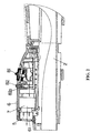
- As shown in FIG. 1, this hair drier is mainly composed of a hollow housing 1 having an
air suction inlet 22,air outlet 21, and an air-flow channel 2 formed therebetween, and agrip 35, in which apower switch 36 of the drier is disposed. - In this embodiment, the
air suction inlet 22 is provided with a main suction inlet 25 formed in an upper surface of the housing and an auxiliary suction inlet 26 formed in a lower surface thereof. In the housing 1, the air-flow channel 2 is defined between theair suction inlet 22 and theair outlet 21. Afan 31 for sucking an outside air from theair suction inlet 22 into the housing and aheater 33 for heating the air in the air-flow channel are disposed in the air-flow channel 2. In the drawings, thenumeral 32 designates a motor for driving thefan 31. By driving thefan 31, the air sucked in the housing 1 is heated by theheater 33, so that the obtained hot air is ejected from theair outlet 21. - The
fan 31 is of a centrifugal type of taking the air from the main and auxiliary suction inlets 25, 26 into the housing 1, and ejecting the air from theair outlet 21 provided at the opposite side of the air-flow channel 2. Since the air flows in the housing from the top and bottom thereof, a smooth air flow can be achieved. Theair suction inlet 22 may be provided with only the main suction inlet 25. - A net-
like grid member 34 for preventing inhalation of foreign substance into the housing 1 is attached totheair outlet 21. A nozzle 4 for collecting the air flow in the housing 1 and ejecting it to the outside is also attached to theair outlet 21. The nozzle 4 is formed in such a tapered shape that its aperture diameter decreases toward anend aperture 41 of the nozzle 4. In addition, a pair of wings 42 are formed in the nozzle to collect the flow of air in a direction of a substantially center axis of the housing. This pair of the wings 42 are formed such that air flows ejected from clearances between the respective wings and an interior surface of the nozzle are joined to the air flow ejected from a space between the wings. Thereby, as compared with the case of using a nozzle having a simple tapered shape, the hot air can be efficiently collected in the direction of the substantially center axis of the housing to further increase a velocity of the air flow. In the hair drier of the present embodiment, a path extending from theair suction inlet 22 of the housing 1 to theend aperture 41 of the nozzle 4 through theair outlet 21 corresponds to the air-flow channel 2 of the hair drier. - The
grip 35 is integrally formed with the housing 1 so as to extend downwardly from the housing surface at a side of the auxiliary suction inlet 26. Thegrip 35 is of a substantially tubular shape, in which amotor 32 and apower switch 36 for theheater 33 are disposed. - In the present invention, as shown in FIG. 2, the
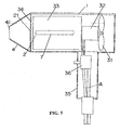
minus ion generator 7 is disposed at an upper side in the housing 1. As explained in detail below, minus ions generated by theminus ion generator 7 are ejected to the outside through an ion-flow channel 5 independently formed from the air-flow channel 2, and anion outlet 61 provided at a different position from theair outlet 21. - The
minus ion generator 7 generates the minus ions that are minute moisture in the air coupled with negatively-charged oxygen. As shown in FIG. 3, theminus ion generator 7 is composed of adischarge unit 71, ahigh voltage generator 72, and leadwires 73 electrically connecting therebetween. Thedischarge unit 71 comprises a needle-like electrode 74,ground electrode 75 spaced away from the needle-like electrode by a required distance, and acasing 76 made of an insulating material to hold these electrodes. The needle-like electrode 74 and theground electrode 75 are respectively connected to thehigh voltage generator 72 by thelead wires 73. - To generate the minus ions by the
minus ion generator 7, thehigh voltage generator 72 develops a voltage such that a negative high voltage is applied to the needle-like electrode 74 with reference to theground electrode 75. Thereby, a corona discharge (approximately 5 KW) happens between the needle-like electrode 74 and theground electrode 75 to generate the minus ions. Theminus ion generator 7 is not limited to the above-described one. Another minus ion generator may be used. - To place the
ion generator 7 in the ion-flow channel 5, as shown in FIGS. 2 and 4, anouter wall 6 for the ion-flow channel is integrally formed with the housing 1 such that the outer wall is smoothly elevated forwardly from a substantially center portion of the upper surface of the housing 1, and anion outlet 61 is opened in the same direction as theair outlet 21. - In this embodiment, at the downstream side of the
ion generator 7, the ion-flow channel 5 is completely separated from the air-flow channel 2. However, at the upstream side of theion generator 7, the ion-flow channel 5 is connected to the air-flow channel 2 though an air induction path 9 formed to allow part of the air running in the air-flow channel 2 to flow in the ion-flow channel 5. Thereby, as shown by the arrow in FIG. 2, the part of the air in the air-flow channel 2 passes theminus ion generator 7 though the air induction path 9, so that the minus ions generated by theion generator 7 flows in the ion-flow channel 5 together with the part of the air flowed therein, and then supplied from theion outlet 61. - When the minus ions are caught by the
grid member 34 or the nozzle 4 placed in the air-flow channel 2 before the minus ions generated by theion generator 7 are ejected from theion outlet 61, a flow of the minus ions to the downstream side is hampered by electrical repulsion caused between the minus ions caught by the above-described member and minus ions in the air flow successively supplied. In the present invention, by forming the ion-flow channel 5 as an independent flow channel from the air-flow channel 2 in the housing 1, it is possible to avoid such an inconvenience that it becomes difficult to supply the minus ions from theion outlet 61. - In addition, since the
ion outlet 61 is provided in the vicinity of theair outlet 21, the minus ions ejected from theion outlet 61 is mixed with the air ejected from the nozzle 4 attached to theair outlet 21, and then sprayed on the hair. As a result, it is possible to efficiently spray the minus ions on the hair by help of the flow of the heated air. - As described above, an important feature of the present invention is to independently provide the ion-flow channel 5 connecting to the
ion outlet 61 from the air-flow channel 2 for sending the hot air to theair outlet 21. Therefore, the minus ions generated by theminus ion generator 7 can not come into the air-flow channel 2. - As shown in FIG. 2, an
ion switch 81 for switching theminus ion generator 7 to start or stop generating the minus ions is provided at an upper surface of theouter wall 6 for the ion-flow channel. Thereby, it is possible to easily select the presence or absence of the generation of minus ions by operating theion switch 81 by one hand, while holding thegrip 35 of the hair drier by the other hand. - In addition, an
ion generation indicator 82 is provided in proximity to theion switch 81 to indicate the start or stop of the generation of minus ions by theminus ion generator 7 in conjunction with theion switch 81. Therefore, when theion switch 81 is operated, the presence or absence of the generation of minus ions can be checked by theion generation indicator 82. This provides a further improvement in operationality of the hair drier of the present invention. In the present embodiment, anLED 82a is used as theion generation indicator 82. Thus, since the function of controlling the air flow of the hair drier is located on thegrip 35, and the function of operating the generation of the minus ions is located on the upper surface of the housing 1, it is possible to provide the hair drier having an improved operationality and a refined appearance. - The following is an example of how to use the hair drier described above. After a user washes hair, and wipes the wet hair with a towel lightly, it is preferred to dry the hair with a hot air, while spraying minus ions from the hair dryer of the present invention. That is, the
grip 35 is grasped, and thepower switch 36 is turned on to activate themotor 32 and rotate thefan 31. Thereby, outside air is sucked into the housing 1 through theair suction inlet 22, and the sucked air is heated by theheater 33 to provide the hot air. . - The hot air is sent to the nozzle 4 through the
grid member 34 disposed in the vicinity of theair outlet 21 of the housing 1, and then ejected from theend aperture 41 of the nozzle 4. To spray the minus ions together with the hot air on the hair, theion switch 81 is turned on to generate the minus ions by theminus ion generator 7, so that the minus ions are ejected from theion outlet 61. Thus, by drying the hair with the hot air containing the minus ions, it is possible to achieve moist hair that is easy to perform hairstyling. - According to the present invention, minus ions generated by the minus ion generator can be efficiently ejected from the ion outlet, without being caught by an obstacle such as a grid member in the housing. In addition, since the ion generator is disposed in the ion-flow channel other than the air-flow channel the housing, it does not hamper a flow of the hot air running the air-flow channel. As a result, a user of the hair drier can perform hairstyling with freedom, while spraying larger amounts of the minus ions to the hair. Moreover, by an increase in the amounts of minus ions that reach the hair, it is possible to obtain the hair having high moisture content in less time. This achieves moist hair that is easy to perform hairstyling.
- In particular, when the ion outlet is provided in the vicinity of the air outlet, the minus ions ejected from the ion outlet are mixed with the hot air ejected from the air outlet, and then supplied to the user's hair. Therefore, the amounts of minus ions spayed on the hair can be further increased.
Claims (9)
- A hair drier with a minus ion generator comprising:an air-flow channel formed in the interior of a housing;a fan and a heater disposed in said air-flow channel;an air outlet for ejecting an air, which is provided at a downstream end of said air-flow channel;an ion-flow channel formed in said housing so as to be separated from said air-flow channel;said minus-ion generator for generating minus ions, which is disposed in said ion-flow channel; andan ion outlet for said minus ions, which is provided at a downstream end of said ion-flow channel.
- The hair drier as set forth in claim 1, wherein said minus ion generator includes a needle electrode and a ground electrode spaced away from said needle electrode by a small distance, and wherein a discharge for generating said minus ions is developed between said needle electrode and said ground electrode by applying a negative high voltage to said needle electrode.
- The hair drier as set forth in claim 1, wherein said housing has an air induction path for allowing part of the air running in said air-flow channel to flow in said ion-flow channel.
- The hair drier as set forth in claim 1, wherein said ion outlet is provided in the vicinity of said air outlet.
- The hair drier as set forth in claim 1 comprising an ion switch for switching said minus ion generator to start or stop generating said minus ions.
- The hair drier as set forth in claim 5, wherein said ion switch is provided on a surface of said housing and in the vicinity of said minus ion generator. .
- The hair drier as set forth in claim 5 comprising an ion generation indicator for indicating the start or stop of generating said minus ions by said minus ion generator in conjunction with said ion switch.
- The hair drier as set forth in claim 7, wherein said ion-generation indicator is provided on a surface of said housing and in the vicinity of said minus ion generator.
- A hair drier with a minus ion generator comprising:wherein said housing has an ion-flow channel formed as an independent flow channel from said air-flow channel, and an ion outlet provided at a different position from said air outlet to eject minus ions generated by said minus ion generator, and wherein said minus ion generator is disposed in said ion-flow channel.a housing having a substantially hollow structure, which has an air suction inlet, air outlet, and an air-flow channel extending therebetween;a fan for sucking an outside air into said housing through said air suction inlet;a heater for heating the air in said air-flow channel; andsaid minus ion generator;
Applications Claiming Priority (3)
| Application Number | Priority Date | Filing Date | Title |
|---|---|---|---|
| JP2000393893A JP3402323B2 (en) | 2000-12-25 | 2000-12-25 | Hair dryer |
| JP2000393893 | 2000-12-25 | ||
| PCT/JP2001/011284 WO2002051282A1 (en) | 2000-12-25 | 2001-12-21 | Hair drier having minus ion producer |
Publications (3)
| Publication Number | Publication Date |
|---|---|
| EP1346660A1 true EP1346660A1 (en) | 2003-09-24 |
| EP1346660A4 EP1346660A4 (en) | 2004-06-02 |
| EP1346660B1 EP1346660B1 (en) | 2005-08-10 |
Family
ID=18859611
Family Applications (1)
| Application Number | Title | Priority Date | Filing Date |
|---|---|---|---|
| EP01272290A Expired - Lifetime EP1346660B1 (en) | 2000-12-25 | 2001-12-21 | Hair drier having minus ion producer |
Country Status (9)
| Country | Link |
|---|---|
| US (1) | US6910281B2 (en) |
| EP (1) | EP1346660B1 (en) |
| JP (1) | JP3402323B2 (en) |
| KR (2) | KR100558788B1 (en) |
| CN (2) | CN1197501C (en) |
| DE (1) | DE60112613T2 (en) |
| HK (2) | HK1056670A1 (en) |
| TW (1) | TWM253255U (en) |
| WO (1) | WO2002051282A1 (en) |
Cited By (5)
| Publication number | Priority date | Publication date | Assignee | Title |
|---|---|---|---|---|
| EP1433401A3 (en) * | 2002-12-27 | 2004-08-25 | Matsushita Electric Works, Ltd. | Hair dryer with minus ion generator |
| WO2006013283A1 (en) * | 2004-07-07 | 2006-02-09 | Seb S.A. | Hair treatment apparatus |
| EP1902643A1 (en) * | 2006-09-22 | 2008-03-26 | Matsushita Electric Works, Ltd. | Ion hair dryer |
| WO2009015802A1 (en) * | 2007-07-27 | 2009-02-05 | Braun Gmbh | Hair care device |
| US20150343166A1 (en) * | 2012-07-31 | 2015-12-03 | Jason Ryu | Apparatus to dry, weigh and sanitize body |
Families Citing this family (35)
| Publication number | Priority date | Publication date | Assignee | Title |
|---|---|---|---|---|
| JP3402327B1 (en) * | 2002-01-18 | 2003-05-06 | 松下電工株式会社 | Hair iron |
| JP2004081693A (en) | 2002-08-28 | 2004-03-18 | Re-Tec:Kk | Gas combustion-type portable dryer and minus ion generating method in the portable dryer |
| KR20020093665A (en) * | 2002-10-02 | 2002-12-16 | 신길승 | Hair dryer for having a negative ion producer |
| JP2004156402A (en) * | 2002-11-08 | 2004-06-03 | Inax Corp | Toilet heating apparatus |
| JP4144788B2 (en) * | 2002-11-19 | 2008-09-03 | 九州日立マクセル株式会社 | Hairdressing tools |
| JP4131169B2 (en) * | 2002-12-27 | 2008-08-13 | 松下電工株式会社 | Hair dryer |
| JP2005198984A (en) * | 2004-01-19 | 2005-07-28 | Matsushita Electric Works Ltd | Hair iron |
| KR100809568B1 (en) | 2004-04-23 | 2008-03-04 | 마츠시다 덴코 가부시키가이샤 | Heating blower with electrostatic atomizing device |
| JP4232695B2 (en) * | 2004-06-14 | 2009-03-04 | パナソニック電工株式会社 | Brushed hair dryer |
| KR100707845B1 (en) | 2004-09-27 | 2007-04-13 | 마츠시다 덴코 가부시키가이샤 | Electrostatic atomizing hairdryer |
| ES2335426T3 (en) | 2005-01-28 | 2010-03-26 | Panasonic Electric Works Co., Ltd. | HAIR DRYER WITH ELECTROSTATIC ATOMIZING DEVICE. |
| US20060227491A1 (en) * | 2005-04-07 | 2006-10-12 | Rovcal, Inc. | Hair blower with positive and negative ion emitters |
| JP4655945B2 (en) * | 2006-01-19 | 2011-03-23 | パナソニック電工株式会社 | Heating blower |
| JP4857851B2 (en) * | 2006-03-28 | 2012-01-18 | パナソニック電工株式会社 | Hair iron |
| JP4665934B2 (en) * | 2006-06-30 | 2011-04-06 | パナソニック電工株式会社 | Heating blower |
| EP1872680B1 (en) * | 2006-06-30 | 2013-08-14 | Panasonic Corporation | Heating and blowing apparatus |
| US20080256825A1 (en) * | 2007-04-17 | 2008-10-23 | Hokwang Industries Co., Ltd. | Hand dryer with visible light indicated sensing area |
| DE102007035247A1 (en) * | 2007-07-27 | 2009-02-19 | Braun Gmbh | Hair care device |
| US20090044420A1 (en) * | 2007-08-16 | 2009-02-19 | Hokwang Industries Co., Ltd. | Light directing hand dryer |
| JP2009131407A (en) * | 2007-11-29 | 2009-06-18 | Izumi Products Co | Dryer |
| JP4652427B2 (en) * | 2008-04-21 | 2011-03-16 | 九州日立マクセル株式会社 | hair iron |
| EP2338610A4 (en) | 2008-09-25 | 2013-02-20 | Panasonic Corp | Reduced water mist generating device and electrical equipment |
| JP4840460B2 (en) * | 2009-02-23 | 2011-12-21 | パナソニック電工株式会社 | Heating blower |
| JP4868005B2 (en) * | 2009-02-24 | 2012-02-01 | パナソニック電工株式会社 | Hair care blower |
| NO329243B1 (en) * | 2009-08-06 | 2010-09-20 | Dual Air As | Harfoner |
| US8272142B2 (en) * | 2009-10-02 | 2012-09-25 | Vexpro, Llc | Hair dryer |
| JP5303011B2 (en) * | 2011-08-02 | 2013-10-02 | シャープ株式会社 | Hair dryer |
| JP5863404B2 (en) * | 2011-11-10 | 2016-02-16 | シャープ株式会社 | Hair care equipment |
| JP2014108120A (en) * | 2012-11-30 | 2014-06-12 | Panasonic Corp | Heating and blowing apparatus |
| GB2515808B (en) * | 2013-07-05 | 2015-12-23 | Dyson Technology Ltd | A handheld appliance |
| GB2518639B (en) | 2013-09-26 | 2016-03-09 | Dyson Technology Ltd | A hand held appliance |
| KR102584429B1 (en) * | 2018-09-19 | 2023-09-27 | 엘지전자 주식회사 | Dryer |
| CN111379746A (en) * | 2020-05-15 | 2020-07-07 | 追觅科技(上海)有限公司 | Fan and hairdryer |
| CN111374429A (en) * | 2020-05-15 | 2020-07-07 | 追觅科技(上海)有限公司 | Fan and hairdryer |
| US20230145011A1 (en) * | 2020-05-15 | 2023-05-11 | Dreame Technology (shanghai) Co., Ltd. | Fan and electric hair dryer with improved air outlet performance |
Citations (3)
| Publication number | Priority date | Publication date | Assignee | Title |
|---|---|---|---|---|
| GB2067071A (en) * | 1980-01-11 | 1981-07-22 | Pedrini Ivano | Hair-drier provided with a device for dissipating electrostatic charges |
| JPH0847415A (en) * | 1994-08-08 | 1996-02-20 | Nichiei Denki Sangyo Kk | Hair dryer equipped with ozone-generating device |
| US5805406A (en) * | 1994-07-21 | 1998-09-08 | Mailand; Kirsten Herlov | Device for treating hair |
Family Cites Families (14)
| Publication number | Priority date | Publication date | Assignee | Title |
|---|---|---|---|---|
| DE1679532B1 (en) * | 1967-10-09 | 1970-12-10 | Berckheim Graf Von | Arrangement for generating unipolar air ions |
| JPS561482A (en) | 1979-06-18 | 1981-01-09 | Hitachi Jidoushiya Buhin Kk | Anion generator |
| JP2523874B2 (en) | 1989-06-09 | 1996-08-14 | 三菱電機株式会社 | Asynchronous serial data transmission device |
| KR940003770B1 (en) | 1991-08-16 | 1994-04-30 | 현대전자산업 주식회사 | Time display apparatus and method of car-phone and handy-phone |
| JP2534856Y2 (en) | 1992-06-03 | 1997-05-07 | 鈴木 高志 | Hair dryer |
| JP3013038U (en) | 1994-12-26 | 1995-06-27 | 株式会社クレイツ | Hair Dryer |
| US5612849A (en) * | 1994-12-30 | 1997-03-18 | Conair Corporation | Static eliminator for hair dryers |
| JP3509297B2 (en) | 1995-06-16 | 2004-03-22 | アイシン精機株式会社 | Lumber support device |
| JP2746224B2 (en) | 1995-10-11 | 1998-05-06 | 日本電気株式会社 | Semiconductor device and manufacturing method thereof |
| KR960033346A (en) | 1996-07-04 | 1996-10-22 | 신진철 | pencilcase |
| JPH09385U (en) * | 1996-09-02 | 1997-07-11 | 鈴木 高志 | Negative ion generator |
| US6191930B1 (en) * | 1999-08-20 | 2001-02-20 | Igia Direct, Inc. | Ionizing hair dryer |
| JP3082422U (en) | 2001-06-05 | 2001-12-14 | 道雄 津郷 | Curl dryer |
| JP4600908B2 (en) * | 2001-08-30 | 2010-12-22 | 九州日立マクセル株式会社 | Blower |
-
2000
- 2000-12-25 JP JP2000393893A patent/JP3402323B2/en not_active Expired - Lifetime
-
2001
- 2001-12-21 CN CNB018093639A patent/CN1197501C/en not_active Expired - Lifetime
- 2001-12-21 WO PCT/JP2001/011284 patent/WO2002051282A1/en active IP Right Grant
- 2001-12-21 EP EP01272290A patent/EP1346660B1/en not_active Expired - Lifetime
- 2001-12-21 KR KR1020027014371A patent/KR100558788B1/en not_active IP Right Cessation
- 2001-12-21 DE DE60112613T patent/DE60112613T2/en not_active Expired - Lifetime
- 2001-12-21 US US10/432,593 patent/US6910281B2/en not_active Expired - Fee Related
- 2001-12-21 CN CNB2004100879405A patent/CN1269430C/en not_active Expired - Fee Related
- 2001-12-24 TW TW093212822U patent/TWM253255U/en not_active IP Right Cessation
-
2003
- 2003-12-16 HK HK03109145A patent/HK1056670A1/en not_active IP Right Cessation
-
2004
- 2004-03-19 KR KR20-2004-0007696U patent/KR200355312Y1/en not_active IP Right Cessation
-
2005
- 2005-06-22 HK HK05105188A patent/HK1072530A1/en not_active IP Right Cessation
Patent Citations (3)
| Publication number | Priority date | Publication date | Assignee | Title |
|---|---|---|---|---|
| GB2067071A (en) * | 1980-01-11 | 1981-07-22 | Pedrini Ivano | Hair-drier provided with a device for dissipating electrostatic charges |
| US5805406A (en) * | 1994-07-21 | 1998-09-08 | Mailand; Kirsten Herlov | Device for treating hair |
| JPH0847415A (en) * | 1994-08-08 | 1996-02-20 | Nichiei Denki Sangyo Kk | Hair dryer equipped with ozone-generating device |
Non-Patent Citations (2)
| Title |
|---|
| PATENT ABSTRACTS OF JAPAN vol. 1996, no. 06, 28 June 1996 (1996-06-28) & JP 08 047415 A (NICHIEI DENKI SANGYO KK), 20 February 1996 (1996-02-20) * |
| See also references of WO02051282A1 * |
Cited By (8)
| Publication number | Priority date | Publication date | Assignee | Title |
|---|---|---|---|---|
| EP1433401A3 (en) * | 2002-12-27 | 2004-08-25 | Matsushita Electric Works, Ltd. | Hair dryer with minus ion generator |
| EP1707070A3 (en) * | 2002-12-27 | 2006-10-18 | Matsushita Electric Works, Ltd. | Hair dryer with minus ion generator |
| EP1707069A3 (en) * | 2002-12-27 | 2006-10-18 | Matsushita Electric Works, Ltd. | Hair dryer with minus ion generator |
| WO2006013283A1 (en) * | 2004-07-07 | 2006-02-09 | Seb S.A. | Hair treatment apparatus |
| CN100512710C (en) * | 2004-07-07 | 2009-07-15 | Seb公司 | Hair treatment apparatus |
| EP1902643A1 (en) * | 2006-09-22 | 2008-03-26 | Matsushita Electric Works, Ltd. | Ion hair dryer |
| WO2009015802A1 (en) * | 2007-07-27 | 2009-02-05 | Braun Gmbh | Hair care device |
| US20150343166A1 (en) * | 2012-07-31 | 2015-12-03 | Jason Ryu | Apparatus to dry, weigh and sanitize body |
Also Published As
| Publication number | Publication date |
|---|---|
| KR20030031478A (en) | 2003-04-21 |
| EP1346660B1 (en) | 2005-08-10 |
| KR100558788B1 (en) | 2006-03-10 |
| TWM253255U (en) | 2004-12-21 |
| CN1269430C (en) | 2006-08-16 |
| HK1072530A1 (en) | 2005-09-02 |
| JP2002191426A (en) | 2002-07-09 |
| CN1606939A (en) | 2005-04-20 |
| DE60112613D1 (en) | 2005-09-15 |
| US20040020070A1 (en) | 2004-02-05 |
| US6910281B2 (en) | 2005-06-28 |
| JP3402323B2 (en) | 2003-05-06 |
| HK1056670A1 (en) | 2004-02-27 |
| EP1346660A4 (en) | 2004-06-02 |
| DE60112613T2 (en) | 2006-05-18 |
| KR200355312Y1 (en) | 2004-07-06 |
| WO2002051282A1 (en) | 2002-07-04 |
| CN1438845A (en) | 2003-08-27 |
| CN1197501C (en) | 2005-04-20 |
Similar Documents
| Publication | Publication Date | Title |
|---|---|---|
| US6910281B2 (en) | Hair drier with minus ion producer | |
| EP2567632A1 (en) | Heated air blower | |
| JP2004357763A (en) | Hair dryer | |
| EP1123551A1 (en) | Ionizing hair dryer | |
| JP5374252B2 (en) | Ion generator and beauty device provided with the same | |
| TWI331907B (en) | Ion hair dryer | |
| CN105768491A (en) | Method for humidifying hair and reducing damage, and device for humidifying hair and reducing damage | |
| JP2011005149A (en) | Ion generator and beauty treatment equipment with the same | |
| US20180249803A1 (en) | Heated air blower | |
| JP2019051392A (en) | Method for humidifying hair and reducing damage, and device for humidifying hair and reducing damage | |
| CN109068824A (en) | Hair dryer | |
| JP4492386B2 (en) | Ion generator | |
| JP2012254317A5 (en) | ||
| JP4554872B2 (en) | Blower | |
| JP4765845B2 (en) | Hair care equipment | |
| JP2014212871A (en) | Hair care device | |
| JP2004357937A (en) | Hair drier | |
| JP2013255650A (en) | Hair-care appliance | |
| CN220800349U (en) | Hair drier | |
| JP2010187766A (en) | Ion generating device and cosmetic apparatus | |
| EP1618807A2 (en) | Hood hairdryer fitted with ion generator | |
| CN113349538A (en) | Hair drier | |
| JP2003061736A (en) | Hair dryer with brush | |
| KR20110071683A (en) | Humidifying hair setting apparatus |
Legal Events
| Date | Code | Title | Description |
|---|---|---|---|
| PUAI | Public reference made under article 153(3) epc to a published international application that has entered the european phase |
Free format text: ORIGINAL CODE: 0009012 |
|
| 17P | Request for examination filed |
Effective date: 20030516 |
|
| AK | Designated contracting states |
Kind code of ref document: A1 Designated state(s): AT BE CH CY DE DK ES FI FR GB GR IE IT LI LU MC NL PT SE TR |
|
| AX | Request for extension of the european patent |
Extension state: AL LT LV MK RO SI |
|
| RBV | Designated contracting states (corrected) |
Designated state(s): AT BE CH CY DE FR GB IT LI |
|
| A4 | Supplementary search report drawn up and despatched |
Effective date: 20040420 |
|
| RA4 | Supplementary search report drawn up and despatched (corrected) |
Effective date: 20040503 |
|
| 17Q | First examination report despatched |
Effective date: 20040830 |
|
| GRAP | Despatch of communication of intention to grant a patent |
Free format text: ORIGINAL CODE: EPIDOSNIGR1 |
|
| GRAS | Grant fee paid |
Free format text: ORIGINAL CODE: EPIDOSNIGR3 |
|
| GRAA | (expected) grant |
Free format text: ORIGINAL CODE: 0009210 |
|
| RBV | Designated contracting states (corrected) |
Designated state(s): DE FR GB IT |
|
| AK | Designated contracting states |
Kind code of ref document: B1 Designated state(s): DE FR GB IT |
|
| REG | Reference to a national code |
Ref country code: GB Ref legal event code: FG4D |
|
| REF | Corresponds to: |
Ref document number: 60112613 Country of ref document: DE Date of ref document: 20050915 Kind code of ref document: P |
|
| ET | Fr: translation filed | ||
| PLBE | No opposition filed within time limit |
Free format text: ORIGINAL CODE: 0009261 |
|
| STAA | Information on the status of an ep patent application or granted ep patent |
Free format text: STATUS: NO OPPOSITION FILED WITHIN TIME LIMIT |
|
| 26N | No opposition filed |
Effective date: 20060511 |
|
| PGFP | Annual fee paid to national office [announced via postgrant information from national office to epo] |
Ref country code: DE Payment date: 20101215 Year of fee payment: 10 |
|
| REG | Reference to a national code |
Ref country code: DE Ref legal event code: R119 Ref document number: 60112613 Country of ref document: DE Effective date: 20130702 |
|
| PG25 | Lapsed in a contracting state [announced via postgrant information from national office to epo] |
Ref country code: DE Free format text: LAPSE BECAUSE OF NON-PAYMENT OF DUE FEES Effective date: 20130702 |
|
| PGFP | Annual fee paid to national office [announced via postgrant information from national office to epo] |
Ref country code: GB Payment date: 20131218 Year of fee payment: 13 |
|
| PGFP | Annual fee paid to national office [announced via postgrant information from national office to epo] |
Ref country code: FR Payment date: 20131209 Year of fee payment: 13 Ref country code: IT Payment date: 20131211 Year of fee payment: 13 |
|
| GBPC | Gb: european patent ceased through non-payment of renewal fee |
Effective date: 20141221 |
|
| REG | Reference to a national code |
Ref country code: FR Ref legal event code: ST Effective date: 20150831 |
|
| PG25 | Lapsed in a contracting state [announced via postgrant information from national office to epo] |
Ref country code: GB Free format text: LAPSE BECAUSE OF NON-PAYMENT OF DUE FEES Effective date: 20141221 |
|
| PG25 | Lapsed in a contracting state [announced via postgrant information from national office to epo] |
Ref country code: FR Free format text: LAPSE BECAUSE OF NON-PAYMENT OF DUE FEES Effective date: 20141231 |
|
| PG25 | Lapsed in a contracting state [announced via postgrant information from national office to epo] |
Ref country code: IT Free format text: LAPSE BECAUSE OF NON-PAYMENT OF DUE FEES Effective date: 20141221 |