EP1345252A2 - Lagerung eines Substrathalterrades mit darin eingebautem/verankertem Substrathalter - Google Patents
Lagerung eines Substrathalterrades mit darin eingebautem/verankertem Substrathalter Download PDFInfo
- Publication number
- EP1345252A2 EP1345252A2 EP03001509A EP03001509A EP1345252A2 EP 1345252 A2 EP1345252 A2 EP 1345252A2 EP 03001509 A EP03001509 A EP 03001509A EP 03001509 A EP03001509 A EP 03001509A EP 1345252 A2 EP1345252 A2 EP 1345252A2
- Authority
- EP
- European Patent Office
- Prior art keywords
- substrate holder
- worm wheel
- bearing
- resistant
- substrate
- Prior art date
- Legal status (The legal status is an assumption and is not a legal conclusion. Google has not performed a legal analysis and makes no representation as to the accuracy of the status listed.)
- Granted
Links
Images


Classifications
-
- H—ELECTRICITY
- H10—SEMICONDUCTOR DEVICES; ELECTRIC SOLID-STATE DEVICES NOT OTHERWISE PROVIDED FOR
- H10P—GENERIC PROCESSES OR APPARATUS FOR THE MANUFACTURE OR TREATMENT OF DEVICES COVERED BY CLASS H10
- H10P72/00—Handling or holding of wafers, substrates or devices during manufacture or treatment thereof
- H10P72/70—Handling or holding of wafers, substrates or devices during manufacture or treatment thereof for supporting or gripping
- H10P72/76—Handling or holding of wafers, substrates or devices during manufacture or treatment thereof for supporting or gripping using mechanical means, e.g. clamps or pinches
- H10P72/7604—Handling or holding of wafers, substrates or devices during manufacture or treatment thereof for supporting or gripping using mechanical means, e.g. clamps or pinches the wafers being placed on a susceptor, stage or support
- H10P72/7608—Handling or holding of wafers, substrates or devices during manufacture or treatment thereof for supporting or gripping using mechanical means, e.g. clamps or pinches the wafers being placed on a susceptor, stage or support characterised by a plurality of separate clamping members, e.g. clamping fingers
Definitions
- the invention relates to the mounting of a substrate holder wheel with built-in / anchored substrate holder in one system for coating a clamped and heatable substrate.
- a substrate holder wheel with built-in / anchored substrate holder in one system for coating a clamped and heatable substrate.
- Such is for coating with a High temperature superconductor material or other ceramic Materials in a heating zone in which it is simultaneously from one Material flow from the same materials on one or both sides is flowed to.
- the material flow usually comes from one Sputter source, often a cylinder cathode or other Plasma sources.
- the process room is a common double cross piece from the Vacuum technology with the material source axis on the one hand and on the other hand perpendicular to the axis for manipulating the process object.
- the heater is a U-shaped heating plate between which the substance to be coated is set at Temperature is exposed and has a breakthrough in each both legs from the one released in the respective source Flow of material is flowing.
- the substrate holder is a Ring that is in two retaining rings on a ceramic ball bearing circulates in it.
- the task was set to provide a device for rotating a substrate, with which this is possible, even at high temperatures Process temperatures, reliably rotated / driven in a process room becomes.
- the task is accomplished by storing a worm wheel Substrate holder in such a system for coating a clamped and heatable substrate according to the features of claim 1 solved.
- the anchoring of this drive principle consists of a Lifting rod on which a support frame is attached in a hanging manner. Two attached to the lifting rod, aligned with the same Bearing blocks protrude from the lifting rod and the support frame spanned interior and are at a distance from each other.
- Two bearing rollers each made of highly heat-resistant, very bad Thermally conductive, dielectric material, such as oxide ceramics, are rotatably mounted in the end area of the two bearing blocks and rotate in a common plane of rotation. That hung on it Worm gear is also made from two counter bearing rollers highly heat-resistant, very poorly heat-conducting, dielectric Material with permissible clearance kept in position that it can't pop out. These are counter roller also attached to the two pedestals and turn if necessary in the same plane as the two bearing rollers.
- a roller bearing made of two cylindrical bearing rollers like dielectric material is in the bottom part of the support frame on both sides at a distance of at least the thickness of the worm wheel.
- the worm wheel runs between these two hanging with little side play and is led so so that the worm wheel oscillates at most in this bearing gap can.
- the snail is stored between two small pedestals, hanging between the two pedestals for the worm wheel are firmly attached to the lifting rod. At their respective free end area sits a bearing sleeve from the top characterized dielectric material, the oxide ceramic. Both bearing sleeves are seated in alignment with each other and parallel to the plane of rotation. The drive rod rotates in these bearing sleeves sliding with the snail in between. Due to the heat situation in the process room, the worm engages with play in the ring gear of the worm wheel, however the tooth height on both gear components is so high that Always mesh securely at any process temperature consists.
- the substrate holder consists of at least three on the worm wheel Struts fastened like spokes, projecting radially inwards.
- the substrate to be processed becomes immovable on one of them clamped.
- the substrate is clamped on the rest that it doesn't dodge perpendicular to its plane can, but can stretch or contract radially. So are the expansions caused by the thermal states and neutralized contractions and thus a break of the Avoid substrate during the coating process.
- the axis of the substrate does not have to coincide with the axis of rotation, can but.
- the substrate is eccentric during coating was filmed.
- the center of the substrate is at rest then not, and there are no undesirable issues in this area Material accumulation.
- oxide ceramic is suitable as a highly heat-resistant, very poorly heat-conducting, dielectric material (claim 2), such as ceramic Al 2 O 3 (claim 3), which is sold, for example, under the trade name Degussit A124, or sapphire as single-crystalline Al 2 O 3 (claim 4). But it is also glass-like material, so SiO 2 as quartz glass suitable (claim 5). ZrO 2 can also be used as oxide ceramic (claim 6).
- the worm wheel has a circumferential, trapezoidal groove, at the bottom of the two bearing rollers roll. Both bearing rollers are a little thicker than the floor the groove is wide. So there is no jamming or Eating of the two bearing rollers in the trapezoidal groove (claim 7).
- the non-ceramic components of the storage are made heat-resistant stainless steel (standard designation 1.4301) (claim 7), but especially made of heat-resistant stainless steel (standard designation 1.4571) at least the worm wheel, because the same with Process runs through two temperature zones (claim 8). It should be suitable for long-term operation and may therefore be used at high Process temperature in the near substrate area of 800 - 900 ° C do not scale.
- the substrate is only fixed at one clamping point is gripped, but otherwise only led, no one can thermal stresses come in it and the worm wheel. Reject due to substrate breakage due to thermal stresses omitted.
- the storage of the worm wheel 1 with substrate holder 15 is shown in a multiprocessing plant, the "Lindwurm".
- her is the heating system in the form of two mirror images of each other standing rectangular heating bowls 16, one along the Form a continuous cuboid heating volume at the mirror level (see DE 100 37 566), installed. There is a temperature set at about 800 ° C.
- the substrate 4 rotates in the heating volume in the mirror plane eccentric or centric.
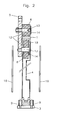
- FIG. 2 it is made of INCONEL due to the heating surface 16 indicated, has a rectangular shape, its length is greater than the worm wheel diameter, but its width is considerable smaller than the same.
- the central circle in the heating surface 16 indicates the substrate diameter and thus also the breakthrough in the two heating surfaces 16 through double-sided coating of the material flow for the substrate coating flows.
- the sources for the material flow can Cylinder cathodes / cathodes or plasma sources or others physical evaporation sources (PVD). material release by laser ablation is also used to form the material flow suitable.
- the frame of the storage consists of profile material made of heat-resistant Stainless steel, designated 1.4301, from here rectangular cross section.
- the lifting rod 11 and the support frame 3, the remaining three legs are assembled rectangular, screwed or welded.
- Hang from the lifting rod 11 the two bearing blocks 5, on which they are firmly attached, down.
- a bearing roller / disk 8 is seated in the end area Degussit A124, which is there on a precious metal, on each Bearing block 5 screwed axis (see Figure 2) rotating slides.
- the worm wheel 1 made of highly heat-resistant Stainless steel of the 1.4571 standard is symmetrical with its here trapezoidal inner groove 18 hanging on the two bearing rollers / discs 8.
- the bearing rollers 8 are in known technology to prevent seizure by means of fastening washer 14 and washer 12 localized (see Figure 2). Outside of Worm gear 1, the two counter bearings 6, one each a bearing block 5, and prevent the worm wheel 1 from jumping out.
- the two counter bearings 6 are like the two bearings 8 built on the worm wheel 1 rolls, they touch it Worm gear 1 not necessarily. Can or could but on the existing around the circumference of the worm wheel 1 Unroll the sprocket when it comes into contact.
- the frame part opposite the lifting rod 11 sits in the center the roller bearing 9 for the two bearing disks / rollers 8. It exists from the two vertical bearing sleeves 9 made of degussite AL24, which slidably on one in the support frame 3 Insert the screwed stainless steel axle of standard 1. 4301. The worm wheel 1 runs between the two sleeves 9 and is carried out with little play at all, so the substrate level guided.
- the substrate holder 15 is only indicated. The clamped The situation of the substrate is shown in FIG. 3.
- the substrate holder 15 is of the four here equally distributed in a circle Holding arms / tabs 17 held on the worm wheel 1 are firmly anchored.
- the circular disc-shaped substrate holder 15 is at the free end of the upper tab 17 in the figure firmly clamped over the holding finger, the rest is radial Expansion and contraction possible. That will be through the there indicated oblong holes in which the respective holding finger can move radially.
- the tabs 17, holding fingers and the substrate holder 15 are also made of high temperature resistant 1.4571 stainless steel.
Landscapes
- Physical Vapour Deposition (AREA)
- Container, Conveyance, Adherence, Positioning, Of Wafer (AREA)
- Furnace Charging Or Discharging (AREA)
- Coating Apparatus (AREA)
- Coating With Molten Metal (AREA)
- Motorcycle And Bicycle Frame (AREA)
- Window Of Vehicle (AREA)
Abstract
Description
- 1
- Schneckenrad, Substrathalterad
- 2
- Schnecke
- 3
- Trägerrahmen
- 4
- Substrat
- 5
- Lagerbock
- 6
- Gegenlager
- 7
- 7Lager
- 8
- Lagerscheibe
- 9
- Rollenlager, Lagerhülse
- 10
- Antrieb
- 11
- Hubstange
- 12
- Distanzscheibe, Unterlagsscheibe
- 13
- Gewindebolzen
- 14
- Befestigungsscheiben
- 15
- Substrathalter
- 16
- Heizflächen
- 17
- Streben, Laschen
- 18
- Nut, Innennut
Claims (9)
- Lagerung eines Substrathalterrades mit darin eingebautem/verankertem Substrathalter in einer Anlage zur Beschichtung eines zumindest einseitig beheizbaren Substrats, wobei das Substrathalterrad ein Schneckenrad ist, das über eine am Umfangsbereich eingreifende Schnecke angetrieben wird, bestehend aus:wobei der Substrathalter (15) über wenigstens drei am Schneckenrad (1) befestigte, radial nach innen ragende Streben (17) an einer davon unverrückbar und an den übrigen radial beweglich eingespannt ist.einer Hubstange (11), an der ein Trägerrahmen (3) hängend festgemacht ist,aus zwei an der Hubstange (11) hängend befestigten, fluchtenden Lagerböcken (5), die in den von der Hubstange (11) und dem Trägerrahmen (3) umspannten Innenbereich ragen und auf Abstand zueinander stehen,je zwei Lagerscheiben (8) aus hochwärmefestem, dielektrischen Material, wovon je eine im Endbereich der beiden Lagerböcke (5) drehbar gelagert ist, und sich beide Lagerscheiben (8) in einer gemeinsamen Drehebene drehen,zwei Gegenlagerrollen (6) aus hochwärmefestem, dielektrischen Material, je eines an einem der beiden Lagerböcke (5) oberhalb und in vorgegebenem Abstand zu der jeweilig darunter sitzenden Lagerscheibe (8), die in der gleichen Drehebene drehen,einem Rollenlager (9) aus zwei zylindrischen Lagerrollen (9) aus hochwärmefestem, dielektrischen Material, die stehend im Bodenteil des Trägerrahmens (3) drehbar gelagert sind und dies- und jenseits unter Abstand von mindestens der Dicke des Schneckenrades (1) sitzen, zwischen denen das auf den beiden Lagerscheiben (8) eingelegte Schneckenrad (1) hängend und geführt durchläuft,einem Lager (7) aus zwei kleinen Lagerböcken für die am Ende einer Antriebsstange (10) sitzenden Schnecke (2), die zwischen den beiden Lagerböcken (5) für das Schneckenrad (1) hängend an die Hubstange (11) fest angebracht sind, an deren jeweiligen freien Endbereich je eine Gleitlagerhülse (7) aus hochwärmefestem, dielektrischen Material sitzt, die parallel zu der Drehebene und fluchtend zueinander sitzen und die Antriebsstange (10) mit der Schnecke (2) derart führen, dass diese bei jeder Prozesstemperatur stets mehr oder weniger spielend in den Zahnkranz des eingehängten Schneckenrads (1) eingreift,
- Lagerung eines Substrathalterrads mit Substrathalter nach Anspruch 1,
dadurch gekennzeichnet, dass das hochwärmefeste, dielektrische Material Oxidkeramik ist. - Lagerung eines Schneckenrades mit Substrathalter nach Anspruch 2,
dadurch gekennzeichnet, dass das hochwärmefeste, dielektrische Material keramisches Al2O3 ist. - Lagerung eines Schneckenrades mit Substrathalter nach Anspruch 2,
dadurch gekennzeichnet, dass das hochwärmefeste, dielektrische Material kristallines Al2O3, Saphir, ist. - Lagerung eines Schneckenrades mit Substrathalter nach Anspruch 2,
dadurch gekennzeichnet, dass das hochwärmefeste, dielektrische Material SiO2, Quarzglas, ist. - Lagerung eines Schneckenrades mit Substrathalter nach Anspruch 2,
dadurch gekennzeichnet, dass das hochwärmefeste, dielektrische Material ZrO2 ist. - Lagerung eines Schneckenrades mit Substrathalter nach einem der Ansprüche 1 bis 6,
dadurch gekennzeichnet, dass das Schneckenrad (1) an der innenliegenden Mantelwand eine umlaufende, trapezförmige Nut (18) hat, an deren Boden die beiden Lagerscheiben (8) abrollen. - Lagerung eines Schneckenrades mit Substrathalter nach Anspruch 7,
dadurch gekennzeichnet, dass die nichtkeramischen Teile aus wärmefestem Edelstahl sind. - Lagerung eines Schneckenrades mit Substrathalter nach Anspruch 8,
dadurch gekennzeichnet, dass zumindest das Schneckenrad (1) samt Substrathalter (15) aus hochwärmefestem Edelstahl ist.
Applications Claiming Priority (2)
| Application Number | Priority Date | Filing Date | Title |
|---|---|---|---|
| DE10211827A DE10211827C1 (de) | 2002-03-16 | 2002-03-16 | Lagerung eines Substrathalterrades mit darin eingebautem/verankertem Substrathalter |
| DE10211827 | 2002-03-16 |
Publications (3)
| Publication Number | Publication Date |
|---|---|
| EP1345252A2 true EP1345252A2 (de) | 2003-09-17 |
| EP1345252A3 EP1345252A3 (de) | 2005-01-19 |
| EP1345252B1 EP1345252B1 (de) | 2007-03-07 |
Family
ID=27762967
Family Applications (1)
| Application Number | Title | Priority Date | Filing Date |
|---|---|---|---|
| EP03001509A Expired - Lifetime EP1345252B1 (de) | 2002-03-16 | 2003-01-23 | Lagerung eines Substrathalterrades mit darin eingebautem/verankertem Substrathalter |
Country Status (3)
| Country | Link |
|---|---|
| EP (1) | EP1345252B1 (de) |
| AT (1) | ATE356429T1 (de) |
| DE (2) | DE10211827C1 (de) |
Cited By (1)
| Publication number | Priority date | Publication date | Assignee | Title |
|---|---|---|---|---|
| CN114783940A (zh) * | 2022-05-20 | 2022-07-22 | 北京烁科中科信电子装备有限公司 | 一种晶片夹持装置 |
Families Citing this family (1)
| Publication number | Priority date | Publication date | Assignee | Title |
|---|---|---|---|---|
| DE102005045718B4 (de) | 2005-09-24 | 2009-06-25 | Applied Materials Gmbh & Co. Kg | Träger für ein Substrat |
Family Cites Families (4)
| Publication number | Priority date | Publication date | Assignee | Title |
|---|---|---|---|---|
| FR2429270A1 (fr) * | 1978-06-23 | 1980-01-18 | Mongodin Guy | Appareil pour realiser dans une enceinte sous vide, le depot d'une couche mince sur un substrat ou l'erosion de la surface d'une piece |
| DE19932338C1 (de) * | 1999-07-10 | 2000-12-14 | Karlsruhe Forschzent | Vorrichtung zum Rotieren eines mit keramischen und metallischen Substanzen zu beschichtenden Substrats in einem Prozeßraum |
| DE10032005B4 (de) * | 2000-06-30 | 2004-01-15 | Forschungszentrum Karlsruhe Gmbh | Waferhalterad mit einer Andrückvorrichtung in einer Waferbeschichtungsanlage |
| DE10037566C2 (de) * | 2000-08-02 | 2002-10-24 | Karlsruhe Forschzent | Substratheizung zum gleichzeitig beidseitigen Beheizen eines Wafers |
-
2002
- 2002-03-16 DE DE10211827A patent/DE10211827C1/de not_active Expired - Fee Related
-
2003
- 2003-01-23 EP EP03001509A patent/EP1345252B1/de not_active Expired - Lifetime
- 2003-01-23 AT AT03001509T patent/ATE356429T1/de not_active IP Right Cessation
- 2003-01-23 DE DE50306711T patent/DE50306711D1/de not_active Expired - Fee Related
Cited By (1)
| Publication number | Priority date | Publication date | Assignee | Title |
|---|---|---|---|---|
| CN114783940A (zh) * | 2022-05-20 | 2022-07-22 | 北京烁科中科信电子装备有限公司 | 一种晶片夹持装置 |
Also Published As
| Publication number | Publication date |
|---|---|
| EP1345252B1 (de) | 2007-03-07 |
| EP1345252A3 (de) | 2005-01-19 |
| ATE356429T1 (de) | 2007-03-15 |
| DE10211827C1 (de) | 2003-10-30 |
| DE50306711D1 (de) | 2007-04-19 |
Similar Documents
| Publication | Publication Date | Title |
|---|---|---|
| EP3684529B1 (de) | Bauzylinder für eine maschine zur schichtweisen fertigung dreidimensionaler objekte, mit vermindertem temperaturgradienten | |
| DE69731199T2 (de) | Verfahren und einrichtung zur berührungslose behandlung eines scheiben förmiges halbleitersubstrats | |
| DE19649508B4 (de) | Halter für Halbleiterplatten | |
| EP2165006B1 (de) | Vorrichtung zum beschichten von auf einem suszeptor angeordneten substraten | |
| DE102015211538A1 (de) | Bauzylinder-Anordnung für eine Maschine zur schichtweisen Fertigung dreidimensionaler Objekte | |
| DE112013001929T5 (de) | Kantenring für eine Abscheidungskammer | |
| DE112017001577T5 (de) | Suszeptorträger | |
| DE60015788T2 (de) | Kompaktes schieberventil | |
| DE19743922C1 (de) | Verfahren zur CVD-Oberflächenbeschichtung und CVD-Reaktorsystem | |
| DE10236896B4 (de) | Vorrichtung und Verfahren zum thermischen Behandeln von Halbleiterwafern | |
| EP1223231B1 (de) | Vorrichtung zur Aufnahme eines optischen Elementes aus einem kristallinen Material während eines Aufdampfprozesses | |
| DE102007048564A1 (de) | Vorrichtung für eine Bestrahlungseinheit | |
| DE10211827C1 (de) | Lagerung eines Substrathalterrades mit darin eingebautem/verankertem Substrathalter | |
| DE102019131046A1 (de) | Prozessierkammer und Verfahren | |
| DE102004039443B4 (de) | Verfahren zum thermischen Behandeln von scheibenförmigen Substraten | |
| DE69935858T2 (de) | Verfahren und vorrichtung zur behandlung von scheiben | |
| EP1393355A2 (de) | Vorrichtung zur aufnahme von scheibenförmigen objekten | |
| DE19932338C1 (de) | Vorrichtung zum Rotieren eines mit keramischen und metallischen Substanzen zu beschichtenden Substrats in einem Prozeßraum | |
| DE2635007A1 (de) | Vakuumanlage zum behandeln eines gutes, insbesondere vakuumaufdampfanlage | |
| DE10122070B4 (de) | Kathodenzerstäubungskammer zum Aufbringen von Material auf der Oberfläche einer in der Kammer befindlichen Halbleiterscheibe | |
| DE102015105844B4 (de) | Verschlusseinrichtung, Pyrometer-Anordnung und Vakuum-Substratbehandlungsanlage | |
| DE2612606C3 (de) | Vorrichtung zur Aufhetzung insbesondere großflächiger, für Werkstoffuntersuchungen geeigneter Elektroden | |
| DE102024126444A1 (de) | CVD-Reaktor | |
| EP0107255B1 (de) | Küvette für die Atomabsorptionsspektrometrie | |
| DE102005059850A1 (de) | Vorrichtung zum Reinigen und Trocknen von Wafern |
Legal Events
| Date | Code | Title | Description |
|---|---|---|---|
| PUAI | Public reference made under article 153(3) epc to a published international application that has entered the european phase |
Free format text: ORIGINAL CODE: 0009012 |
|
| AK | Designated contracting states |
Kind code of ref document: A2 Designated state(s): AT BE BG CH CY CZ DE DK EE ES FI FR GB GR HU IE IT LI LU MC NL PT SE SI SK TR |
|
| AX | Request for extension of the european patent |
Extension state: AL LT LV MK RO |
|
| PUAL | Search report despatched |
Free format text: ORIGINAL CODE: 0009013 |
|
| AK | Designated contracting states |
Kind code of ref document: A3 Designated state(s): AT BE BG CH CY CZ DE DK EE ES FI FR GB GR HU IE IT LI LU MC NL PT SE SI SK TR |
|
| AX | Request for extension of the european patent |
Extension state: AL LT LV MK RO |
|
| 17P | Request for examination filed |
Effective date: 20050521 |
|
| AKX | Designation fees paid |
Designated state(s): AT BE BG CH CY CZ DE DK EE ES FI FR GB GR HU IE IT LI LU MC NL PT SE SI SK TR |
|
| GRAP | Despatch of communication of intention to grant a patent |
Free format text: ORIGINAL CODE: EPIDOSNIGR1 |
|
| GRAS | Grant fee paid |
Free format text: ORIGINAL CODE: EPIDOSNIGR3 |
|
| GRAA | (expected) grant |
Free format text: ORIGINAL CODE: 0009210 |
|
| AK | Designated contracting states |
Kind code of ref document: B1 Designated state(s): AT BE BG CH CY CZ DE DK EE ES FI FR GB GR HU IE IT LI LU MC NL PT SE SI SK TR |
|
| PG25 | Lapsed in a contracting state [announced via postgrant information from national office to epo] |
Ref country code: FI Free format text: LAPSE BECAUSE OF FAILURE TO SUBMIT A TRANSLATION OF THE DESCRIPTION OR TO PAY THE FEE WITHIN THE PRESCRIBED TIME-LIMIT Effective date: 20070307 Ref country code: NL Free format text: LAPSE BECAUSE OF FAILURE TO SUBMIT A TRANSLATION OF THE DESCRIPTION OR TO PAY THE FEE WITHIN THE PRESCRIBED TIME-LIMIT Effective date: 20070307 Ref country code: IE Free format text: LAPSE BECAUSE OF FAILURE TO SUBMIT A TRANSLATION OF THE DESCRIPTION OR TO PAY THE FEE WITHIN THE PRESCRIBED TIME-LIMIT Effective date: 20070307 Ref country code: SI Free format text: LAPSE BECAUSE OF FAILURE TO SUBMIT A TRANSLATION OF THE DESCRIPTION OR TO PAY THE FEE WITHIN THE PRESCRIBED TIME-LIMIT Effective date: 20070307 |
|
| REG | Reference to a national code |
Ref country code: GB Ref legal event code: FG4D Free format text: NOT ENGLISH |
|
| REG | Reference to a national code |
Ref country code: CH Ref legal event code: EP |
|
| REF | Corresponds to: |
Ref document number: 50306711 Country of ref document: DE Date of ref document: 20070419 Kind code of ref document: P |
|
| REG | Reference to a national code |
Ref country code: IE Ref legal event code: FG4D Free format text: LANGUAGE OF EP DOCUMENT: GERMAN |
|
| PG25 | Lapsed in a contracting state [announced via postgrant information from national office to epo] |
Ref country code: SE Free format text: LAPSE BECAUSE OF FAILURE TO SUBMIT A TRANSLATION OF THE DESCRIPTION OR TO PAY THE FEE WITHIN THE PRESCRIBED TIME-LIMIT Effective date: 20070607 |
|
| PG25 | Lapsed in a contracting state [announced via postgrant information from national office to epo] |
Ref country code: ES Free format text: LAPSE BECAUSE OF FAILURE TO SUBMIT A TRANSLATION OF THE DESCRIPTION OR TO PAY THE FEE WITHIN THE PRESCRIBED TIME-LIMIT Effective date: 20070618 |
|
| PG25 | Lapsed in a contracting state [announced via postgrant information from national office to epo] |
Ref country code: PT Free format text: LAPSE BECAUSE OF FAILURE TO SUBMIT A TRANSLATION OF THE DESCRIPTION OR TO PAY THE FEE WITHIN THE PRESCRIBED TIME-LIMIT Effective date: 20070807 |
|
| NLV1 | Nl: lapsed or annulled due to failure to fulfill the requirements of art. 29p and 29m of the patents act | ||
| GBV | Gb: ep patent (uk) treated as always having been void in accordance with gb section 77(7)/1977 [no translation filed] |
Effective date: 20070307 |
|
| REG | Reference to a national code |
Ref country code: IE Ref legal event code: FD4D |
|
| EN | Fr: translation not filed | ||
| PG25 | Lapsed in a contracting state [announced via postgrant information from national office to epo] |
Ref country code: GB Free format text: LAPSE BECAUSE OF FAILURE TO SUBMIT A TRANSLATION OF THE DESCRIPTION OR TO PAY THE FEE WITHIN THE PRESCRIBED TIME-LIMIT Effective date: 20070307 Ref country code: SK Free format text: LAPSE BECAUSE OF FAILURE TO SUBMIT A TRANSLATION OF THE DESCRIPTION OR TO PAY THE FEE WITHIN THE PRESCRIBED TIME-LIMIT Effective date: 20070307 |
|
| PG25 | Lapsed in a contracting state [announced via postgrant information from national office to epo] |
Ref country code: CZ Free format text: LAPSE BECAUSE OF FAILURE TO SUBMIT A TRANSLATION OF THE DESCRIPTION OR TO PAY THE FEE WITHIN THE PRESCRIBED TIME-LIMIT Effective date: 20070307 |
|
| PLBE | No opposition filed within time limit |
Free format text: ORIGINAL CODE: 0009261 |
|
| STAA | Information on the status of an ep patent application or granted ep patent |
Free format text: STATUS: NO OPPOSITION FILED WITHIN TIME LIMIT |
|
| PG25 | Lapsed in a contracting state [announced via postgrant information from national office to epo] |
Ref country code: DK Free format text: LAPSE BECAUSE OF FAILURE TO SUBMIT A TRANSLATION OF THE DESCRIPTION OR TO PAY THE FEE WITHIN THE PRESCRIBED TIME-LIMIT Effective date: 20070307 |
|
| 26N | No opposition filed |
Effective date: 20071210 |
|
| PG25 | Lapsed in a contracting state [announced via postgrant information from national office to epo] |
Ref country code: GR Free format text: LAPSE BECAUSE OF FAILURE TO SUBMIT A TRANSLATION OF THE DESCRIPTION OR TO PAY THE FEE WITHIN THE PRESCRIBED TIME-LIMIT Effective date: 20070608 Ref country code: IT Free format text: LAPSE BECAUSE OF FAILURE TO SUBMIT A TRANSLATION OF THE DESCRIPTION OR TO PAY THE FEE WITHIN THE PRESCRIBED TIME-LIMIT Effective date: 20070307 Ref country code: FR Free format text: LAPSE BECAUSE OF FAILURE TO SUBMIT A TRANSLATION OF THE DESCRIPTION OR TO PAY THE FEE WITHIN THE PRESCRIBED TIME-LIMIT Effective date: 20071026 |
|
| BERE | Be: lapsed |
Owner name: FORSCHUNGSZENTRUM KARLSRUHE G.M.B.H. Effective date: 20080131 |
|
| PG25 | Lapsed in a contracting state [announced via postgrant information from national office to epo] |
Ref country code: MC Free format text: LAPSE BECAUSE OF NON-PAYMENT OF DUE FEES Effective date: 20080131 |
|
| REG | Reference to a national code |
Ref country code: CH Ref legal event code: PL |
|
| PG25 | Lapsed in a contracting state [announced via postgrant information from national office to epo] |
Ref country code: CH Free format text: LAPSE BECAUSE OF NON-PAYMENT OF DUE FEES Effective date: 20080131 Ref country code: DE Free format text: LAPSE BECAUSE OF NON-PAYMENT OF DUE FEES Effective date: 20080801 Ref country code: LI Free format text: LAPSE BECAUSE OF NON-PAYMENT OF DUE FEES Effective date: 20080131 |
|
| PG25 | Lapsed in a contracting state [announced via postgrant information from national office to epo] |
Ref country code: FR Free format text: LAPSE BECAUSE OF FAILURE TO SUBMIT A TRANSLATION OF THE DESCRIPTION OR TO PAY THE FEE WITHIN THE PRESCRIBED TIME-LIMIT Effective date: 20070307 |
|
| PG25 | Lapsed in a contracting state [announced via postgrant information from national office to epo] |
Ref country code: EE Free format text: LAPSE BECAUSE OF FAILURE TO SUBMIT A TRANSLATION OF THE DESCRIPTION OR TO PAY THE FEE WITHIN THE PRESCRIBED TIME-LIMIT Effective date: 20070307 |
|
| PG25 | Lapsed in a contracting state [announced via postgrant information from national office to epo] |
Ref country code: BE Free format text: LAPSE BECAUSE OF NON-PAYMENT OF DUE FEES Effective date: 20080131 |
|
| PG25 | Lapsed in a contracting state [announced via postgrant information from national office to epo] |
Ref country code: AT Free format text: LAPSE BECAUSE OF NON-PAYMENT OF DUE FEES Effective date: 20080123 |
|
| PG25 | Lapsed in a contracting state [announced via postgrant information from national office to epo] |
Ref country code: CY Free format text: LAPSE BECAUSE OF FAILURE TO SUBMIT A TRANSLATION OF THE DESCRIPTION OR TO PAY THE FEE WITHIN THE PRESCRIBED TIME-LIMIT Effective date: 20070307 |
|
| PG25 | Lapsed in a contracting state [announced via postgrant information from national office to epo] |
Ref country code: BG Free format text: LAPSE BECAUSE OF FAILURE TO SUBMIT A TRANSLATION OF THE DESCRIPTION OR TO PAY THE FEE WITHIN THE PRESCRIBED TIME-LIMIT Effective date: 20070607 |
|
| PG25 | Lapsed in a contracting state [announced via postgrant information from national office to epo] |
Ref country code: LU Free format text: LAPSE BECAUSE OF NON-PAYMENT OF DUE FEES Effective date: 20080123 Ref country code: HU Free format text: LAPSE BECAUSE OF FAILURE TO SUBMIT A TRANSLATION OF THE DESCRIPTION OR TO PAY THE FEE WITHIN THE PRESCRIBED TIME-LIMIT Effective date: 20070908 |
|
| PG25 | Lapsed in a contracting state [announced via postgrant information from national office to epo] |
Ref country code: TR Free format text: LAPSE BECAUSE OF FAILURE TO SUBMIT A TRANSLATION OF THE DESCRIPTION OR TO PAY THE FEE WITHIN THE PRESCRIBED TIME-LIMIT Effective date: 20070307 |