EP1345205A1 - Verfahren zur Beschleuinigung der Bildwiedergabe von auf Bildpunkt-Teilkomponeneten abgebildeten Bildern - Google Patents
Verfahren zur Beschleuinigung der Bildwiedergabe von auf Bildpunkt-Teilkomponeneten abgebildeten Bildern Download PDFInfo
- Publication number
- EP1345205A1 EP1345205A1 EP03005428A EP03005428A EP1345205A1 EP 1345205 A1 EP1345205 A1 EP 1345205A1 EP 03005428 A EP03005428 A EP 03005428A EP 03005428 A EP03005428 A EP 03005428A EP 1345205 A1 EP1345205 A1 EP 1345205A1
- Authority
- EP
- European Patent Office
- Prior art keywords
- sub
- component
- character
- pixel
- act
- Prior art date
- Legal status (The legal status is an assumption and is not a legal conclusion. Google has not performed a legal analysis and makes no representation as to the accuracy of the status listed.)
- Ceased
Links
- 238000009877 rendering Methods 0.000 title claims abstract description 45
- 230000001133 acceleration Effects 0.000 title abstract description 3
- 238000000034 method Methods 0.000 claims description 41
- 238000002156 mixing Methods 0.000 claims description 21
- 238000012545 processing Methods 0.000 claims description 19
- 239000000872 buffer Substances 0.000 claims description 15
- 238000006243 chemical reaction Methods 0.000 claims description 9
- 230000006978 adaptation Effects 0.000 claims description 7
- 239000007787 solid Substances 0.000 claims description 6
- 238000004590 computer program Methods 0.000 claims description 4
- 230000006870 function Effects 0.000 description 31
- 230000003287 optical effect Effects 0.000 description 8
- 238000004364 calculation method Methods 0.000 description 7
- 239000003086 colorant Substances 0.000 description 7
- 230000000694 effects Effects 0.000 description 7
- 238000005516 engineering process Methods 0.000 description 7
- 238000012935 Averaging Methods 0.000 description 6
- 238000007796 conventional method Methods 0.000 description 5
- 230000009466 transformation Effects 0.000 description 5
- 230000008901 benefit Effects 0.000 description 4
- 238000004891 communication Methods 0.000 description 4
- 230000008569 process Effects 0.000 description 4
- 239000008186 active pharmaceutical agent Substances 0.000 description 3
- 238000006073 displacement reaction Methods 0.000 description 3
- 230000005055 memory storage Effects 0.000 description 3
- 230000006855 networking Effects 0.000 description 3
- 230000000007 visual effect Effects 0.000 description 3
- 238000003384 imaging method Methods 0.000 description 2
- 238000012986 modification Methods 0.000 description 2
- 230000004048 modification Effects 0.000 description 2
- 230000002093 peripheral effect Effects 0.000 description 2
- 238000005070 sampling Methods 0.000 description 2
- 238000000844 transformation Methods 0.000 description 2
- PXFBZOLANLWPMH-UHFFFAOYSA-N 16-Epiaffinine Natural products C1C(C2=CC=CC=C2N2)=C2C(=O)CC2C(=CC)CN(C)C1C2CO PXFBZOLANLWPMH-UHFFFAOYSA-N 0.000 description 1
- 239000000654 additive Substances 0.000 description 1
- 230000000996 additive effect Effects 0.000 description 1
- 238000004883 computer application Methods 0.000 description 1
- 230000007423 decrease Effects 0.000 description 1
- 238000013461 design Methods 0.000 description 1
- 238000007667 floating Methods 0.000 description 1
- 230000008571 general function Effects 0.000 description 1
- 239000004973 liquid crystal related substance Substances 0.000 description 1
- 239000000203 mixture Substances 0.000 description 1
- 230000004044 response Effects 0.000 description 1
- 238000012546 transfer Methods 0.000 description 1
Images


Classifications
-
- G—PHYSICS
- G06—COMPUTING; CALCULATING OR COUNTING
- G06T—IMAGE DATA PROCESSING OR GENERATION, IN GENERAL
- G06T1/00—General purpose image data processing
-
- G—PHYSICS
- G09—EDUCATION; CRYPTOGRAPHY; DISPLAY; ADVERTISING; SEALS
- G09G—ARRANGEMENTS OR CIRCUITS FOR CONTROL OF INDICATING DEVICES USING STATIC MEANS TO PRESENT VARIABLE INFORMATION
- G09G3/00—Control arrangements or circuits, of interest only in connection with visual indicators other than cathode-ray tubes
- G09G3/20—Control arrangements or circuits, of interest only in connection with visual indicators other than cathode-ray tubes for presentation of an assembly of a number of characters, e.g. a page, by composing the assembly by combination of individual elements arranged in a matrix no fixed position being assigned to or needed to be assigned to the individual characters or partial characters
- G09G3/34—Control arrangements or circuits, of interest only in connection with visual indicators other than cathode-ray tubes for presentation of an assembly of a number of characters, e.g. a page, by composing the assembly by combination of individual elements arranged in a matrix no fixed position being assigned to or needed to be assigned to the individual characters or partial characters by control of light from an independent source
- G09G3/36—Control arrangements or circuits, of interest only in connection with visual indicators other than cathode-ray tubes for presentation of an assembly of a number of characters, e.g. a page, by composing the assembly by combination of individual elements arranged in a matrix no fixed position being assigned to or needed to be assigned to the individual characters or partial characters by control of light from an independent source using liquid crystals
- G09G3/3607—Control arrangements or circuits, of interest only in connection with visual indicators other than cathode-ray tubes for presentation of an assembly of a number of characters, e.g. a page, by composing the assembly by combination of individual elements arranged in a matrix no fixed position being assigned to or needed to be assigned to the individual characters or partial characters by control of light from an independent source using liquid crystals for displaying colours or for displaying grey scales with a specific pixel layout, e.g. using sub-pixels
-
- G—PHYSICS
- G09—EDUCATION; CRYPTOGRAPHY; DISPLAY; ADVERTISING; SEALS
- G09G—ARRANGEMENTS OR CIRCUITS FOR CONTROL OF INDICATING DEVICES USING STATIC MEANS TO PRESENT VARIABLE INFORMATION
- G09G5/00—Control arrangements or circuits for visual indicators common to cathode-ray tube indicators and other visual indicators
- G09G5/22—Control arrangements or circuits for visual indicators common to cathode-ray tube indicators and other visual indicators characterised by the display of characters or indicia using display control signals derived from coded signals representing the characters or indicia, e.g. with a character-code memory
- G09G5/24—Generation of individual character patterns
- G09G5/28—Generation of individual character patterns for enhancement of character form, e.g. smoothing
-
- G—PHYSICS
- G09—EDUCATION; CRYPTOGRAPHY; DISPLAY; ADVERTISING; SEALS
- G09G—ARRANGEMENTS OR CIRCUITS FOR CONTROL OF INDICATING DEVICES USING STATIC MEANS TO PRESENT VARIABLE INFORMATION
- G09G2300/00—Aspects of the constitution of display devices
- G09G2300/04—Structural and physical details of display devices
- G09G2300/0439—Pixel structures
- G09G2300/0443—Pixel structures with several sub-pixels for the same colour in a pixel, not specifically used to display gradations
-
- G—PHYSICS
- G09—EDUCATION; CRYPTOGRAPHY; DISPLAY; ADVERTISING; SEALS
- G09G—ARRANGEMENTS OR CIRCUITS FOR CONTROL OF INDICATING DEVICES USING STATIC MEANS TO PRESENT VARIABLE INFORMATION
- G09G2340/00—Aspects of display data processing
- G09G2340/04—Changes in size, position or resolution of an image
- G09G2340/0407—Resolution change, inclusive of the use of different resolutions for different screen areas
- G09G2340/0421—Horizontal resolution change
-
- G—PHYSICS
- G09—EDUCATION; CRYPTOGRAPHY; DISPLAY; ADVERTISING; SEALS
- G09G—ARRANGEMENTS OR CIRCUITS FOR CONTROL OF INDICATING DEVICES USING STATIC MEANS TO PRESENT VARIABLE INFORMATION
- G09G2340/00—Aspects of display data processing
- G09G2340/04—Changes in size, position or resolution of an image
- G09G2340/0457—Improvement of perceived resolution by subpixel rendering
-
- G—PHYSICS
- G09—EDUCATION; CRYPTOGRAPHY; DISPLAY; ADVERTISING; SEALS
- G09G—ARRANGEMENTS OR CIRCUITS FOR CONTROL OF INDICATING DEVICES USING STATIC MEANS TO PRESENT VARIABLE INFORMATION
- G09G3/00—Control arrangements or circuits, of interest only in connection with visual indicators other than cathode-ray tubes
- G09G3/20—Control arrangements or circuits, of interest only in connection with visual indicators other than cathode-ray tubes for presentation of an assembly of a number of characters, e.g. a page, by composing the assembly by combination of individual elements arranged in a matrix no fixed position being assigned to or needed to be assigned to the individual characters or partial characters
- G09G3/2007—Display of intermediate tones
- G09G3/2074—Display of intermediate tones using sub-pixels
-
- G—PHYSICS
- G09—EDUCATION; CRYPTOGRAPHY; DISPLAY; ADVERTISING; SEALS
- G09G—ARRANGEMENTS OR CIRCUITS FOR CONTROL OF INDICATING DEVICES USING STATIC MEANS TO PRESENT VARIABLE INFORMATION
- G09G5/00—Control arrangements or circuits for visual indicators common to cathode-ray tube indicators and other visual indicators
- G09G5/22—Control arrangements or circuits for visual indicators common to cathode-ray tube indicators and other visual indicators characterised by the display of characters or indicia using display control signals derived from coded signals representing the characters or indicia, e.g. with a character-code memory
- G09G5/24—Generation of individual character patterns
Definitions
- the present invention relates to methods and systems for displaying images, and more particularly, to methods and systems for efficiently rendering and animating characters using a hardware graphics unit when treating each pixel sub-component as an independent luminance intensity source.
- Display devices are commonly used to render images to a human viewer.
- the effective rendering of images to a human viewer is fundamental to television and many types of computing technology. Accordingly, display devices are associated with televisions and many computing systems.
- Images are rendered to a viewer using thousands of pixels distributed in a grid pattern on a display device.
- the color and/or intensity values of each of the pixels may be adjusted in order to form the desired image.
- the color that a user perceives as emitting from a single pixel is actually represented by multiple displaced color components.
- a RGB display device there is one light source that emits exclusively the color red. Another separate light source exclusively emits the color green. Another separate light source exclusively emit the color blue. These light sources are called herein the red, green, and blue color components of a pixel.
- these color components are spatially offset.
- the spatial offset is sufficiently small that a typical human user is unable to distinguish the individual color components of a pixel.
- the light from the color components blends together so that the pixel is perceived to have a single color.
- This single pixel color may be adjusted by adjusting the intensity of the red, green, and blue color components of the pixel such that the pixel may achieve a wide variety of perceived colors.
- White may be achieved by having maximum intensities in the red, green, and blue color components.
- black may be achieved by having minimum intensities in the red, green, and blue color components.
- FIG. 1 illustrates a conventional portable computer 100, which comprises a housing 101, a disk drive 102, a keyboard 103, and a display 104.
- the display 104 may be, for example, an LCD display.
- each pixel on a color LCD display is represented by a single pixel element, which usually comprises three non-square pixel subcomponents such as a red pixel sub-component, a green pixel sub-component, and a blue pixel sub-component.
- a set of RGB pixel sub-components together makes up a single pixel element.
- Conventional LCD displays comprise a series of RGB pixel sub-components that are commonly arranged to form stripes along the display. The RGB stripes normally run the entire length of the display in one direction. The resulting RGB stripes are sometimes referred to as "RGB striping".
- RGB striping Common LCD monitors used for computer applications, which are wider than they are tall, tend to have RGB stripes running in the vertical direction.
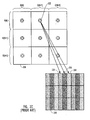
- Figure 2A illustrates a known LCD screen 200 comprising a plurality of rows (R1-R12) and columns (C1-C16) that may be represented on the display 104. Each row/column intersection forms a square (or a rectangle that is almost the same in height as in width), which represents one pixel element.
- Figure 2B illustrates the upper left hand portion of the known display 200 in greater detail.
- each pixel element (e.g., the [R2, C1] pixel element), comprises three distinct sub-components, a red sub-component 206, a green sub-component 207 and a blue sub-component 208.
- Each known pixel sub-component 206, 207, 208 is approximately one third the width of a pixel while being equal, in height, to the height of a pixel.
- one known arrangement of RGB pixel sub-components 206, 207, 208 form what appear to be vertical color stripes down the display 200. Accordingly, the arrangement of 1/3 width color sub-components 206, 207, 208, in the known manner illustrated in Figs.
- LCDs are manufactured with pixel sub-components arranged in several additional patterns including, e.g., zig-zags and a delta pattern common in camcorder view finders, or in horizontal striping in which the RGB pixel sub-components each have one third of the entire pixel height, and have the same width as the pixel.
- additional patterns including, e.g., zig-zags and a delta pattern common in camcorder view finders, or in horizontal striping in which the RGB pixel sub-components each have one third of the entire pixel height, and have the same width as the pixel.
- each set of pixel sub-components for a pixel element is treated as a single pixel unit. Accordingly, in known systems luminous intensity values for all the pixel sub-components of a pixel element are generated from the same portion of an image.
- the image represented by the grid 220 illustrated in Figure 2C each square represents an area of an image which is to be represented by a single pixel element including a red, green and blue pixel sub-component of the corresponding square of the grid 220.
- a shaded circle is used to represent a single image sample from which luminous intensity values are generated. Note how a single sample 222 of the image 220 is used in known systems to generate the luminous intensity values for each of the red, green, and blue pixel sub-components 232, 233, 234. Thus, in known systems, the RGB pixel sub-components are generally used as a group to generate a single colored pixel corresponding to a single sample of the image to be represented.
- each pixel sub-component group effectively adds together to create the effect of a single color whose hue, saturation, and intensity depends on the value of each of the three pixel sub-components.
- each pixel sub-component has a potential intensity of between 0 and 255. If all three pixel sub-components are given 255 intensity, the eye perceives the pixel as being white. However, if all three pixel sub-components are given a value of 0, the eye perceives a black pixel.
- Text characters represent one type of image which is particularly difficult to accurately display given typical flat panel display resolutions of 72 or 96 dots (pixels) per inch (dpi). Such display resolutions are far lower than the 600 dpi supported by most printers and the even higher resolutions found in most commercially printed text such as books and magazines. Accordingly, smaller visual objects such as text characters may appear coarse when the image resolution is limited to the pixel resolution.
- the Hill et al. patent describes a technology that treats each pixel sub-component as a separate independent luminous intensity source. This contrasts with the conventional technique of treating the set of RGB pixel sub-components for a given pixel as being a single luminous intensity source.
- the Hill et al. patent describes that each image sample is used to generate the luminance intensity value for a single pixel sub-component. This contrasts with the conventional technique of generating all of the pixel sub-component values for a given pixel using a single image sample.
- the technology described in the Hill et al. patent allows for a display device with RGB vertical striping to have an effective horizontal resolution that is up to three times greater than the horizontal pixel resolution.
- Figure 3 illustrates a general functional flow that may be implemented by the computer 100 in order to render and rasterize text images on the display 104 using the technology described in the Hill et al. patent.
- an application running on the computer 100 instructs the computer's operating system that the letter i having a given font and point size, is to be rendered and rasterized on the display 104.
- the left column of Figure 3 labeled under the heading "Functional Flow" illustrates the general functions that are implemented to render a text character using this technology.
- the right column of Figure 3 under the heading "Example” represents the state of the character i after the corresponding function to the left is implemented.
- the process begins with a character description 301, which describes the form of a character. This may be accomplished by using vector graphics, lines, points and curves, from which a high-resolution digital representation of the character may be derived.
- a typical operating system will have a number of different character descriptions corresponding to each character of each font.
- Element 311 shows the visual representation of the character description for the letter i .
- the operating system also has access to background color and layout information for the images that are currently being displayed, and brush color and transparency information that are to be applied to the text character during rendering.
- operation proceeds to scaling 302 where non-square scaling is performed as a function of the direction and/or number of pixel sub-components included in each pixel element.
- the vertical direction of the character described in the character description is scaled so as to meet the height requirements for the point size specified by the application.
- the horizontal direction is scaled at a rate three times greater than in the vertical direction. This allows for subsequent image processing operations to take advantage of the higher horizontal degree of resolution that can be achieved by using individual pixel sub-components as independent luminous intensity sources in a vertically striped display.
- the scaling in the horizontal direction is at a relative rate that is related to the number of pixel sub-components in a given pixel.
- the RGB vertical striping display there are three pixel sub-components in any given pixel. Accordingly, in the simplest case, scaling in the horizontal direction occurs at a rate approximately three times the rate of scaling in the vertical direction. This scaling may occur by manipulating the character description as appropriate.
- Element 312 shows the state of the character represented by the scaled character description. Note that in the illustrated case where the height of the character remains the same, the letter i is stretched horizontally by a factor of approximately three during scaling.
- hinting 303 After scaling 302, operation proceeds to hinting 303.
- the term "grid-fitting" is sometimes used to describe the hinting process. Hinting involves the alignment of a scaled character within a grid. It also involves the distorting of image outlines so that the image better conforms to the shape of the grid. The grid is determined as a function of the physical size of a display device's pixel elements. Unlike earlier techniques that failed to take into consideration pixel sub-component boundaries during hinting, hinting 303 treats pixel sub-component boundaries as boundaries along which characters can and should be aligned or boundaries to which the outline of a character should be adjusted.
- the hinting process involves aligning the scaled representation of a character within the grid along or within pixel and pixel sub-component boundaries in a manner intended to optimize the accurate display of the character using the available pixel sub-components. In many cases, this involves aligning the left edge of a character stem with a left pixel or sub-pixel component boundary and aligning the bottom of the character's base along a pixel or pixel sub-component boundary.
- the scaled image 312 is first placed over a grid pattern as represented by grid layout 313A.
- the grid pattern is shown for four columns of pixels labeled C1 through C4 from left to right, and six rows of pixels labeled R1 through R6 from top to bottom.
- boundaries between pixel sub-components are represented by dashed lines except where there is also a boundary between pixels.
- the pixel boundaries are represented as solid lines. Note that each pixel sub-components has a heading R, G, or B representing whether the column represents the red, green, or blue color, respectively.
- the left edge of the scaled i character is aligned along the R/G pixel sub-component boundary so that the left edge of the stem of the hinted character 312' has a green left edge to promote legibility.
- the shape of the character is also adjusted as well as the position of the character on the grid. Character spacing adjustments are also made.
- scan conversion 304 involves the conversion of the scaled geometry representing a character into a bitmap image.
- Conventional scan conversion operations treat pixels as individual units into which a corresponding portion of the scaled image can be mapped.
- each pixel sub-component is treated as a separate luminous intensity component into which a separate portion of the scaled image can be mapped.
- bitmap image 314 Note how each pixel sub-component of bitmap image columns C1-C4 is determined from a different segment of the corresponding columns of the scaled hinted image 313B. This contrasts with the conventional technique of having all three pixel sub-component values for a given pixel generated from a single portion of an image.
- bitmap image 314 comprises a 2/3 pixel width stem with a left edge aligned along a red/green pixel boundary. Notice also that a dot that is 2/3 of a pixel in width is used.
- Conventional text imaging techniques that treated each pixel as a single luminous intensity component would have resulted in a less accurate image having a stem a full pixel wide and a dot a full pixel in size.
- bitmap image 314 Once the bitmap representation of the text (i.e., bitmap image 314) is generated during scan conversion 304, it may be output to a display adapter or processed further to perform color processing operations and/or color adjustments to enhance image quality. While the human eye is much more sensitive to luminance edges as opposed to image color (chrominance) edges, treating the RGB pixel sub-components as independent luminous intensity elements for purposes of image rendering can result in undesired color fringing effects. If, for instance, you remove red from an RGB set, a color fringing effect of cyan, the additive of green and blue, is likely to result.
- bitmap image 314 may be supplied to color processing 305, where image processing is performed to determine how far away from the desired brush color the bitmap image has strayed. If portions of the bitmap image have strayed more than a preselected amount from the desired brush color, adjustments in the intensity values of pixel sub-components are applied until the image portions are brought within an acceptable range of an average between the brush and background colors.
- the bitmap image 314 is then applied via a blending operation to the existing background image.
- the red, green, and blue color intensities be given by glyph.r, glyph.g, and glyph.b.
- a glyph is a term that represent the shape of the character with respect to that pixel sub-components of the given pixel.
- the three value vector of red, green, and blue color components is represented by the vector glyph.rgb.
- the brush or foreground color components are represented by a similar vector brush.rgb.
- a scalar value of the transparency of the brush at each color component is given by the vector brusha.rgb.
- the background color for that pixel is given by a three value vector dst.rgb.
- DST.rgb DST.rgb+(brush.rgb-dst.rgb)*glyph.rgb*brusha.rgb
- a bit-map representation of the sub-component-oriented character is generated by using a single image sample to generate each pixel sub-component.
- a graphics unit accesses a character representation that describes the outline of the character. Then, the character representation is overscaled and conceptually placed on a grid. Each grid position corresponds to a sampling point as well as to a particular pixel sub-component. Hinting may occur by adjusting the shape of the character by considering the sub-component boundaries, not just the pixel boundaries.
- Scan conversion is performed to generate a bit map representation of the character based on the position of the character on the grid. Then, color compensation occurs to compensate for color fringing effects.
- the character is rendered by interfacing with a hardware graphics unit that performs the final rendering and animation of the character.
- the rendering and animation speed is increased substantially over the prior method of performing rendering and animating in software.
- the bit map representation of the character, as well as the bit map representations or the brush and/or the background are adjusted and then a non-conventional sequence of function calls are issued to the hardware graphics unit to cause the hardware graphics unit to render the character by blending the character, scaling the character, and/or rotating the character on a background.
- the principles of the present invention provide for more efficient rendering and animation of characters that have pixel sub-component values that were generated from individual sample points.
- FIG. 1 illustrates a convention portable computer in accordance with the prior art.
- Figure 2A illustrates a vertically-striped display comprising 12 rows and 16 columns of pixels, each pixel having a red, green, and blue pixel sub-component horizontally placed next to each other to form vertical striping in accordance with the prior art.
- Figure 2B illustrates the upper left-hand portion of the display of Figure 2A in further detail.
- Figure 2C illustrates that each pixel sub-component for a given pixel is generated from the same sample point in accordance with the prior art.
- Figure 3 illustrates a general functional flow used to render and rasterize images in which each pixel sub-component is generated from its own distinct sample point.
- Figure 4 illustrates an example computing environment that represents a suitable operating environment for the present invention.
- Figure 5 illustrates a system that may implement the features of the present invention including an application, an operating system, and a hardware graphics unit that receives function calls via an Application Program Interface in accordance with the present invention.
- Figure 6 illustrates a variety of data structure involved with blending a character on a background in accordance with the present invention.
- Figure 7 illustrates a functional flow involved with processing the glyph data structure of Figure 6 in order to perform a three-pass rendering technique in accordance with the present invention.
- the present invention extends to methods, systems and computer program products for accelerating the rendering and animation of characters that treat each pixel sub-component as a distinct luminance intensity source.
- Characters that treat each pixel sub-component as a distinct luminance intensity source or, in other words, characters in which each pixel sub-component was generated from a sample will be referred to herein in this description and in the claims as "sub-component-oriented characters.”
- Sub-component-oriented characters are contrasted with typical images in which a single sample is used to generate all of the pixel sub-component values for a given pixel.
- a bit-map representation of the sub-component-oriented character is generated by using a single image sample to generate each pixel sub-component. This may be accomplished by, for example, overscaling a representation of the character, placing the overscaled representation of the character on a grid, and then assigning a luminance and possibly a transparency value to each grid position based on the properties of the overscaled character at that grid position. Then, the character is rendered by interfacing with a hardware graphics unit that performs the final rendering and animation of the character. The rendering and animation speed is increased substantially over the prior method of performing rendering and animating in software. It will be shown below that there are substantial difficulties in animating sub-component-oriented characters using conventional hardware graphics units. These difficulties are overcome using the principles of the present invention.
- Embodiments within the scope of the present invention may comprise a special purpose or general purpose computing device including various computer hardware, as discussed in greater detail below.
- Embodiments within the scope of the present invention also include computer-readable media for carrying or having computer-executable instructions or data structures stored thereon.
- Such computer-readable media can be any available media which can be accessed by a general purpose or special purpose computer.
- Such computer-readable media can comprise physical storage media such as RAM, ROM, EEPROM, CD-ROM or other optical disk storage, magnetic disk storage or other magnetic storage devices, or any other medium which can be used to carry or store desired program code means in the form of computer-executable instructions or data structures and which can be accessed by a general purpose or special purpose computer.
- Computer-executable instructions comprise, for example, instructions and data which cause a general purpose computer, special purpose computer, or special purpose processing device to perform a certain function or group of functions.
- program modules include routines, programs, objects, components, data structures, and the like that perform particular tasks or implement particular abstract data types.
- Computer-executable instructions, associated data structures, and program modules represent examples of the program code means for executing steps and acts of the methods disclosed herein.
- the invention may be practiced in network computing environments with many types of computer system configurations, including personal computers, hand-held devices, multi-processor systems, microprocessor-based or programmable consumer electronics, network PCs, minicomputers, mainframe computers, and the like.
- the invention may also be practiced in distributed computing environments where tasks are performed by local and remote processing devices that are linked (either by hardwired links, wireless links, or by a combination of hardwired or wireless links) through a communications network.
- program modules may be located in both local and remote memory storage devices.
- an example system for implementing the invention includes a general purpose computing device in the form of a computer 420, including a processing unit 421, a system memory 422, and a system bus 423 that couples various system components including the system memory 422 to the processing unit 421.
- the system bus 423 may be any of several types of bus structures including a memory bus or memory controller, a peripheral bus, and a local bus using any of a variety of bus architectures.
- the system memory includes read only memory (ROM) 424 and random access memory (RAM) 425.
- ROM read only memory
- RAM random access memory
- a basic input/output system (BIOS) 426 containing the basic routines that help transfer information between elements within the computer 420, such as during start-up, may be stored in ROM 424.
- the computer 420 may also include a magnetic hard disk drive 427 for reading from and writing to a magnetic hard disk 439, a magnetic disk drive 428 for reading from or writing to a removable magnetic disk 429, and an optical disk drive 430 for reading from or writing to removable optical disk 431 such as a CD-ROM or other optical media.
- the magnetic hard disk drive 427, magnetic disk drive 428, and optical disk drive 430 are connected to the system bus 423 by a hard disk drive interface 432, a magnetic disk drive-interface 433, and an optical drive interface 434, respectively.
- the drives and their associated computer-readable media provide nonvolatile storage of computer-executable instructions, data structures, program modules and other data for the computer 420.
- exemplary environment described herein employs a magnetic hard disk 439, a removable magnetic disk 429 and a removable optical disk 431, other types of computer readable media for storing data can be used, including magnetic cassettes, flash memory cards, digital versatile disks, Bernoulli cartridges, RAMs, ROMs, and the like.
- Program code means comprising one or more program modules may be stored on the hard disk 439, magnetic disk 429, optical disk 431, ROM 424 or RAM 425, including an operating system 435, one or more application programs 436, other program modules 437, and program data 438.
- a user may enter commands and information into the computer 420 through keyboard 440, pointing device 442, or other input devices (not shown), such as a microphone, joy stick, game pad, satellite dish, scanner, or the like.
- These and other input devices are often connected to the processing unit 421 through a serial port interface 446 coupled to system bus 423.
- the input devices may be connected by other interfaces, such as a parallel port, a game port or a universal serial bus (USB).
- a monitor 447 or another display device is also connected to system bus 423 via an interface, such as video adapter 448.
- personal computers typically include other peripheral output devices (not shown), such as speakers and printers.
- the computer 420 may operate in a networked environment using logical connections to one or more remote computers, such as remote computers 449a and 449b.
- Remote computers 449a and 449b may each be another personal computer, a server, a router, a network PC, a peer device or other common network node, and typically include many or all of the elements described above relative to the computer 420, although only memory storage devices 450a and 450b and their associated application programs 436a and 436b have been illustrated in Figure 4.
- the logical connections depicted in Figure 4 include a local area network (LAN) 451 and a wide area network (WAN) 452 that are presented here by way of example and not limitation.
- LAN local area network
- WAN wide area network
- the computer 420 When used in a LAN networking environment, the computer 420 is connected to the local network 451 through a network interface or adapter 453. When used in a WAN networking environment, the computer 420 may include a modem 454, a wireless link, or other means for establishing communications over the wide area network 452, such as the Internet.
- the modem 454, which may be internal or external, is connected to the system bus 423 via the serial port interface 446.
- program modules depicted relative to the computer 420, or portions thereof may be stored in the remote memory storage device. It will be appreciated that the network connections shown are exemplary and other means of establishing communications over wide area network 452 may be used.
- the computer 420 is a mere example of a general-purpose computing device that may implement the principles of the present invention.
- the computer 420 may be physically structured as shown for computer 100 of Figure 1.
- the monitor 447 may be, for example, the display device 104.
- Figure 5 illustrates a system 500 that includes various elements used to render character images on the monitor 447 in accordance with the present invention.
- the application 436 and the operating system 435 are implemented in system memory 422 as the processor 421 executes the various methods associated with the application and operating system. Accordingly, the application 436 and the operating system 435 are implemented in software.
- the system 500 also includes a hardware graphics unit 512.
- the operating system 435 makes function calls to thereby control the hardware graphics unit 512.
- the set of rules governing the structure of available function calls is often referred to as an Application Program Interface or API. Accordingly, Application Program Interface 511 is illustrated between the operating system 435 and the hardware graphics unit 512 indicating that functions are called and returned in accordance with the set of rules defined by the Application Program Interface 511.
- the application 436 outputs text information to the operating system 435 for rendering on the monitor 447.
- the application may be, for example, a word processing application, a web page design application, or any other of enumerable applications that rely on text being displayed.
- the output text information includes, for example, information identifying the characters to be rendered, the font to be used during rendering, the point size of the characters, and the brush textures (i.e., colors and transparency values) that are to be applied when rendering the character.
- the operating system 435 includes various components responsible for controlling the display of text on the monitor 447. These components include display information 501 and a graphics interface 502.
- the display information 501 includes, for example, information on scaling to be applied during rendering and/or background color information.
- the graphics interface 502 includes routines for processing graphics as well as routines, such as type rasterizer 503, for processing commonly occurring characters such as text.
- the type rasterizer 503 includes character representations 504 and rendering and rasterization routines 505.
- the character representations 504 may include, for example, information concerning the outline of the character such as, for example, vector graphics, lines, points and curves. There are a variety of conventional techniques for representing the outline of a character. The outline information may be used to generate a bit map representation of the character at varying desired levels of resolution.
- the rendering and rasterization routines 505 include a scaling sub-routine 506, a hinting sub-routine 507, a scan conversion sub-routine 508 and a color compensation subroutine 509.
- the operation of these various sub-routines 506, 507, 508 and 509 to generate a pixel-subcomponent-oriented character may be the same as described above with respect to the Hill et al. patent.
- the graphics interface 502 interfaces with a hardware graphics unit 512.
- the graphics interface 502 uses application program interface 511 to issue function calls to the hardware graphics unit 512, and to potentially receive responses back from the hardware graphics unit 512.
- Configuring the graphics interface 502 to interact with the hardware graphics unit 512 is far more than a trivial problem.
- the desired character to be rendered or animated has been constructed so that each pixel sub-component is generated from a different sampling point.
- conventional hardware graphics units are configured such that each pixel sub-component in a given pixel is generated from a common sample point, with the pixel sub-components only contributing to the appearance of the pixel at that sample point.
- conventional hardware graphics units may be used to render and animate pixel sub-component-oriented characters, even though the Application Program Interfaces or APIs corresponding to those hardware graphics units were not drafted to treat each pixel sub-component as a separate luminous intensity source.
- the graphics interface 502 includes an adaptation module 510.
- the adaptation module 510 receives a bit map representation of a character, as well as a bit map representation of the brush to be applied to the character.
- the bit map representation of the brush includes a luminous intensity value, as well as a transparency value for each pixel sub-component.
- each RGB pixel includes six values, a luminous intensity value (brush.r) and a transparency value (brush.ar) for the red pixel sub-component, a luminous intensity value (brush.g) and a transparency value (brush.ag) for the green pixel sub-component, and a luminous intensity value (brush.b) and a transparency value (brush.ab) for the blue pixel sub-component.
- each pixel of a sub-component-oriented character includes three luminous intensity values, and three transparency values.
- DirectX® allows for the manipulation of pixels that have three brush color intensity values, one for each of red, green, and blue. DirectX also allows for one transparency value that corresponds the transparency at the pixel as a whole. However, as previously mentioned, the sub-component-oriented character potentially includes three transparency values for each pixel in order to promote a higher-resolution feel to the character.
- the adaptation module 510 compensates for this seeming incompatibility between conventional hardware APIs and sub-component-oriented pixel processing in accordance with the present invention.
- Figure 6 illustrates various data structures that are used in order to perform a relatively complex operation of rendering text above a non-solid background image such as an already existing image using a non-solid semi-transparent brush. This operation is sometimes referred to as "blending.”
- FIG. 6 there are four relevant data structures that allow for blending to be performing on a sub-component-oriented basis.
- Three of the data structures are provided as inputs to the adaptation module 510. These include a data structure that defines the shape of the character (i.e., the glyph), a data structure that defines the brush, and a data structure that defines the background (i.e., DST) upon which the brush is to be applied to form the new.
- the fourth data structure called NewDST defines the new image after the blending operation is performed.
- the glyph data structure is obtained by referencing the four columns C1 through C4 of the fifth row R5 of the hinted letter i (see character 312' of grid pattern 313B of Figure 3).
- this letter i is a white letter i formed on a black background.
- column 4 of row 5 is simply the black background.
- column 4 of the glyph data structure in Figure 6 contains a value of zero, indicative of a black background, for each of the red, green, and blue sub-components of the pixel.
- the red and green sub-components of the first pixel in column C1, as well as the blue sub-component of the third pixel in column C3, are each part of the black background. Accordingly, these corresponding pixel sub-components are also assigned a zero value in the glyph data structure of Figure 6.
- the green and blue sub-components of the pixel in column C2 are mapped completely within the white character i . Accordingly, these pixel sub-components are assigned a maximum value.
- the luminance intensity may be assigned an integer value between 0 and 255. Accordingly, the corresponding pixel sub-components in the glyph data structure of Figure 6 are assigned a value of 255.
- the remaining pixel sub-components (i.e., the blue sub-component of column C1, the red sub-component of column C2, and the red and green sub-components of column C3) contain some black background and some white character portions.
- a value between 0 and 255 is assigned to the corresponding pixel sub-components of the glyph character of Figure 6 that is roughly proportional to the percentage of area covered by the white character.
- the blue sub-component of column C1 and the green sub-component of column 3 are covered by white character portions at a ratio of approximately 155/255. Accordingly, these pixel sub-components are assigned a value of 155 in the glyph character of Figure 6.
- the red sub-component of column C2 and the red sub-component of column C3 are covered by white character portions at a ratio of approximately 231/255. Accordingly, these pixel sub-components are assigned a value of 231 in the glyph character of Figure 6.
- the glyph data structure of Figure 6 describes the shape of the letter i in the four columns C1 through C4 of the fifth row R5 in the grid structure 313B of Figure 3.
- the blending operation is described with respect to this limited area although the other portions of the character would also be processed in a similar manner.
- the other data structures are also limited to this small area of the character for clarity.
- the example brush data structure of Figure 6 includes six values for each RGB pixel, one luminance intensity value and one transparency value for each of the three RGB pixel sub-components.
- the luminance intensity value varies approximately sinusoidally between 0 and 255 with a period of approximately 4 pixel columns.
- the transparency value begins at 255 and decreases linearly down to 2. A value of 0 for the brush transparency value indicates that the brush is completely transparent, while a value of 255 indicates that the brush is completely opaque.
- the example DST data structure of Figure 6 describes the background upon which the brush is to be applied. If the background were simply a solid color, each pixel would have the same values for each of the red, green, and blue pixel sub-components. However, in this example, the background is non-solid as in the case where a character is being rendered on top of an already existing image.
- NewDST DST + (Brush.c - DST)*Glyph(F)*Brush.a(F)
- Brush.c is the brush color value for the sub-component
- Brush.a is the brush transparency value for the sub-component
- Brush.a(F) is the floating point value of Brush.a normalized to a value between zero and one
- Glyph(F) is the floating-point value of Glyph normalized to a value between zero and one.
- this equation is performed for each of the twelve sub-components in the example to generate the values for the twelve pixel sub-components in the new image NewDST.
- the glyph data structure is three times overscaled. Then, the luminance intensity value is assigned to a transparency "alpha" value for the pixel. This modification is illustrated in the first arrow 701 of Figure 7. The number of pixel columns is tripled to twelve. However, there is only a transparency value for each pixel in the glyph. This conforms with DirectX requirements.
- the color conversion sub-routine 509 may then reassign a new value to each column equal to the average of the previous value of the current column, the previous value of the column to the left, and the previous value of the column to the right.
- the pixel in column C8 may be reassigned a value of 129, which is the average of 231, 155 and 0.
- This averaging operation is illustrated by the second arrow 702 of Figure 7. Although the averaging operation is illustrated as occurring after the overscaling operation, the averaging operation may occur before the overscaling without changing the result.
- the adaptation module 510 may make the following three DirectX 8.1 function calls to the hardware graphics unit 512.
- the "SetRenderState” method sets a single device render-state parameter.
- the state variable "D3DRS_COLORWRITEENABLE” enables a per-channel write for a specified target color buffer.
- the first, second, and third function calls specify the red, green, and blue color buffers, respectively, as the target color buffer.
- each color is rendered.
- the glyph transparency values that previously corresponded to a red color sub-component i.e., columns C1, C4, C7 and C10 are used to populate the red target color buffer 703.
- columns C2, C5, C8 and C11 are used to populate the green target color buffer 704, and the columns C3, C6, C9 and C12 are used to populate the blue target color buffer 705.
- the colors may be rendered to their various color buffers using DirectX 8.1 function calls in a variety of manners.
- the brush may have a solid color in which the same color is used for each pixel.
- the brush may be textured in which different colors may be used for each pixel.
- the brush may also be opaque or se m itransparent.
- the background surface may be the final surface that is to be reflected on the screen, or may be an intermediate surface. Intermediate background surfaces can contain not only the RGB color values, but also transparency values for each pixel.
- the next portion of this description describes a C++ routine called "DrawGlyphExample” that performs a rendering technique in which the destination surface has only the RGB color values, but not the transparency value, and the brush is textured so that each pixel contains four values, one value for each of the RGB colors, and one transparency value that is common for the whole pixel.
- the routine DrawGlyphExample operates to draw the four pixels of Figure 7 corresponding to columns C1 through C4.
- the code portions will be presented segment-by-segment for clarity.
- pDev is a pointer to "IDirect3DDevice8” which is a basic DirectX 8.1 object that implements many parts of the DirectX 8.1 drawing API.
- pGlyphTexture is a pointer to the texture that contains prepared glyph data. For clarity, this texture is assumed to have a 256*256 size and to contain glyph transparency data corresponding to columns C1 through C12 in the left-top corner of the screen, as elements [0][0] to [0][11].
- pBrushTexture is a pointer to a texture that contains prepared brush data. For clarity, this texture is assumed to have a 256*256 size and to contain brush color and transparency data corresponding to columns C1 through C4 in the left-top comer, as elements [0][0] through [0][3].
- the DirectX coordinate information resides in the following structure called "TheVertex”:
- x and "y” represent a point on the screen.
- z and "w” are not used in this two-dimensional example, but may be used for three-dimensional graphics.
- bx and "by” represents a point on the brush texture surface.
- gx and "gy” represent a point on the glyph texture surface.
- the shape of the glyph is rectangular, so the complete coordinate definition requires an array of four vertices.
- the following operators fill the four vertices with particular coordinates matching the example on Figure 7:
- GWT is to be the width of the whole glyph texture
- GHT is to be the height of the whole glyph texture
- GX is to be the X coordinate of the glyph information inside the texture surface
- GY is the Y coordinate of the glyph information inside the texture surface
- GW is the width of the overscaled glyph data rectangle
- GH is the height of the glyph data rectangle.
- BWT is to be the width of the whole brush texture
- BHT is to be the height of the whole brush texture
- BX is to be the X coordinate of the brush information inside the texture surface
- BY is the Y coordinate of the brush information inside the texture surface
- BW is the width of a rectangle on the brush surface that should be mapped to the glyph
- BH is the height of the rectangle on the brush surface that should be mapped to the glyph.
- the rendering will involve two texture stages.
- the texture stage is the part of the hardware that is capable of fetching data from the texture and manipulating the data. All the texture stages work in parallel.
- the texture stage executes the same operations on each pixel in the flow.
- the conventional hardware can contain up to eight texture stages, distinguishable by numbers from 0 to 7.
- texture stage 0 will handle brush texture data.
- the following DirectX 8.1 function calls instruct the texture stage 0 to fetch data from the texture, without performing any calculations, so that the texture stage 0 output register contains the brush.rgb and brush.a values:
- the following DirectX 8.1 function call instructs texture stage 0 to use the first set (bx, by) of TheVertex structure:
- the following DirectX 8.1 function call informs texture stage 0 that the texture coordinate is two-dimensional:
- Texture stage 1 will handle glyph texture data. Accordingly, the following DirectX 8.1 function call orders texture stage 1 to handle glyph texture data:
- DirectX 8.1 function calls instruct the alpha channel of texture stage 1 to get the first alpha value from the texture stage 0, to fetch the second alpha value from the texture, then to multiply these two values and convey the result into the output register:
- the following DirectX 8.1 function call instructs the texture stage 1 to use the second set (gx,gy) of TheVertex structure:
- the output rasterizer is also the part of hardware that is able to fetch the data from a destination pixel buffer, accept data from a particular texture stage state, execute a blending operation, and store the result back to a destination buffer.
- the output rasterizer also requires preliminary adjustment.
- the following DirectX 8.1 function call instructs the rasterizer to multiply color values, fetched from the destination buffer, by the inversed alpha value obtained from texture stage 1.
- the "Inversed alpha" value means one minus the alpha value.
- DirectX 8.1 function call instructs the rasterizer to multiply color values, obtained from texture stage 1, by the alpha value also obtained from texture stage 1.
- pDev->SetRenderState (D3DRS_SRCBLELEND, D3DBLEND_SRCALPHA);
- the following DirectX 8.1 function call informs the Direct3D device of the format of TheVertex structure:
- the routine makes three passes for each of the color components: red, green, and blue.
- the following code segment renders the red color component.
- the code includes comments that explain the functioning proximate to that code.
- the following code segment renders the green color component.
- the following code segment renders the blue color component.
- the hardware graphics unit 512 may be caused to perform sub-component-oriented rendering even if the Application Program Interface 511 was not designed to treat each pixel sub-component as a separate luminous intensity source. Accordingly, the principles of the present invention provide for the higher resolution appearance of rendering a display in which each pixel sub-component is treated as a separate luminous intensity source generated from a distinct sample point.
- operations such as blending may be performed by a hardware graphics unit thereby accelerating the rendering process.
- operations such as blending may be performed by a hardware graphics unit thereby accelerating the rendering process.
- operations may also be performed on the sub-component-oriented image using the hardware graphics unit 512.
- the principles of the present invention may be used to scale and rotate a given character on a background using hardware acceleration.
- the principles of the present invention may be used to achieve effects such as rotation and scaling by changing the values vertices[i].x and vertices[i].y.
- the glyph may be placed on a desired area of the screen window, with all the calculations for the glyph and brush transformations provided automatically by the hardware controlled by DirectX 8.1 using, for example, the above-listed example subroutine. For each pixel on the screen, the hardware will calculate corresponding points in the glyph and brush textures.
- the coordinates of the vertices would not typically be an integer value.
- the conventional hardware may use the nearest integers as the indices to fetch corresponding point values from the texture.
- this rounding produces a somewhat rough picture.
- the picture may be refined by using DirectX 8.1 settings to force the hardware to use fractional parts of calculated texture coordinates for bilinear interpolation between four nearest points. This can be achieved by the following DirectX 8.1 settings:
- Bilinear interpolation provides for smooth stretching and improved visual appeal of animated glyph images. Although bilinear interpolation requires significant calculations, the rendering speed is substantially unaffected when conventional hardware is used. This is because these calculations are provided for in separate parts of hardware that work in parallel with the hardware parts that fulfill the DirectX 8.1 function calls listed in the example subroutine.
- the scaling transformation mentioned above does not require glyph and brush texture rebuilding.
- the scaling is related to how the glyph texture is prepared.
- the color compensation routine 509 of Figure 5 would be used, and the averaging represented by arrow 702 in Figure 7 is not used.
- the averaging procedure 702 is a special kind of color compensation routine providing color balance when the glyph is scaled.
Landscapes
- Engineering & Computer Science (AREA)
- Physics & Mathematics (AREA)
- General Physics & Mathematics (AREA)
- Theoretical Computer Science (AREA)
- Computer Hardware Design (AREA)
- Chemical & Material Sciences (AREA)
- Crystallography & Structural Chemistry (AREA)
- Controls And Circuits For Display Device (AREA)
- Processing Or Creating Images (AREA)
- Control Of Indicators Other Than Cathode Ray Tubes (AREA)
- Image Generation (AREA)
Applications Claiming Priority (2)
| Application Number | Priority Date | Filing Date | Title |
|---|---|---|---|
| US99809 | 2002-03-14 | ||
| US10/099,809 US6897879B2 (en) | 2002-03-14 | 2002-03-14 | Hardware-enhanced graphics acceleration of pixel sub-component-oriented images |
Publications (1)
| Publication Number | Publication Date |
|---|---|
| EP1345205A1 true EP1345205A1 (de) | 2003-09-17 |
Family
ID=27765457
Family Applications (1)
| Application Number | Title | Priority Date | Filing Date |
|---|---|---|---|
| EP03005428A Ceased EP1345205A1 (de) | 2002-03-14 | 2003-03-13 | Verfahren zur Beschleuinigung der Bildwiedergabe von auf Bildpunkt-Teilkomponeneten abgebildeten Bildern |
Country Status (10)
| Country | Link |
|---|---|
| US (1) | US6897879B2 (de) |
| EP (1) | EP1345205A1 (de) |
| JP (1) | JP4598367B2 (de) |
| KR (1) | KR100848778B1 (de) |
| CN (1) | CN100388179C (de) |
| AU (1) | AU2003200970B2 (de) |
| BR (1) | BR0300553A (de) |
| CA (1) | CA2421894C (de) |
| MX (1) | MXPA03002165A (de) |
| RU (1) | RU2312404C2 (de) |
Cited By (1)
| Publication number | Priority date | Publication date | Assignee | Title |
|---|---|---|---|---|
| WO2007145678A1 (en) * | 2006-06-06 | 2007-12-21 | Microsoft Corporation | Remoting sub-pixel resolved characters |
Families Citing this family (27)
| Publication number | Priority date | Publication date | Assignee | Title |
|---|---|---|---|---|
| US6563502B1 (en) * | 1999-08-19 | 2003-05-13 | Adobe Systems Incorporated | Device dependent rendering |
| US7598955B1 (en) * | 2000-12-15 | 2009-10-06 | Adobe Systems Incorporated | Hinted stem placement on high-resolution pixel grid |
| CA2464315C (en) | 2001-10-24 | 2015-12-29 | Nik Multimedia, Inc. | User definable image reference points |
| US7602991B2 (en) * | 2001-10-24 | 2009-10-13 | Nik Software, Inc. | User definable image reference regions |
| US6933947B2 (en) * | 2002-12-03 | 2005-08-23 | Microsoft Corporation | Alpha correction to compensate for lack of gamma correction |
| US7639258B1 (en) | 2004-03-31 | 2009-12-29 | Adobe Systems Incorporated | Winding order test for digital fonts |
| US7719536B2 (en) * | 2004-03-31 | 2010-05-18 | Adobe Systems Incorporated | Glyph adjustment in high resolution raster while rendering |
| US7580039B2 (en) * | 2004-03-31 | 2009-08-25 | Adobe Systems Incorporated | Glyph outline adjustment while rendering |
| US7755786B2 (en) * | 2004-05-03 | 2010-07-13 | Microsoft Corporation | Systems and methods for support of various processing capabilities |
| JP4528056B2 (ja) * | 2004-08-09 | 2010-08-18 | 株式会社バンダイナムコゲームス | プログラム、情報記憶媒体、及び画像生成システム |
| KR100705188B1 (ko) * | 2005-08-16 | 2007-04-06 | 주식회사 현대오토넷 | 문자 폰트 표시 방법 |
| US7557817B2 (en) * | 2005-08-23 | 2009-07-07 | Seiko Epson Corporation | Method and apparatus for overlaying reduced color resolution images |
| KR100962874B1 (ko) * | 2006-04-26 | 2010-06-10 | 차오 후 | 휴대가능한 개인용 통합 스테레오스코픽 비디오 멀티미디어장치 |
| US7609269B2 (en) * | 2006-05-04 | 2009-10-27 | Microsoft Corporation | Assigning color values to pixels based on object structure |
| US8339411B2 (en) * | 2006-05-04 | 2012-12-25 | Microsoft Corporation | Assigning color values to pixels based on object structure |
| US20080068383A1 (en) * | 2006-09-20 | 2008-03-20 | Adobe Systems Incorporated | Rendering and encoding glyphs |
| WO2008060276A1 (en) * | 2006-11-14 | 2008-05-22 | Microsoft Corporation | Resource management for virtualization of graphics adapters |
| BRPI0908729A2 (pt) * | 2008-04-18 | 2015-07-28 | Sharp Kk | Dispositivo de exibição e terminal móvel |
| EP2264694B1 (de) * | 2008-04-18 | 2014-01-15 | Sharp Kabushiki Kaisha | Anzeigevorrichtung und mobiles endgerät |
| US20090276696A1 (en) * | 2008-04-30 | 2009-11-05 | Microsoft Corporation | High-fidelity rendering of documents in viewer clients |
| RU2460152C1 (ru) * | 2008-09-30 | 2012-08-27 | Шарп Кабушики Каиша | Дисплейная панель и способ контроля дисплейной панели |
| KR101870677B1 (ko) * | 2011-09-29 | 2018-07-20 | 엘지디스플레이 주식회사 | 유기 발광 표시 장치 및 그 구동 방법 |
| CN104536713B (zh) * | 2014-12-22 | 2020-03-17 | 小米科技有限责任公司 | 显示图像中的字符的方法及装置 |
| BR112017018292B1 (pt) | 2015-02-26 | 2023-01-10 | Huawei Technologies Co., Ltd. | Método de adaptação de dpi e dispositivo eletrônico |
| KR102396459B1 (ko) * | 2015-08-31 | 2022-05-11 | 엘지디스플레이 주식회사 | 멀티비전 및 그의 구동방법 |
| KR102608466B1 (ko) | 2016-11-22 | 2023-12-01 | 삼성전자주식회사 | 영상 처리 방법 및 영상 처리 장치 |
| EP3884412A1 (de) * | 2018-11-19 | 2021-09-29 | Secure Micro Ltd | Computerimplementiertes verfahren |
Citations (5)
| Publication number | Priority date | Publication date | Assignee | Title |
|---|---|---|---|---|
| EP0924650A2 (de) * | 1997-12-05 | 1999-06-23 | Adobe Systems, Inc. | Verfahren zum Generieren von Mehrmaster-Schrifttypen mit Kanji-Zeichen |
| WO2000021068A1 (en) * | 1998-10-07 | 2000-04-13 | Microsoft Corporation | Methods and apparatus for displaying images such as text |
| EP1077445A2 (de) * | 1999-08-19 | 2001-02-21 | Adobe Systems, Inc. | Geräteabhängige Darstellung von Zeichen |
| WO2002001546A1 (en) * | 2000-06-26 | 2002-01-03 | Microsoft Corporation | Data structures for overscaling or oversampling character in a system for rendering text on horizontally striped displays |
| US6356278B1 (en) * | 1998-10-07 | 2002-03-12 | Microsoft Corporation | Methods and systems for asymmeteric supersampling rasterization of image data |
Family Cites Families (12)
| Publication number | Priority date | Publication date | Assignee | Title |
|---|---|---|---|---|
| US5237650A (en) * | 1989-07-26 | 1993-08-17 | Sun Microsystems, Inc. | Method and apparatus for spatial anti-aliased depth cueing |
| US5684939A (en) * | 1993-07-09 | 1997-11-04 | Silicon Graphics, Inc. | Antialiased imaging with improved pixel supersampling |
| US5651104A (en) * | 1995-04-25 | 1997-07-22 | Evans & Sutherland Computer Corporation | Computer graphics system and process for adaptive supersampling |
| US5874966A (en) * | 1995-10-30 | 1999-02-23 | International Business Machines Corporation | Customizable graphical user interface that automatically identifies major objects in a user-selected digitized color image and permits data to be associated with the major objects |
| GB9703565D0 (en) * | 1997-02-20 | 1997-04-09 | Division Ltd | Efficient shared memory lookups in SIMD array-based graphics renderers and video processors |
| JP3045284B2 (ja) * | 1997-10-16 | 2000-05-29 | 日本電気株式会社 | 動画表示方法および装置 |
| US6535220B2 (en) * | 1998-02-17 | 2003-03-18 | Sun Microsystems, Inc. | Static and dynamic video resizing |
| US6278466B1 (en) * | 1998-06-11 | 2001-08-21 | Presenter.Com, Inc. | Creating animation from a video |
| US6393145B2 (en) * | 1999-01-12 | 2002-05-21 | Microsoft Corporation | Methods apparatus and data structures for enhancing the resolution of images to be rendered on patterned display devices |
| US6518974B2 (en) * | 1999-07-16 | 2003-02-11 | Intel Corporation | Pixel engine |
| US6353220B1 (en) * | 2000-02-01 | 2002-03-05 | Raytheon Company | Shielding of light transmitter/receiver against high-power radio-frequency radiation |
| US7221381B2 (en) * | 2001-05-09 | 2007-05-22 | Clairvoyante, Inc | Methods and systems for sub-pixel rendering with gamma adjustment |
-
2002
- 2002-03-14 US US10/099,809 patent/US6897879B2/en not_active Expired - Lifetime
-
2003
- 2003-03-11 AU AU2003200970A patent/AU2003200970B2/en not_active Ceased
- 2003-03-12 MX MXPA03002165A patent/MXPA03002165A/es active IP Right Grant
- 2003-03-12 BR BR0300553-4A patent/BR0300553A/pt not_active IP Right Cessation
- 2003-03-13 KR KR1020030015715A patent/KR100848778B1/ko active IP Right Grant
- 2003-03-13 RU RU2003106974/09A patent/RU2312404C2/ru not_active IP Right Cessation
- 2003-03-13 EP EP03005428A patent/EP1345205A1/de not_active Ceased
- 2003-03-13 CA CA2421894A patent/CA2421894C/en not_active Expired - Fee Related
- 2003-03-13 JP JP2003068977A patent/JP4598367B2/ja not_active Expired - Fee Related
- 2003-03-14 CN CNB031216757A patent/CN100388179C/zh not_active Expired - Fee Related
Patent Citations (5)
| Publication number | Priority date | Publication date | Assignee | Title |
|---|---|---|---|---|
| EP0924650A2 (de) * | 1997-12-05 | 1999-06-23 | Adobe Systems, Inc. | Verfahren zum Generieren von Mehrmaster-Schrifttypen mit Kanji-Zeichen |
| WO2000021068A1 (en) * | 1998-10-07 | 2000-04-13 | Microsoft Corporation | Methods and apparatus for displaying images such as text |
| US6356278B1 (en) * | 1998-10-07 | 2002-03-12 | Microsoft Corporation | Methods and systems for asymmeteric supersampling rasterization of image data |
| EP1077445A2 (de) * | 1999-08-19 | 2001-02-21 | Adobe Systems, Inc. | Geräteabhängige Darstellung von Zeichen |
| WO2002001546A1 (en) * | 2000-06-26 | 2002-01-03 | Microsoft Corporation | Data structures for overscaling or oversampling character in a system for rendering text on horizontally striped displays |
Cited By (3)
| Publication number | Priority date | Publication date | Assignee | Title |
|---|---|---|---|---|
| WO2007145678A1 (en) * | 2006-06-06 | 2007-12-21 | Microsoft Corporation | Remoting sub-pixel resolved characters |
| US8159495B2 (en) | 2006-06-06 | 2012-04-17 | Microsoft Corporation | Remoting sub-pixel resolved characters |
| EP2033106B1 (de) * | 2006-06-06 | 2019-10-02 | Microsoft Technology Licensing, LLC | Remoting für subpixel-aufgelöste zeichen |
Also Published As
| Publication number | Publication date |
|---|---|
| MXPA03002165A (es) | 2005-02-14 |
| CN1445650A (zh) | 2003-10-01 |
| JP4598367B2 (ja) | 2010-12-15 |
| AU2003200970A1 (en) | 2003-10-02 |
| US20030174145A1 (en) | 2003-09-18 |
| RU2312404C2 (ru) | 2007-12-10 |
| CN100388179C (zh) | 2008-05-14 |
| US6897879B2 (en) | 2005-05-24 |
| BR0300553A (pt) | 2004-08-10 |
| CA2421894C (en) | 2012-08-14 |
| AU2003200970B2 (en) | 2008-10-23 |
| JP2003337562A (ja) | 2003-11-28 |
| CA2421894A1 (en) | 2003-09-14 |
| KR20030074419A (ko) | 2003-09-19 |
| KR100848778B1 (ko) | 2008-07-28 |
Similar Documents
| Publication | Publication Date | Title |
|---|---|---|
| CA2421894C (en) | Hardware-enhanced graphics acceleration of pixel sub-component-oriented images | |
| US6985160B2 (en) | Type size dependent anti-aliasing in sub-pixel precision rendering systems | |
| EP3129974B1 (de) | Gradientenanpassung für die texturkartierung auf nicht orthonormalen gittern | |
| JP4358472B2 (ja) | イメージデータの非対称スーパーサンプリングラスタ化のための方法およびシステム | |
| US7348996B2 (en) | Method of and system for pixel sampling | |
| JP2004514227A (ja) | 効率的なアンチエイリアシングのためにフレームバッファを動的に割り当てる方法及び装置 | |
| JP2010102713A (ja) | コンピュータグラフィックスを処理する方法および機器 | |
| EP1480171B1 (de) | Verfahren und Vorrichtung für SUPERSAMPLING-AUFRASTERUNG VON BILDDATEN | |
| EP0644509B1 (de) | Verfahren und Gerät zum Füllen von Polygonen | |
| US7495672B2 (en) | Low-cost supersampling rasterization | |
| CN106575428A (zh) | 图形处理单元中的高阶滤波 | |
| US7528814B2 (en) | Method and device providing enhanced characters | |
| JP3547250B2 (ja) | 描画方法 | |
| JP4801088B2 (ja) | 画素サンプリングの方法及び装置 | |
| EP1431920B1 (de) | Kostengünstige supersampling-Aufrasterung | |
| JP2010055374A (ja) | データ作成装置、データ作成方法、データ作成用プログラム、描画装置、描画方法、描画用プログラム、および、コンピュータ読取可能な記録媒体 | |
| JP2004078994A (ja) | 描画方法 | |
| Connal | 2D Software Render Core for Prototyping in Development Environments | |
| JPH0359779A (ja) | コンピュータグラフィック表示システムおよびデプスキューイングを行う方法 |
Legal Events
| Date | Code | Title | Description |
|---|---|---|---|
| PUAI | Public reference made under article 153(3) epc to a published international application that has entered the european phase |
Free format text: ORIGINAL CODE: 0009012 |
|
| AK | Designated contracting states |
Kind code of ref document: A1 Designated state(s): AT BE BG CH CY CZ DE DK EE ES FI FR GB GR HU IE IT LI LU MC NL PT RO SE SI SK TR |
|
| AX | Request for extension of the european patent |
Extension state: AL LT LV MK RO |
|
| 17P | Request for examination filed |
Effective date: 20040121 |
|
| 17Q | First examination report despatched |
Effective date: 20040223 |
|
| AKX | Designation fees paid |
Designated state(s): AT BE BG CH CY CZ DE DK EE ES FI FR GB GR HU IE IT LI LU MC NL PT RO SE SI SK TR |
|
| STAA | Information on the status of an ep patent application or granted ep patent |
Free format text: STATUS: THE APPLICATION HAS BEEN REFUSED |
|
| 18R | Application refused |
Effective date: 20091103 |