EP1343258B1 - Satellitenschaltungsystem - Google Patents
Satellitenschaltungsystem Download PDFInfo
- Publication number
- EP1343258B1 EP1343258B1 EP03290353A EP03290353A EP1343258B1 EP 1343258 B1 EP1343258 B1 EP 1343258B1 EP 03290353 A EP03290353 A EP 03290353A EP 03290353 A EP03290353 A EP 03290353A EP 1343258 B1 EP1343258 B1 EP 1343258B1
- Authority
- EP
- European Patent Office
- Prior art keywords
- information
- satellite
- useful
- packets
- control information
- Prior art date
- Legal status (The legal status is an assumption and is not a legal conclusion. Google has not performed a legal analysis and makes no representation as to the accuracy of the status listed.)
- Expired - Lifetime
Links
Images

Classifications
-
- H—ELECTRICITY
- H04—ELECTRIC COMMUNICATION TECHNIQUE
- H04B—TRANSMISSION
- H04B7/00—Radio transmission systems, i.e. using radiation field
- H04B7/14—Relay systems
- H04B7/15—Active relay systems
- H04B7/185—Space-based or airborne stations; Stations for satellite systems
- H04B7/18578—Satellite systems for providing broadband data service to individual earth stations
- H04B7/18589—Arrangements for controlling an end to end session, i.e. for initialising, synchronising or terminating an end to end link
-
- H—ELECTRICITY
- H04—ELECTRIC COMMUNICATION TECHNIQUE
- H04B—TRANSMISSION
- H04B7/00—Radio transmission systems, i.e. using radiation field
- H04B7/14—Relay systems
- H04B7/15—Active relay systems
- H04B7/185—Space-based or airborne stations; Stations for satellite systems
- H04B7/18578—Satellite systems for providing broadband data service to individual earth stations
- H04B7/18584—Arrangements for data networking, i.e. for data packet routing, for congestion control
Definitions
- the present invention relates to an information switching system for a satellite telecommunication system, the system comprising a plurality of user terminals transmitting the information to a plurality of coverage areas.
- the information can be transmitted in packets and switched by the on-board switching system aboard a satellite.
- This satellite can be geostationary or not.
- These packets can be asynchronous transfer mode (ATM) cells, but this device can be adapted for any type of fixed or variable length packet.
- ATM asynchronous transfer mode
- the invention also relates to a transmission device, a transmission method and a switching method.
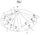
- such a telecommunication system 100 comprises a plurality of user terminals 2, 7 which are ground stations communicating with each other via a satellite 3 with an on-board switch 11 on board.
- the purpose of satellite 3 is to form very long links 6, where the investment in cables proves unrealistic financially or technically.
- the onboard switch 11 then receives on its input ports upstream streams of data or information, that is to say a set of data that go up from the different earth stations 2 to the satellite 3 and distributes, from its output ports. , data downstream flows, ie a set of data that descend from the satellite 3 to other earth stations 7.
- the terminals 2 which transmit to the same input port of the switch 11 are grouped together the same geographic coverage area 1 also known as spot or beam.
- the terminals 7 which receive data from the same output port of the switch 11 are grouped into a coverage area 8.
- the coverage areas are not necessarily disjoint: it is possible in effect that a terminal 7 be covered for example at the same time by several zones blankets.
- the coverage area can carry an information flow whose final destination is common to a plurality of terminals.
- the switch 11 will advantageously point the flow of information to the output port connected to the common coverage area instead of duplicating said information flow to the different coverage areas, thus saving the downstream resources. This can for example be used for multicast information flows, or control information of a collective nature.
- the different user terminals 2 are very often in competition to use the resources that constitute the bandwidth of the uplink and downlink of the satellite 3.
- a solution for uplink management is to use a Demand Assignment Multiple Access (DAMA) controller based on a dynamic resource allocation protocol that allocates to user terminals frequencies and time slots when said terminals express the need. transmitting packet data on uplinks from a terminal to a satellite through requests sent to the DAMA controller. An onboard switch on the satellite then distributes the data packets that arrive on a plurality of uplink links to a plurality of downlinks.
- DAMA Demand Assignment Multiple Access
- a first solution is to make fully compatible for a given period the reasons for access to the upstream links with the reasons for access to the downlinks.
- the switch performs on each of its outputs a deterministic switching and a priori data flows.
- the controller has defined the reasons for this purpose.
- the computation of the compatibility of the access patterns to the upstream and downstream links results from the synthesis of all the requests of the user terminals with the available resources. This calculation is performed by an onboard controller or not, for a defined period during which the patterns are frozen. Any modification of the characteristics of the uplink data flow from a user terminal (for example the bit rate, the destination) generates a new request from said terminal to the switching controller.
- the controller proposes new access patterns to the upstream and downstream links, compatible with the new configuration. This results in a great interdependence between the different user terminals.
- the switching element can be a circuit switch, possibly on the ground.
- a second solution consists in decoupling the access patterns from the upstream links of the downlink access reasons.
- the data is grouped in packets, these packets are provided with a header containing a correlated address with a target user terminal. With this header, packets are auto-routed into the satellite switch.
- a controller manages the access to the upstream links, while the switch, after analyzing the needle address onboard the data and performs on each of its outputs a statistical multiplexing, ..
- the so-called deterministic switching solutions offer high transmission capacity with relative interoperability because the transmission links are transparent (independence of the waveform). But the flow management is not very flexible.
- the so-called statistical switching solutions offer greater flexibility in terms of flow and address management, but their processing capacity is reduced and the dependence on the waveform penalizes interoperability.
- the present invention aims to provide a solution in this sense.
- the invention adjusts the capacity of the pre-analysis processing (demodulation, decoding) to the only category of information to be processed, namely referral requests (fields containing the addresses of the packets, packets necessary for signaling, for example).
- the vast majority of switched information pass "passively", not deserving a regenerative treatment.
- the packet header information remains correlated with the payload data.
- said analysis means comprise control means for configuring the switching means according to the extracted switching information.
- the signal bearing said information is a frequency-multiplexed signal of the AMRF type, first frequency channels being allocated to the useful information while other second frequency channels are allocated to the control information, the means extraction means comprise frequency demultiplexing means followed by filtering means able to provide the information content of the second frequency channels to the control means.
- the signal bearing said information being a time multiplexed signal of the TDMA type
- first groups of time windows are reserved for the useful information whereas other second groups of time windows are dedicated for the information of time.
- the extraction means comprise temporal demultiplexing means capable of providing the information content of the second groups to the control means.
- the system according to the invention comprises means for generating and transmitting a reference clock, the effect of which is to enslave the transmission rate of the packets of control information on board the satellite and useful information and ground control packages.
- the system according to the invention comprises means for delaying any useful data packet in transit in the switching section of the satellite, controllable and activatable by the analysis means.
- the invention also relates to an information transmission device for a terrestrial station of a satellite information transmission system capable of relaying said information from said transmitting terrestrial station to at least one receiving earth station via said satellite, said information consisting of useful information and respectively referral requests, said control information, associated to inform about the useful information, characterized in that said device comprises adaptation means for transporting said information to the satellite, the control information being adapted so that it can be demodulated and decoded separately from the payload data packets on board the satellite.
- the transmission device comprises means for generating bursts of useful information, means for generating referral requests, called control information, each pointing to associated useful information, and frequency and / or time multiplexing means of said information so as to allocate first channels to the useful information and second channels to the control information.
- the first, respectively the second frequency channels are assembled within the same first group, respectively the same second group.
- control information is transmitted in time advance with respect to the useful information to which they are respectively associated, the value of the time advance being reduced by the maximum duration of the analysis and calculation time of the configuration. resulting from all referral requests on board the satellite.
- the useful information and control are issued simultaneously.
- the useful information being transmitted in packets are separated by silent times, called guard times, which are characteristics of the satellite's capacity to switch from a switching configuration to a other.
- the information coming from or going out of the satellite system undergoes conversion of its transport format to ensure compatibility with the satellite system's data transport format.
- the routing requests generated ensure the propagation of the notion of quality of service through the satellite system, when said notion of quality of service exists outside the satellite system.
- the generated routing requests ensure the correct routing of useful information so that, from the point of view outside the satellite system, the useful information has actually been directed to the destinations described by the address information. included in the referral request and associated with the useful data before entering the satellite system, thus implementing a correspondence between the satellite output ports and the address information associated with the useful information before entering the system satellite.
- the transmission rates of the useful information and controls are slaved to the rate of the reference clock located on board the satellite, this reference clock being conveyed in a downlink control channel.
- the transmission method according to 11nvention masters the characteristics of useful information flow in terms of useful throughput by an indication of resource management of the upstream and downstream links conveyed on a downlink control channel.
- the transmission method according to the invention controls the characteristics of the transmission characteristics of the modulated signal in terms of bit rate, phase, power by an indication of demodulation and decoding carried on a transmission channel. downward control.
- the transmission method according to the invention controls the centering of the useful information packets by separating each of the useful deformation packets from a guard period common to the entire satellite system, these guard periods occurring at the same time. satellite at the same time, in order to operate the switching configuration change without service interruption, this synchronization using the centering information from a downlink control channel.
- the resolution of the conflict situations that may occur on the same output port uses a temporal re-allocation, a frequency re-allocation or a port re-allocation.
- the referral request associated with the redirected useful information packet contains a high priority recommendation.
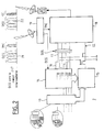
- the figure 2 is a first embodiment in the form of functional blocks of a node of type "edge" on the ground.
- edge node relates to an access point of the network collecting and / or broadcasting information from one and / or to a subscriber access node and respectively broadcasting and / or collecting information to and / or one or more central nodes or "core" centralizing the information.
- the terminals 2 and 7 are "edge" nodes and the satellite 3 is a core node, the subscriber accesses in the extension of the continuous lines connected to the terminals 2.7 not being represented.
- the edge nodes will be called intermediate nodes. It will be seen below that a master-slave relationship exists between the satellite and the stations, the satellite providing inter alia the packet synchronization clock at stations 2, 7.
- each port represents the set of information flows transmitted by an edge node, here a terminal 2 which will be called in the following a terrestrial station.
- the header of a burst of data is first transmitted on the CC channel ("Control Channel” in English), followed, after the predetermined duration, of the burst of data associated with it on a parallel channel DC (" Data Channel ").
- the data header must contain all the information necessary for the referral by the controller on board the satellite.
- Each packet header is transmitted as a packet of fixed length and named burst header packet or BHP ("Burst Header Packet"). It is required that the BHP is transmitted before the corresponding burst with an offset of length ⁇ predetermined. This time interval allows the resolution of the switching request within the controller. The parameters that influence the offset will be specified later.
- BHP Burst Header Packet
- the control and data channels are connected to a satellite adapter 18 which performs mainly packet synchronization functions of packet centering, modulation, coding and frequency multiplexing.
- data bursts are transmitted on an interval-synchronized path ("slot-synchronized path").
- the bursts are cut into packets of fixed size ("slot” in English), and are separated by so-called guard time intervals.
- the synchronization information, or centering packets in the associated time slot is contained in a channel called in the TMC suite (for "TeleMetric Channel” in English), transmitted by the satellite, as described below, and received at station 2 by a receiver 19.
- This centering information allows the satellite transmission system to be fully synchronous, the beginning of the useful data packets on the uplink links all occurring at the same time.
- a period of silence between the payload packets allows the satellite to switch from one switching plan to another. This period of silence known as the on-call time is respected by all the transmitting stations towards the satellite. All uplinks present this period of silence at the same time.
- the satellite is provided with means for passing from one switch configuration to another of the switch for a duration compatible with the guard period existing between each payload packet.
- the size of the payload packets is fixed, common to all stations. However, it is conceivable that the size of the payload packets is variable, and that for each payload packet the switching request informs the switching controller of the transit time of the associated payload packet on board. satellite.
- the TMC channel may also carry several other information useful for the efficient operation of the system: thus, this TMC channel may carry an indicator for estimating the characteristics of the demodulation and decoding of control data on board the satellite, an indicator of estimation of the downlink load rates by the switching control body, or an estimation indicator describing the state of onboard bodies on board the satellite. These indicators are generated, following an estimation, by an estimator 290 of the figure 5 described below.
- the upper part of the figure 2 illustrates respectively the spectrum 21 of the signal received by the station 2, comprising the group of DCG Data Channels and the TMC channel, and the spectrum 22 of the transmitted signal corresponding to the multiplex signal of the group of DCG Data Channels with the CC channel.
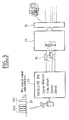
- the figure 3 represents an embodiment of a receiving station 20.
- the signal emitted by the satellite is received by the receiving station, which carries out in a satellite receiver block 23, the signal detection operations, in particular thanks to the frequency demultiplexing signal TMC, demodulation and decoding. These operations, known per se, will not be detailed in the present application.
- the packets are reconstituted into bursts 24, which are transmitted to a network packet generator 25 (of the IP type).
- the different bursts 24 allow the return of IP packets, this through means known per se. These means may be for example an indicator contained in each slave identifying the destination IP packet or packets contained in the burst, or a network controller, not shown, assigning each slave its destination by appropriate means.
- a network adapter 26 allows the configuration of the resulting packets according to the network protocols.
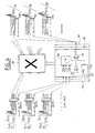
- the figure 4 represents an embodiment of a switching system 27 according to the invention. This system 27 is integrated with the satellite.
- Ports ⁇ port1, port2, port3 ⁇ representing, as mentioned above, all information flows transmitted by respective edge nodes 2, are received at corresponding inputs of the satellite.
- Each port has a DCG Data Channel Group and a CCG Control Channel Group.
- the payload channels of each port are received by respective inputs of a switch 28, while the control data channels (including the BHPs) of the same ports are directed to corresponding inputs of a controller 29.
- the BHPs After demodulation and decoding, the BHPs will then be analyzed by a scheduling block for allocating useful data bursts. pointed by the BHP to the satellite output ports, this assignment being made according to parameters indicated in the BHP, such as the duration and the destination of the payload bursts, their QoS, their priority, etc.
- This block 30 then controls the switching of useful data bursts transiting "transparently" (ie without undergoing demodulation / decoding operations) in the switch 28, so as to be found respectively on the adapted output ports.
- a clock generator 31 generates the centering information TMC which is multiplexed by the information multiplexer 32 with the other information coming from the block 30.
- the switching plans of the switch 28 and the downstream ports 33 are clocked at a time. common clock rhythm.
- the figure 5 shows in detail the switch 28 and its interconnections with the controller 29.
- the flow of information from the n transmitting stations representing the different ports ⁇ port1; port2; ..; portn ⁇ is shown schematically by means of an arrow 35.
- This multiplex stream is then demultiplexed and converted to lower frequencies compatible with subsequent equipment in the processing chain.
- N groups of channels each having p + 1 channels are then respectively faced with blocks 36 of channel switching.
- each block 36 is composed of p + 1 switching sub-matrices, each dedicated to an input channel and an output channel of the corresponding block 36.
- Each channel switching block has p inputs for receiving the associated channel group and p outputs.
- the DC control channel of the group is isolated and directed to an input of a block 37 called MCDDD (for "MultiCarrier Demultiplexer Demodulator Decoder" in English).
- MCDDD MultiCarrier Demultiplexer Demodulator Decoder
- This block 37 receiving the n control channels of n groups of channels has the function of demultiplexing, demodulation (by a block 371 demodulation) and decoding (by a block 372 of decoding) of these channels.
- This block also has the role of establishing an estimate for centering the intervals of control information with respect to the master clock of the controller.
- the analysis of the different requests for switching the control information gives rise to instructions for controlling the controller, on the one hand Scom1 to the p sub-matrices of the n blocks 36 for switching channels and on the other hand Scom2 to p port switching sub-matrix of a port switching matrix 38 n * n.
- the matrix directs the different useful data channels to the ports or spots adapted according to their destination and the availability of the ports.
- the controller also provides the centering signals (TMC) in a block 39 for modulation / coding.
- TMC centering signals
- the n outputs of this block 39 provide the centering information for the n TMC channels included in the n groups of channels at the output of the matrix 38.
- this centering information is provided in the form of TMP packets ("TeleMetry Packet").
- TMP packets TMP packets
- the n groups at the output of the matrix 38 then undergo a first operation of multiplexing and conversion to higher frequencies respectively by a block 40 of multiplexing / conversion.
- the signals leaving each of the n blocks 40 are then multiplexed and then converted into higher frequencies adapted for radio transmission by a block 41.
- the delays mentioned above for the analysis of the routing requests can be arranged either at each sub-matrix of the channel switching blocks 36 or at the sub-matrix level of the port switching matrix 38.
- controller may also include means for destroying any non-point-input useful data packet at the input of the switch, these destruction means being controlled and activated by the controller.
- Network packets typically IP packets
- the size of these packets is variable, and often uncontrolled.
- a first step is therefore to build data bursts from the aggregation of these network packets.
- the aggregation criteria are-among others- the same destination, the same level of quality of service, ...
- the size of these bursts can be fixed or variable, the time of constitution of the salvo can also be a criterion of determination . For example, in the case of a quality of service of the VoIP type (commonly called VoIP), the delay allowed on the network packets is very small.
- the arrival time of the network packets determines the bursts closing time and therefore their size.
- the minimum size of the bursts is fixed by the carrying capacity of the transport packets (described below) and the maximum size is often determined by the maximum size of a network packet.
- the assembly scheme of the burst network packets is described in a burst preamble, indicating the number and the size of the network packets assembled in the burst, this preamble thus allowing the reconstruction of the network packets in the organ 25.
- a burst segmentation step can be introduced.
- the bursts are cut into fixed size packets (the segments).
- a segment preamble is attached to it, containing among other things an indicator identifying the burst in the system to which the segment is attached, as well as the rank of the segment in the burst.
- the segment and segment preamble assembly is then subjected to protection against transmission errors (coding). Once coded, this set segment and preamble, is eventually supplemented by information of the type 'single word' sometimes required by the demodulation algorithms implemented in satellite receiver block 23. From the point of view of the physical layer, the useful data packets that will be switched by the switch 28 correspond to these coded fixed size packets, accompanied by their unique word.
- control information switching requests
- the transmission of this frequency channel of control information is in advance time relative to the useful information, thereby saving memory space on board the satellite. It is obvious that the essence of the invention consists in the possibility of dissociating this control information useful information to make them undergo different treatment. Consequently, the invention also covers the case, not described, of control and useful information transmitted according to a mode of the TDMA or even CDMA type, the control information being transmitted in time advance of the associated useful information, on the same channel frequency or different.
Claims (24)
- Informationsschaltungssystem für einen Satelliten (3) in einem Satelliten-Informationsübertragungssystem (2, 3, 7), das die Informationen von einer ersten terrestrischen Sendezone über den Satelliten zu einer zweiten terrestrischen Empfangszone senden kann, wobei sich die Informationen aus Nutzinformationen (DCG) bzw. assoziierten Routing-Informationen (CCG), Steuerinformationen genannt, zum Informieren über die Verkehrslenkung von Nutzinformationen zusammensetzen, wobei das System Folgendes umfasst:- Mittel (29, 37, 39) zum Analysieren von Informationen von einem die Steuerinformationen tragenden Signal, wobei die Analysemittel Mittel zum Extrahieren (37) von Steuerinformationen umfassen, wobei die Extraktionsmittel (37) Mittel zum Demodulieren (371) und zum Decodieren (372) der Steuerinformationen umfassen,- Mittel (28) zum Schalten der Nutzinformationen in Abhängigkeit vom Ergebnis der Analyse der assoziierten Routing-Anforderungen zu wenigstens einem Port unter mehreren Sendeports zum Senden zu der Empfangszone,dadurch gekennzeichnet, dass die Informationsanalysemittel nur die Steuerinformationen empfangen, so dass eine Demodulations- und Decodieroperation nur an den Steuerinformationen vorgenommen wird, wobei die Nutzinformationen keine Demodulations- oder Decodieroperation erfahren.
- Schaltungssystem nach Anspruch 1, dadurch gekennzeichnet, dass die Analysemittel Befehlsmittel (30) zum Konfigurieren der Schaltmittel (28) in Abhängigkeit von den extrahierten Routing-Informationen umfassen.
- Schaltungssystem nach Anspruch 2, dadurch gekennzeichnet, dass das die Informationen führende Signal ein frequenzmultipliziertes Signal des FDMA-Typs ist, wobei die ersten Frequenzkanäle den Nutzinformationen zugeordnet werden, während andere zweite Frequenzkanäle den Steuerinformationen zugeordnet werden, wobei andere Extraktionsmittel Mittel zum Frequenzdemultiplexieren gefolgt von Filtermitteln umfassen, die den Informationsinhalt der zweiten Frequenzkanäle den Befehlsmitteln zuführen können.
- Schaltungssystem nach Anspruch 2, dadurch gekennzeichnet, dass das die Informationen tragende Signal ein zeitmultiplexiertes Signal des TDMA-Typs ist, wobei die ersten Zeitfenstergruppen für die Nutzinformationen reserviert sind, während andere zweite Zeitfenstergruppen für die Steuerinformationen dediziert sind, wobei die Extraktionsmittel Zeitdemultiplexiermittel umfassen, die den Informationsinhalt der zweiten Gruppen den Befehlsmitteln zuführen können.
- Schaltungssystem nach einem der vorherigen Ansprüche, dadurch gekennzeichnet, dass es Erzeugungsmittel (31) und Übertragungsmittel (39) eines Referenzzeitgebers umfasst, um den Sendetakt von Steuerinformationspaketen an Bord des Satelliten und den von Nutzinformationspaketen und Steuerinformationspaketen am Boden zu regeln.
- Schaltungssystem nach einem der vorherigen Ansprüche, dadurch gekennzeichnet, dass es Schätzmittel (290) umfasst, um Folgendes zu schätzen:- die Qualität der Synchronisation, Zentrieren von Steuerinformationspaketen genannt, wobei die Zentrierungsinformation dann zu einer terrestrischen Station übertragen werden kann, um die von dieser Station zu sendenden Nutz- und Steuerinformationspakete zu zentrieren,- und/oder die Demodulations- und Decodierungscharakteristiken von Steuerinformationen an Bord des Satelliten,- und/oder die Belastungen von Downlinks,- und/oder die Zustände von Geräten an Bord des Satelliten.
- Schaltungssystem nach einem der vorherigen Ansprüche, dadurch gekennzeichnet, dass es Mittel zum Verzögern jedes Nutzdatenpakets im Transit im Schaltungsteil des Satelliten umfasst, die von den Analysemitteln gesteuert und aktiviert werden können.
- Vorrichtung zum Übertragen von Informationen für eine terrestrische Station eines Satelliten-Informationsübertragungssystems, das die Informationen der terrestrischen Sendestation über den Satelliten zu wenigstens einer terrestrischen Empfangsstation weiterleiten kann, wobei sich die Informationen aus Nutzinformationen und jeweils assoziierten Routing-Informationen, Steuerinformationen genannt, zusammensetzen, die zum Informieren über die Nutzinformationen bestimmt sind,
dadurch gekennzeichnet, dass die Vorrichtung Adaptionsmittel für den Transport der Informationen zum Satelliten umfasst, wobei die Steuerinformationen so ausgelegt sind, dass sie separat von den Nutzdatenpaketen an Bord des Satelliten demoduliert und decodiert werden können. - Übertragungsvorrichtung nach Anspruch 8, dadurch gekennzeichnet, dass sie Mittel zum Erzeugen (14) von Nutzinformationsbündeln, Mittel (15) zum Erzeugen von Routing-Anforderungen, Steuerinformationen genannt, die jeweils auf die assoziierten Nutzinformationen zeigen, und Mittel (18) zum Frequenz- und/oder Zeitmultiplexieren der Informationen umfasst, um erste Kanäle (DC) den Nutzinformationen und zweite Kanäle (CC) den Steuerinformationen zuzuordnen.
- Übertragungsvorrichtung nach Anspruch 8 oder 9, dadurch gekennzeichnet, dass die ersten bzw. die zweiten Frequenzkanäle innerhalb einer selben ersten Gruppe (DCG) bzw. einer selben zweiten Gruppe (CCG) vereinigt werden.
- Verfahren zum Übertragen von Informationen in einem Satelliten-Informationsübertragungssystem, das die Informationen in einer ersten terrestrischen Sendezone über den Satelliten zu einer zweiten terrestrischen Empfangszone weiterleiten kann, wobei sich die Informationen aus Nutzinformationen und jeweils assoziierten Routing-Anforderungen, Steuerinformationen genannt, zusammensetzen, um über die in dem Satelliten durchzuführende Leitwegführung von Nutzinformationen zu informieren, wobei das Verfahren Folgendes beinhaltet:- einen Schritt des Übertragens von Nutzinformationen auf ersten Kanälen,- einen Schritt des Übertragens von Steuerinformationen auf zweiten Kanälen, so dass nur die Steuerinformationen an Bord des Satelliten demoduliert und decodiert werden können.
- Übertragungsverfahren nach Anspruch 11, dadurch gekennzeichnet, dass die Steuerinformationen zeitlich vor den Nutzinformationen gesendet werden, mit denen sie jeweils assoziiert sind, wobei der Wert des zeitlichen Vorsprungs um die maximale Dauer der Analyse- und Berechnungszeit der Routing-Konfiguration reduziert wird, die aus allen Routing-Anforderungen an Bord des Satelliten resultiert.
- Übertragungsverfahren nach Anspruch 11, dadurch gekennzeichnet, dass die Nutz- und Steuerinformationen gleichzeitig gesendet werden.
- Übertragungsverfahren nach einem der Ansprüche 11 bis 13, dadurch gekennzeichnet, dass, da die Nutzinformationen paketweise gesendet werden, die Nutzinformationspakete in Ruhezeiten getrennt werden, Schutzzeiten genannt, die für die Kapazität des Satelliten, von einer Routing-Konfiguration zu einer anderen überzugehen, charakteristisch sind.
- Übertragungsverfahren nach einem der Ansprüche 11 bis 14, dadurch gekennzeichnet, dass die Informationen, die das Satellitensystem verlassen oder auf ihrem Weg aus ihm sind, eine Umwandlung ihres Transportformats erfahren, um ihre Kompatibilität mit dem Transportformat der für das Satellitensystem spezifischen Daten zu gewährleisten.
- Übertragungsverfahren nach einem der Ansprüche 11 bis 15, dadurch gekennzeichnet, dass die erzeugten Routing-Anforderungen die Ausbreitung der Quality of Service über das Satellitensystem gewährleisten, wenn die Quality of Service außerhalb des Satellitensystems existiert.
- Übertragungsverfahren nach einem der Ansprüche 11 bis 16, dadurch gekennzeichnet, dass die erzeugten Routing-Anforderungen eine korrekte Verkehrslenkung der Nutzinformationen gewährleisten, damit mit Blick von außerhalb des Satellitensystems die Nutzinformationen effektiv zu den in den Adressinformationen beschriebenen Zielen geleitet werden, die in der Routing-Anforderung enthalten und mit den Nutzdaten assoziiert sind, bevor sie in das Satellitensystem eintreten, wodurch eine Korrespondenz zwischen den Ausgangsports des Satelliten und der mit den Nutzdaten assoziierten Adressinformation vor dem Eintreten in das Satellitensystem hergestellt wird.
- Übertragungsverfahren nach einem der Ansprüche 11 bis 17, dadurch gekennzeichnet, dass die Senderate der Nutz- und Steuerinformationen auf den an Bord des Satelliten befindlichen Referenztaktgeber geregelt wird, wobei dieser Referenztaktgeber in einem Steuerkanal der Downlink geführt wird.
- Übertragungsverfahren nach einem der Ansprüche 11 bis 18, dadurch gekennzeichnet, dass es die Charakteristiken des Nutzinformationsflusses im Sinne des nützlichen Durchsatzes durch eine Managementanzeige von Ressourcen auf der Uplink und der Downlink regelt, die auf einem Downlink-Steuerkanal geführt werden.
- Übertragungsverfahren nach einem der Ansprüche 11 bis 19, dadurch gekennzeichnet, dass es die Charakteristiken des Sendens des modulierten Signals im Sinne des Bit-, Phasen-, Leistungsrhythmus durch Anzeigen von Demodulation und Decodierung verwaltet, die auf einem Downlink-Steuerkanal geführt werden.
- Übertragungsverfahren nach einem der Ansprüche 11 bis 20, dadurch gekennzeichnet, dass es die Zentrierung von Nutzinformationspaketen durch Trennen der einzelnen Nutzinformationspakete durch eine dem gesamten Satellitensystem gemeinsame Schutzperiode verwaltet, wobei diese Schutzperioden im selben Augenblick im Satelliten auftreten, um eine Änderung der Schaltungskonfiguration ohne Diensteunterbrechung zu bewirken, wobei diese Synchronisierung die von einem Steuerkanal der Downlink ausgegebenen Zentrierungsinformationen nutzt.
- Verfahren zum Schalten von Informationen für einen Satelliten in einem Satelliten-Informationsübertragungssystem, das die Informationen einer ersten terrestrischen Sendezone über den Satelliten zu einer zweiten terrestrischen Empfangszone weiterleiten kann, wobei sich die Informationen aus Nutzinformationen und jeweils assoziierten Routing-Anforderungen, Steuerinformationen genannt, zusammensetzt, die zum Informieren über die an den Nutzinformationen durchzuführende Verkehrslenkung bestimmt sind, wobei das Verfahren Folgendes beinhaltet:- einen Informationsanalyseschritt,- einen Schritt zum Schalten der Nutzinformationen in Abhängigkeit von den assoziierten und analysierten Routing-Anforderungen zu verschiedenen Sendeports zur Empfangszone,dadurch gekennzeichnet, dass der Analyseschritt darin besteht, eine Demodulations- und Decodieroperation nur an den Steuerinformationen durchzuführen, wobei die Nutzinformationen keine Demodulations- oder Decodieroperation erfahren.
- Schaltungsverfahren nach Anspruch 22, dadurch gekennzeichnet, dass die Auflösung von Konfliktsituationen, die am selben Ausgangsport auftreten können, eine zeitliche Neuzuordnung, eine Frequenzneuzuordnung oder eine Portneuzuordnung beinhaltet.
- Schaltungsverfahren nach Anspruch 22 oder 23, dadurch gekennzeichnet, dass im Falle einer Neuzuordnung die mit dem Paket von umgeleiteten Nutzinformationen assoziierte Routing-Anforderung eine Hochprioritätsempfehlung enthält.
Applications Claiming Priority (2)
| Application Number | Priority Date | Filing Date | Title |
|---|---|---|---|
| FR0202770A FR2837043B1 (fr) | 2002-03-05 | 2002-03-05 | Systeme de commutation, dispositif de transmission, procede de transmission et procede de commutation pour satellite |
| FR0202770 | 2002-03-05 |
Publications (2)
| Publication Number | Publication Date |
|---|---|
| EP1343258A1 EP1343258A1 (de) | 2003-09-10 |
| EP1343258B1 true EP1343258B1 (de) | 2012-11-14 |
Family
ID=27741441
Family Applications (1)
| Application Number | Title | Priority Date | Filing Date |
|---|---|---|---|
| EP03290353A Expired - Lifetime EP1343258B1 (de) | 2002-03-05 | 2003-02-14 | Satellitenschaltungsystem |
Country Status (4)
| Country | Link |
|---|---|
| US (1) | US7701894B2 (de) |
| EP (1) | EP1343258B1 (de) |
| JP (1) | JP4592254B2 (de) |
| FR (1) | FR2837043B1 (de) |
Cited By (1)
| Publication number | Priority date | Publication date | Assignee | Title |
|---|---|---|---|---|
| CN103067326A (zh) * | 2012-12-10 | 2013-04-24 | 上海航天测控通信研究所 | 一种遥测与数传一体化发射机 |
Families Citing this family (9)
| Publication number | Priority date | Publication date | Assignee | Title |
|---|---|---|---|---|
| KR100678223B1 (ko) * | 2003-03-13 | 2007-02-01 | 삼성전자주식회사 | 통신시스템의 패킷 전송 장치 및 방법 |
| US7725759B2 (en) * | 2005-06-29 | 2010-05-25 | Sigmatel, Inc. | System and method of managing clock speed in an electronic device |
| US8078225B2 (en) * | 2007-07-02 | 2011-12-13 | Infineon Technologies Ag | Communication device, mobile device and method of communication |
| US8208484B2 (en) * | 2010-01-11 | 2012-06-26 | Telefonaktiebolaget L M Ericsson (Publ) | Forwarding a packet within a router using fragments over an interconnect |
| CN101997596A (zh) * | 2010-12-03 | 2011-03-30 | 北京中交通信科技有限公司 | 一种基于卫星的应急通信方法、装置及系统 |
| JP5723205B2 (ja) * | 2011-04-28 | 2015-05-27 | 株式会社東芝 | 衛星通信用変復調装置、データ伝送アダプタ、及び変復調部 |
| EP3127254B1 (de) * | 2014-03-31 | 2019-06-12 | Hughes Network Systems, LLC | System und verfahren zur überlastungsverwaltung für downlink-warteschlangen digitaler verarbeitungssatelliten für differenzierte dienstqualität (qos) |
| FR3026257B1 (fr) * | 2014-09-22 | 2016-12-09 | Thales Sa | Procede et gestion dynamique de ressources et systeme associe |
| CN105429691B (zh) * | 2015-10-30 | 2019-01-25 | 航天东方红卫星有限公司 | 一种数传地面测试系统实时分级数据判读方法 |
Citations (1)
| Publication number | Priority date | Publication date | Assignee | Title |
|---|---|---|---|---|
| EP1158701A2 (de) * | 2000-05-22 | 2001-11-28 | TRW Inc. | Vorrichtung zur Steuerung der Leitweglenkung in einem Satellitenkommunikationssystem |
Family Cites Families (16)
| Publication number | Priority date | Publication date | Assignee | Title |
|---|---|---|---|---|
| IT1278517B1 (it) * | 1994-07-25 | 1997-11-24 | Motorola Inc | Procedimento per il trasferimento intersatellitare di pacchetti di dati. |
| US5951709A (en) * | 1995-02-28 | 1999-09-14 | Kabushiki Kaisha Toshiba | Radio communication system using TDD scheme |
| US5640386A (en) * | 1995-06-06 | 1997-06-17 | Globalstar L.P. | Two-system protocol conversion transceiver repeater |
| US5790939A (en) * | 1995-06-29 | 1998-08-04 | Hughes Electronics Corporation | Method and system of frame timing synchronization in TDMA based mobile satellite communication system |
| US5959999A (en) * | 1996-09-20 | 1999-09-28 | Linkabit Wireless, Inc. | Providing control-function data in communication-data channel of a full-mesh satellite communication network by dynamic time-slot assignment in TDMA-frame communication channel |
| US5898680A (en) * | 1996-11-05 | 1999-04-27 | Worldspace, Inc. | System for providing location-specific data to a user |
| US6108319A (en) * | 1996-11-05 | 2000-08-22 | Worldspace International Networks, Inc. | Satellite payload processing system providing on-board rate alignment |
| FR2761557B1 (fr) * | 1997-03-28 | 1999-04-30 | Alsthom Cge Alcatel | Procede de transmission sur une pluralite de supports de transmission, a repartition dynamique des donnees, et emetteur et terminal correspondants |
| JP3204303B2 (ja) * | 1997-11-28 | 2001-09-04 | 日本電気株式会社 | 無線atm通信方式 |
| US6426959B1 (en) * | 1998-01-20 | 2002-07-30 | Innovative Communications Technologies, Inc. | System and method for facilitating component management in a multiple vendor satellite communications network |
| US6366761B1 (en) * | 1998-10-06 | 2002-04-02 | Teledesic Llc | Priority-based bandwidth allocation and bandwidth-on-demand in a low-earth-orbit satellite data communication network |
| US6400925B1 (en) * | 1999-02-25 | 2002-06-04 | Trw Inc. | Packet switch control with layered software |
| US6597669B1 (en) * | 1999-03-16 | 2003-07-22 | Northrop Grumman Corporation | Queue segmentation and addressing method and apparatus for a cell switch in a processing communications satellite |
| US6738350B1 (en) * | 2000-03-16 | 2004-05-18 | Hughes Electronics Corporation | Congestion avoidance approach for a switching communication system with transmission constraints |
| US7031653B1 (en) * | 2000-03-29 | 2006-04-18 | Hughes Electronics Corporation | Switch matrix for satellite payloads with multiple uplink beams and on-board signal processing |
| US6904265B1 (en) * | 2001-04-11 | 2005-06-07 | Hughes Electronics Corporation | Capacity management in a broadband satellite communications system |
-
2002
- 2002-03-05 FR FR0202770A patent/FR2837043B1/fr not_active Expired - Fee Related
-
2003
- 2003-02-14 EP EP03290353A patent/EP1343258B1/de not_active Expired - Lifetime
- 2003-02-25 JP JP2003047631A patent/JP4592254B2/ja not_active Expired - Lifetime
- 2003-02-28 US US10/375,142 patent/US7701894B2/en active Active
Patent Citations (1)
| Publication number | Priority date | Publication date | Assignee | Title |
|---|---|---|---|---|
| EP1158701A2 (de) * | 2000-05-22 | 2001-11-28 | TRW Inc. | Vorrichtung zur Steuerung der Leitweglenkung in einem Satellitenkommunikationssystem |
Cited By (2)
| Publication number | Priority date | Publication date | Assignee | Title |
|---|---|---|---|---|
| CN103067326A (zh) * | 2012-12-10 | 2013-04-24 | 上海航天测控通信研究所 | 一种遥测与数传一体化发射机 |
| CN103067326B (zh) * | 2012-12-10 | 2015-10-14 | 上海航天测控通信研究所 | 一种遥测与数传一体化发射机 |
Also Published As
| Publication number | Publication date |
|---|---|
| JP4592254B2 (ja) | 2010-12-01 |
| US7701894B2 (en) | 2010-04-20 |
| FR2837043B1 (fr) | 2004-06-04 |
| FR2837043A1 (fr) | 2003-09-12 |
| US20030169699A1 (en) | 2003-09-11 |
| EP1343258A1 (de) | 2003-09-10 |
| JP2003298489A (ja) | 2003-10-17 |
Similar Documents
| Publication | Publication Date | Title |
|---|---|---|
| EP1343259B1 (de) | Mittelverwaltungsvorrichtung für ein Satelliten-Telekommunikationssystem | |
| EP0204191B1 (de) | Verfahren und Anordnung zur Satellitenübertragung mit TDMA | |
| EP0601653B1 (de) | System zur Übertragung von Information mit unterschiedlichen Bitraten und Sendestation für ein solches System | |
| EP2725721B1 (de) | Dynamische Zuordnung von aufgeteilten Ressourcen in einem Zeit-Frequenz-Plan, und entsprechende Vorrichtung | |
| EP1343258B1 (de) | Satellitenschaltungsystem | |
| FR2787658A1 (fr) | Procede de gestion de modes de communication pour un aeronef | |
| EP2005770A1 (de) | Verfahren zum optimieren der zuteilung von betriebsmitteln in einem zellularen netzwerk mit einer gemeinsam benutzten funkübertragungsstrecke, netzwerk und netzwerkadapter dafür | |
| FR2718314A1 (fr) | Procédé et système d'acheminement de paquets de données suivant des directions pouvant être adaptées en fonction d'une meilleure répartition de l'utilisation des ressources d'un réseau de télécommunications. | |
| EP3416302B1 (de) | Telekommunikationssystem, das einen eingebauten cache-server in einer plattform in grosser höhe umfasst, und entsprechendes datenübertragungsverfahren | |
| EP3494653B1 (de) | Satellitentelekommunikationssystem mit einer optischen gateway-verbindung und einer funk-gateway-verbindung und steuerungsverfahren | |
| CA2256556A1 (fr) | Procede de transmission sur une pluralite de supports de transmission, a repartition dynamique des donnees, et emetteur et terminal correspondants | |
| EP1545140B1 (de) | Schicht-ZweiI Kompression/Dekompression in einem zellularen Kommunikationsnetz | |
| US20200358704A1 (en) | Packet forwarding system and method | |
| CA2525276C (fr) | Gestion de ressources d'un reseau de communications de type point a multipoint ou multipoint a multipoint, par deux niveaux d'allocation | |
| EP3203656B1 (de) | Verfahren zur transparenten ende-zu-ende übermittlung von datenpaketen in einem regenerativen satellitennetz mit inter-satelliten verbindungen | |
| EP1009109B1 (de) | Telekommunikationssystem und Mehrstrahlsatellit dafür | |
| EP0831601B1 (de) | Vorrichtung zum Übertragen digitaler Informationen über Satellit von mehreren Bodenstationen | |
| FR2895852A1 (fr) | Reservation implicite de ressources dans un reseau de communication de type point a multipoint ou multipoint a multipoint | |
| EP1224833B1 (de) | Robuster transport von ip verkehr über wdm mittels optischer burstvermittlung | |
| US20020054576A1 (en) | Distributed asynchronous transfer mode (ATM) switch architecture for satellites | |
| EP0956682B1 (de) | Vorrichtung zur allgemeinen leitweglenkung von nachrichten in verschiedenen formaten und unterschiendlichen protokollen | |
| BE1026657B1 (nl) | Satellietcommunicatiesysteem | |
| FR2847748A1 (fr) | Procede et dispositif de routage pour un systeme multiplex numerique | |
| FR2806577A1 (fr) | Systeme de telecommunication dans lequel chaque terminal comporte plusieurs connexions | |
| EP1968258A1 (de) | Hilfsvorrichtung für das Querrouting von Verkehr zwischen zwei weit entfernten Standorten innerhalb eines Funkkommunikationsnetzes |
Legal Events
| Date | Code | Title | Description |
|---|---|---|---|
| PUAI | Public reference made under article 153(3) epc to a published international application that has entered the european phase |
Free format text: ORIGINAL CODE: 0009012 |
|
| AK | Designated contracting states |
Kind code of ref document: A1 Designated state(s): AT BE BG CH CY CZ DE DK EE ES FI FR GB GR HU IE IT LI LU MC NL PT SE SI SK TR |
|
| AX | Request for extension of the european patent |
Extension state: AL LT LV MK RO |
|
| 17P | Request for examination filed |
Effective date: 20040310 |
|
| AKX | Designation fees paid |
Designated state(s): AT BE BG CH CY CZ DE DK EE ES FI FR GB GR HU IE IT LI LU MC NL PT SE SI SK TR |
|
| RAP1 | Party data changed (applicant data changed or rights of an application transferred) |
Owner name: ALCATEL LUCENT |
|
| 17Q | First examination report despatched |
Effective date: 20071114 |
|
| RAP1 | Party data changed (applicant data changed or rights of an application transferred) |
Owner name: ALCATEL LUCENT |
|
| GRAP | Despatch of communication of intention to grant a patent |
Free format text: ORIGINAL CODE: EPIDOSNIGR1 |
|
| GRAS | Grant fee paid |
Free format text: ORIGINAL CODE: EPIDOSNIGR3 |
|
| GRAA | (expected) grant |
Free format text: ORIGINAL CODE: 0009210 |
|
| AK | Designated contracting states |
Kind code of ref document: B1 Designated state(s): AT BE BG CH CY CZ DE DK EE ES FI FR GB GR HU IE IT LI LU MC NL PT SE SI SK TR |
|
| RAP1 | Party data changed (applicant data changed or rights of an application transferred) |
Owner name: THALES |
|
| REG | Reference to a national code |
Ref country code: GB Ref legal event code: FG4D Free format text: NOT ENGLISH |
|
| REG | Reference to a national code |
Ref country code: CH Ref legal event code: EP Ref country code: AT Ref legal event code: REF Ref document number: 584434 Country of ref document: AT Kind code of ref document: T Effective date: 20121115 |
|
| REG | Reference to a national code |
Ref country code: IE Ref legal event code: FG4D Free format text: LANGUAGE OF EP DOCUMENT: FRENCH |
|
| REG | Reference to a national code |
Ref country code: DE Ref legal event code: R096 Ref document number: 60342571 Country of ref document: DE Effective date: 20130110 |
|
| REG | Reference to a national code |
Ref country code: NL Ref legal event code: VDEP Effective date: 20121114 |
|
| REG | Reference to a national code |
Ref country code: AT Ref legal event code: MK05 Ref document number: 584434 Country of ref document: AT Kind code of ref document: T Effective date: 20121114 |
|
| PG25 | Lapsed in a contracting state [announced via postgrant information from national office to epo] |
Ref country code: FI Free format text: LAPSE BECAUSE OF FAILURE TO SUBMIT A TRANSLATION OF THE DESCRIPTION OR TO PAY THE FEE WITHIN THE PRESCRIBED TIME-LIMIT Effective date: 20121114 Ref country code: SE Free format text: LAPSE BECAUSE OF FAILURE TO SUBMIT A TRANSLATION OF THE DESCRIPTION OR TO PAY THE FEE WITHIN THE PRESCRIBED TIME-LIMIT Effective date: 20121114 Ref country code: ES Free format text: LAPSE BECAUSE OF FAILURE TO SUBMIT A TRANSLATION OF THE DESCRIPTION OR TO PAY THE FEE WITHIN THE PRESCRIBED TIME-LIMIT Effective date: 20130225 |
|
| PG25 | Lapsed in a contracting state [announced via postgrant information from national office to epo] |
Ref country code: PT Free format text: LAPSE BECAUSE OF FAILURE TO SUBMIT A TRANSLATION OF THE DESCRIPTION OR TO PAY THE FEE WITHIN THE PRESCRIBED TIME-LIMIT Effective date: 20130314 Ref country code: CY Free format text: LAPSE BECAUSE OF FAILURE TO SUBMIT A TRANSLATION OF THE DESCRIPTION OR TO PAY THE FEE WITHIN THE PRESCRIBED TIME-LIMIT Effective date: 20121114 Ref country code: GR Free format text: LAPSE BECAUSE OF FAILURE TO SUBMIT A TRANSLATION OF THE DESCRIPTION OR TO PAY THE FEE WITHIN THE PRESCRIBED TIME-LIMIT Effective date: 20130215 Ref country code: SI Free format text: LAPSE BECAUSE OF FAILURE TO SUBMIT A TRANSLATION OF THE DESCRIPTION OR TO PAY THE FEE WITHIN THE PRESCRIBED TIME-LIMIT Effective date: 20121114 |
|
| PG25 | Lapsed in a contracting state [announced via postgrant information from national office to epo] |
Ref country code: AT Free format text: LAPSE BECAUSE OF FAILURE TO SUBMIT A TRANSLATION OF THE DESCRIPTION OR TO PAY THE FEE WITHIN THE PRESCRIBED TIME-LIMIT Effective date: 20121114 |
|
| PG25 | Lapsed in a contracting state [announced via postgrant information from national office to epo] |
Ref country code: CZ Free format text: LAPSE BECAUSE OF FAILURE TO SUBMIT A TRANSLATION OF THE DESCRIPTION OR TO PAY THE FEE WITHIN THE PRESCRIBED TIME-LIMIT Effective date: 20121114 Ref country code: EE Free format text: LAPSE BECAUSE OF FAILURE TO SUBMIT A TRANSLATION OF THE DESCRIPTION OR TO PAY THE FEE WITHIN THE PRESCRIBED TIME-LIMIT Effective date: 20121114 Ref country code: BG Free format text: LAPSE BECAUSE OF FAILURE TO SUBMIT A TRANSLATION OF THE DESCRIPTION OR TO PAY THE FEE WITHIN THE PRESCRIBED TIME-LIMIT Effective date: 20130214 Ref country code: SK Free format text: LAPSE BECAUSE OF FAILURE TO SUBMIT A TRANSLATION OF THE DESCRIPTION OR TO PAY THE FEE WITHIN THE PRESCRIBED TIME-LIMIT Effective date: 20121114 Ref country code: DK Free format text: LAPSE BECAUSE OF FAILURE TO SUBMIT A TRANSLATION OF THE DESCRIPTION OR TO PAY THE FEE WITHIN THE PRESCRIBED TIME-LIMIT Effective date: 20121114 |
|
| PG25 | Lapsed in a contracting state [announced via postgrant information from national office to epo] |
Ref country code: IT Free format text: LAPSE BECAUSE OF FAILURE TO SUBMIT A TRANSLATION OF THE DESCRIPTION OR TO PAY THE FEE WITHIN THE PRESCRIBED TIME-LIMIT Effective date: 20121114 Ref country code: NL Free format text: LAPSE BECAUSE OF FAILURE TO SUBMIT A TRANSLATION OF THE DESCRIPTION OR TO PAY THE FEE WITHIN THE PRESCRIBED TIME-LIMIT Effective date: 20121114 |
|
| BERE | Be: lapsed |
Owner name: THALES Effective date: 20130228 |
|
| PLBE | No opposition filed within time limit |
Free format text: ORIGINAL CODE: 0009261 |
|
| STAA | Information on the status of an ep patent application or granted ep patent |
Free format text: STATUS: NO OPPOSITION FILED WITHIN TIME LIMIT |
|
| PG25 | Lapsed in a contracting state [announced via postgrant information from national office to epo] |
Ref country code: MC Free format text: LAPSE BECAUSE OF NON-PAYMENT OF DUE FEES Effective date: 20130228 |
|
| REG | Reference to a national code |
Ref country code: CH Ref legal event code: PL |
|
| 26N | No opposition filed |
Effective date: 20130815 |
|
| PG25 | Lapsed in a contracting state [announced via postgrant information from national office to epo] |
Ref country code: LI Free format text: LAPSE BECAUSE OF NON-PAYMENT OF DUE FEES Effective date: 20130228 Ref country code: CH Free format text: LAPSE BECAUSE OF NON-PAYMENT OF DUE FEES Effective date: 20130228 |
|
| REG | Reference to a national code |
Ref country code: IE Ref legal event code: MM4A |
|
| REG | Reference to a national code |
Ref country code: DE Ref legal event code: R097 Ref document number: 60342571 Country of ref document: DE Effective date: 20130815 |
|
| PG25 | Lapsed in a contracting state [announced via postgrant information from national office to epo] |
Ref country code: IE Free format text: LAPSE BECAUSE OF NON-PAYMENT OF DUE FEES Effective date: 20130214 Ref country code: BE Free format text: LAPSE BECAUSE OF NON-PAYMENT OF DUE FEES Effective date: 20130228 |
|
| PG25 | Lapsed in a contracting state [announced via postgrant information from national office to epo] |
Ref country code: TR Free format text: LAPSE BECAUSE OF FAILURE TO SUBMIT A TRANSLATION OF THE DESCRIPTION OR TO PAY THE FEE WITHIN THE PRESCRIBED TIME-LIMIT Effective date: 20121114 |
|
| PG25 | Lapsed in a contracting state [announced via postgrant information from national office to epo] |
Ref country code: LU Free format text: LAPSE BECAUSE OF NON-PAYMENT OF DUE FEES Effective date: 20130214 Ref country code: HU Free format text: LAPSE BECAUSE OF FAILURE TO SUBMIT A TRANSLATION OF THE DESCRIPTION OR TO PAY THE FEE WITHIN THE PRESCRIBED TIME-LIMIT; INVALID AB INITIO Effective date: 20030214 |
|
| REG | Reference to a national code |
Ref country code: FR Ref legal event code: PLFP Year of fee payment: 14 |
|
| REG | Reference to a national code |
Ref country code: FR Ref legal event code: PLFP Year of fee payment: 15 |
|
| REG | Reference to a national code |
Ref country code: FR Ref legal event code: PLFP Year of fee payment: 16 |
|
| PGFP | Annual fee paid to national office [announced via postgrant information from national office to epo] |
Ref country code: GB Payment date: 20220120 Year of fee payment: 20 Ref country code: DE Payment date: 20220118 Year of fee payment: 20 |
|
| PGFP | Annual fee paid to national office [announced via postgrant information from national office to epo] |
Ref country code: FR Payment date: 20220127 Year of fee payment: 20 |
|
| REG | Reference to a national code |
Ref country code: DE Ref legal event code: R071 Ref document number: 60342571 Country of ref document: DE |
|
| REG | Reference to a national code |
Ref country code: GB Ref legal event code: PE20 Expiry date: 20230213 |
|
| PG25 | Lapsed in a contracting state [announced via postgrant information from national office to epo] |
Ref country code: GB Free format text: LAPSE BECAUSE OF EXPIRATION OF PROTECTION Effective date: 20230213 |