EP1342929A1 - Linear guide apparatus - Google Patents
Linear guide apparatus Download PDFInfo
- Publication number
- EP1342929A1 EP1342929A1 EP03004318A EP03004318A EP1342929A1 EP 1342929 A1 EP1342929 A1 EP 1342929A1 EP 03004318 A EP03004318 A EP 03004318A EP 03004318 A EP03004318 A EP 03004318A EP 1342929 A1 EP1342929 A1 EP 1342929A1
- Authority
- EP
- European Patent Office
- Prior art keywords
- rolling
- slider
- crowning
- fmax
- guide rail
- Prior art date
- Legal status (The legal status is an assumption and is not a legal conclusion. Google has not performed a legal analysis and makes no representation as to the accuracy of the status listed.)
- Granted
Links
Images



Classifications
-
- F—MECHANICAL ENGINEERING; LIGHTING; HEATING; WEAPONS; BLASTING
- F16—ENGINEERING ELEMENTS AND UNITS; GENERAL MEASURES FOR PRODUCING AND MAINTAINING EFFECTIVE FUNCTIONING OF MACHINES OR INSTALLATIONS; THERMAL INSULATION IN GENERAL
- F16C—SHAFTS; FLEXIBLE SHAFTS; ELEMENTS OR CRANKSHAFT MECHANISMS; ROTARY BODIES OTHER THAN GEARING ELEMENTS; BEARINGS
- F16C29/00—Bearings for parts moving only linearly
- F16C29/04—Ball or roller bearings
- F16C29/06—Ball or roller bearings in which the rolling bodies circulate partly without carrying load
- F16C29/0633—Ball or roller bearings in which the rolling bodies circulate partly without carrying load with a bearing body defining a U-shaped carriage, i.e. surrounding a guide rail or track on three sides
- F16C29/0635—Ball or roller bearings in which the rolling bodies circulate partly without carrying load with a bearing body defining a U-shaped carriage, i.e. surrounding a guide rail or track on three sides whereby the return paths are provided as bores in a main body of the U-shaped carriage, e.g. the main body of the U-shaped carriage is a single part with end caps provided at each end
- F16C29/0638—Ball or roller bearings in which the rolling bodies circulate partly without carrying load with a bearing body defining a U-shaped carriage, i.e. surrounding a guide rail or track on three sides whereby the return paths are provided as bores in a main body of the U-shaped carriage, e.g. the main body of the U-shaped carriage is a single part with end caps provided at each end with balls
- F16C29/0642—Ball or roller bearings in which the rolling bodies circulate partly without carrying load with a bearing body defining a U-shaped carriage, i.e. surrounding a guide rail or track on three sides whereby the return paths are provided as bores in a main body of the U-shaped carriage, e.g. the main body of the U-shaped carriage is a single part with end caps provided at each end with balls with four rows of balls
- F16C29/0647—Ball or roller bearings in which the rolling bodies circulate partly without carrying load with a bearing body defining a U-shaped carriage, i.e. surrounding a guide rail or track on three sides whereby the return paths are provided as bores in a main body of the U-shaped carriage, e.g. the main body of the U-shaped carriage is a single part with end caps provided at each end with balls with four rows of balls with load directions in X-arrangement
-
- F—MECHANICAL ENGINEERING; LIGHTING; HEATING; WEAPONS; BLASTING
- F16—ENGINEERING ELEMENTS AND UNITS; GENERAL MEASURES FOR PRODUCING AND MAINTAINING EFFECTIVE FUNCTIONING OF MACHINES OR INSTALLATIONS; THERMAL INSULATION IN GENERAL
- F16C—SHAFTS; FLEXIBLE SHAFTS; ELEMENTS OR CRANKSHAFT MECHANISMS; ROTARY BODIES OTHER THAN GEARING ELEMENTS; BEARINGS
- F16C29/00—Bearings for parts moving only linearly
- F16C29/04—Ball or roller bearings
- F16C29/06—Ball or roller bearings in which the rolling bodies circulate partly without carrying load
- F16C29/0602—Details of the bearing body or carriage or parts thereof, e.g. methods for manufacturing or assembly
- F16C29/0609—Details of the bearing body or carriage or parts thereof, e.g. methods for manufacturing or assembly of the ends of the bearing body or carriage where the rolling elements change direction, e.g. end caps
Definitions
- the present invention relates to a linear guide apparatus for use in machine tools, industrial machines, etc.
- this linear guide apparatus as a linear guide for use in machining center as machine tool, robot as industrial machine, etc. has been known.
- this linear guide apparatus comprises a guide rail 2 having a rolling-element rolling groove 1 formed on both sides thereof in the axial direction and a slider 3 which fits in the guide rail 2.
- a rolling-element rolling groove 4 Provided on the inner surface of the slider 3 is a rolling-element rolling groove 4 disposed opposed to the rolling-element rolling groove 1 of the guide rail 2.
- a number of rolling elements 5 are rollably interposed between the rolling-element rolling grooves 1, 4. In this arrangement, the slider 3 makes relative movement with the rolling elements 5 along the axis of the guide rail 2.
- the slider 3 has an end cap 6 provided on both axial ends thereof.
- the end cap 6 has a circulating path 7 forming a curved path communicating to the rolling-element rolling grooves 1, 4 for circulating rolling elements.
- the slider 3 may have a slow inclination called crowning portion 8 provided at both ends thereof for relaxing stress concentration. It is known that the provision of the crowning portion 8 makes it possible to enhance durability. On the other hand, the crowning portion 8 has an effect on the degree of change of sliding resistance of the slider 3 of the linear guide apparatus during movement. This change of sliding resistance has an adverse effect on the performance of machines comprising the linear guide apparatus. For example, the positioning properties of the machines are deteriorated to disadvantage. It has thus been desired to reduce the change of sliding resistance.
- An aim of the present invention is to a linear guide apparatus which has a reduced change of axial component of contact load of slider at crowning portion with movement of rolling element to exhibit a reduced change of sliding resistance.
- Another aim of the present invention is to provide a linear guide apparatus suitable for use in uses requiring a reduced change of sliding resistance such as electric discharge machine, mold processing machine, drawing device, semiconductor producing machine (exposing device) and precision measuring instrument.
- the present invention lies in a linear guide apparatus having a guide rail having a rolling-element rolling groove formed on a side thereof along in an axial direction, and a slider having a rolling-element rolling groove disposed so as to be opposed to the rolling-element rolling groove of the guide rail, the slider moving relatively in the axial direction of the guide rail with rolling elements rollably interposed between the two rolling-element rolling grooves, and a crowning portion disposed on the both axial ends of the rolling-element rolling groove of the slider, wherein a maximum value of sum of load in an axial direction applied on the crowing portion on the both axial ends of the slider by the rolling elements is set to be smaller than a maximum value of load in the axial direction applied on one of the crowning portions of the slider by one rolling element.
- the linear guide apparatus is arranged such that the load in the axial direction applied on the rolling elements at the right and left crowning portions cancel each other.
- the sum of the load applied on the rolling elements at the right and left crowning portions is set to be smaller than the maximum value of the load in the axial direction applied on the slider at one of the crowning portions by the rolling elements.
- the direction of contact load of rolling element with the rolling groove is perpendicular to the axial direction. Therefore, the contact load at this portion has no axial component.
- the contact load of rolling element with the rolling groove has a axial component.
- the magnitude of this axial component normally changes with the movement of the rolling elements. This is attributed to the fact that the arrangement of the crowning portion causes the change of the rolling elements and the rolling groove and hence the change of the contact load and the direction of contact of the rolling elements with the rolling groove changes.
- the change of the axial load generated at the crowning portion causes the sum of the load in the axial direction applied on the slider by the crowning portion at both ends to change with the movement of the slider (i.e., movement of the rolling elements).
- This change of the load in the axial direction directly leads to the change of the sliding resistance of the slider.
- these axial loads can cancel each other at the right and left crowning portions.
- the axial load acted on the slider can be predetermined to be smaller than the maximum value of the load in the axial direction applied on the slider at one of the crowning portions. In other words, the change of the sliding resistance of the slider can be reduced.
- a linear guide apparatus having a guide rail having a rolling-element rolling groove formed on a side thereof along in an axial direction, a slider having a rolling-element rolling groove disposed so as to be opposed to the rolling-element rolling groove of the guide rail, the slider moving relatively in the axial direction of the guide rail with rolling elements rollably interposed between the two rolling-element rolling grooves, and a crowning portion disposed on the both axial ends of the slider, wherein the crowning portion is a linear crowning having a constant inclination angle ⁇ and satisfying the following relationship: 0 ⁇ ( N ⁇ t - Le ) ⁇ o wherein N represents an integer of 1 or more; t represents the distance between centers of the rolling elements (with separator) or a diameter of the rolling element (free of separator); Le represents the length of the non-crowning portion; and ⁇ o represents preload amount (diameter of rolling element based on the diameter of rolling element which
- a linear guide apparatus having a guide rail having a rolling-element rolling groove formed on a side thereof along in an axial direction, and a slider having a rolling-element rolling groove disposed so as to be opposed to the rolling-element rolling groove of the guide rail, the slider moving relatively in the axial direction of the guide rail with rolling elements rollably interposed between the two rolling-element rolling grooves, and a crowning portion disposed on the both axial ends of the slider, wherein the crowning portion is an arc crowning having a constant radius R and satisfying any of the following relationships (1) to (3) : (1) Nt - Le ⁇ 0.5 t and 0.5 2 R ⁇ 0 ⁇ N ⁇ t - Le ⁇ 1.5 2 R ⁇ 0 ; (2) 0.5 t ⁇ N ⁇ t - Le ⁇ 1.5 2 R ⁇ 0 ; and (3) t ⁇ 2 R ⁇ 0 wherein N represents an integer of 1 or more; t represents the distance between centers
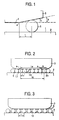
- Fig. 1 illustrates a first embodiment of the present invention. Wherein the parts are the same as those of the related art linear guide apparatus of Figs. 16 to 18, the same numerals are used and their description will be omitted.
- a slider 3 which makes relative movement along the axis of a guide rail 2 with rolling elements 5 has a linear crowning 11 disposed at both ends thereof.
- Both the right and left linear crownings 11 have the same shape and a constant inclination angle ⁇ .
- t is the same as the diameter Da of the rolling element 5.
- separator 12 include a gathering of separated separators 12 and a series combination of separators 12. Either of these separators 12 maybe used. These separators 12 may occasionally have no rolling element 5 present on some portion of the ends thereof. However, this portion free of rolling element accounts for a small proportion in the total area and thus can be neglected.
- the rolling element 5 disposed leftmost among the rolling elements 5 in the left crowning is designated as R1.
- FIG. 5 An example of the relationship between ⁇ L1 and F L1 F R1 , F R2 and Fs is shown in Fig. 5.
- ⁇ L1 changes, Fs changes.
- Fs changes.
- the maximum value of the axial load applied on the slider 3 by one of the rolling elements 5 at the crowning portion is defined to be Fmax.
- Fmax is Q 0 ⁇ .
- Figs. 7 and 8 each illustrate the change of Fsmax/Fmax with L CL .
- Fig. 7 illustrates the case where 0 ⁇ S ⁇ 0.370t.
- Fig. 8 illustrates the case where 0.370t ⁇ S ⁇ t.
- the relationship Fsmax ⁇ Fmax can be established if the following relationship is satisfied.
- the maximum value of the axial load applied on the slider 3 can be predetermined to be smaller than the maximum value of the axial load applied on the crowning portion by one of the rolling elements. 0 ⁇ S ⁇ L CL
- Fsmax/Fmax can be predetermined minimum when L CL is 2.70S.
- the preload amount ⁇ 0 varies with the proper ties (rigidity, magnitude of sliding resistance, etc.) required for rolling linear guide apparatus. It is preferred that the aforementioned relationship be satisfied even for different ⁇ 0 values by the use of a slider having the same crowning shape. This is because the number of kinds of sliders to be designed and produced can be reduced.
- the preload amount ⁇ 0 in the linear guide apparatus is normally not smaller than 0.0002Da.
- the relationship Fsmax ⁇ Fmax is established if ⁇ 0 is not greater than 0.0002Da. 0 ⁇ ⁇ ( N ⁇ t - Le ) ⁇ 0.0002 Da
- the preload amount ⁇ 0 in the linear guide apparatus is normally not smaller than 0.0001Da.
- the relationship Fsmax ⁇ Fmax is established with any ⁇ 0 of not greater than 0.0001Da. 0 ⁇ ⁇ ( N ⁇ t - Le ) ⁇ 0.0001 Da
- Fsmax/Fmax may be predetermined to be minimum.
- the guide rail 2 has two lines of rolling-element rolling grooves 1 provided on both sides thereof and the slider 3 has a linear crowning 11 provided on both moving ends thereof.
- the rolling element 5 is a ball.
- the contact angle ⁇ is 50°.
- Le is then selected from the aforementioned ranges (e.g., 44 mm).
- the relationship Fsmax ⁇ Fmax can be established for any ⁇ 0 of not smaller than 0.0001Da, i.e., not smaller than 0.556 ⁇ m.
- t falls within the aforementioned range
- Fsmax ⁇ Fmax can be established for any ⁇ 0 of not smaller than 0.0002Da, i.e., not smaller than 1.11 ⁇ m.
- the relationship (6) can be deformed to the following relationship: N ⁇ t -0.370 t ⁇ Le ⁇ N ⁇ t and N ⁇ t - ⁇ eL ⁇ 0 ⁇ ⁇ Le ⁇ N ⁇ t - ⁇ eL ⁇ 0 ⁇
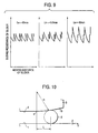
- Fig. 9 The results (numerical analysis) of examination of change of sliding resistance with the movement of the slider 3 for Le of 43 mm, 43.5 mm and 45 mm are shown in Fig. 9.
- the abscissa indicates the moving distance of the slider 3 and the ordinate indicates the sliding resistance of the slider 3.
- the Le value of 43mm gives minimum Fsmax/Fmax. Therefore, the variation of sliding resistance is particularly small.
- the preload amount in the linear guide apparatus is variously predetermined depending on the working conditions.
- Example 1-3 in order to secure similar Fsmax/Fmax when the preload amount varies, it is necessary that the length of the non-crowning portion Le be changed. However, this approach is undesirable from the standpoint of production and stock control. Therefore, it is arranged such that the distance t between the center of the adjacent rolling elements varies with preload amount by disposing a separator 12 interposed between the rolling elements 5.
- the separator 12 can be easily mass-produced by injection molding or like methods. Even separators 12 having different thicknesses can be easily controlled in production and stock.
- ⁇ eL and ⁇ eL are 0.138 and 0.658, respectively, as set forth in Table 1.
- the value of t is selected from the aforementioned ranges .
- the value of t is preferably as small as possible. This is because when the number of rolling elements in the rolling-element rolling grooves 1 and 4 increases, the load capacity increases. Further, the closer to ts the value of t is, the smaller can be Fsmax/Fmax. For example, when t is 5. 9 mm, Fsmax/Fmax can be predetermined to be smaller than 80% .
- Fsmax/Fmax can be predetermined to be smaller than 80%.
- Fsmax can be predetermined to be smaller than e for ⁇ 0 of from not smaller than ⁇ min to not greater than ⁇ max.
- t is then selected from the aforementioned ranges. For example, t is determined to be 5.9 mm. Then, Fsmax/Fmax can be predetermined to be smaller than 80%. As mentioned above, even when a slider 3 and a separator having the same dimension are used and different preload amounts are used, Fsmax/Fmax can be predetermined to be within the same range.
- Fig. 10 illustrates a second embodiment of the present invention which is an arc crowning 13.
- the arc crowning 13 comprises a right portion and a left portion having the same shape and a constant radius R.
- the arc crowning 13 similarly to the aforementioned linear crowning 11.
- the number of rolling elements given a load at the crowning portion is 1 or less, i.e., L CR ⁇ t (Fig. 2).
- F L1 , F R1 and F R2 are represented by the following equations :
- ⁇ L1 and F L1 , F R1 , F R2 and Fs is shown in Fig. 11.
- the maximum value of the axial load applied on the slider 3 by one of the rolling elements in the crowning portion is defined to be Fmax.
- Fmax is represented by the following equation: F max ⁇ 3 3 Q 0 L CR 16 R
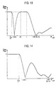
- Figs. 13 and 14 each illustrate the change of Fsmax/Fmax with L CR .
- Fig. 13 illustrates the case of 0 ⁇ S ⁇ 0.5t.
- Fig. 4 illustrates the case of 0.5t ⁇ S ⁇ t.
- Figs. 13 and 14 each illustrate only the case where 0 ⁇ L CR ⁇ 2t. However, even when L CR falls outside this range, the relationship Fsmax ⁇ Fmax can be established at L CR of not smaller than t regardless of L CR .
- Fsmax can be predetermined to be smaller than Fmax.
- the maximum value of the axial load acted on the slider 3 can be predetermined to be smaller than the maximum value of the axial load applied on the slider by one rolling element at the crowning portion.
- L CR 1.02( S + M ⁇ t ) (M: integer of not smaller than 0)
- Fsmax can be predetermined to be smaller than Fmax.
- e and ⁇ eR , ⁇ eR is set forth in Table 2 .
- Table 2 The relationship between e and ⁇ eR , ⁇ eR is set forth in Table 2 .
- e when e is 80%, the following relationship is established: 0.693 2 R ⁇ 0 ⁇ N ⁇ t - Le ⁇ 1.29 2 R ⁇ 0 Table 2 e ⁇ eL ⁇ eL 100% 0.5 1.5 90% 0.635 1.36 80% 0.693 1.29 70% 0.737 1.24 60% 0.776 1.20 50% 0.811 1.15 40% 0.844 1.12 30% 0.877 1.08 20% 0.910 1.04 10% 0.946 1.01
- the guide rail 2 has two lines of rolling-element rolling grooves 1 provided on both sides thereof and the slider 3 has an arc crowning 13 provided on both moving ends thereof.
- the rolling element 5 is a ball.
- the contact angle ⁇ is 50°.
- Le is then selected from the aforementioned ranges (e.g., 47 mm).
- the relationship Fsmax ⁇ Fmax can be established for any ⁇ 0 of not smaller than 0.002Da, i.e., not smaller than 1.11 ⁇ m.
- the relationship Fsmax ⁇ Fmax can be established.
- the relationship (16) can be deformed to the following relationship: 1 N ( ⁇ eR 2 R ⁇ 0 + Le ) ⁇ t ⁇ 1 N ( ⁇ eR 2 R ⁇ 0 + Le )
- Fig. 15 The results (numerical analysis) of examination of change of sliding resistance with the movement of the slider 3 for t of 6.0 mm, 6.1 mm and 6.4 mm are shown in Fig. 15.
- the abscissa indicates the moving distance of the slider 3 and the ordinate indicates the sliding resistance of the slider 3.
- the t value of 6.0 mm is close to 5.99 mm, which value gives minimum Fsmax/Fmax. Therefore, the variation of sliding resistance is particularly small.
- Fsmax/Fmax can be predetermined to be smaller than e for ⁇ 0 of from not smaller than ⁇ min to not greater than ⁇ max.
- t is then selected from the aforementioned ranges. For example, t is determined to be 5.9 mm. Then, Fsmax/Fmax can be predetermined to be smaller than 80%.
- the elastic deformation of rolling element unloaded.
- the elastic deformation ⁇ 1 of rolling element under the conditions that the reduction of variation of slidingresistance is important may be used instead of ⁇ 0 .
- the elastic deformation ⁇ 1 of rolling element by its own weight may be used.
- the magnitude of the axial load applied on one rolling element by the crowning portion can be obtained as a function of position ⁇ of rolling element. Accordingly, ⁇ , is plotted as abscissa and F as ordinate. From this graph can be determined the maximum value Fmax of axial load F applied on the slide by one rolling element.
- the number of rolling elements given a load in the crowning portion is 1 or less, i.e., LCR ⁇ t, similarly to the case of linear and arc crownings.
- the load in the axial direction applied on the slider at the right and left crowning portions cancel each other.
- the axial load acted on the slider can be predetermined to be smaller than the maximum value of the axial load applied on the slider by one rolling element at one of the crowning portions. In other words, the change of the sliding resistance of the slider can be reduced.
Landscapes
- Engineering & Computer Science (AREA)
- General Engineering & Computer Science (AREA)
- Mechanical Engineering (AREA)
- Bearings For Parts Moving Linearly (AREA)
- Rolling Contact Bearings (AREA)
Abstract
Description
- The present invention relates to a linear guide apparatus for use in machine tools, industrial machines, etc.
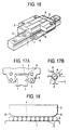
- A linear guide apparatus as a linear guide for use in machining center as machine tool, robot as industrial machine, etc. has been known. As shown in Figs. 16, 17A and 17B, this linear guide apparatus comprises a
guide rail 2 having a rolling-element rolling groove 1 formed on both sides thereof in the axial direction and aslider 3 which fits in theguide rail 2. Provided on the inner surface of theslider 3 is a rolling-element rolling groove 4 disposed opposed to the rolling-element rolling groove 1 of theguide rail 2. A number ofrolling elements 5 are rollably interposed between the rolling-element rolling grooves slider 3 makes relative movement with therolling elements 5 along the axis of theguide rail 2. - In this linear guide apparatus, the
slider 3 has anend cap 6 provided on both axial ends thereof. Theend cap 6 has a circulating path 7 forming a curved path communicating to the rolling-element rolling grooves - As shown in Fig. 18, the
slider 3 may have a slow inclination calledcrowning portion 8 provided at both ends thereof for relaxing stress concentration. It is known that the provision of the crowningportion 8 makes it possible to enhance durability. On the other hand, the crowningportion 8 has an effect on the degree of change of sliding resistance of theslider 3 of the linear guide apparatus during movement. This change of sliding resistance has an adverse effect on the performance of machines comprising the linear guide apparatus. For example, the positioning properties of the machines are deteriorated to disadvantage. It has thus been desired to reduce the change of sliding resistance. - However, the selection of the crowning form for inhibiting the change of sliding resistance has heretofore been often experimentally made. Therefore, in order to realize a rolling linear guide having a reduced change of sliding resistance, production on trial basis and experiments must be repeated, requiring much labor.
- The present invention has been worked out under these circumstances. An aim of the present invention is to a linear guide apparatus which has a reduced change of axial component of contact load of slider at crowning portion with movement of rolling element to exhibit a reduced change of sliding resistance.
- Another aim of the present invention is to provide a linear guide apparatus suitable for use in uses requiring a reduced change of sliding resistance such as electric discharge machine, mold processing machine, drawing device, semiconductor producing machine (exposing device) and precision measuring instrument.
- In order to accomplish the aforementioned aims of the present invention, the present invention lies in a linear guide apparatus having a guide rail having a rolling-element rolling groove formed on a side thereof along in an axial direction, and a slider having a rolling-element rolling groove disposed so as to be opposed to the rolling-element rolling groove of the guide rail, the slider moving relatively in the axial direction of the guide rail with rolling elements rollably interposed between the two rolling-element rolling grooves, and a crowning portion disposed on the both axial ends of the rolling-element rolling groove of the slider, wherein a maximum value of sum of load in an axial direction applied on the crowing portion on the both axial ends of the slider by the rolling elements is set to be smaller than a maximum value of load in the axial direction applied on one of the crowning portions of the slider by one rolling element.
- In other words, the linear guide apparatus is arranged such that the load in the axial direction applied on the rolling elements at the right and left crowning portions cancel each other. In this arrangement, the sum of the load applied on the rolling elements at the right and left crowning portions is set to be smaller than the maximum value of the load in the axial direction applied on the slider at one of the crowning portions by the rolling elements.
- At the portion free of crowning portion, the direction of contact load of rolling element with the rolling groove is perpendicular to the axial direction. Therefore, the contact load at this portion has no axial component.
- However, at the portion having a crowning portion, the contact load of rolling element with the rolling groove has a axial component. The magnitude of this axial component normally changes with the movement of the rolling elements. This is attributed to the fact that the arrangement of the crowning portion causes the change of the rolling elements and the rolling groove and hence the change of the contact load and the direction of contact of the rolling elements with the rolling groove changes.
- The change of the axial load generated at the crowning portion causes the sum of the load in the axial direction applied on the slider by the crowning portion at both ends to change with the movement of the slider (i.e., movement of the rolling elements). This change of the load in the axial direction directly leads to the change of the sliding resistance of the slider.
- In accordance with the present invention, these axial loads can cancel each other at the right and left crowning portions. In this arrangement, the axial load acted on the slider can be predetermined to be smaller than the maximum value of the load in the axial direction applied on the slider at one of the crowning portions. In other words, the change of the sliding resistance of the slider can be reduced.
- In addition to this, according to the present invention, it is preferable that a linear guide apparatus having a guide rail having a rolling-element rolling groove formed on a side thereof along in an axial direction, a slider having a rolling-element rolling groove disposed so as to be opposed to the rolling-element rolling groove of the guide rail, the slider moving relatively in the axial direction of the guide rail with rolling elements rollably interposed between the two rolling-element rolling grooves, and a crowning portion disposed on the both axial ends of the slider, wherein the crowning portion is a linear crowning having a constant inclination angle θ and satisfying the following relationship:

- Further, according to the present invention, it is preferable that a linear guide apparatus having a guide rail having a rolling-element rolling groove formed on a side thereof along in an axial direction, and a slider having a rolling-element rolling groove disposed so as to be opposed to the rolling-element rolling groove of the guide rail, the slider moving relatively in the axial direction of the guide rail with rolling elements rollably interposed between the two rolling-element rolling grooves, and a crowning portion disposed on the both axial ends of the slider, wherein the crowning portion is an arc crowning having a constant radius R and satisfying any of the following relationships (1) to (3) :


-
- Fig. 1 is a longitudinal section of a linear crowning according to a first embodiment of the present invention;
- Fig. 2 is a diagram of the first embodiment of the present invention illustrating the state that the center of rolling element L1 is positioned at the left crowning starting point;
- Fig. 3 is a diagram of the first embodiment of the present invention wherein a separator is disposed between the rolling elements;
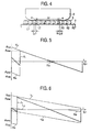
- Fig. 4 is a diagram of the first embodiment of the present invention illustrating the state that the various rolling elements have moved leftward by ξL1;
- Fig. 5 is a diagram of the first embodiment of the present invention illustrating the axial load applied on the slider;
- Fig. 6 is a diagram of the first embodiment of the present invention illustrating the axial load applied on the slider;
- Fig. 7 is a diagram of the first embodiment of the present invention illustrating the change of Fsmax/Fmax with LCL;
- Fig. 8 is a diagram of the first embodiment of the present invention illustrating the change of Fsmax/Fmax with LCL;
- Fig. 9 is a graph of the first embodiment of the present invention illustrating the results of the change of sliding resistance with the movement of the slider;
- Fig. 10 is a longitudinal section of a second embodiment of the present invention illustrating an arc crowning;
- Fig. 11 is a diagramof the second embodiment of the present invention illustrating the axial load applied on the slider;
- Fig. 12 is a diagram of the second embodiment of the present invention illustrating the axial load applied on the slider;
- Fig. 13 is a diagramof the second embodiment of the present invention illustrating the change of Fsmax/Fmax with LCR;
- Fig. 14 is a diagramof the second embodiment of the present invention illustrating the change of Fsmax/Fmax with LCR;
- Fig. 15 is a graph of the second embodiment of the present invention illustrating the results of the change of sliding resistance with the movement of the slider;
- Fig. 16 is a partially cut away perspective view of a related art linear guide apparatus;
- Figs. 17A and 17B illustrate linear guide apparatus wherein Fig. 17A is a transverse sectional view of the linear guide apparatus and Fig. 17B is an enlarged view of part A of Fig. 17A; and
- Fig. 18 is a diagram illustrating a crowning portion of the linear guide apparatus of Figs. 17A and 17B.
- Embodiments of implementation of the present invention will be described hereinafter in connection with the attached drawings.
- Fig. 1 illustrates a first embodiment of the present invention. Wherein the parts are the same as those of the related art linear guide apparatus of Figs. 16 to 18, the same numerals are used and their description will be omitted. As shown in Fig. 1, a
slider 3 which makes relative movement along the axis of aguide rail 2 with rollingelements 5 has a linear crowning 11 disposed at both ends thereof. - Both the right and left
linear crownings 11 have the same shape and a constant inclination angle θ. The rollingelement 5 acts as a ball crowning. Supposing that the distance in the axial direction from the crowning starting point a over the rollingelement 5 of thelinear crowning 11 is ξ, the following equation is established.

wherein θ: Angle of inclination of crowning - δ0: Preload amount of rolling element at portion free of crowning on race when unloaded (diameter of rolling element based on the diameter of rolling element which gives zero elastic deformation)
- kn: Constant determined by Hertz's theory


- Among the rolling
elements 5 disposed in thelinear crowning 11, only the rollingelements 5 satisfying the relationship ξ ≤ LCL are given a load. Let us firstly suppose the case where the maximum number of the rollingelements 5 given a load at the linear crowing 11 is 1, i.e., LCL ≤ t. - Let us then suppose the state that the center of the rolling element L1 is positioned at the left crowning starting point a as shown in Fig. 2. The rolling
elements 5 juxtaposed in the rolling-element rolling grooves elements 5 with aseparator 12, if any, interposed between the rolling elements (as shown in Fig. 13). - In the case where there is no
separator 12 disposed between the rolling elements 5 (as shown in Fig. 2), t is the same as the diameter Da of the rollingelement 5. Examples of theseparator 12 include a gathering of separatedseparators 12 and a series combination ofseparators 12. Either of theseseparators 12 maybe used. Theseseparators 12 may occasionally have no rollingelement 5 present on some portion of the ends thereof. However, this portion free of rolling element accounts for a small proportion in the total area and thus can be neglected. - In the state shown in Fig. 3, the rolling
element 5 disposed leftmost among the rollingelements 5 in the left crowning is designated as R1. The distance S from the center of the rolling element R1 to the right crowning starting point a is calculated by the following equation:
- Let us next suppose the state that the various rolling
elements 5 each move leftward by ξL1 (as shown in Fig. 4) . The disposition of the rollingelements 5 occurring when ξL1 rises to t is the same as that occurring when ξL1 is zero. Accordingly, the range of ξL1 may be considered to be 0 ≤ ξL1 ≤ t. - When ξL1 satisfies the relationship 0 ≤ξL1≤t, three rolling elements L1, R1 and R2 give an axial load to the
slider 3. The axial loads FL1, FR1 and FR2 applied on theslider 3 by the rollingelements 5 are represented by the following equations with the proviso that the rightward load is positive:


- The sum Fs of the axial loads applied on the
slider 3 is represented by the following equation:
- An example of the relationship between ξL1 and FL1 FR1, FR2 and Fs is shown in Fig. 5. As ξL1 changes, Fs changes. In other words, as the rolling
elements 5 move, the axial load given by the crowning portion changes. This change directly leads to the change of sliding resistance. The maximum value of the axial load applied on theslider 3 by one of the rollingelements 5 at the crowning portion is defined to be Fmax. Fmax is Q0θ. - Let us next suppose the case where the maximum number of the rolling
elements 5 given a load at the crowning portion is 2 or more (LCL > t) . Let us suppose the case where t < LCL ≤ 2t by way of example. When ξL1 satisfies the relationship 0 ≤ ξL1 ≤ t five rolling elements L1, L2, R1, R2 and R3 give an axial load to theslider 3. The axial loads FL1, FL2, FR1, FR2 and FR3 applied on the slider by the rolling elements are shown in Fig. 6. Fig. 6 shows the sum Fs of the axial loads applied on the slider. - Figs. 7 and 8 each illustrate the change of Fsmax/Fmax with LCL. Fig. 7 illustrates the case where 0 < S < 0.370t. Fig. 8 illustrates the case where 0.370t ≤S < t. By selecting proper LCL, the relationship Fsmax < Fmax can be established. This is because when LCL is proper, the axial load given at the right and left crowning portions cancel each other.
- When S is zero, the relationship Fsmax = Fmax can be established regardless of LCL. Figs. 7 and 8 each illustrate only the case where 0 ≤ LCL ≤ 2t. However, even when LCL falls outside this range, if S is not zero, the relationship Fsmax < Fmax can be established at LCL of not smaller than t regardless of LCL.
- As can be seen in Figs. 7 and 8, the relationship Fsmax < Fmax can be established if the following relationship is satisfied. In other words, the maximum value of the axial load applied on the
slider 3 can be predetermined to be smaller than the maximum value of the axial load applied on the crowning portion by one of the rolling elements.
- Further, in the case where 0 < S < 0.370t, Fsmax/Fmax can be predetermined minimum when LCL is 2.70S.
- The relationship (1) and the definition of S and LCL make it possible to establish the relationship Fsmax < Fmax if there is an integer N satisfying the following relationship:

- The preload amount δ0 varies with the proper ties (rigidity, magnitude of sliding resistance, etc.) required for rolling linear guide apparatus. It is preferred that the aforementioned relationship be satisfied even for different δ0 values by the use of a slider having the same crowning shape. This is because the number of kinds of sliders to be designed and produced can be reduced.
- Among uses requiring that the variation of sliding resistance be small, uses subject to varying load such as mold processing machine require some rigidity. In such uses, the preload amount δ0 in the linear guide apparatus is normally not smaller than 0.0002Da. As can be seen in the relationship (2), when there is an integer N satisfying the relationship, the relationship Fsmax < Fmax is established if δ0 is not greater than 0.0002Da.

- On the other hand, uses requiring accurate position control such as semiconductor producing machine (exposing device) and precision measuring instrument require that the variation as well as the absolute value of sliding resistance be small. In such uses, the preload amount δ0 in the linear guide apparatus is normally not smaller than 0.0001Da. As can be seen in the relationship (2), when there is an integer N satisfying the relationship, the relationship Fsmax < Fmax is established with any δ0 of not greater than 0.0001Da.

- In order to reduce the variation of sliding resistance in particular, Fsmax/Fmax may be predetermined to be minimum. As can be seen in Fig. 7, the conditions under which Fsmax/Fmax is minimum (0.5) give the following relationships:

- It is normally difficult to strictly satisfy the relationship (5) due to restrictions such as error inprocessing. Let us then examine the conditions under which Fsmax/Fmax is smaller than e. These conditions give the following relationships:


Table 1 e βeL γeL 100% 0 1 90% 0.0678 0.785 80% 0.138 0.658 70% 0.212 0.552 60% 0.289 0.457 - Explaining next specific examples of the linear guide apparatus, the
guide rail 2 has two lines of rolling-element rolling grooves 1 provided on both sides thereof and theslider 3 has a linear crowning 11 provided on both moving ends thereof. The rollingelement 5 is a ball. The contact angle α is 50°. - Le satisfying the relationship Fsmax < Fmax for any δ0 of not smaller than 0.0001Da
- Ball diameter: Da = 5.56 mm
- Inclination of crowning: θ = 0.001rad
- Distance between the center
- of adjacent rolling elements: t = 5.56 mm (free of separator)
- The relationship (4) can be deformed to the following relationship:

- Substituting various values for the factors in the foregoing relationship gives the following relationships for the range of Le:


- Le is then selected from the aforementioned ranges (e.g., 44 mm). As a result, the relationship Fsmax < Fmax can be established for any δ0 of not smaller than 0.0001Da, i.e., not smaller than 0.556 µm.
-
- t satisfying the relationship Fsmax < Fmax for any δ0 of not smaller than 0.0002Da
- Ball diameter: Da = 5.56 mm
- Inclination of crowning: θ = 0.001rad
- Length of non-crowning portion: Le = 46 mm
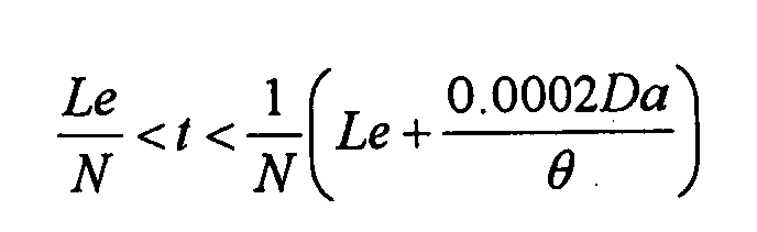
- The relationship (3) can be deformed to the following relationship:


- The thickness of the
separator 12 is then predetermined such that t falls within the aforementioned range (e.g., t = 5.8 mm). As a result, the relationship Fsmax < Fmax can be established for any δ0 of not smaller than 0.0002Da, i.e., not smaller than 1.11 µm. -
- Ball diameter: Da = 5.56 mm
- Inclination of crowning: θ = 0.001rad
- Distance between the center
- of adjacent rolling elements: t = 5.56 mm (free of separator)
- Preload amount: δ0 = 0.004 mm
- The conditions (2) under which the relationship Fsmax < Fmax is established can be deformed to the following relationships:

- Substituting various values for the factors in the foregoing relationship gives the following relationships:


- By properly selecting Le from the aforementioned ranges, the relationship Fsmax < Fmax can be established.
- Let us next consider the range within which the relationship Fsmax/ Fmax <70% is established. The relationship (6) can be deformed to the following relationship:

- When e is 70%, βeL and γeL are 0.212 and 0.552, respectively, as set forth in Table 1. Substituting various values for the factors in the'foregoing relationships gives the following relationships for the range of Le. The Le value (Les) which gives minimum Fsmax/Fmax can be determined by the relationship (5).


- By properly selecting Le from the aforementioned ranges, the relationship Fsmax/Fmax < 70% can be established.
- The closer to Les Le is, the smaller can be Fsmax/Fmax.
- The results (numerical analysis) of examination of change of sliding resistance with the movement of the
slider 3 for Le of 43 mm, 43.5 mm and 45 mm are shown in Fig. 9. In Fig. 9, the abscissa indicates the moving distance of theslider 3 and the ordinate indicates the sliding resistance of theslider 3. - When Le is 45 mm, the relationship Fsmax < Fmax cannot be satisfied.
- When Le is 43 mm or 43.5 mm, the relationship Fsmax/Fmax < 70% can be satisfied.
- The Le value of 43mm gives minimum Fsmax/Fmax. Therefore, the variation of sliding resistance is particularly small.
- As mentioned above, the advantage of the present invention can be confirmed.
- The preload amount in the linear guide apparatus is variously predetermined depending on the working conditions. In Example 1-3, in order to secure similar Fsmax/Fmax when the preload amount varies, it is necessary that the length of the non-crowning portion Le be changed. However, this approach is undesirable from the standpoint of production and stock control. Therefore, it is arranged such that the distance t between the center of the adjacent rolling elements varies with preload amount by disposing a
separator 12 interposed between therolling elements 5. Theseparator 12 can be easily mass-produced by injection molding or like methods. Even separators 12 having different thicknesses can be easily controlled in production and stock. - Ball diameter: Da = 5.56 mm
- Inclination of crowning: θ = 0.001rad
- Length of non-crowning portion: Le = 46 mm
- Preload amount: δd = 0.004 mm
- Let us next consider the conditions under which the relationship Fsmax/Fmax < 80% is established. The relationship (6) can be deformed to the following relationships :

- When e is 80%, βeL and γeL are 0.138 and 0.658, respectively, as set forth in Table 1. Le us next substitute various values for the factors in these relationships. Since t is not smaller than Da, the following relationships can be established for the range of t. The value of t (ts) which gives minimum Fsmax/Fmax can be determined by the relationship (5).


- The value of t is selected from the aforementioned ranges . The value of t is preferably as small as possible. This is because when the number of rolling elements in the rolling-
element rolling grooves - Let us next suppose that the preload amount δ0 is 0.001 mm. In this case, too, the following relationships are established for the range of t and the value of ts:



- The value of t is then selected from the aforementioned ranges. For example, when t is 5.8 mm, Fsmax/Fmax can be predetermined to be smaller than 80%.
- As mentioned above, when
separators 12 having different dimensions are used, similar Fsmax/Fmax values can be obtained even if different preload amounts are used with thesame slider 3. - In Examples 1-3 and 1-4,
sliders 3 orseparators 12 having different dimensions were required. However, when the range of preload amount is previously known, aslider 3 and aseparator 12 having the same dimension can be used to predetermine Fsmax/Fmax to be within a required range. This is advantageous in production and stock control. - Ball diameter: Da = 5.56 mm
- Inclination of crowning: θ = 0.001rad
- Length of non-crowning portion: Le = 46 mm
- Minimum preload amount: δmin = 0.002 mm
- Maximum preload amount: δmax = 0.008 mm
- As can be seen in the relationship (6), when the following relationships are satisfied, Fsmax can be predetermined to be smaller than e for δ0 of from not smaller than δmin to not greater than δmax.

- When e is 80%, βeL and γeL are 0.138 and 0.658, respectively, as set forth in Table 1. Let us next substitute various values for the factors in the aforementioned relationships. As a result, the following relationships are established for the range of t:


- The value of t is then selected from the aforementioned ranges. For example, t is determined to be 5.9 mm. Then, Fsmax/Fmax can be predetermined to be smaller than 80%. As mentioned above, even when a
slider 3 and a separator having the same dimension are used and different preload amounts are used, Fsmax/Fmax can be predetermined to be within the same range. - In the case where βeL δmax is not smaller than γeLδmin, when the preload amount falls within a required range, Fsmax/Fmax cannot be predetermined to be smaller than e with the same value of t. In this case, it is necessary that a plurality of kinds of separators having different values of t be prepared.
- Fig. 10 illustrates a second embodiment of the present invention which is an
arc crowning 13. The arc crowning 13 comprises a right portion and a left portion having the same shape and a constant radius R. The rollingelement 5 is a ball. Supposing that the distance of the rollingelement 5 in the arc crowning 13 from the crowning starting point a is ξ, the following relationships are established:


wherein - R: Radius of crowning portion
- δ0: Elastic deformation of ball at crowning-free portion on race when unloaded
- kn: Constant determined by Hertz's theory


- Let us consider hereinafter the arc crowning 13 similarly to the aforementioned
linear crowning 11. Let us firstly suppose the case where the number of rolling elements given a load at the crowning portion is 1 or less, i.e., LCR ≤ t (Fig. 2). Let us consider 0 ≤ ξL1 ≤ t. The rolling elements giving an axial load to theslider 3 are rolling elements L1, R1 and R2. Supposing that the distance of the rolling element L1 from the left crowning starting point is ξL1, the axial load Fs applied on theslider 3 is represented by the following equation:
- FL1, FR1 and FR2 are represented by the following equations :


- The relationship between ξL1 and FL1, FR1, FR2 and Fs is shown in Fig. 11. The maximum value of the axial load applied on the
slider 3 by one of the rolling elements in the crowning portion is defined to be Fmax. Fmax is represented by the following equation:
- Let us next consider the case where there are two or more
rolling elements 5 given a load at the crowning portion (LCR > t) . Let us consider the case of t < LCR ≤ 2t by way of example. When ξL1 falls within the range of from not smaller than 0 to not greater than t, the five rolling elements L1, L2, R1, R2 and R3 give a load in the axial direction. The axial loads FL1, FL2, FR1, FR2 and FR3 applied on theslider 3 by the rollingelements 5 are shown in Fig. 12. Fig. 12 indicates the sum Fs of axial loads applied on theslider 3. - Figs. 13 and 14 each illustrate the change of Fsmax/Fmax with LCR. Fig. 13 illustrates the case of 0 ≤ S ≤ 0.5t. Fig. 4 illustrates the case of 0.5t < S < t. Figs. 13 and 14 each illustrate only the case where 0 ≤ LCR ≤ 2t. However, even when LCR falls outside this range, the relationship Fsmax < Fmax can be established at LCR of not smaller than t regardless of LCR.
- As shown in Figs. 13 and 14, when any of the clauses (1) to (3) of the relationship (11) is satisfied, Fsmax can be predetermined to be smaller than Fmax. In other words, the maximum value of the axial load acted on the
slider 3 can be predetermined to be smaller than the maximum value of the axial load applied on the slider by one rolling element at the crowning portion.


- Further, when the following relationships are satisfied, Fsmax/Fmax becomes minimum.
- The minimum value is substantially zero.

- Accordingly, when any of the clauses (1) to (3) of the following relationship (12) is satisfied, Fsmax can be predetermined to be smaller than Fmax.


- The following relationships are established as in the case of linear crowning.
- Conditions under which Fsmax < Fmax is established in uses requiring some rigidity (0.0002Da ≤ δ0):

- Conditions under which Fsmax < Fmax is established in uses requiring a small sliding resistance (0.0001Da ≤ δ0):

- Conditions under which Fsmax/Fmax is minimum:

- Conditions under which Fsmax/Fmax is smaller than e:

- The relationship between e and βeR, γeR is set forth in Table 2 . For example, when e is 80%, the following relationship is established:

Table 2 e βeL γeL 100% 0.5 1.5 90% 0.635 1.36 80% 0.693 1.29 70% 0.737 1.24 60% 0.776 1.20 50% 0.811 1.15 40% 0.844 1.12 30% 0.877 1.08 20% 0.910 1.04 10% 0.946 1.01 - Explaining next specific examples of the linear guide apparatus, the
guide rail 2 has two lines of rolling-element rolling grooves 1 provided on both sides thereof and theslider 3 has an arc crowning 13 provided on both moving ends thereof. The rollingelement 5 is a ball. The contact angle α is 50°. - Le satisfying the relationship Fsmax < Fmax for any δ0 of not smaller than 0.0002Da
- Ball diameter: Da = 5.56 mm
- Radius of crowning: R = 2,000 mm
- Distance between the center
- of adjacent rolling elements: t = 5.56 mm (free of separator)
- The relationship (13) can be deformed to the following relationship:

- Substituting various values for the factors in the foregoing relationship gives the following relationships for the range of Le:


- Le is then selected from the aforementioned ranges (e.g., 47 mm). As a result, the relationship Fsmax < Fmax can be established for any δ0 of not smaller than 0.002Da, i.e., not smaller than 1.11 µm.
-
- Ball diameter: Da = 5.56 mm
- Radius of crowning: R = 2,000 mm
- Length of non-crowning portion: Le = 44 mm
- Preload amount: δ0 = 0.004 mm
- The conditions (12) under which the relationship Fsmax < Fmax is established can be deformed to the following relationships:

- Substituting various values for the factors in the aforementioned relationship gives the following relationships because t is smaller than Da:


- By properly selecting t from the aforementioned ranges, the relationship Fsmax < Fmax can be established. Let us next consider the range within which the relationship Fsmax/Fmax < 60% is established. The relationship (16) can be deformed to the following relationship:

- When e is 60%, βeR and γeR are 0.776 and 1.20, respectively, as set forth in Table 2. Substituting various values for the factors in the foregoing relationships gives the following relationships for the range of t. The Le value (ts) which gives minimum Fsmax/Fmax can be determined by the relationship (15).


- By properly selecting t from the aforementioned ranges, the relationship Fsmax/Fmax < 60% can be established. The closer to ts t is, the smaller can be Fsmax/Fmax.
- The results (numerical analysis) of examination of change of sliding resistance with the movement of the
slider 3 for t of 6.0 mm, 6.1 mm and 6.4 mm are shown in Fig. 15. In Fig. 15, the abscissa indicates the moving distance of theslider 3 and the ordinate indicates the sliding resistance of theslider 3. - When t is 6.4 mm, the relationship Fsmax < Fmax cannot be satisfied. The variation of sliding resistance is great.
- When t is 6.0 mm or 6.1 mm, the relationship Fsmax/Fmax < 60% can be satisfied. The variation of sliding resistance is great.
- The t value of 6.0 mm is close to 5.99 mm, which value gives minimum Fsmax/Fmax. Therefore, the variation of sliding resistance is particularly small.
- As mentioned above, the advantage of the present invention can be confirmed.
- The relationship Fsmax/Fmax < 80% is then secured.
- Ball diameter: Da = 5.56 mm
- Radius of crowing: R = 1,000 mm
- Length of non-crowning portion: Le = 46 mm
- Minimum preload amount: δmin = 0.002 mm
- Maximum preload amount: δmax = 0.006 mm
- As can be seen in the relationship (16), when the following relationship is satisfied, Fsmax/Fmax can be predetermined to be smaller than e for δ0 of from not smaller than δmin to not greater than δmax.

- When e is 80%, βeL and γeL are 0.693 and 1.29, respectively, as set forth in Table 2. Let us next substitute various values for the factors in the aforementioned relationship. As a result, the following relationships are established for the range of t:


- The value of t is then selected from the aforementioned ranges. For example, t is determined to be 5.9 mm. Then, Fsmax/Fmax can be predetermined to be smaller than 80%.
- In the foregoing embodiments, as preload amount there was used the elastic deformation of rolling element unloaded. In order to further reduce the variation of sliding resistance, the elastic deformation δ1 of rolling element under the conditions that the reduction of variation of slidingresistance is important may be used instead of δ0. For example, in the case where the present invention is applied to machines on which a great external load is not acted such as semiconductor producing device, the elastic deformation δ1 of rolling element by its own weight may be used.
- The aforementioned embodiments have been described with reference to the
linear crowning 11 and the arc crowning 13. The conditions under which the relationship Fsmax < Fmax is established can be similarly found for other crowning forms. - In the case where crowning is represented by a function (y = f (ξ)) of distance ξ from the crowning starting point, the following equations can be established:


wherein δ0: Elastic deformation of ball at crowning-free portion on race when unloaded - kn: Constant determined by Hertz's theory

- As can be seen in the equation (A2), the magnitude of the axial load applied on one rolling element by the crowning portion can be obtained as a function of position ξ of rolling element. Accordingly, ξ, is plotted as abscissa and F as ordinate. From this graph can be determined the maximum value Fmax of axial load F applied on the slide by one rolling element.
- Let us next suppose the case where the number of rolling elements given a load in the crowning portion is 1 or less, i.e., LCR ≤ t, similarly to the case of linear and arc crownings. The rolling elements giving an axial load to the slider are rolling elements L1, R1 and R2. Supposing that the distance of the rolling element L1 from the left crowning starting point is ξL1, the axial load Fs applied on the slider is represented by the following equation:


- From the aforementioned equations (A3) to (A6) can be known the relationship between the coordinate ξL1 of the rolling element L1 and the sum Fs of axial loads applied on the slider. Accordingly, by graphically plotting the relationship between ξL1 and Fs, the maximum value Fsmax of the sum Fs of axial loads applied on the slider can be known.
- The present embodiment has been considered with reference to the case of LCR ≤ t. In the case of LCR > t, too, Fmax and Fsmax can be determined as already described in the case of linear and arc crownings.
- As mentioned above, the maximum value Fmax of axial load applied on the slider by one rolling element and the maximum value Fsmax of the sum of axial loads applied on the slider by the rolling elements for the case where an arbitrary crowning form y = f (ξ) is given can be known. Accordingly, the crowning form y = f (ξ) giving Fmax > Fsmax can be found.
- The present embodiment has been described only with reference to the case where the rolling element is a ball. For the case where the rolling element is a roller, too, the conditions under which Fsmax is smaller than Fmax can be found.
- In the case where the rolling element is a roller, the crowning represented by y = f (ξ) as a function of distance ξ from the crowning starting point can be given the following equations:


wherein - δ0 : Elastic deformation of ball at crowning-free portion on race when unloaded
- kn: Constant determined by Hertz's theory

- The foregoing equations (A7) and (A8) have the same form as the equations (A1) and (A2), in which the rolling element is a ball, except that they have different exponents. Accordingly, the crowning form y = f (ξ) giving Fmax > Fsmax can be found in the same manner as in the case where the rolling element is a ball.
- As mentioned above, in accordance with the present invention, the load in the axial direction applied on the slider at the right and left crowning portions cancel each other. In this arrangement, the axial load acted on the slider can be predetermined to be smaller than the maximum value of the axial load applied on the slider by one rolling element at one of the crowning portions. In other words, the change of the sliding resistance of the slider can be reduced.
Claims (3)
- A linear guide apparatus comprising:a guide rail having a rolling-element rolling groove formed on a side thereof along in an axial direction; anda slider having a rolling-element rolling groove disposed so as to be opposed to the rolling-element rolling groove of the guide rail, the slider moving relatively in the axial direction of the guide rail with rolling elements rollably interposed between the two rolling-element rolling grooves, and a crowning portion disposed on the both axial ends of the rolling-element rolling groove of the slider,wherein a maximum value of sum of load in an axial direction applied on the crowing portion on the both axial ends of the slider by the rolling elements is set to be smaller than a maximum value of load in the axial direction applied on one of the crowning portions of the slider by one rolling element.
- A linear guide apparatus comprising:a guide rail having a rolling-element rolling groove formed on a side thereof along in an axial direction;a slider having a rolling-element rolling groove disposed so as to be opposed to the rolling-element rolling groove of the guide rail, the slider moving relatively in the axial direction of the guide rail with rolling elements rollably interposed between the two rolling-element rolling grooves, and a crowning portion disposed on the both axial ends of the slider,wherein the crowning portion is a linear crowning having a constant inclination angle θ and satisfying the following relationship:
 t represents the distance between centers of the rolling elements (with separator) or a diameter of the rolling element (free of separator);Le represents the length of the non-crowning portion; andδo represents preload amount (diameter of rolling element based on the diameter of rolling element which gives zero elastic deformation at the non-crowning portion).
 - A linear guide apparatus comprising:a guide rail having a rolling-element rolling groove formed on a side thereof along in an axial direction; anda slider having a rolling-element rolling groove disposed so as to be opposed to the rolling-element rolling groove of the guide rail, the slider moving relatively in the axial direction of the guide rail with rolling elements rollably interposed between the two rolling-element rolling grooves, and a crowning portion disposed on the both axial ends of the slider,wherein the crowning portion is an arc crowning having a constant radius R and satisfying any of the following relationships (1) to (3):


 t represents the distance between centers of the rolling elements (with separator) or the diameter of the rolling element (free of separator);Le represents the length of the non-crowning portion; andδo represents preload amount (diameter of rolling element based on the diameter of rolling element which gives zero elastic deformation at the non-crowning portion).
Applications Claiming Priority (4)
| Application Number | Priority Date | Filing Date | Title |
|---|---|---|---|
| JP2002054802 | 2002-02-28 | ||
| JP2002054802 | 2002-02-28 | ||
| JP2002359483A JP4423851B2 (en) | 2002-02-28 | 2002-12-11 | Method for manufacturing linear motion guide device |
| JP2002359483 | 2002-12-11 |
Publications (2)
| Publication Number | Publication Date |
|---|---|
| EP1342929A1 true EP1342929A1 (en) | 2003-09-10 |
| EP1342929B1 EP1342929B1 (en) | 2006-02-08 |
Family
ID=27759719
Family Applications (1)
| Application Number | Title | Priority Date | Filing Date |
|---|---|---|---|
| EP03004318A Expired - Lifetime EP1342929B1 (en) | 2002-02-28 | 2003-02-27 | Linear guide apparatus |
Country Status (4)
| Country | Link |
|---|---|
| US (1) | US6807746B2 (en) |
| EP (1) | EP1342929B1 (en) |
| JP (1) | JP4423851B2 (en) |
| DE (1) | DE60303462T2 (en) |
Families Citing this family (14)
| Publication number | Priority date | Publication date | Assignee | Title |
|---|---|---|---|---|
| DE10347965A1 (en) * | 2003-10-10 | 2005-05-04 | Heidenhain Gmbh Dr Johannes | Safety device for the transport and installation of a measuring device |
| DE10347360B4 (en) * | 2003-10-11 | 2021-07-01 | Robert Bosch Gmbh | Guide with measuring device and method for producing such a guide |
| US20050157962A1 (en) * | 2003-12-02 | 2005-07-21 | Nsk Ltd. | Linear guide apparatus |
| JP4565545B2 (en) | 2004-03-24 | 2010-10-20 | 日本トムソン株式会社 | Linear motion guidance unit |
| WO2005108807A1 (en) | 2004-05-12 | 2005-11-17 | Thk Co., Ltd. | Rolling machine element |
| WO2008036060A2 (en) | 2005-04-05 | 2008-03-27 | Allergan, Inc. | Clostridial toxin activity assays |
| DE102006060609A1 (en) * | 2006-12-21 | 2008-06-26 | AMK Arnold Müller GmbH & Co. KG | Linear rolling bearing element |
| US7585112B2 (en) * | 2007-03-20 | 2009-09-08 | Hiwin Technologies Corp. | Linear motion guide apparatus |
| DE102007042796A1 (en) * | 2007-09-07 | 2009-03-12 | Robert Bosch Gmbh | Guide rail with absolute measuring standard |
| DE102007044642A1 (en) * | 2007-09-19 | 2009-04-02 | Liebherr-Aerospace Lindenberg Gmbh | Aircraft lift augmentation system |
| JP5083054B2 (en) * | 2008-06-10 | 2012-11-28 | 株式会社ジェイテクト | Ball spline |
| CN103851078B (en) * | 2012-11-28 | 2016-06-22 | 全球传动科技股份有限公司 | Motion body of ball motion module and processing method thereof |
| WO2020110754A1 (en) | 2018-11-27 | 2020-06-04 | Thk株式会社 | Motion guidance device |
| JP7553276B2 (en) * | 2020-07-27 | 2024-09-18 | Ntn株式会社 | Bearing device |
Citations (4)
| Publication number | Priority date | Publication date | Assignee | Title |
|---|---|---|---|---|
| GB2142098A (en) * | 1983-05-26 | 1985-01-09 | Hiroshi Teramachi | Linear bearing |
| US4743124A (en) * | 1985-08-02 | 1988-05-10 | Deutsche Star Gmbh | Anti-friction bearing |
| US5104238A (en) * | 1990-03-23 | 1992-04-14 | Nippon Seiko Kabushiki Kaisha | Impact resistive linear guide apparatus |
| US20010051009A1 (en) * | 2000-01-18 | 2001-12-13 | Shigeo Shimizu | Method of determining raceway surface length and rolling body diameter of motion rolling guide device, and motion rolling guide device and motion rolling guide system utilizing the determining method |
Family Cites Families (6)
| Publication number | Priority date | Publication date | Assignee | Title |
|---|---|---|---|---|
| JPS58160623A (en) * | 1982-03-16 | 1983-09-24 | Hiroshi Teramachi | Endless sliding bearing unit |
| AT379449B (en) * | 1984-07-03 | 1986-01-10 | R S F Elektronik Ohg Rechtsfor | LENGTH MEASURING DEVICE |
| JP2726956B2 (en) * | 1991-06-19 | 1998-03-11 | 日本トムソン株式会社 | Manufacturing method of track rail for linear motion rolling guide unit |
| JPH0886313A (en) * | 1994-09-16 | 1996-04-02 | Nippon Seiko Kk | Guide rail of linear guide device |
| US6510614B1 (en) * | 1999-09-29 | 2003-01-28 | Nsk Ltd. | Linear guide apparatus |
| US6516534B2 (en) * | 2001-05-04 | 2003-02-11 | Hiwin Technologies Corp. | Measurable guide actuator |
-
2002
- 2002-12-11 JP JP2002359483A patent/JP4423851B2/en not_active Expired - Lifetime
-
2003
- 2003-02-26 US US10/373,056 patent/US6807746B2/en not_active Expired - Lifetime
- 2003-02-27 DE DE60303462T patent/DE60303462T2/en not_active Expired - Lifetime
- 2003-02-27 EP EP03004318A patent/EP1342929B1/en not_active Expired - Lifetime
Patent Citations (4)
| Publication number | Priority date | Publication date | Assignee | Title |
|---|---|---|---|---|
| GB2142098A (en) * | 1983-05-26 | 1985-01-09 | Hiroshi Teramachi | Linear bearing |
| US4743124A (en) * | 1985-08-02 | 1988-05-10 | Deutsche Star Gmbh | Anti-friction bearing |
| US5104238A (en) * | 1990-03-23 | 1992-04-14 | Nippon Seiko Kabushiki Kaisha | Impact resistive linear guide apparatus |
| US20010051009A1 (en) * | 2000-01-18 | 2001-12-13 | Shigeo Shimizu | Method of determining raceway surface length and rolling body diameter of motion rolling guide device, and motion rolling guide device and motion rolling guide system utilizing the determining method |
Also Published As
| Publication number | Publication date |
|---|---|
| US20040020067A1 (en) | 2004-02-05 |
| US6807746B2 (en) | 2004-10-26 |
| JP2003322150A (en) | 2003-11-14 |
| JP4423851B2 (en) | 2010-03-03 |
| EP1342929B1 (en) | 2006-02-08 |
| DE60303462D1 (en) | 2006-04-20 |
| DE60303462T2 (en) | 2006-08-03 |
Similar Documents
| Publication | Publication Date | Title |
|---|---|---|
| EP1342929B1 (en) | Linear guide apparatus | |
| US20070237435A1 (en) | Linear Motion Guide Unit And Method For Detecting Strain On The Same | |
| US4652147A (en) | Direction turning passage of rolling bearing for rectilinear motion | |
| US20040129856A1 (en) | Vertical guide unit and stage system with the same unit | |
| US5678928A (en) | Linear motion rolling guide unit | |
| US10704598B1 (en) | Hydrostatic linear guideway | |
| CA2288752C (en) | Linear motion bearing sub-assembly with inserted races | |
| US5273365A (en) | Stabilized linear motion rolling contact guide unit | |
| JPS6148009B2 (en) | ||
| JP4278686B2 (en) | Rolling guide device | |
| EP0489165B1 (en) | Table for linear sliding | |
| USRE35106E (en) | Method for manufacturing a rail for use in a linear motion rolling contact guide unit | |
| JP2003247543A (en) | Linear motion guide unit | |
| KR100539133B1 (en) | Rail for linear guide | |
| USRE35126E (en) | Linear motion rolling contact guide unit using a rod rail | |
| JP4071974B2 (en) | Linear motion guidance unit | |
| DE10255588A1 (en) | Rolling guide apparatus for e.g. machine tool, x y table, has sliding block main body formed of engineering and machinable ceramics | |
| US6644857B2 (en) | Rolling guide apparatus | |
| US20080025654A1 (en) | Rolling Groove with Combined Curve Profile for Linear Guide Way | |
| US5649769A (en) | Linear motion rolling guide unit | |
| JP4241002B2 (en) | Linear guide device | |
| JP4288926B2 (en) | Linear guide device and table device | |
| JP2004138193A (en) | Linear guide device | |
| JPH0155937B2 (en) | ||
| US20070036474A1 (en) | Material for rail of linear guide, rail for linear guide, process of manufacturing rail of linear guide, and linear guide |
Legal Events
| Date | Code | Title | Description |
|---|---|---|---|
| PUAI | Public reference made under article 153(3) epc to a published international application that has entered the european phase |
Free format text: ORIGINAL CODE: 0009012 |
|
| AK | Designated contracting states |
Kind code of ref document: A1 Designated state(s): AT BE BG CH CY CZ DE DK EE ES FI FR GB GR HU IE IT LI LU MC NL PT SE SI SK TR |
|
| AX | Request for extension of the european patent |
Extension state: AL LT LV MK RO |
|
| 17P | Request for examination filed |
Effective date: 20031125 |
|
| AKX | Designation fees paid |
Designated state(s): DE |
|
| GRAP | Despatch of communication of intention to grant a patent |
Free format text: ORIGINAL CODE: EPIDOSNIGR1 |
|
| GRAS | Grant fee paid |
Free format text: ORIGINAL CODE: EPIDOSNIGR3 |
|
| GRAA | (expected) grant |
Free format text: ORIGINAL CODE: 0009210 |
|
| AK | Designated contracting states |
Kind code of ref document: B1 Designated state(s): DE |
|
| REF | Corresponds to: |
Ref document number: 60303462 Country of ref document: DE Date of ref document: 20060420 Kind code of ref document: P |
|
| PLBE | No opposition filed within time limit |
Free format text: ORIGINAL CODE: 0009261 |
|
| STAA | Information on the status of an ep patent application or granted ep patent |
Free format text: STATUS: NO OPPOSITION FILED WITHIN TIME LIMIT |
|
| 26N | No opposition filed |
Effective date: 20061109 |
|
| PGFP | Annual fee paid to national office [announced via postgrant information from national office to epo] |
Ref country code: DE Payment date: 20200211 Year of fee payment: 18 |
|
| REG | Reference to a national code |
Ref country code: DE Ref legal event code: R119 Ref document number: 60303462 Country of ref document: DE |
|
| PG25 | Lapsed in a contracting state [announced via postgrant information from national office to epo] |
Ref country code: DE Free format text: LAPSE BECAUSE OF NON-PAYMENT OF DUE FEES Effective date: 20210901 |