EP1341400A2 - Method for manufacturing ceramic heater - Google Patents
Method for manufacturing ceramic heater Download PDFInfo
- Publication number
- EP1341400A2 EP1341400A2 EP03251168A EP03251168A EP1341400A2 EP 1341400 A2 EP1341400 A2 EP 1341400A2 EP 03251168 A EP03251168 A EP 03251168A EP 03251168 A EP03251168 A EP 03251168A EP 1341400 A2 EP1341400 A2 EP 1341400A2
- Authority
- EP
- European Patent Office
- Prior art keywords
- powder
- slurry
- medium
- drying
- ceramic
- Prior art date
- Legal status (The legal status is an assumption and is not a legal conclusion. Google has not performed a legal analysis and makes no representation as to the accuracy of the status listed.)
- Granted
Links
Images

Classifications
-
- H—ELECTRICITY
- H01—ELECTRIC ELEMENTS
- H01C—RESISTORS
- H01C17/00—Apparatus or processes specially adapted for manufacturing resistors
- H01C17/06—Apparatus or processes specially adapted for manufacturing resistors adapted for coating resistive material on a base
- H01C17/065—Apparatus or processes specially adapted for manufacturing resistors adapted for coating resistive material on a base by thick film techniques, e.g. serigraphy
- H01C17/06506—Precursor compositions therefor, e.g. pastes, inks, glass frits or green body
- H01C17/06513—Precursor compositions therefor, e.g. pastes, inks, glass frits or green body characterised by the resistive component
- H01C17/0652—Precursor compositions therefor, e.g. pastes, inks, glass frits or green body characterised by the resistive component containing carbon or carbides
-
- H—ELECTRICITY
- H01—ELECTRIC ELEMENTS
- H01C—RESISTORS
- H01C17/00—Apparatus or processes specially adapted for manufacturing resistors
- H01C17/06—Apparatus or processes specially adapted for manufacturing resistors adapted for coating resistive material on a base
- H01C17/065—Apparatus or processes specially adapted for manufacturing resistors adapted for coating resistive material on a base by thick film techniques, e.g. serigraphy
- H01C17/06506—Precursor compositions therefor, e.g. pastes, inks, glass frits or green body
- H01C17/06513—Precursor compositions therefor, e.g. pastes, inks, glass frits or green body characterised by the resistive component
- H01C17/0656—Precursor compositions therefor, e.g. pastes, inks, glass frits or green body characterised by the resistive component composed of silicides
-
- H—ELECTRICITY
- H01—ELECTRIC ELEMENTS
- H01C—RESISTORS
- H01C17/00—Apparatus or processes specially adapted for manufacturing resistors
- H01C17/06—Apparatus or processes specially adapted for manufacturing resistors adapted for coating resistive material on a base
- H01C17/065—Apparatus or processes specially adapted for manufacturing resistors adapted for coating resistive material on a base by thick film techniques, e.g. serigraphy
- H01C17/06506—Precursor compositions therefor, e.g. pastes, inks, glass frits or green body
- H01C17/06573—Precursor compositions therefor, e.g. pastes, inks, glass frits or green body characterised by the permanent binder
- H01C17/0658—Precursor compositions therefor, e.g. pastes, inks, glass frits or green body characterised by the permanent binder composed of inorganic material
Definitions
- the present invention relates to a method for manufacturing a ceramic heater used in, for example, a glow plug employed for starting a diesel engine.
- a ceramic heater used in, for example, a glow plug employed for starting a diesel engine is manufactured in the manner described below.
- Fig. 1 is a view showing a process for obtaining a ceramic heater from a material powder.
- a conductive ceramic powder 3, an insulating ceramic powder 5, a sintering aid powder 7 ⁇ all these powders being finely pulverized in advance ⁇ and a solvent 9 are mixed by use of an attritor, a stirring pot 16, or the like, thereby obtaining a slurry 10 (1-1).
- the slurry 10 is placed in shallow containers 12 or the like.
- the shallow containers 12 are arranged within a stationary drying apparatus 14, and hot gas HG is circulated within the stationary drying apparatus 14 (1-2).
- the solvent 9 is thus evaporated, thereby yielding dry cakes 18 (symbol OG denotes outflow gas).
- the dry cakes 18, together with a medium 22 (pebbles), are placed in a ball mill 20 and crushed (1-3), thereby yielding a heating-element material powder 24.
- the heating-element material powder 24 and a binder 26 are kneaded and formed into a green resistance-heating element 28 by an injection molding process (1-4).
- the green resistance-heating element 28 is accommodated within a green ceramic substrate 30.
- the resultant assembly is fired through a method such as HIP, thereby yielding a ceramic heater 1 (1-5 and 1-6).
- Other components such as a metallic shell 32 and a metallic terminal 34 are assembled into the ceramic heater 1, to thereby fabricate a ceramic glow plug 36 (1-7).
- the slurry 10 to be dried by use of the stationary drying apparatus 14 contains as the solvent 9 an organic solvent such as an alcohol, hexane, or xylene.
- the present inventors have found a problem involved in the use of water as solvent. Specifically, the present inventors prepared a slurry by use of water in place of an organic solvent and, from the slurry, manufactured ceramic heaters for use in a glow plug, through the aforementioned conventional method.
- the ceramic heaters were subjected to a repetitive-electricity-application durability test in which the heaters were repeatedly subjected to a cycle consisting of electricity-effected heating and standing to cool. A large number of the tested ceramic heaters were found to be of low durability; i.e., a disconnection fault occurred after a small number of test cycles.
- Such ceramic heaters cannot be used in a glow plug, which must endure tens of thousands of electricity application cycles.
- an object of the present invention is to provide a ceramic heater of excellent repetitive-electricity-application durability.
- the present invention provides a method for manufacturing a ceramic heater comprising mixing a conductive ceramic powder, an insulating ceramic powder, a sintering aid powder, and a solvent so as to obtain a slurry; drying the slurry so as to obtain a heating-element material powder; forming a resistance-heating element from the heating-element material powder; embedding the resistance-heating element in a ceramic substrate; and firing the resultant assembly, characterized in that the solvent predominantly contains water and said drying of the slurry is performed by use of an apparatus selected from among a fluidized-bed drying apparatus, a rotary drying apparatus, and a vibratory drying apparatus, said apparatus being employed in combination with a medium.
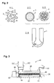
- a preferred heating-element material powder is such that secondary particles are not formed, and particles of a conductive ceramic 3 and particles of an insulating ceramic 5 are uniformly dispersed.
- the above-described method of the present invention attempts to dry a slurry that uses water as a solvent, through a dynamic process such as a fluidized-bed process, a rotary process, or a vibratory process in which powder is maintained in a fluidized state at all times. Further, the method attempts to dry the slurry that is placed in a container together with a medium. The slurry, together with a medium, is maintained in a fluidized state and dispersed while adhering to the surfaces of the medium. Since the dispersed slurry efficiently comes into contact with the air, the slurry is dried in a short period of time as a result of water being evaporated.
- Solid matter remaining on the surfaces of the medium exfoliates from the surfaces as a result of mutual friction and collision of the medium means.
- solid matter dispersed in the slurry i.e., conductive ceramic particles, insulating ceramic particles, and sintering aid particles
- these processes do not involve a step of pulverizing dry cakes, thereby providing good productivity.
- the insulating ceramic powder may comprise Si 3 N 4 .
- the conductive ceramic powder may comprise a material selected from the group consisting of TiN, MoSi 2 , WSi 2 , and WC.
- the density ratio between the conductive component and the insulating component assumes a large value of 1.7 to 4.9.
- the stationary drying process is not suitable for drying a water-solvent slurry having increased tendency toward aggregation of powder, since the process encounters difficulty in mitigating segregation ⁇ induced by difference in specific gravity ⁇ for reestablishing uniform dispersion even though crushing follows drying. That is, such a water-solvent slurry must be dried while being fluidized at all times.
- the phrase "predominantly contains water” means that a predominant amount of water in terms of % by mass is contained therein. That is, in some cases, a mixed solvent of water and a hydrophilic organic solvent such as an alcohol may be used. Needless to say, the powders and slurry contain unavoidable impurities; herein, only substantial components are referred to.
- Fig. 1 The method for manufacturing a ceramic heater according to the invention is schematically shown in Fig. 1, except for the drying step. The steps of the method will next be specifically described with reference to Fig. 1.
- a slurry 10 is obtained by suspending a conductive ceramic powder 3, an insulating ceramic powder 5, and a sintering aid powder 7 in ion-exchange treated water 9.
- the insulating ceramic powder is formed of Si 3 N 4
- the conductive ceramic powder 3 comprises a material selected from the group consisting of TiN, MoSi 2 , WSi 2 , and WC.
- the powders are individually purified and pulverized in advance. However, in preparation of the slurry 10, the powders may undergo micro-pulverization by use of a ball mill or an attritor.
- the powder when the conductive ceramic powder 3 of WC is to be used, the powder is preferably prepared such that the 50% particle size is about 1 ⁇ m as determined by use of a laser diffractometric particle-size analyzer.
- the powder when the insulating ceramic powder 5 formed of Si 3 N 4 is to be used, the powder preferably has a 50% particle size of about 1 ⁇ m.
- a sintering aid comprises a predominant amount of a rare earth oxide, and an oxide of at least one element selected from the elements belonging to Groups 3A, 4A, 5A, 3B (e.g., Al), and 4B (e.g., Si) in the periodic table.
- the sintering aid is added in an amount of 3% to 15% by mass.
- the sintering aid content is less than 3% by mass, a dense sintered body is difficult to obtain, whereas when the sintering aid content is in excess of 15% by mass, strength, toughness, or heat resistance may be insufficient.
- the sintering aid content is preferably 5% to 10% by mass.
- the 50% particle size of the sintering aid powder 7 is preferably adjusted in advance to about 5 ⁇ m.
- the conductive ceramic powder 3 (15 to 40 parts by mass), the insulating ceramic powder 5 (20 to 50 parts by mass), the sintering aid powder 7 (1 to 5 parts by mass), and the ion-exchange treated water 9 (25 to 50 parts by mass) are weighed and mixed by use of a stirring pot 16, thereby yielding the slurry 10.
- a rotary drying apparatus or vibratory drying apparatus which will be described later, is used for drying the slurry 10
- the above-mentioned material powders and water can be charged directly into the drying apparatus.
- the slurry 10 must be prepared separately, since the drying apparatus cannot prepare the slurry 10 directly from the powders and water.
- a general deflocculant is preferably not used, for when Na or a similar component is migrated into a material powder, a low-melting-point glass phase is generated, thereby impairing high-temperature durability of a ceramic heater.
- FIG. 3 schematically shows a vibratory drying apparatus 40.
- the vibratory drying apparatus 40 is configured such that a hollow container 43 is supported by springs 41, and vibration generated by a vibrator 42 is transmitted to the container 43 via a rod 44 joined to the container 43.
- a medium 22 is placed in the container 43 in an amount of about 10% to about 80% the volume of the container 43.
- the slurry 10 prepared separately in advance is charged into the vibratory drying apparatus 40.
- this vibratory drying apparatus 40 and a rotary drying apparatus 70 which will be described later, allow the material powders 3, 5, and 7 and water 9 to be charged directly therein.
- the powders are suspended in a sufficiently mixed condition through application of vibration or rotation, and drying can be started without stopping the apparatus.
- This method can eliminate labor associated with preparation and transport of the slurry 10 and thus can be expected to enhance productivity.
- continuous drying of the slurry 10 without interruption is difficult to attain.
- Hot gas HG is introduced into the container 43 so as to be brought into contact with the sufficiently suspended slurry 10.
- the slurry 10 is dispersed sufficiently by means of the violently vibrating medium 22 and assumes the form of a thin film on surfaces of the medium means 22 while water rapidly evaporates. Water contained in the slurry 10 flies off with outflow gas OG.
- An impacting action associated with mutual collision of the medium means suppresses the generation of secondary particles, thereby yielding a heating-element material powder 24 in the form of sufficiently mixed primary particles of the material powders.
- the container 43 may assume a dual structure such that an inner container can be closed and heated indirectly by means of a heating medium flowing through a space between the inner container and an outer container, thereby enabling heating under reduced pressure.
- the heating-element material powder 24 is collected from an outlet 46.
- the present embodiment employs a batch-processing apparatus. However, a continuous-processing apparatus to which the slurry 10 is continually fed can be employed instead. This also applies to the methods to be described below.
- the temperature of hot gas HG is set so as to fall within such an appropriate range of, for example 100°C-200°C, that the slurry 10 is sufficiently dried and that the obtained material powder is free from any problem such as thermal degradation.
- a hot gas temperature lower than 100°C is insufficient for drying the slurry 10; as a result, the obtained heating-element material powder 24 has an excessively high water content and thus tends to suffer aggregation.
- This temperature condition for hot gas HG is also applied to other drying methods to be described later.
- the container of the slurry 10 may be heated by use of an infrared heater or the like.
- the medium 22 substantially contributes to dispersion and drying of the slurry 10 and pulverization of powder, and assumes the form of balls of ceramic such as alumina, silicon nitride, or zirconia, or steel balls coated with urethane resin or epoxy resin. Since a typical drying apparatus uses a container body of stainless steel, use of resin-coated steel balls is preferred so as to reduce, to the greatest possible extent, migration of metallic impurities into a material powder. Incorporation of resin into the material powder is unlikely to raise problem, since the resin is eliminated during firing.
- the medium 22 is not necessarily in the form of balls and may assume, as appropriate, the form of a cube, a tubular form, or a plate-like form.
- the medium 22 for use in the vibratory drying apparatus 40 or the rotary drying apparatus 70 comprises resin-coated steel balls having a diameter of, for example, about 25 mm.
- the container of the drying apparatus is more preferably lined with urethane resin or the like.
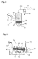
- Fig. 4 schematically shows a fluidized-bed drying apparatus 50.
- the apparatus 50 includes a vertically arranged tubular container 54.
- a hot gas HG inlet 55 is provided at a lower portion of the container 54.
- a medium holder 47 is provided within the container 54.
- the medium holder 47 is formed of a gas-passing element such as mesh or a plate having through-holes formed therein, and adapted to permit passage of hot gas HG, but not to permit passage of the medium 22.
- the medium 22 is placed in layers on the medium holder 47.
- Hot gas HG flows upward from underneath the medium holder 47 through the container 54 while agitating the medium 22.
- the slurry 10 is fed through a nozzle 51 in such a manner as to fall to the medium 22 from above.
- the slurry 10 is dried by means of hot gas HG, and a material powder adheres to the surfaces of the medium 22.
- the flow of hot gas HG causes repeated agitation and fall of the medium 22.
- the medium means 22 collide and rub against one another, thereby suppressing aggregation of powder particles.
- Material powder particles not greater than a predetermined particle size fly off with hot gas HG and are collected by means of a cyclone 52 and a bag filter 53.
- the medium 22 for use in the fluidized-bed drying apparatus 50 is adjusted to such weight and size as to be sufficiently agitated when hot gas HG flows therethrough and to be able to impart sufficiently large impact to material powder particles.
- the medium means are substantially uniform in size so as to leave an appropriate space thereamong, whereby the motion of the medium means is accelerated during flow of hot gas.
- Fig. 5 schematically shows the rotary drying apparatus 70.
- the rotary drying apparatus 70 includes an elongated tubular container 68 supported in such a manner as to have a rotation axis O inclined slightly with respect to the horizontal.
- the container 68 is rotationally driven by means of a motor 72 via a gear ring 71.
- Hot gas HG flows into the container 68 from one end with respect to the direction of the rotation axis O.
- the slurry 10 is charged into the container 68 from above the one end of the container 68 .
- the rotary drying apparatus 70 employs a parallel flow system; i.e., the inlet of the slurry 10 and the inlet of hot gas HG are located on the same side, so that the slurry 10 and hot gas HG move in the same direction.
- the rotary drying apparatus 70 may employ a counter flow system; i.e., the slurry 10 and hot gas HG move in opposite directions.
- the slurry 10 moves downstream through the container 68 while being dispersed to the medium 22 which is being agitated through rotary motion of the container 68, whereby evaporation of water is accelerated.
- the heating-element material powder 24 generated as a result of the slurry 10 being dried is collected in a collector 73 located at the downstream end of the container 68.
- the heating-element material powder contained in outflow gas OG is completely collected by means of a cyclone and/or bag filter.
- the heating-element material powder 24 is obtained by means of drying the slurry 10 by use of any drying apparatus described above. As shown in Fig. 1, the thus-obtained heating-element material powder 24 and a binder 26 are kneaded, and the resultant mixture is injected into a mold 29 by means of an injection molding unit 25 (1-4).
- the present method does not require a pulverization step, which is involved in the stationary drying method.
- a green resistance-heating element 28 is removed from the mold 29 and embedded in a separately prepared green ceramic substrate 30.
- the present embodiment employs silicon nitride ceramic as insulating ceramic used to form the ceramic substrate 30.
- Silicon nitride ceramic assumes a micro-structure such that main-phase grains predominantly formed of silicon nitride (Si 3 N 4 ) are bonded via a grain boundary phase derived from the previously mentioned sintering aid component or the like.
- the main phase may be such that a portion of Si or N atoms are substituted by A1 or O atoms, and may contain metallic atoms such as Y in the form of solid solution.
- Silicon nitride ceramic may contain the previously mentioned sintering aid component in an amount similar to that mentioned previously.
- the assembly of the resistance-heating element 28 and the ceramic substrate 30 is fired through a method such as HIP, thereby yielding a ceramic heater 1.
- a WC powder (5 vol.%; average particle size: 1 ⁇ m), an Si 3 N 4 powder (19 vol.%; average particle size: 1 ⁇ m), an Er 2 O 3 powder (0.8 vol.%; average particle size: 5 ⁇ m), an SiO 2 powder (0.2 vol.%; average particle size: 5 ⁇ m), and ion-exchange treated water (75 vol.%) were placed in a stirring pot 16 and stirred for suspension, thereby yielding a slurry 10.
- This slurry 10 was dried by the following two methods so as to obtain heating-element material powders 24: (1) stationary drying + dry crushing (ball mill); and (2) vibratory drying (medium employed).
- Each of the heating-element material powders 24 obtained by drying methods (1) and (2) was mixed with a binder.
- Each of the resultant mixtures was injection-molded into green resistance-heating elements 28.
- the green resistance-heating elements 28 were embedded in corresponding silicon nitride ceramic substrates 30.
- the resultant assemblies were fired, thereby yielding ceramic heaters 1.
- the thus-obtained ceramic heaters 1 were tested for repetitive-electricity-application durability. Specifically, a predetermined voltage was applied to each of the ceramic heaters 1 for one minute, and then the ceramic heater 1 was allowed to cool at room temperature for 30 seconds, which was taken as one cycle. The cycle was repeated until a disconnection fault occurred. The number of cycles as counted until occurrence of a disconnection fault was recorded as a durable limit. Voltage to be applied was set such that heater temperature reached 1,300°C, 1,350°C, 1,400°C, or 1,450°C at the first cycle. The repetitive-electricity-application durability test was carried out on five samples for each of the temperatures. The test results are shown in Tables 1 and 2.
- Table 1 (Comparative Example) shows the test results of drying method (1)
- Table 2 (Example) shows the test results of drying method (2).
- the ceramic heaters 1 were manufactured according to the same methods as those of Example 1.
- the 3-point bending test was carried out on samples classified according to employed conductive components and drying methods.
- flexural strength was measured at a regular-diameter portion adjacent to a rounded portion of a frontal end of the ceramic heater 1 under the following conditions: span 12 mm; and cross head speed 0.5 mm/sec.
- the regular-diameter portion of the ceramic heater has a diameter of 3.5 mm.
- Table 3 shows the test results of drying method (1)
- Table 4 shows the test results of drying method (2).
- manufacturing that employed the drying method of the present embodiment hardly yielded the ceramic heaters 1 having low strength, but consistently yielded the ceramic heaters 1 having high strength (specifically, not less than 1000 MPa in terms of 3-point flexural strength).
- a ceramic heater for use in a glow plug which is exposed to severe environment, or the interior of a combustion chamber of an engine, must have a 3-point flexural strength not less than 1000 MPa. Therefore, when the slurry 10 uses water as solvent, a method as described herein according to the invention must be used for drying the slurry 10, in preparation of the heating-element material powder 24.
Landscapes
- Engineering & Computer Science (AREA)
- Manufacturing & Machinery (AREA)
- Microelectronics & Electronic Packaging (AREA)
- Chemical & Material Sciences (AREA)
- Inorganic Chemistry (AREA)
- Resistance Heating (AREA)
- Compositions Of Oxide Ceramics (AREA)
Abstract
Description
characterized in that the solvent predominantly contains water and said drying of the slurry is performed by use of an apparatus selected from among a fluidized-bed drying apparatus, a rotary drying apparatus, and a vibratory drying apparatus, said apparatus being employed in combination with a medium.
| Temperature (°C) | 1300 | 1350 | 1400 | 1450 |
| 85296 | 24513 | 4210 | 84 | |
| 72100 | 15403 | 6598 | 120 | |
| 100000 | 9871 | 3947 | 251 | |
| 69987 | 21971 | 3681 | 421 | |
| 66142 | 18713 | 5228 | 214 | |
| Average (cycles) | 78705 | 18094 | 4733 | 218 |
| Temperature (°C) | 1300 | 1350 | 1400 | 1450 |
| 100000 | 100000 | 51093 | 387 | |
| 100000 | 91450 | 30650 | 274 | |
| 100000 | 100000 | 37678 | 547 | |
| 100000 | 100000 | 38754 | 421 | |
| 100000 | 100000 | 49826 | 394 | |
| Average (cycles) | 100000 | 98290 | 41600 | 405 |
| TiN | MoSi2 | WSi2 | WC | |
| 1152 | 1326 | 1045 | 667 | |
| 1222 | 1264 | 782 | 1087 | |
| 1315 | 889 | 957 | 941 | |
| 1088 | 1273 | 1069 | 889 | |
| 1297 | 1199 | 1187 | 1178 | |
| 1291 | 1144 | 1244 | 909 | |
| 1173 | 1304 | 882 | 1143 | |
| 1385 | 1057 | 1294 | 768 | |
| 1053 | 1100 | 1144 | 1188 | |
| 1331 | 1255 | 1029 | 1120 | |
| 1287 | 1163 | 732 | 956 | |
| 1190 | 1021 | 990 | 821 | |
| 1077 | 997 | 1209 | 1088 | |
| 1322 | 1105 | 1100 | 1045 | |
| 1244 | 1223 | 1033 | 921 | |
| 1106 | 923 | 1033 | 730 | |
| 1170 | 1058 | 932 | 898 | |
| 1299 | 1031 | 866 | 1055 | |
| 1078 | 981 | 1021 | 1029 | |
| 1229 | 933 | 1121 | 974 | |
| Average (MPa) | 1215 | 1112 | 1034 | 970 |
| TiN | MoSi2 | WSi2 | WC | |
| 1442 | 1420 | 1358 | 1181 | |
| 1357 | 1389 | 1432 | 1345 | |
| 1339 | 1408 | 1339 | 1277 | |
| 1412 | 1298 | 1420 | 1302 | |
| 1433 | 1310 | 1287 | 1149 | |
| 1279 | 1387 | 1266 | 1409 | |
| 1395 | 1423 | 1309 | 1246 | |
| 1262 | 1433 | 1359 | 1341 | |
| 1369 | 1254 | 1220 | 1340 | |
| 1423 | 1365 | 1385 | 1220 | |
| 1371 | 1369 | 1360 | 1369 | |
| 1322 | 1293 | 1399 | 1408 | |
| 1272 | 1320 | 1179 | 1388 | |
| 1240 | 1430 | 1336 | 1293 | |
| 1423 | 1229 | 1288 | 1343 | |
| 1389 | 1377 | 1248 | 1361 | |
| 1337 | 1349 | 1309 | 1299 | |
| 1357 | 1358 | 1377 | 1371 | |
| 1270 | 1421 | 1409 | 1420 | |
| 1341 | 1436 | 1458 | 1290 | |
| Average (MPa) | 1352 | 1363 | 1337 | 1318 |
Claims (13)
- A method for manufacturing a ceramic heater (1) comprising the steps of:wherein said solvent (9) predominantly contains water and said drying of said slurry (10) is performed by use of an apparatus selected from the group consisting of a fluidized-bed drying apparatus (50), a rotary drying apparatus (70), and a vibratory drying apparatus (40); and wherein said apparatus is employed in combination with a medium (22) in said drying step.mixing a conductive ceramic powder (3), an insulating ceramic powder (5), a sintering aid powder (7), and a solvent (9) so as to obtain a slurry (10);drying said slurry (10) so as to obtain a heating-element material powder (24);forming a resistance-heating element (28) from said heating-element material powder (24);embedding said resistance-heating element (28) in a ceramic substrate (30); andfiring a resultant assembly,
- A method according to claim 1, wherein said insulating ceramic powder (5) comprises Si3N4, and said conductive ceramic powder (3) comprises a material selected from the group consisting of TiN, MoSi2, WSi2, and WC.
- A method according to claim 1or 2, wherein said medium (22) comprises a plurality of solid objects.
- A method according to claim 1, 2 or 3, wherein said medium (22) comprises a medium for pulverization.
- A method according to any one of the preceding claims, wherein said medium (22) comprises a plurality of objects selected from the group consisting of ceramics, resins and resin-coated objects.
- A method according to any one of the preceding claims, wherein said medium (22) comprises a plurality of objects in the form of at least one of balls, cubes, tubes and/or plate-like shapes.
- A method according to any one of the preceding claims, wherein said drying step comprises using a hot gas at a temperature in the range of from 100°C to 200°C.
- A method according to any one of the preceding claims, which includes the step of dispersing the slurry on the surface of the medium (22).
- A method according to any one of the preceding claims, which includes the step of exfoliating dried powder from the surface of the medium (22).
- A method according to any one of the preceding claims, wherein the conductive ceramic powder (3), insulating powder (5) and sintering aid powder (7) are dispersed in ion-exchange treated water (9) to form the slurry (10).
- A method according to any one of the preceding claims, wherein the conductive ceramic powder (3) and insulating powder (5) each has an average particle size of approximately 1 µm.
- A method according to any one of the preceding claims, wherein the sintering aid powder (7) has an average particle size of approximately 5 µm.
- A method for manufacturing a glow plug for a diesel engine comprising manufacturing a ceramic heater according to any one of the preceding claims.
Applications Claiming Priority (2)
| Application Number | Priority Date | Filing Date | Title |
|---|---|---|---|
| JP2002051367A JP3984074B2 (en) | 2002-02-27 | 2002-02-27 | Manufacturing method of ceramic heater |
| JP2002051367 | 2002-02-27 |
Publications (3)
| Publication Number | Publication Date |
|---|---|
| EP1341400A2 true EP1341400A2 (en) | 2003-09-03 |
| EP1341400A3 EP1341400A3 (en) | 2006-06-28 |
| EP1341400B1 EP1341400B1 (en) | 2008-08-20 |
Family
ID=27678512
Family Applications (1)
| Application Number | Title | Priority Date | Filing Date |
|---|---|---|---|
| EP03251168A Expired - Lifetime EP1341400B1 (en) | 2002-02-27 | 2003-02-26 | Method for manufacturing ceramic heater |
Country Status (4)
| Country | Link |
|---|---|
| US (1) | US7347966B2 (en) |
| EP (1) | EP1341400B1 (en) |
| JP (1) | JP3984074B2 (en) |
| DE (1) | DE60322992D1 (en) |
Families Citing this family (4)
| Publication number | Priority date | Publication date | Assignee | Title |
|---|---|---|---|---|
| JP5844621B2 (en) * | 2011-11-15 | 2016-01-20 | 日本特殊陶業株式会社 | Method for manufacturing ceramic heater, method for manufacturing glow plug, ceramic heater and glow plug |
| JP5837400B2 (en) * | 2011-11-15 | 2015-12-24 | 日本特殊陶業株式会社 | Method for manufacturing ceramic heater and method for manufacturing glow plug |
| JP5837401B2 (en) * | 2011-11-15 | 2015-12-24 | 日本特殊陶業株式会社 | Method for manufacturing ceramic heater and method for manufacturing glow plug |
| CN106089542B (en) * | 2016-07-28 | 2018-05-29 | 安徽精鑫汽车电子电器有限公司 | A kind of glow plug shakes powder platform |
Family Cites Families (8)
| Publication number | Priority date | Publication date | Assignee | Title |
|---|---|---|---|---|
| JP2804393B2 (en) * | 1991-07-31 | 1998-09-24 | 京セラ株式会社 | Ceramic heater |
| JPH0812462A (en) | 1994-06-22 | 1996-01-16 | Denki Kagaku Kogyo Kk | Electroconductive ceramic, its production and use |
| JP3411498B2 (en) * | 1997-04-23 | 2003-06-03 | 日本特殊陶業株式会社 | Ceramic heater, method of manufacturing the same, and ceramic glow plug |
| US5993722A (en) * | 1997-06-25 | 1999-11-30 | Le-Mark International Ltd. | Method for making ceramic heater having reduced internal stress |
| US6274855B1 (en) * | 1998-11-17 | 2001-08-14 | Ngk Spark Plug Co., Ltd. | Heating resistor for ceramic heaters, ceramic heaters and method of manufacturing ceramic heaters |
| US6084212A (en) * | 1999-06-16 | 2000-07-04 | Le-Mark International Ltd | Multi-layer ceramic heater element and method of making same |
| JP3889536B2 (en) * | 1999-10-29 | 2007-03-07 | 日本特殊陶業株式会社 | Ceramic heater, method for manufacturing the same, and glow plug including the ceramic heater |
| JP4454191B2 (en) * | 2001-07-30 | 2010-04-21 | 日本特殊陶業株式会社 | Manufacturing method of ceramic heater |
-
2002
- 2002-02-27 JP JP2002051367A patent/JP3984074B2/en not_active Expired - Fee Related
-
2003
- 2003-02-25 US US10/372,134 patent/US7347966B2/en not_active Expired - Fee Related
- 2003-02-26 EP EP03251168A patent/EP1341400B1/en not_active Expired - Lifetime
- 2003-02-26 DE DE60322992T patent/DE60322992D1/en not_active Expired - Lifetime
Also Published As
| Publication number | Publication date |
|---|---|
| JP2003257594A (en) | 2003-09-12 |
| EP1341400A3 (en) | 2006-06-28 |
| US20030183990A1 (en) | 2003-10-02 |
| EP1341400B1 (en) | 2008-08-20 |
| JP3984074B2 (en) | 2007-09-26 |
| DE60322992D1 (en) | 2008-10-02 |
| US7347966B2 (en) | 2008-03-25 |
Similar Documents
| Publication | Publication Date | Title |
|---|---|---|
| JP3821730B2 (en) | Manufacturing method of tungsten-copper composite powder and manufacturing method of sintered alloy for heat sink using the same | |
| KR930009895B1 (en) | Boron carbide aluminium and boron carbide reactive metal cermets | |
| EP0353860A2 (en) | Expanded mineral particles and apparatus and method of production | |
| EP1341400B1 (en) | Method for manufacturing ceramic heater | |
| JP2013147368A (en) | Ceramic cylindrical sputtering target material and manufacturing method thereof | |
| US6464906B1 (en) | Method of manufacturing spherical bodies by rotation, spherical bodies made by the method and a powder composition for use in the method | |
| EP1160222A2 (en) | Manufacturing method of ceramic matrix composite | |
| KR20160138612A (en) | Method for Manufacturing Ceramic Spherical Bead | |
| CN101365661B (en) | Method for producing carbon-containing silicon carbide ceramic | |
| Kićević et al. | A statistical analysis of the influence of processing conditions on the properties of fused silica | |
| KR100621666B1 (en) | High temperature wear resistant low friction coating powder and its manufacturing method | |
| CN115368144B (en) | Piezoelectric ceramic ultrafine powder, preparation method and piezoelectric ceramic membrane | |
| JP3508178B2 (en) | Manufacturing method of ceramic fine powder material | |
| JP3807235B2 (en) | Discharge resistant composite material and manufacturing method thereof | |
| JP3486108B2 (en) | Power resistor, method of manufacturing the same, and power resistor | |
| JP3748084B2 (en) | Method for producing NiO / YSZ composite powder | |
| JPH0753272A (en) | Coated ceramic quasi-fine particles, ceramic-based sintered body and method for producing the same | |
| JPS6030248B2 (en) | Granulation method of ceramic raw material powder | |
| CN120945311B (en) | Partially Yttrium Stabilized Zirconia Powder with Multimorphic Porous Structure and Its Preparation Method | |
| JPH07100403A (en) | Fine powder manufacturing method and manufacturing apparatus | |
| KR102533253B1 (en) | Method for manufacturing ceramic body | |
| CN120025172A (en) | A micron-sized spherical boron carbide ceramic and a preparation method thereof | |
| JP2002128570A (en) | Manufacturing method and manufacturing apparatus for granules for ceramic molding, granules for molding, molded bodies and sintered bodies | |
| Miclea et al. | Advanced technology for making PZT type ceramics by fast firing | |
| EP0974984B1 (en) | Manufacture of varistors |
Legal Events
| Date | Code | Title | Description |
|---|---|---|---|
| PUAI | Public reference made under article 153(3) epc to a published international application that has entered the european phase |
Free format text: ORIGINAL CODE: 0009012 |
|
| AK | Designated contracting states |
Kind code of ref document: A2 Designated state(s): AT BE BG CH CY CZ DE DK EE ES FI FR GB GR HU IE IT LI LU MC NL PT SE SI SK TR |
|
| AX | Request for extension of the european patent |
Extension state: AL LT LV MK RO |
|
| PUAL | Search report despatched |
Free format text: ORIGINAL CODE: 0009013 |
|
| AK | Designated contracting states |
Kind code of ref document: A3 Designated state(s): AT BE BG CH CY CZ DE DK EE ES FI FR GB GR HU IE IT LI LU MC NL PT SE SI SK TR |
|
| AX | Request for extension of the european patent |
Extension state: AL LT LV MK RO |
|
| 17P | Request for examination filed |
Effective date: 20060906 |
|
| AKX | Designation fees paid |
Designated state(s): DE FR |
|
| 17Q | First examination report despatched |
Effective date: 20070207 |
|
| GRAP | Despatch of communication of intention to grant a patent |
Free format text: ORIGINAL CODE: EPIDOSNIGR1 |
|
| GRAS | Grant fee paid |
Free format text: ORIGINAL CODE: EPIDOSNIGR3 |
|
| GRAA | (expected) grant |
Free format text: ORIGINAL CODE: 0009210 |
|
| AK | Designated contracting states |
Kind code of ref document: B1 Designated state(s): DE FR |
|
| REF | Corresponds to: |
Ref document number: 60322992 Country of ref document: DE Date of ref document: 20081002 Kind code of ref document: P |
|
| PLBE | No opposition filed within time limit |
Free format text: ORIGINAL CODE: 0009261 |
|
| STAA | Information on the status of an ep patent application or granted ep patent |
Free format text: STATUS: NO OPPOSITION FILED WITHIN TIME LIMIT |
|
| 26N | No opposition filed |
Effective date: 20090525 |
|
| REG | Reference to a national code |
Ref country code: FR Ref legal event code: PLFP Year of fee payment: 13 |
|
| PGFP | Annual fee paid to national office [announced via postgrant information from national office to epo] |
Ref country code: DE Payment date: 20150218 Year of fee payment: 13 |
|
| PGFP | Annual fee paid to national office [announced via postgrant information from national office to epo] |
Ref country code: FR Payment date: 20150210 Year of fee payment: 13 |
|
| REG | Reference to a national code |
Ref country code: DE Ref legal event code: R119 Ref document number: 60322992 Country of ref document: DE |
|
| REG | Reference to a national code |
Ref country code: FR Ref legal event code: ST Effective date: 20161028 |
|
| PG25 | Lapsed in a contracting state [announced via postgrant information from national office to epo] |
Ref country code: DE Free format text: LAPSE BECAUSE OF NON-PAYMENT OF DUE FEES Effective date: 20160901 Ref country code: FR Free format text: LAPSE BECAUSE OF NON-PAYMENT OF DUE FEES Effective date: 20160229 |