EP1341361A2 - Vorrichtung zur Anbringung eines elektronischen Gerätes an einem Träger - Google Patents
Vorrichtung zur Anbringung eines elektronischen Gerätes an einem Träger Download PDFInfo
- Publication number
- EP1341361A2 EP1341361A2 EP03003438A EP03003438A EP1341361A2 EP 1341361 A2 EP1341361 A2 EP 1341361A2 EP 03003438 A EP03003438 A EP 03003438A EP 03003438 A EP03003438 A EP 03003438A EP 1341361 A2 EP1341361 A2 EP 1341361A2
- Authority
- EP
- European Patent Office
- Prior art keywords
- carrier
- electronic device
- fixed
- magnetic
- electronic
- Prior art date
- Legal status (The legal status is an assumption and is not a legal conclusion. Google has not performed a legal analysis and makes no representation as to the accuracy of the status listed.)
- Withdrawn
Links
Images

Classifications
-
- A—HUMAN NECESSITIES
- A45—HAND OR TRAVELLING ARTICLES
- A45F—TRAVELLING OR CAMP EQUIPMENT: SACKS OR PACKS CARRIED ON THE BODY
- A45F5/00—Holders or carriers for hand articles; Holders or carriers for use while travelling or camping
- A45F5/02—Fastening articles to the garment
-
- A—HUMAN NECESSITIES
- A45—HAND OR TRAVELLING ARTICLES
- A45F—TRAVELLING OR CAMP EQUIPMENT: SACKS OR PACKS CARRIED ON THE BODY
- A45F5/00—Holders or carriers for hand articles; Holders or carriers for use while travelling or camping
- A45F5/1508—Holders or carriers for portable audio devices, e.g. headphones or digital music players
Definitions
- the invention relates to a device for attaching a electronic device on a support, the device is fixed or fixable on the carrier.
- Such devices are known from the prior art.
- clamping devices are too mobile So-called "headsets" belonging to telecommunications terminals known.
- Headset generally from a with a lead to the Telecommunications terminal provided microphone and one earphones linked to the microphone via another line.
- One of these lines is generally fixed connected to the clamping device, which then, for example a garment can be clamped.
- the line lengths must be dimensioned so that the different Ways to attach the clamp to it each is possible, the earphone to the ear, or the microphone in one position suitable for sound recording.
- Telecommunications terminal is not used and there are earphones or microphone not in a suitable for making calls Position, based on the above Hang the wire sizing down on the user. This can disturb the wearer during movements and make reuse difficult of the headset, since it has to be searched with difficulty got to. In addition, a down-registering on the person carrying it acts The headset is unattractive and will not work for this reason desired.
- a fastening device for a microphone which consists of a microphone holder and a needle holder Counterpart exists, and thus on a piece of clothing can be attached. It is attached with needles provided counterpart for example on the inside of the Garment pressed so that the needles through the Protrude through the garment.
- the microphone holder on which the microphone is attached has openings that lead to Picking up and locking the needles are suitable. The microphone holder is then opened with the appropriate openings from pressed on the outside of the needles and locked there.
- a disadvantage this device is that the garment is there damaged by the needles.
- Another disadvantage lies in that the microphone is not simply removed at short notice and can be reattached quickly because of the small dimensions bringing together needles and openings can take some time and generally visual contact requires.
- clamping devices for the above mentioned Headsets known for mobile telecommunications devices which is also used to attach the headset to a piece of clothing are suitable. These clamps are like this trained that the earphones directly in in the clamps inserted recesses can be clamped.
- these devices have compared to the above Clamping device has the advantage that the earphones Do not dangle from your body when not in use. They have however, the disadvantage that it may take some time and patience is needed to get the relatively small earphones after the Return use to the appropriate openings. in the In general, even visual contact is necessary, which is the case with the normal holder of the headset, for example, on one Shirt collar, a button placket or a jacket in general is difficult.
- the object is achieved by an attachment device of an electronic device on a carrier, the device is fixed or fixable on the carrier and wherein the electronic device attached to the device by magnetic Forces is fixable.
- the electronic device is inconspicuous held directly on the device and does not hang down, as in the known from the prior art and initially mentioned “clamping device” for attaching a "headset" on one person.
- the present invention therefore has the further advantage that with it you can fix an electronic device inconspicuously can.
- the device according to the invention can also, for example Be designed so that you can attach multiple electronic Equipment is suitable.
- the electronic device and the device can continue be designed so that one or both of the two Include permanent magnets.
- This has the advantage that none additional technical effort to generate the magnetic Forces must be driven, such as in the use of an electromagnet by provision a power source is required.
- the mentioned embodiment, where both the electronic device and the Device comprises a permanent magnet has the other Advantage that relatively large magnetic forces can be realized are. This allows an even more stable fixation of the electronic device on the device. It also increases the "radius of action" of the device. That means the maximum distance below which the electronic device is still attracted to the device becomes, grows, and thus further simplifies handling becomes.
- the electronic device or device at least partially made of ferromagnetic material for interaction formed with the permanent magnet of the other component is. This means that one of the components - electronic Device or device - the use of a permanent magnet be avoided, which can lead to weight savings can. This can be especially true with small and light electronic Devices or devices, such as "headsets", be an advantage.
- the electronic Device When removing the electronic device from the device it may be desirable or necessary for the electronic Device a predetermined orientation with respect to the Device. For example, with known spatial removal of the device easier. equally is conceivable that a certain spatial orientation for the correct functioning of the device in the fixed Condition is necessary. In this context, must be guaranteed be a fixation of the electronic Device on the device always in the same way happens. This can be achieved, for example, that the surface of the device at least in sections is provided with a profile, which to interact with a complementary profiling of the electronic Device is trained. That means the surface the device, for example, one of the electronic form Device has corresponding recess, in which the electronic device through the magnetic forces is "drawn in", essentially independently, into what position the user is near the device brings.
- the device can hold mechanical Include fixation of the electronic device.
- the profile of at least a portion of the device be designed as a mechanical holding means.
- the mechanical Holding means guarantee in cooperation with the magnetic forces a stable fixation of the electronic Device even under heavy loads.
- the device itself by means of magnetic forces can be fixed on a carrier. Thereby the device can be easily attached to the carrier and also lose weight again.
- the device can be a permanent magnet include, with which the device on a ferromagnetic Carrier or on a permanent magnet or Carrier comprising electromagnets can be attached.
- a variety of ferromagnetic metallic objects Possess properties offers such a trained Device an easy way to get an electronic Device using the device on a variety of metallic Carriers, such as magnetic blackboards, to attach metallic cabinet doors, radiators and the like.
- the invention provide that the device two elements that can be fixed relative to one another by magnetic forces comprises, the carrier in the fixed state of the two magnetic elements at least in sections between this extends.
- the carrier becomes more or less between the elements "jammed” the device, causing the device can no longer move relative to the carrier.
- the device can have two separate devices Elements are formed, which are located opposite each other Sides of the carrier.
- the Device in the manner of a clip formed in one piece be, the magnetic forces relative to each other fixable elements on two opposite, clamping Parts of the bracket can be attached.
- the carrier must be such that the magnetic force between the two magnetic elements despite possible weakening through the intermediate carrier material is sufficient to the Fix the device to the carrier.
- the two-element design the device according to the invention has the advantage that the carrier is not damaged and the fixation of the Device essentially of the material and the material consistency (e.g. flexibility, hardness, strength, brittleness) of the wearer is independent.
- the Device is mechanically fixed to a support. This is particularly advantageous if a permanent connection the device with the carrier is desired.
- the mechanical Means for attaching the device the carrier can be used, for example Screws, clamps, clamps, hooks, sewing thread, cord, glue, Velcro fastener, buttons, cufflinks, tie pins or any combination of these.
- Another advantageous embodiment of the present Invention consists in a device for attaching the electronic device on the carrier, being electronic Device and device are formed in one piece, and wherein continue the device by means of magnetic forces Carrier is fixable.
- This integration of electronic Device with the device offers a particularly handy and flexible way, for example the electronic device on ferromagnetic materials, such as magnetic walls, metallic Doors, metallic walls, etc., or on magnets too fix.
- the advantage of this embodiment is that that one can attach the electronic device to the carrier no separate component is required as this is in the electronic Device is already integrated. This brings advantages Embodiment especially for electronic devices, which are transportable or intended for mobile use are.
- Devices can, for example, devices for data acquisition, Data forwarding or data playback, such as for example speakers, earphones, displays, stylus pens or microphones, or also connected with such devices electrical supply lines, plugs, controls (e.g. on-off switch, call acceptance button, volume control) or switch.
- These devices for data acquisition or data playback for example, with electronic Data processing systems, personal computers, laptops, Palmtops, organizers or telecommunication devices be connected. Since the devices for data acquisition, Data transmission and data playback are naturally nearby of the user, but only at the time of for example, data acquisition or data playback the device according to the invention is actually required suitable for attaching such devices to a Carrier.
- the device according to the invention is also advantageous for electronic devices that are part of a mobile telecommunications terminal as this is essentially from the user is always carried around for telecommunications messages to be reachable.
- electronic device for example a connecting line between a mobile phone and an associated headset, an earphone, a headphone, a display, a mini display, a microphone, a stylus, a control, a part a hearing device, an electroacoustic transducer or combinations of the aforementioned devices.
- Further preferred electronic devices can for example Solar panels or external batteries.
- suitable electronic devices generally by people carried and / or used are preferred carriers for example those which are flexible non-magnetic materials include.
- the carrier can in this connection Cover textile or leather or a garment his.
- the carrier can also be any solid, non-magnetic material such as wood, plastic or metal, a flexible non-magnetic material like fabric, Cloth, fabric, foil or combinations of firm and flexible be non-magnetic materials. Of course, too Combinations of these materials with magnetic materials suitable as carrier materials.
- the invention Device firmly connected to a garment of the user is.
- the device could be magnetic trained shirt button, or one in a shirt collar, a shirt pocket, a lapel or a jacket pocket sewn magnetic piece of material.
- Such devices are not from the outside as fasteners recognizable and fulfilled for an electronic device nevertheless all requirements for a device for attachment of an electronic device. It can also be beneficial be when the device according to the invention with the User is connected. Such devices could Examples are bracelets, necklaces or ear clips.
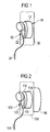
- Figure 1 shows an inventive device 10 for attachment an earphone 20 on a carrier 30 have the device 10 and the electronic device 20th magnetically effective areas 12, 22, which are mutually attract.
- the magnetic areas 12, 22 designed so that the magnetic forces in the fixed State are sufficiently large to the electronic device 20th in its normal usage environment and under the normal Terms of use essentially fixed to the device 10 to fix.
- the lead 24 to the earphone connects this for example with a mobile telecommunications terminal or a device for playing music like one Tape recorder, a Walkman, a CD player, or an MP3 player.
- the carrier 30 can be any solid or flexible material his.
- the device 10 can, for example, on this be glued or screwed on or by magnetic forces be held on this.
- the magnetically effective areas 12, 22 of the electronic device 20 and the device 10 can both comprise permanent magnetic components. alternative it is also possible that only one of the areas 12, 22 comprises a permanent magnetic component, and in each other area 12, 22 ferromagnetic material is available.
- the user can easily use the earphone 20 removed from the holder 10 and inserted into the ear. After the end of use, the earphone 20 becomes close brought the magnetically effective region 12 of the holder 10 and of the magnetic forces between the magnetic effective area 22 of the earphone and the magnetically effective Area 12 of the holder pulled towards this and there fixed.
- Figure 2 shows a holder 110 for attaching an earphone 120 on a fabric 130.
- the holder 110 is there two-element 114, 116 executed.
- the fabric 130 is between the elements 114, 116 of the holder 110.
- the first element 114 of the holder 110 has a first magnetically active one on one side Area 112 for fixing the earphone 120 and on the opposite side a not shown in Figure 2 second magnetic area for fixing the second element 116 of the carrier 110.
- the second element 116 of the holder 110 has on it the first element 114 of the holder 110 facing side also not shown in Figure 2 magnetically effective area for fixation with the first element 114.
- the earphone 120 also has one magnetically effective area 122 for fixing to the magnetic effective area 112 of the holder 110.
- the earphone 120 is via a line 124, for example with a mobile telecommunications terminal or a device for playing back Audio data, such as a radio, a cassette recorder, a Walkman a dictation machine, an MP3 player, a CD player or a control unit.
- the earphone 120 is operated as in the exemplary embodiment, which is shown in connection with Figure 1 has been.
- the holder 110 is attached to the fabric 130, by placing the first element 114 on one side of the fabric in the proximity of the second element 116 on the other side of the Material is brought and this by magnetic forces attract. This will make the fabric 130 between the elements 114, 116 of the holder 110 "clamped” and so the holder 110 attached to fabric 130.
- Figure 3 shows the holder of a headset 200, for example of a mobile telecommunication terminal on the body 300 of a user by means of two magnetic holders 250, 260.
- the microphone 220 of the headset 200 is on a magnet holder 260 fixed while the earphones 210 of the headset 200 is fixed to the other magnet holder 250.
- Microphone 220 and Earphones 210 are connected by line 230.
- the headset 200 total is through line 240 for example connected to the telecommunications terminal.
- the magnet holder 250, 260 can be on clothing, for example sewn by the user or by a two-element trained carrier to be clamped.
- earphones 210 can be magnetic Holder 250 and microphone 220 from the magnetic holder 260 can be removed. After the conversation is over brought the microphone 220 close to the magnet holder 260 and attracted to it and fixed to it. In the same Way, the earphone 210 is brought near the holder 250, attracted by this and also fixed there.
- the holder 260 for the microphone 220 so that it can be used to record the language of the User does not have to be removed.
- the advantage of this Embodiment is that to use the telecommunications device only the earphone 210 from its holder 250 removed and fixed there again after use must be what the effort of starting and ending a conversation with the telecommunication device is reduced.
- the present invention describes an apparatus for Attaching an electronic device to a carrier, the electronic device attached to the device by magnetic Forces can be fixed, as well as further preferred embodiments this device.
- the invention provides one easy-to-use, flexible option for attachment an electronic device on a carrier, which is also easily detachable and reconnectable and with which nevertheless achieves a sufficiently good fixation becomes.
Landscapes
- Telephone Set Structure (AREA)
- Casings For Electric Apparatus (AREA)
Abstract
Description
- Figur 1
- eine erfindungsgemäße Vorrichtung zur Befestigung eines Ohrhörers an einem Träger;
- Figur 2
- eine zweielementige Vorrichtung zur Befestigung eines Ohrhörers an einem Stoff; und
- Figur 3
- Vorrichtungen zur Befestigung der Komponenten eines Headsets an einer Person.
Claims (15)
- Vorrichtung (10; 110; 250, 260) zur Anbringung eines elektronischen Gerätes (20; 120; 210, 220) an einem Träger (30; 130; 300), wobei die Vorrichtung (10; 110; 250, 260) an dem Träger (30; 130; 300) fixiert oder fixierbar ist,
dadurch gekennzeichnet, dass das elektronische Gerät (20; 120; 210, 220) an der Vorrichtung (10; 110; 250, 260) durch magnetische Kräfte fixierbar ist. - Vorrichtung nach Anspruch 1,
dadurch gekennzeichnet, dass das elektronische Gerät (20; 120; 210, 220) und/oder die Vorrichtung (10; 110; 250, 260) einen Permanentmagneten umfassen. - Vorrichtung nach Anspruch 2,
dadurch gekennzeichnet, dass das elektronische Gerät (20; 120; 210, 220) oder die Vorrichtung (10; 110; 250, 260) zumindest teilweise aus ferromagnetischem Material zum Zusammenwirken mit dem Permanentmagneten ausgebildet ist. - Vorrichtung nach einem der Ansprüche 1 bis 3,
dadurch gekennzeichnet, dass die Oberfläche der Vorrichtung (10; 110; 250, 260) zumindest abschnittsweise mit einer Profilierung versehen ist, welche zum Zusammenwirken mit einer Komplementärprofilierung des elektronischen Geräts (20; 120; 210, 220) ausgebildet ist. - Vorrichtung nach einem der Ansprüche 1 bis 4,
dadurch gekennzeichnet, dass die Vorrichtung weiterhin Haltemittel zur mechanischen Fixierung des elektronischen Geräts umfasst. - Vorrichtung nach einem der Ansprüche 1 bis 5,
dadurch gekennzeichnet, dass die Vorrichtung (10; 110; 250, 260) mittels magnetischer Kräfte an dem Träger (30; 130; 300) fixierbar ist. - Vorrichtung nach einem der Ansprüche 1 bis 5,
dadurch gekennzeichnet, dass die Vorrichtung (10; 110; 250, 260) zwei durch magnetische Kräfte relativ zueinander fixierbare Elemente (114, 116) umfasst, wobei sich der Träger (30; 130; 300) im fixierten Zustand der zwei magnetischen Elemente (114, 116) zumindest abschnittsweise zwischen diesen erstreckt. - Vorrichtung nach Anspruch 7,
dadurch gekennzeichnet, dass im fixierten Zustand gegenüberliegende Flächen der zwei fixierbaren Elemente (114, 116) der Vorrichtung (10; 110; 250, 260) derart ausgebildet sind, dass sie im fixierten Zustand unter Berücksichtigung der Dicke des dazwischen befindlichen Bereichs des Trägers (30; 130; 300) im wesentlichen passgenau ineinander greifen. - Vorrichtung nach einem der Ansprüche 7 oder 8,
dadurch gekennzeichnet, dass mindestens eine der im fixierten Zustand einander gegenüberliegenden Flächen der zwei fixierbaren Elemente (114, 116) der Vorrichtung (10; 110; 250, 260) derart ausgebildet ist, dass sie im fixierten Zustand gegenüber dem Träger (30; 130; 300) eine erhöhte Haftreibung aufweist. - Vorrichtung nach einem der Ansprüche 1 bis 5,
dadurch gekennzeichnet, dass die Vorrichtung (10; 110; 250, 260) mechanisch am Träger (30; 130; 300) fixierbar ist. - Vorrichtung (10; 110; 250, 260) zur Anbringung eines elektronischen Gerätes (20; 120; 210, 220) an einem Träger (30; 130; 300),
dadurch gekennzeichnet, dass das elektronische Gerät (20; 120; 210, 220) und die Vorrichtung (10; 110; 250, 260) einteilig ausgebildet sind, und dass weiterhin die Vorrichtung (10; 110; 250, 260) mittels magnetischer Kräfte an dem Träger (30; 130; 300) fixierbar ist. - Vorrichtung nach einem der vorhergehenden Ansprüche,
dadurch gekennzeichnet, dass das elektronische Gerät (20; 120; 210, 220) als Vorrichtung zur Datenaufnahme, Datenweiterleitung oder Datenwiedergabe, wie beispielsweise ein Lautsprecher, Ohrhörer (210), Display, Eingabestift, Bedienelement, Zuleitung oder Mikrofon (220) ausgebildet ist. - Vorrichtung nach einem der vorhergehenden Ansprüche,
dadurch gekennzeichnet, dass das elektronische Gerät (20; 120; 210, 220) Teil eines mobilen Telekommunikationsendgerätes ist. - Vorrichtung nach einem der vorhergehenden Ansprüche,
dadurch gekennzeichnet, dass der Träger (30; 130; 300) flexibles, unmagnetisches Material umfasst. - Vorrichtung nach einem der vorhergehenden Ansprüche,
dadurch gekennzeichnet, dass der Träger (30; 130; 300) ein Textilstoff oder Leder ist.
Applications Claiming Priority (2)
| Application Number | Priority Date | Filing Date | Title |
|---|---|---|---|
| DE10209085 | 2002-03-01 | ||
| DE2002109085 DE10209085A1 (de) | 2002-03-01 | 2002-03-01 | Vorrichtung zur Anbringung eines elektronischen Gerätes an einem Träger |
Publications (2)
| Publication Number | Publication Date |
|---|---|
| EP1341361A2 true EP1341361A2 (de) | 2003-09-03 |
| EP1341361A3 EP1341361A3 (de) | 2010-04-14 |
Family
ID=27675156
Family Applications (1)
| Application Number | Title | Priority Date | Filing Date |
|---|---|---|---|
| EP03003438A Withdrawn EP1341361A3 (de) | 2002-03-01 | 2003-02-14 | Vorrichtung zur Anbringung eines elektronischen Gerätes an einem Träger |
Country Status (2)
| Country | Link |
|---|---|
| EP (1) | EP1341361A3 (de) |
| DE (1) | DE10209085A1 (de) |
Cited By (5)
| Publication number | Priority date | Publication date | Assignee | Title |
|---|---|---|---|---|
| WO2009047808A1 (en) * | 2007-10-12 | 2009-04-16 | Preggioni Ehf. | Cord adjustment device |
| EP2813744A1 (de) | 2013-06-14 | 2014-12-17 | Sennheiser Communications A/S | Steuerungsvorrichtung zur Anrufsteuerung |
| US9282393B2 (en) | 2004-07-06 | 2016-03-08 | Kaddan Entertainment, Inc. | System and method for securing headphone transducers |
| US9648407B2 (en) | 2014-06-12 | 2017-05-09 | Kaddan Entertainment, Inc. | System and method for managing headphone wires |
| AT519412A1 (de) * | 2016-11-28 | 2018-06-15 | Lb Acoustics Messgeraete Gmbh | Montagesystem für Kopfhörer |
Citations (1)
| Publication number | Priority date | Publication date | Assignee | Title |
|---|---|---|---|---|
| JP2001128275A (ja) | 1999-10-29 | 2001-05-11 | Matsushita Electric Ind Co Ltd | マイクロホン |
Family Cites Families (7)
| Publication number | Priority date | Publication date | Assignee | Title |
|---|---|---|---|---|
| BE633653A (de) * | 1962-06-19 | |||
| DE3127117A1 (de) * | 1981-07-09 | 1983-02-17 | Fedke oHG, 7317 Wendlingen | Halterung fuer arbeitsgeraetschaften |
| DE8903173U1 (de) * | 1989-03-15 | 1989-05-03 | Voit, Stefan, Dipl.-Wirtsch.-Ing., 66386 St Ingbert | Halterung für tragbare elektronische Geräte |
| DE19701890C1 (de) * | 1997-01-21 | 1998-10-22 | Voelk Maschinenbau Gmbh | Befestigungs-Vorrichtung für Servietten an Krawatten und dergleichen |
| JP2000189227A (ja) * | 1998-12-28 | 2000-07-11 | Kyoei Sangyo Kk | 携帯電話機用ホルダ― |
| DE19910692C2 (de) * | 1999-03-10 | 2001-03-01 | Testo Gmbh & Co | Elektronisches Gerät |
| US6260749B1 (en) * | 1999-10-15 | 2001-07-17 | Eitan Horovitz | Small article holder including magnet means |
-
2002
- 2002-03-01 DE DE2002109085 patent/DE10209085A1/de not_active Withdrawn
-
2003
- 2003-02-14 EP EP03003438A patent/EP1341361A3/de not_active Withdrawn
Patent Citations (1)
| Publication number | Priority date | Publication date | Assignee | Title |
|---|---|---|---|---|
| JP2001128275A (ja) | 1999-10-29 | 2001-05-11 | Matsushita Electric Ind Co Ltd | マイクロホン |
Cited By (10)
| Publication number | Priority date | Publication date | Assignee | Title |
|---|---|---|---|---|
| US9282393B2 (en) | 2004-07-06 | 2016-03-08 | Kaddan Entertainment, Inc. | System and method for securing headphone transducers |
| US9510080B2 (en) | 2004-07-06 | 2016-11-29 | Kaddan Entertainment, Inc. | System and method for securing headphone transducers |
| US9820031B2 (en) | 2004-07-06 | 2017-11-14 | Kaddan Entertainment, Inc. | System and method for securing headphone transducers |
| US10200777B2 (en) | 2004-07-06 | 2019-02-05 | Kaddan Entertainment, Inc. | System and method for securing headphone transducers |
| WO2009047808A1 (en) * | 2007-10-12 | 2009-04-16 | Preggioni Ehf. | Cord adjustment device |
| CN101822031A (zh) * | 2007-10-12 | 2010-09-01 | 普雷吉奥尼有限责任公司 | 绳线调节装置 |
| EP2813744A1 (de) | 2013-06-14 | 2014-12-17 | Sennheiser Communications A/S | Steuerungsvorrichtung zur Anrufsteuerung |
| US9648407B2 (en) | 2014-06-12 | 2017-05-09 | Kaddan Entertainment, Inc. | System and method for managing headphone wires |
| AT519412A1 (de) * | 2016-11-28 | 2018-06-15 | Lb Acoustics Messgeraete Gmbh | Montagesystem für Kopfhörer |
| AT519412B1 (de) * | 2016-11-28 | 2019-09-15 | Lb Acoustics Messgeraete Gmbh | Montagesystem für Kopfhörer |
Also Published As
| Publication number | Publication date |
|---|---|
| DE10209085A1 (de) | 2003-09-11 |
| EP1341361A3 (de) | 2010-04-14 |
Similar Documents
| Publication | Publication Date | Title |
|---|---|---|
| DE69413087T2 (de) | Kopfhörer | |
| DE10320863B3 (de) | Befestigung eines Hörhilfegerätes oder einer Otoplastik im Ohr | |
| DE102007055385B4 (de) | Abschirmungseinrichtung für ein Hörhilfegerät | |
| DE112018004007T5 (de) | Mikro-planarlautsprecher | |
| DE19747562C2 (de) | Verfahren und Anordnung zum Steuern der Ausbreitung von Magnetfeldern durch elektrodynamische/-magnetische Wandler, insbesondere in Telekommunikationsgeräten | |
| DE102020119125B4 (de) | Hörer und Kopfhörer | |
| DE10209085A1 (de) | Vorrichtung zur Anbringung eines elektronischen Gerätes an einem Träger | |
| EP3381198B1 (de) | Elektrisches gerät welches einen ohrlautsprecher umfasst | |
| EP2375784A2 (de) | Hörgerät mit amorpher Lautsprecherabschirmung | |
| DE3328100A1 (de) | Miniatur-schall-uebertragungsgeraet | |
| DE19721497A1 (de) | Modulares Gehäusesystem | |
| DE2740288A1 (de) | Magnetische haltevorrichtung | |
| DE3224535C2 (de) | Kleidungsstück mit Schallwiedergabeeinrichtungen | |
| DE112009003496T5 (de) | Headset | |
| DE102007009816B4 (de) | Hör- /Sprechvorrichtung | |
| DE202004005524U1 (de) | Kabelloser Kopfhörer mit Verlängerungsmöglichkeit | |
| DE19843236C2 (de) | Bekleidungsstück | |
| DE60301787T2 (de) | Induktives Ladesystem für eine tragbare elektronische Vorrichtung | |
| DE202015101145U1 (de) | Ansteckbares Transceivermikrofon | |
| EP1180913B1 (de) | Lautsprechervorrichtung und Gerät | |
| EP1343299A1 (de) | Telefongerät insbesondere zur Wandmontage | |
| DE69704340T2 (de) | Lautsprechergitter zur lösbaren Verbindung auf einem Lautsprechergehäuse | |
| DE202011000696U1 (de) | Schutzhülle eines Multimediagerätes | |
| DE2409041A1 (de) | Magnetischer tonnabnehmer | |
| DE3416893A1 (de) | Oberkoerperbekleidungsteil |
Legal Events
| Date | Code | Title | Description |
|---|---|---|---|
| PUAI | Public reference made under article 153(3) epc to a published international application that has entered the european phase |
Free format text: ORIGINAL CODE: 0009012 |
|
| AK | Designated contracting states |
Kind code of ref document: A2 Designated state(s): AT BE BG CH CY CZ DE DK EE ES FI FR GB GR HU IE IT LI LU MC NL PT SE SI SK TR |
|
| AX | Request for extension of the european patent |
Extension state: AL LT LV MK RO |
|
| RAP1 | Party data changed (applicant data changed or rights of an application transferred) |
Owner name: BENQ MOBILE GMBH & CO. OHG |
|
| 19U | Interruption of proceedings before grant |
Effective date: 20070101 |
|
| 19W | Proceedings resumed before grant after interruption of proceedings |
Effective date: 20070702 |
|
| PUAL | Search report despatched |
Free format text: ORIGINAL CODE: 0009013 |
|
| AK | Designated contracting states |
Kind code of ref document: A3 Designated state(s): AT BE BG CH CY CZ DE DK EE ES FI FR GB GR HU IE IT LI LU MC NL PT SE SI SK TR |
|
| AX | Request for extension of the european patent |
Extension state: AL LT LV MK RO |
|
| 19W | Proceedings resumed before grant after interruption of proceedings |
Effective date: 20090803 |
|
| RAP1 | Party data changed (applicant data changed or rights of an application transferred) |
Owner name: PALM, INC. |
|
| PUAF | Information related to the publication of a search report (a3 document) modified or deleted |
Free format text: ORIGINAL CODE: 0009199SEPU |
|
| PUAL | Search report despatched |
Free format text: ORIGINAL CODE: 0009013 |
|
| AKX | Designation fees paid |
Designated state(s): DE ES FR GB IT |
|
| D17D | Deferred search report published (deleted) | ||
| AK | Designated contracting states |
Kind code of ref document: A3 Designated state(s): AT DE ES FR GB IT |
|
| RBV | Designated contracting states (corrected) |
Designated state(s): AT BE BG CH CY CZ DE DK EE ES FI FR GB GR HU IE IT LI LU MC NL PT SE SI SK TR |
|
| RAP1 | Party data changed (applicant data changed or rights of an application transferred) |
Owner name: HEWLETT-PACKARD DEVELOPMENT COMPANY, L.P. |
|
| STAA | Information on the status of an ep patent application or granted ep patent |
Free format text: STATUS: THE APPLICATION IS DEEMED TO BE WITHDRAWN |
|
| 18D | Application deemed to be withdrawn |
Effective date: 20120901 |