EP1338771A2 - Kühlsystem eines Kraftfahrzeuges - Google Patents
Kühlsystem eines Kraftfahrzeuges Download PDFInfo
- Publication number
- EP1338771A2 EP1338771A2 EP03003000A EP03003000A EP1338771A2 EP 1338771 A2 EP1338771 A2 EP 1338771A2 EP 03003000 A EP03003000 A EP 03003000A EP 03003000 A EP03003000 A EP 03003000A EP 1338771 A2 EP1338771 A2 EP 1338771A2
- Authority
- EP
- European Patent Office
- Prior art keywords
- coolant
- cooling module
- cooling system
- cooling
- internal combustion
- Prior art date
- Legal status (The legal status is an assumption and is not a legal conclusion. Google has not performed a legal analysis and makes no representation as to the accuracy of the status listed.)
- Granted
Links
Images
Classifications
-
- F—MECHANICAL ENGINEERING; LIGHTING; HEATING; WEAPONS; BLASTING
- F01—MACHINES OR ENGINES IN GENERAL; ENGINE PLANTS IN GENERAL; STEAM ENGINES
- F01P—COOLING OF MACHINES OR ENGINES IN GENERAL; COOLING OF INTERNAL-COMBUSTION ENGINES
- F01P3/00—Liquid cooling
- F01P3/20—Cooling circuits not specific to a single part of engine or machine
-
- F—MECHANICAL ENGINEERING; LIGHTING; HEATING; WEAPONS; BLASTING
- F01—MACHINES OR ENGINES IN GENERAL; ENGINE PLANTS IN GENERAL; STEAM ENGINES
- F01P—COOLING OF MACHINES OR ENGINES IN GENERAL; COOLING OF INTERNAL-COMBUSTION ENGINES
- F01P11/00—Component parts, details, or accessories not provided for in, or of interest apart from, groups F01P1/00 - F01P9/00
- F01P11/02—Liquid-coolant filling, overflow, venting, or draining devices
- F01P11/029—Expansion reservoirs
-
- F—MECHANICAL ENGINEERING; LIGHTING; HEATING; WEAPONS; BLASTING
- F01—MACHINES OR ENGINES IN GENERAL; ENGINE PLANTS IN GENERAL; STEAM ENGINES
- F01P—COOLING OF MACHINES OR ENGINES IN GENERAL; COOLING OF INTERNAL-COMBUSTION ENGINES
- F01P2060/00—Cooling circuits using auxiliaries
- F01P2060/08—Cabin heater
Definitions
- the invention relates to a cooling system of a motor vehicle according to the preamble of Claim 1.
- cooling systems of motor vehicles are known in which a cooling module is used an expansion tank can be filled with coolant.
- the coolant is a Filling pipe in the lowest possible position in the cooling system in a pipe area fed into a water pump, which supplies the internal combustion engine with coolant. This lowest point is usually a connecting line between a radiator outlet of the cooling module and an intake of the water pump.
- the internal combustion engine flows, for example, that of the internal combustion engine incoming coolant via corresponding supply lines via an expansion tank on the one hand and, if necessary, via further devices, such as, for example Heating heat exchanger on the other hand in the connecting line between the radiator outlet of the cooling module and the suction system of the water pump.
- a cooling module on the one hand and the opening arrangement of an end section this inlet line into a radiator outlet (outlet side) of the cooling module on the other hand can advantageously be avoided that the if necessary, higher temperature coolant with that in the cooling module, if necessary lower temperature coolant mixed immediately. This can otherwise losses in heating output and a cooling of the internal combustion engine during this Low load operation can be effectively avoided.
- Other advantages include short ones and easier to move cable connections that are integrated in the cooling module can.
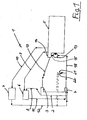
- the cooling system 1 schematically shows a cooling circuit of a cooling system 1 of a motor vehicle.
- the cooling system 1 essentially has a cooling module (coolant cooler) 2, from which via connecting lines 18, 19 by means of a water pump 13 and a thermostat 14 an internal combustion engine 5 can be supplied with coolant. In doing so, the funding of coolant via the water pump 13 to the cooling module (coolant cooler) 2 by means of the thermostat 14 only from a defined temperature.
- Parallel to Cooling module (coolant cooler) 2 which comes from the internal combustion engine 5 Coolant flows through the inlet line 19, the expansion tank 6 in turn can Coolant via an engine ventilation line 9 coming from the internal combustion engine (5) or Take up via a water cooler ventilation line 8 coming from the cooling module 2.
- a heating heat exchanger 7 via a combustion engine 5 coming heating flow line 10 are supplied with coolant.
- the cooling module 2 can be on the top Drain coolant through the radiator ventilation line 8 to the expansion tank 6. about a short-circuit line 15 (bypass line) can reverse coolant if necessary Direction from the Thermosat 14 into the water pump 13.
- additional lines of further, here not mentioned coolant-carrying devices through the water box 17 of the Cooling module 2 are passed.
- additional lines of further, here not mentioned coolant-carrying devices through the water box 17 of the Cooling module 2 are passed.
- According to an embodiment variant not shown here can be introduced at the front of the cooling module 2 and passed directly through it Filling line 11 and heating return line 12 combined into a single line his.
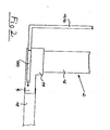
- FIG. 2 schematically shows an excerpt of a detail of the one shown in FIG. 1 Cooling system 1 shown.
- the coming from the expansion tank 6 are simplified Filling line 11 and the heating return line coming from the heating heat exchanger 7 12 combined into a common inlet line 11, 12, which on the vehicle front of the cooling module (coolant cooler) 2 directly through its water tank 17 passed in a lower area and in the end area of the radiator outlet 4 arranged at the mouth.
- this end area of the radiator outlet 4 is one any mixing of possibly higher temperature coolant from at least one an inlet line 11, 12 with possibly lower temperature coolant from the cooling module 2 without an adverse effect.
- Is located above the water tank 17 a cooling network 16 of the cooling module 2.
- the one which is guided through the water tank 17 can be Section of the at least one inlet line 11, 12 either a part of this inlet line 11, 12 itself or, alternatively, by a separate one, at least an inlet pipe 11, 12 connected pipe 20 may be given.
- the tube 20 can either be an integral part of the water box 17 or alternatively as a separate one Component inserted in the water tank 17 and soldered, welded or glued to it his.
- This can cause the otherwise existing disadvantage of heat loss in the low-load range of the internal combustion engine or when operating a vehicle heater be prevented.
Landscapes
- Engineering & Computer Science (AREA)
- Chemical & Material Sciences (AREA)
- Combustion & Propulsion (AREA)
- Mechanical Engineering (AREA)
- General Engineering & Computer Science (AREA)
- Cooling, Air Intake And Gas Exhaust, And Fuel Tank Arrangements In Propulsion Units (AREA)
Abstract
Description
- Fig. 1
- schematisch einen Kühlkreislauf eines Kühlsystems eines Kraftfahrzeuges und
- Fig. 2
- ausschnittsweise eine Detailzeichnung des Kühlsystems gemäß Fig. 1.
Claims (4)
- Kühlsystem (1) eines Kraftfahrzeuges, mit im wesentlichen einem mit einem Verbrennungsmotor (5) und einem Ausgleichsbehälter (6) leitungsmäßig in Verbindung stehenden Kühlmodul (Kühlmittelkühler) (2), dadurch gekennzeichnet, dass das Kühlmodul (Kühlmittelkühler) (2) in seinem unteren Bereich einen Wasserkasten (17) mit einem den Verbrennungsmotor (5) mit Kühlmittel mittelbar versorgenden Kühleraustritt (4) aufweist, wobei zusätzliches, dem Verbrennungsmotor (5) mittelbar zuführbares Kühlmittel von einem Ausgleichsbehälter (6) und/oder einem Heizungswärmetauscher (7) über wenigstens eine Zulaufleitung (11, 12) zuleitbar ist, welche durch den Wasserkasten (17) hindurchverlegt und in dessen Kühleraustritt (4) einmündet.
- Kühlsystem (1) nach Anspruch 1, dadurch gekennzeichnet, dass die wenigstens eine Zulaufleitung (11, 12) des Ausgleichsbehälters (6) und/oder des Heizungswärmetauschers (7) fahrzeugfrontseitig am Wasserkasten (17) des Kühlmoduls (Kühlmittelkühlers) (2) angeschlossen und in ihrer Verlängerung in einen endseitigen Bereich des Kühleraustrittes (4) einmündet.
- Kühlsystem (1) nach einem der Ansprüche 1 und 2, dadurch gekennzeichnet, dass der durch den Wasserkasten (17) hindurchgeführte Abschnitt der wenigstens einen Zulaufleitung (11, 12) entweder ein Teil dieser selbst ist, oder durch ein separates, an der wenigstens einen Zulaufleitung (11, 12) angeschlossenes Rohr (20) gegeben ist.
- Kühlsystem (1) nach einem der vorangegangenen Ansprüche 1 bis 3, dadurch gekennzeichnet, dass das Rohr (20) entweder integraler Bestandteil des Wasserkastens (17) ist, oder dass das Rohr (20) ein in den Wasserkasten (17) eingestecktes und mit diesem verlötetes, verschweißtes oder verklebtes, separates Bauteil ist.
Applications Claiming Priority (2)
| Application Number | Priority Date | Filing Date | Title |
|---|---|---|---|
| DE10207766 | 2002-02-23 | ||
| DE2002107766 DE10207766A1 (de) | 2002-02-23 | 2002-02-23 | Kühlsystem eines Kraftfahrzeuges |
Publications (3)
| Publication Number | Publication Date |
|---|---|
| EP1338771A2 true EP1338771A2 (de) | 2003-08-27 |
| EP1338771A3 EP1338771A3 (de) | 2004-03-24 |
| EP1338771B1 EP1338771B1 (de) | 2008-03-26 |
Family
ID=27635268
Family Applications (1)
| Application Number | Title | Priority Date | Filing Date |
|---|---|---|---|
| EP20030003000 Expired - Lifetime EP1338771B1 (de) | 2002-02-23 | 2003-02-12 | Kühlsystem eines Kraftfahrzeuges |
Country Status (2)
| Country | Link |
|---|---|
| EP (1) | EP1338771B1 (de) |
| DE (2) | DE10207766A1 (de) |
Cited By (1)
| Publication number | Priority date | Publication date | Assignee | Title |
|---|---|---|---|---|
| EP2282130A3 (de) * | 2009-06-30 | 2015-11-25 | Vaillant GmbH | Vorrichtung zur Reduzierung der Kühlmittelverdunstungsmenge im Kühlmittelkreislauf einer Kraft-Wärme-Kopplungsanlage |
Citations (1)
| Publication number | Priority date | Publication date | Assignee | Title |
|---|---|---|---|---|
| DE3245527A1 (de) | 1982-12-09 | 1984-06-14 | M.A.N. Maschinenfabrik Augsburg-Nürnberg AG, 8000 München | Kuehlmittelkreislauf fuer fluessigkeitsgekuehlte verbrennungsmotoren |
Family Cites Families (4)
| Publication number | Priority date | Publication date | Assignee | Title |
|---|---|---|---|---|
| DE4106297C2 (de) * | 1991-02-28 | 1994-09-29 | Behr Gmbh & Co | Querstromkühler, insbesondere Wasser/Luft-Kühler für Brennkraftmaschinen |
| DE4328448C2 (de) * | 1993-08-24 | 1995-08-17 | Behr Gmbh & Co | Wärmetauscher |
| DE4425440A1 (de) * | 1994-07-19 | 1996-01-25 | Valeo Motorkuehlsysteme Gmbh | Querstromkühler mit Entlüftung |
| DE19538239C1 (de) * | 1995-10-13 | 1997-04-24 | Daimler Benz Ag | Kühlmittelführung in einem Kühlkreislauf einer flüssigkeitsgekühlten Brennkraftmaschine |
-
2002
- 2002-02-23 DE DE2002107766 patent/DE10207766A1/de not_active Withdrawn
-
2003
- 2003-02-12 DE DE50309440T patent/DE50309440D1/de not_active Expired - Lifetime
- 2003-02-12 EP EP20030003000 patent/EP1338771B1/de not_active Expired - Lifetime
Patent Citations (1)
| Publication number | Priority date | Publication date | Assignee | Title |
|---|---|---|---|---|
| DE3245527A1 (de) | 1982-12-09 | 1984-06-14 | M.A.N. Maschinenfabrik Augsburg-Nürnberg AG, 8000 München | Kuehlmittelkreislauf fuer fluessigkeitsgekuehlte verbrennungsmotoren |
Cited By (1)
| Publication number | Priority date | Publication date | Assignee | Title |
|---|---|---|---|---|
| EP2282130A3 (de) * | 2009-06-30 | 2015-11-25 | Vaillant GmbH | Vorrichtung zur Reduzierung der Kühlmittelverdunstungsmenge im Kühlmittelkreislauf einer Kraft-Wärme-Kopplungsanlage |
Also Published As
| Publication number | Publication date |
|---|---|
| DE50309440D1 (de) | 2008-05-08 |
| EP1338771A3 (de) | 2004-03-24 |
| DE10207766A1 (de) | 2003-09-04 |
| EP1338771B1 (de) | 2008-03-26 |
Similar Documents
| Publication | Publication Date | Title |
|---|---|---|
| DE112007001140B4 (de) | Fahrzeug-Kühlungssystem mit gelenkten Strömen | |
| DE19954327B4 (de) | Verfahren und Vorrichtung zum Transport von in einem Kraftfahrzeug entstehender Wärmeenergie | |
| DE102008035955B4 (de) | Kühlstrategie | |
| DE10161851A1 (de) | Kühlkreislauf einer flüssigkeitsgekühlten Brennkraftmaschine | |
| EP1108572B1 (de) | Wärmetauschsystem für die Heizung eines Fahrzeugs mit Hybridantrieb | |
| DE10215262B4 (de) | Kühlsystem, insbesondere für einen Kraftfahrzeugmotor mit indirekter Ladeluftkühlung | |
| EP1111214A2 (de) | Kühl-Heiz-Kreis mit zwei Kühlern | |
| DE102004024289A1 (de) | Kühlsystem für ein Fahrzeug | |
| DD149920A5 (de) | Heizeinrichtung | |
| DE10344018B4 (de) | Kühlsystem eingerichtet für einen Verbrennungsmotor mit einem Heißwasserspeicher | |
| EP3530901A1 (de) | Brennkraftmaschine | |
| EP3530899A1 (de) | Kühlsystem und brennkraftmaschine | |
| DE102006020951A1 (de) | Kühlsystem für ein Fahrzeug und Verfahren zum Betreiben eines Kühlsystems | |
| DE102006044680A1 (de) | Verbrennungsmotor mit Turboladernachlaufkühlung | |
| DE102010001752A1 (de) | Kühlsystem | |
| DE10047081B4 (de) | Verfahren und Vorrichtung zur Kühlung einer Brennkraftmaschine | |
| DE102004021551A1 (de) | Kühlsystem, insbesondere für ein Kraftfahrzeug | |
| DE112018004425T5 (de) | Aktives Aufheizsystem und Aufheizverfahren | |
| DE19803885B4 (de) | Kühlkreisanordnung für eine flüssigkeitsgekühlte Brennkraftmaschine | |
| EP2149688B1 (de) | Kühlanordnung eines Kraftfahrzeuges | |
| DE102005046514A1 (de) | Brennkraftmaschine mit Wärmetauschsystem sowie Verfahren zum Wärmetausch in einer Brennkraftmaschine | |
| DE19907267B4 (de) | Kühlermodul für eine Brennkraftmaschine | |
| EP1338771B1 (de) | Kühlsystem eines Kraftfahrzeuges | |
| DE102012019091A1 (de) | Kurbelgehäuse für eine Verbrennungskraftmaschine sowie Verbrennungskraftmaschine mit einem solchen Kurbelgehäuse | |
| DE102010015106B4 (de) | Kühlmittelkreislauf für eine Brennkraftmaschine eines Kraftfahrzeugs |
Legal Events
| Date | Code | Title | Description |
|---|---|---|---|
| PUAI | Public reference made under article 153(3) epc to a published international application that has entered the european phase |
Free format text: ORIGINAL CODE: 0009012 |
|
| AK | Designated contracting states |
Designated state(s): AT BE BG CH CY CZ DE DK EE ES FI FR GB GR HU IE IT LI LU MC NL PT SE SI SK TR |
|
| AX | Request for extension of the european patent |
Extension state: AL LT LV MK RO |
|
| PUAL | Search report despatched |
Free format text: ORIGINAL CODE: 0009013 |
|
| AK | Designated contracting states |
Kind code of ref document: A3 Designated state(s): AT BE BG CH CY CZ DE DK EE ES FI FR GB GR HU IE IT LI LU MC NL PT SE SI SK TR |
|
| AX | Request for extension of the european patent |
Extension state: AL LT LV MK RO |
|
| 17P | Request for examination filed |
Effective date: 20040722 |
|
| AKX | Designation fees paid |
Designated state(s): DE FR IT NL SE |
|
| 17Q | First examination report despatched |
Effective date: 20070301 |
|
| GRAP | Despatch of communication of intention to grant a patent |
Free format text: ORIGINAL CODE: EPIDOSNIGR1 |
|
| GRAS | Grant fee paid |
Free format text: ORIGINAL CODE: EPIDOSNIGR3 |
|
| GRAA | (expected) grant |
Free format text: ORIGINAL CODE: 0009210 |
|
| AK | Designated contracting states |
Kind code of ref document: B1 Designated state(s): DE FR IT NL SE |
|
| REF | Corresponds to: |
Ref document number: 50309440 Country of ref document: DE Date of ref document: 20080508 Kind code of ref document: P |
|
| REG | Reference to a national code |
Ref country code: SE Ref legal event code: TRGR |
|
| ET | Fr: translation filed | ||
| PLBE | No opposition filed within time limit |
Free format text: ORIGINAL CODE: 0009261 |
|
| STAA | Information on the status of an ep patent application or granted ep patent |
Free format text: STATUS: NO OPPOSITION FILED WITHIN TIME LIMIT |
|
| 26N | No opposition filed |
Effective date: 20081230 |
|
| REG | Reference to a national code |
Ref country code: NL Ref legal event code: TD Effective date: 20110420 |
|
| REG | Reference to a national code |
Ref country code: FR Ref legal event code: CD |
|
| REG | Reference to a national code |
Ref country code: DE Ref legal event code: R081 Ref document number: 50309440 Country of ref document: DE Owner name: MAN TRUCK & BUS AG, DE Free format text: FORMER OWNER: MAN NUTZFAHRZEUGE AKTIENGESELLSCHAFT, 80995 MUENCHEN, DE Effective date: 20110518 |
|
| REG | Reference to a national code |
Ref country code: FR Ref legal event code: PLFP Year of fee payment: 14 |
|
| REG | Reference to a national code |
Ref country code: FR Ref legal event code: PLFP Year of fee payment: 15 |
|
| REG | Reference to a national code |
Ref country code: FR Ref legal event code: PLFP Year of fee payment: 16 |
|
| REG | Reference to a national code |
Ref country code: DE Ref legal event code: R081 Ref document number: 50309440 Country of ref document: DE Owner name: MAN TRUCK & BUS SE, DE Free format text: FORMER OWNER: MAN TRUCK & BUS AG, 80995 MUENCHEN, DE |
|
| PGFP | Annual fee paid to national office [announced via postgrant information from national office to epo] |
Ref country code: SE Payment date: 20220218 Year of fee payment: 20 Ref country code: NL Payment date: 20220224 Year of fee payment: 20 Ref country code: IT Payment date: 20220221 Year of fee payment: 20 Ref country code: FR Payment date: 20220224 Year of fee payment: 20 |
|
| PGFP | Annual fee paid to national office [announced via postgrant information from national office to epo] |
Ref country code: DE Payment date: 20220428 Year of fee payment: 20 |
|
| REG | Reference to a national code |
Ref country code: DE Ref legal event code: R071 Ref document number: 50309440 Country of ref document: DE |
|
| REG | Reference to a national code |
Ref country code: NL Ref legal event code: MK Effective date: 20230211 |
|
| REG | Reference to a national code |
Ref country code: SE Ref legal event code: EUG |