EP1338567A2 - Procédé et appareil d'épuration d'eau polluée par de l'huile, et notamment par des hydrocarbures, en émulsion - Google Patents
Procédé et appareil d'épuration d'eau polluée par de l'huile, et notamment par des hydrocarbures, en émulsion Download PDFInfo
- Publication number
- EP1338567A2 EP1338567A2 EP03002924A EP03002924A EP1338567A2 EP 1338567 A2 EP1338567 A2 EP 1338567A2 EP 03002924 A EP03002924 A EP 03002924A EP 03002924 A EP03002924 A EP 03002924A EP 1338567 A2 EP1338567 A2 EP 1338567A2
- Authority
- EP
- European Patent Office
- Prior art keywords
- water
- electrodes
- oil
- wall
- weir
- Prior art date
- Legal status (The legal status is an assumption and is not a legal conclusion. Google has not performed a legal analysis and makes no representation as to the accuracy of the status listed.)
- Withdrawn
Links
Images


Classifications
-
- C—CHEMISTRY; METALLURGY
- C02—TREATMENT OF WATER, WASTE WATER, SEWAGE, OR SLUDGE
- C02F—TREATMENT OF WATER, WASTE WATER, SEWAGE, OR SLUDGE
- C02F1/00—Treatment of water, waste water, or sewage
- C02F1/46—Treatment of water, waste water, or sewage by electrochemical methods
- C02F1/461—Treatment of water, waste water, or sewage by electrochemical methods by electrolysis
- C02F1/465—Treatment of water, waste water, or sewage by electrochemical methods by electrolysis by electroflotation
-
- B—PERFORMING OPERATIONS; TRANSPORTING
- B01—PHYSICAL OR CHEMICAL PROCESSES OR APPARATUS IN GENERAL
- B01D—SEPARATION
- B01D17/00—Separation of liquids, not provided for elsewhere, e.g. by thermal diffusion
- B01D17/02—Separation of non-miscible liquids
- B01D17/0205—Separation of non-miscible liquids by gas bubbles or moving solids
-
- B—PERFORMING OPERATIONS; TRANSPORTING
- B01—PHYSICAL OR CHEMICAL PROCESSES OR APPARATUS IN GENERAL
- B01D—SEPARATION
- B01D17/00—Separation of liquids, not provided for elsewhere, e.g. by thermal diffusion
- B01D17/02—Separation of non-miscible liquids
- B01D17/0208—Separation of non-miscible liquids by sedimentation
- B01D17/0211—Separation of non-miscible liquids by sedimentation with baffles
-
- B—PERFORMING OPERATIONS; TRANSPORTING
- B01—PHYSICAL OR CHEMICAL PROCESSES OR APPARATUS IN GENERAL
- B01D—SEPARATION
- B01D17/00—Separation of liquids, not provided for elsewhere, e.g. by thermal diffusion
- B01D17/02—Separation of non-miscible liquids
- B01D17/0208—Separation of non-miscible liquids by sedimentation
- B01D17/0214—Separation of non-miscible liquids by sedimentation with removal of one of the phases
-
- B—PERFORMING OPERATIONS; TRANSPORTING
- B01—PHYSICAL OR CHEMICAL PROCESSES OR APPARATUS IN GENERAL
- B01D—SEPARATION
- B01D17/00—Separation of liquids, not provided for elsewhere, e.g. by thermal diffusion
- B01D17/02—Separation of non-miscible liquids
- B01D17/04—Breaking emulsions
-
- B—PERFORMING OPERATIONS; TRANSPORTING
- B01—PHYSICAL OR CHEMICAL PROCESSES OR APPARATUS IN GENERAL
- B01D—SEPARATION
- B01D17/00—Separation of liquids, not provided for elsewhere, e.g. by thermal diffusion
- B01D17/06—Separation of liquids from each other by electricity
-
- C—CHEMISTRY; METALLURGY
- C02—TREATMENT OF WATER, WASTE WATER, SEWAGE, OR SLUDGE
- C02F—TREATMENT OF WATER, WASTE WATER, SEWAGE, OR SLUDGE
- C02F1/00—Treatment of water, waste water, or sewage
- C02F1/40—Devices for separating or removing fatty or oily substances or similar floating material
-
- C—CHEMISTRY; METALLURGY
- C02—TREATMENT OF WATER, WASTE WATER, SEWAGE, OR SLUDGE
- C02F—TREATMENT OF WATER, WASTE WATER, SEWAGE, OR SLUDGE
- C02F2101/00—Nature of the contaminant
- C02F2101/30—Organic compounds
- C02F2101/301—Detergents, surfactants
-
- C—CHEMISTRY; METALLURGY
- C02—TREATMENT OF WATER, WASTE WATER, SEWAGE, OR SLUDGE
- C02F—TREATMENT OF WATER, WASTE WATER, SEWAGE, OR SLUDGE
- C02F2101/00—Nature of the contaminant
- C02F2101/30—Organic compounds
- C02F2101/32—Hydrocarbons, e.g. oil
-
- C—CHEMISTRY; METALLURGY
- C02—TREATMENT OF WATER, WASTE WATER, SEWAGE, OR SLUDGE
- C02F—TREATMENT OF WATER, WASTE WATER, SEWAGE, OR SLUDGE
- C02F2103/00—Nature of the water, waste water, sewage or sludge to be treated
- C02F2103/44—Nature of the water, waste water, sewage or sludge to be treated from vehicle washing facilities
-
- C—CHEMISTRY; METALLURGY
- C02—TREATMENT OF WATER, WASTE WATER, SEWAGE, OR SLUDGE
- C02F—TREATMENT OF WATER, WASTE WATER, SEWAGE, OR SLUDGE
- C02F2201/00—Apparatus for treatment of water, waste water or sewage
- C02F2201/46—Apparatus for electrochemical processes
- C02F2201/461—Electrolysis apparatus
- C02F2201/46105—Details relating to the electrolytic devices
- C02F2201/4611—Fluid flow
Definitions
- the present invention belongs to the field of wastewater treatment, and more particularly to the treatment of water polluted by emulsions oils and water, especially hydrocarbons and water, emulsions whose constitution is favored by the presence of surfactants contained in detergents used during cleaning processes.
- the scope privileged is that of garages wastewater, after cleaning vehicles automobiles.
- An effective technique is that of passing wastewater through a bed of bacteria.
- This biological treatment has the distinction of being applicable to almost all pollution, and is particularly suitable for the treatment of water polluted by hydrocarbons. However, it has the disadvantage of a relatively low price. Student.
- the flocculation process in which the pollutants are coagulated, which gives sludge that is generally incinerated, is effective but its economic balance and ecological is bad.
- the present invention aims to provide a simple method and apparatus, with a ecological balance as favorable as that of biological installations, but cheaper.
- the method and the apparatus are specially adapted to garages.
- the invention consists first of all in a process for purifying water polluted by oil, and in particular by hydrocarbons, in emulsion, and containing surfactants, in which polluted water is caused to pass between, or around, at least two electrodes (3, 4) of opposite poles, the duration of the passage of said polluted water between or around said electrodes and the voltage, the intensity of the current and the distance between the electrodes being such that the field electric destabilizes the links between surfactants and oil molecules, oil molecules thus released being brought to the surface of the treated water, the water thus treated being drawn off below the level of the oil layer (5) and said layer of oil being removed.
- the voltage, the intensity of the current and the distance between the electrodes are such that the current flow in the water to be treated causes partial electrolysis and therefore a release of oxygen and hydrogen bubbles which form a current upward capable of entraining the oil molecules on the surface.
- the current intensity is at least 5 amps.
- the distance between the electrodes is between 5 and 30 mm.
- the negative electrode is made entirely or partly of metal.
- the positive electrode is made entirely or partly of polyester and carbon.
- the process is applied to water from vehicle cleaning automobiles.
- the invention then consists of a device for purifying water polluted by oil, and in particular by hydrocarbons, in emulsion, intended for the application of a process according to the description, also in its general form although in its particular embodiments mentioned above, which comprises at least one tank (1), capable of receiving polluted water, at least two electrodes (3, 4), at least one of which has a pole opposite to that of the one or more others, and placed so as to be at least partially submerged in water polluted when it at least partially fills the tank, at least one non-horizontal wall (8) capable of guiding the current of water between the electrodes or around these, at least one water outlet (6) after its passage between or around the electrodes, and at least one evacuator (7) oil, the discharge opening (6) being situated at a level lower than that of the spillway (7).
- the wall (8) of the apparatus is at least partially vertical.
- the non-horizontal wall (8) has an upper part (26) tilted.
- the water discharge mouth (6) after it has passed between the electrodes or around them leads to at least one airlock (10) in which the water pours out then passes through at least one weir (2) placed lower than the oil drainer (7) and allowing the discharge of purified water.
- the weir (2) of the airlock has a threshold (9) of adjustable height.
- the adjustment of the height of the threshold (9) of the weir (2) is made by a plate (17) fixed to the wall (18) which closes the airlock downstream, the fixing from said plate to said wall allowing the height of the plate to be adjusted by relative to the wall, said plate including the weir (2), and said wall (18) having at least one opening (19) which coincides at least partially with said weir in at least part of the positions given to said plate relative to said wall.
- the airlock (10) comprises at least two compartments (11, 13) separated from each other at least one non-horizontal partition (14) whose top exceeds the level of treated water and the bottom of which leaves a passage (16) located lower than the discharge outlet (6) and the weir (2) and located between the of them.
- the invention finally consists in the use of a method described above, in its general definition or in one or more of its forms of execution particular, in a device described above, in its general definition or in one or more of its particular embodiments.
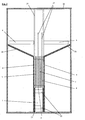
- Figure 1 is a longitudinal vertical section of an apparatus according to the invention.
- the arrows indicate the direction of water circulation in the appliance, except the single arrow going from right to left and showing the direction in which pours the separated oil from the water.
- Figure 2 is a cross section along AB of an apparatus according to the invention.
- Figure 3 is a top view of an apparatus according to the invention, in which the horizontal tops of the connector covers have been removed for allow a more complete view of the electrodes.
- the apparatus according to the invention comprises at least one tank 1 in which are placed several electrodes 3 and 4, the electrodes 3 being of opposite pole to that of the electrodes 4.
- the electrodes 3 alternate with the electrodes 4 and are placed vertically between two vertical walls 8 which enclose them.
- the polluted water is brought into the tank from below, by means of at least one conduit 20.
- the polluted water is guided by the walls 8 to mount between the electrodes; a small part of the water, in the embodiment presented here passes between an electrode and a wall 8 at place between two electrodes, but this has no practical consequences, the water still being subjected to an electric field.
- the emulsion formed by water and oil which constitute the polluted water is subjected to the current coming from the electrodes.
- This current preferably has an intensity of at least 5 amperes.
- the distance between the electrodes is preferably between 5 and 30 mm, and it is ideally 8 mm.
- the walls 8 are fixed here on a frame placed at the bottom of the tank and which consists essentially of two walls 21 connected by sleepers 22, the walls 8 being fixed against the walls 21.
- the electrodes 3 and 4 have a preferably rectangular plate shape surmounted on one side by a projection forming a vertical rectangle 23 or 24 a long side of which extends one of the sides of the electrode which are contiguous to the walls which close the tank transversely to the plane of the electrodes.
- the electrodes are arranged in parallel. There are four of them here and may be present in greater numbers. Positive electrodes alternate with negative electrodes.
- the vertical rectangular outgrowths 23 of electrodes of the same pole are placed on the same side, and the protrusions vertical rectangular 24 electrodes of the opposite pole are placed on the side opposite. This makes it possible to easily connect the electrodes of the same pole to the same Power source.
- the connections between the power source and the 23 or 24 vertical rectangular protrusions are protected by connector covers 25, which here have the form of two vertical section walls horizontal in U and covering the vertical rectangular outgrowths 23 and 24, as well as the electrical connections which supply them, said connections not shown here.
- the positive electrodes are preferably made up in whole or in part of polyester and carbon, and the negative electrodes are in principle metallic, in this case aluminum.
- the walls 8 preferably have an inclined upper part 26. Of the so, a flare is formed in which the water arrives after passing between the electrodes. This flaring allows the bubbles of oxygen and hydrogen which are are formed by electrolysis to relax, which promotes their movement ascending and also allows drops of oil to more easily reach the area. In addition, the surface being larger, the oil film is thinner.
- the oil layer on the surface doesn't just take the form of a film covering the surface of the water, but also that of a foam caused by oxygen and hydrogen bubbles, foam which is superimposed on the oil layer which forms on the surface of the water.
- the production of oxygen bubbles not only has the mechanical effect mentioned above, but also decreases the chemical demand for oxygen by combining with part of the surfactants, which thus precipitate at the bottom of the tank and which can be extracted from time to time.
- An oil drainer 7 is placed in the outer transverse wall of the tank, above the level of the top of the flare formed by the two parts inclined upper 26 of the walls 8.
- This spillway 7 simply consists of one or more orifices, which here have a pouring spout 27.
- a discharge mouth 6 of the water after its passage between the electrodes is provided on the other side, in the transverse wall which faces the spout. That mouth outlet 6 here has the form of two rectangular openings placed horizontally at a level lower than that of the spillway 7. It is indeed it is necessary to withdraw the purified water below layer 5 of oil and foam floating on the surface. Purified water passes through the drain in an airlock 10. The edge of the airlock is higher than the exhaust outlet 6.
- This airlock is divided into at least two compartments 11 and 13 separated from each other by at least one non-horizontal partition 14, and preferably vertical.
- the top of this partition exceeds the level of the treated water.
- a passage 16 is provided at bottom of this partition, lower than the exhaust outlet 6.
- the second compartment 13, downstream, has a weir 2, formed here in a plate 17 adjoining the transverse wall 18 which closes the airlock.
- Weir 2 is placed lower than the oil and foam evacuator 7.
- the weir here takes the shape of a rectangular opening in plate 17. Plate 17 is fixed against the transverse wall 18 so that it can slide vertically with respect to this wall, which is fixed.
- the transverse wall 18 itself has an opening 19, here rectangular, also placed more lower than the oil drainer 7.
- the threshold of opening 19 is about one centimeter lower than the threshold of the mouth outlet 6.
- the threshold 9 of the weir 2 is at the same height as the threshold of the opening 19, or slightly higher.
- the threshold 9 is higher by a few centimeters. In such a case, the level goes back up as well in the airlock as in the tank.
- raising the threshold 9 we also raise the water level in all of the device, which increases the height between the mouth discharge 6 from the bottom of the oil layer 5 which floats on the surface of the water in tank 1. In this way, the oil layer is also allowed to take on a greater thickness without the oil reaching the outlet 6.
- the height adjustment of the plate 17, and therefore of the weir 2 and the threshold 9, is done here by means of vertical screws 12, which are screwed into a thread made in a horizontal flange 15 integral with the plate 17 and placed at its Mountain peak. This rim surmounts the top of the wall 18. The screw comes to rest on the top of the wall 18. To mount the plate 17, simply screw the screw (s) 12.
- the device is surmounted by two removable covers 28, for example made of transparent PVC, so as to allow the user to see if the process is proceeding properly.
- Apparatus and method can be used for wastewater treatment originating in particular from the cleaning of motor vehicles, including possibly aircraft, boats, or railways.
- Field of application is not however limited to such devices, but extends to any purification of water polluted by oils forming an emulsion thanks to the presence of surfactants, such emulsions forming as a result of any cleaning of elements or devices soiled with oils.
Landscapes
- Chemical & Material Sciences (AREA)
- Chemical Kinetics & Catalysis (AREA)
- Physics & Mathematics (AREA)
- Thermal Sciences (AREA)
- Hydrology & Water Resources (AREA)
- Life Sciences & Earth Sciences (AREA)
- Engineering & Computer Science (AREA)
- Environmental & Geological Engineering (AREA)
- Water Supply & Treatment (AREA)
- Organic Chemistry (AREA)
- Analytical Chemistry (AREA)
- Electrochemistry (AREA)
- General Chemical & Material Sciences (AREA)
- Water Treatment By Electricity Or Magnetism (AREA)
Abstract
Description
Claims (15)
- Procédé d'épuration d'eau polluée par de l'huile, et notamment par des hydrocarbures, en émulsion, et contenant des tensioactifs, caractérisé en ce que l'eau polluée est amenée à passer entre, ou autour de, au moins deux électrodes (3, 4) de pôles opposés, en ce que la durée du passage de ladite eau polluée entre lesdites électrodes ou autour de celles-ci ainsi que la tension, l'intensité du courant et la distance entre les électrodes sont telles que le champ électrique déstabilise les liens entre les tensioactifs et les molécules d'huile, en ce que les molécules d'huile ainsi dégagées sont amenées à la surface des eaux traitées, en ce que l'eau ainsi traitée est soutirée au-dessous du niveau de la couche d'huile (5) et en ce que ladite couche d'huile est évacuée.
- Procédé selon la revendication 1, caractérisée en ce que la tension, l'intensité du courant et la distance entre les électrodes sont telles que le passage du courant dans l'eau à traiter provoque une électrolyse partielle et par conséquent un dégagement de bulles d'oxygène et d'hydrogène qui forment un courant ascendant propre à entraíner à la surface les molécules d'huile.
- Procédé selon l'une des revendications 1 ou 2, caractérisé en ce que l'intensité du courant est de 5 ampères au moins.
- Procédé selon l'une des revendications 1 à 3, caractérisé en ce que la distance les électrodes est comprise entre 5 et 30 mm.
- Procédé selon l'une des revendications 1 à 4, caractérisé en ce que l'électrode négative est constituée en tout ou en partie de métal.
- Procédé selon l'une des revendications 1 à 5, caractérisé en ce que l'électrode positive est constituée en tout ou en partie de polyester et de carbone.
- Procédé selon l'une des revendications 1 à 6, caractérisé en ce qu'il est appliqué à des eaux provenant du nettoyage de véhicules automobiles.
- Appareil d'épuration d'eau polluée par de l'huile, et notamment par des hydrocarbures, en émulsion, destiné à l'application d'un procédé selon l'une des revendications 1 à 7, caractérisé en ce qu'il comprend au moins une cuve (1), apte à recevoir l'eau polluée, au moins deux électrodes (3, 4), dont au moins une a un pôle opposé à celui de la ou des autres, et placées de façon à être au moins partiellement plongées dans l'eau polluée lorsque celle-ci remplit au moins partiellement la cuve, au moins une paroi (8) non horizontale apte à guider le courant d'eau entre les électrodes ou autour de celles-ci, au moins une bouche d'évacuation (6) de l'eau après son passage entre les électrodes ou autour de celles-ci, et au moins un évacuateur (7) de l'huile, la bouche d'évacuation (6) étant située à un niveau inférieur à celui de l'évacuateur (7).
- Appareil selon la revendication 8, caractérisé en ce que la paroi (8) est au moins partiellement verticale.
- Appareil selon l'une des revendications 8 ou 9, caractérisé en ce que la paroi non horizontale (8) présente une partie supérieure (26) inclinée.
- Appareil selon l'une des revendications 8 à 10, caractérisé en ce que la bouche d'évacuation (6) de l'eau après son passage entre les électrodes ou autour de celles-ci débouche sur au moins un sas (10) dans lequel l'eau se déverse puis passe dans au moins un déversoir (2) placé plus bas que l'évacuateur (7) de l'huile et permettant l'évacuation de l'eau épurée.
- Appareil selon la revendication 11, caractérisé en ce que le déversoir (2) du sas a un seuil (9) de hauteur réglable.
- Appareil selon la revendication 12, caractérisé en ce que le réglage de la hauteur du seuil (9) du déversoir (2) se fait par une plaque (17) fixée à la paroi (18) qui ferme le sas en aval, la fixation de ladite plaque à ladite paroi permettant de régler la hauteur de la plaque par rapport à la paroi, ladite plaque incluant le déversoir (2), et ladite paroi (18) présentant au moins une ouverture (19) qui coïncide au moins partiellement avec ledit déversoir dans au moins une partie des positions données à ladite plaque par rapport à ladite paroi.
- Appareil selon l'une des revendications 10 à 13, caractérisé en ce que le sas (10) comprend au moins deux compartiments (11, 13) séparés l'un de l'autre part au moins une cloison non horizontale (14) dont le haut dépasse le niveau de l'eau traitée et dont le bas laisse un passage (16) situé plus bas que la bouche d'évacuation (6) et le déversoir (2) et situé entre les deux.
- Utilisation d'un procédé selon l'une des revendications 1 à 7 dans un appareil selon l'une des revendications 8 à 14.
Applications Claiming Priority (2)
| Application Number | Priority Date | Filing Date | Title |
|---|---|---|---|
| CH2232002 | 2002-02-11 | ||
| CH00223/02A CH694728A5 (fr) | 2002-02-11 | 2002-02-11 | Procédé et appareil d'épuration d'eau polluée par de l'huile, et notamment par des hydrocarbures, en émulsion. |
Publications (2)
| Publication Number | Publication Date |
|---|---|
| EP1338567A2 true EP1338567A2 (fr) | 2003-08-27 |
| EP1338567A3 EP1338567A3 (fr) | 2004-10-20 |
Family
ID=27626689
Family Applications (1)
| Application Number | Title | Priority Date | Filing Date |
|---|---|---|---|
| EP03002924A Withdrawn EP1338567A3 (fr) | 2002-02-11 | 2003-02-10 | Procédé et appareil d'épuration d'eau polluée par de l'huile, et notamment par des hydrocarbures, en émulsion |
Country Status (2)
| Country | Link |
|---|---|
| EP (1) | EP1338567A3 (fr) |
| CH (1) | CH694728A5 (fr) |
Cited By (2)
| Publication number | Priority date | Publication date | Assignee | Title |
|---|---|---|---|---|
| CN100344346C (zh) * | 2005-06-02 | 2007-10-24 | 上海市闵行第二中学 | 一种脱排油烟机集油盒中废油的处理方法 |
| NL2011805C2 (en) * | 2013-11-14 | 2015-05-19 | Brilliant Water Invest Ii B V | Electrolysis unit for waste water treatment. |
Families Citing this family (1)
| Publication number | Priority date | Publication date | Assignee | Title |
|---|---|---|---|---|
| CN108706789B (zh) * | 2018-05-17 | 2020-09-29 | 山西华仕低碳技术研究院有限公司 | 一种煤化工废水处理破乳气浮除油装置 |
Family Cites Families (4)
| Publication number | Priority date | Publication date | Assignee | Title |
|---|---|---|---|---|
| US3959131A (en) * | 1974-10-17 | 1976-05-25 | Swift & Company | Apparatus and method for removing pollutants from wastewater |
| US4732661A (en) * | 1985-10-24 | 1988-03-22 | Mercer International, Inc. | Electrolytic purification system |
| DE4024424A1 (de) * | 1990-08-01 | 1992-02-06 | Iwatech Konrad Gmbh | Verfahren und vorrichtung zum aufbereiten von verunreinigten fluessigkeiten |
| DE10035535A1 (de) * | 2000-07-21 | 2002-01-31 | Ader Abwasser Anlagen Ag | Verfahren und Vorrichtung zur Reinigung von Abwässern |
-
2002
- 2002-02-11 CH CH00223/02A patent/CH694728A5/fr not_active IP Right Cessation
-
2003
- 2003-02-10 EP EP03002924A patent/EP1338567A3/fr not_active Withdrawn
Cited By (3)
| Publication number | Priority date | Publication date | Assignee | Title |
|---|---|---|---|---|
| CN100344346C (zh) * | 2005-06-02 | 2007-10-24 | 上海市闵行第二中学 | 一种脱排油烟机集油盒中废油的处理方法 |
| NL2011805C2 (en) * | 2013-11-14 | 2015-05-19 | Brilliant Water Invest Ii B V | Electrolysis unit for waste water treatment. |
| WO2015072855A3 (fr) * | 2013-11-14 | 2015-07-09 | Brilliant Water Investments Ii B.V. | Unité d'électrolyse pour traitement des eaux usées |
Also Published As
| Publication number | Publication date |
|---|---|
| EP1338567A3 (fr) | 2004-10-20 |
| CH694728A5 (fr) | 2005-06-30 |
Similar Documents
| Publication | Publication Date | Title |
|---|---|---|
| CA1091371A (fr) | Appareil monobloc pour l'epuration des eaux | |
| FR2596437A1 (fr) | Fosse septique toutes eaux | |
| JPH10511893A (ja) | 液体、気体及び粒子材料を含む液体のための沈降装置、並びに、それを備えた洗浄装置及び排水を洗浄するための方法 | |
| LU82489A1 (fr) | Fosse d'aisances septique mobile | |
| EP0836876B1 (fr) | Décanteur lamellaire pour le traitement de liquide chargé | |
| EP1338567A2 (fr) | Procédé et appareil d'épuration d'eau polluée par de l'huile, et notamment par des hydrocarbures, en émulsion | |
| EP0933110B1 (fr) | Dispositif de clarification d'un liquide chargé par flottation | |
| WO2010081903A1 (fr) | Dispositif d'enrobage avec un materiau polymere floculant a l'etat liquide de grains de ballast utilises pour le traitement de l'eau par floculation lestee, et installation correspondante | |
| FR2921649A1 (fr) | Reacteur biologique sequentiel a selecteur pour le traitement d'eaux residuaires urbaines ou industrielles | |
| JP2001170617A (ja) | 泡沫分離装置及びそれを用いた水浄化システム | |
| CA1297213C (fr) | Procede et dispositif pour le traitement des eaux usees | |
| EP0884281B1 (fr) | Procédé et installation pour le traitement d'effluents chargés en matières organiques | |
| FR2897053A1 (fr) | Dispositif de couverture de bassin de traitement d'effluents liquides | |
| JP4625291B2 (ja) | 汚泥処理装置 | |
| JP2008207089A (ja) | 汚水処理装置及び汚水処理方法 | |
| CN211255561U (zh) | 一种污水处理用沉淀池 | |
| JPH09201586A (ja) | 電解浮上式浄水装置 | |
| RU2333893C1 (ru) | Устройство очистки воды | |
| FR3069002A1 (fr) | Structure pour baignade a systeme de filtration integre | |
| FR2873679A1 (fr) | Procede de traitement de liquides pollues par photocatalyse et dispositifs faisant application | |
| FR2880548A1 (fr) | Decanteur lamellaire destine au traitement des eaux usees et comportant un dispositif de recuperation des flottants | |
| FR3048690A1 (fr) | Flottateur a air dissous a entrees et sorties multiples | |
| CH700406A2 (fr) | Procédé d'épuration d'eau polluée au moyen d'un bioréacteur a membrane. | |
| FR2496081A1 (fr) | Appareil d'epuration electrochimique de liquides pollues | |
| FR2701405A1 (fr) | Séparateur lamellaire en "V". |
Legal Events
| Date | Code | Title | Description |
|---|---|---|---|
| PUAI | Public reference made under article 153(3) epc to a published international application that has entered the european phase |
Free format text: ORIGINAL CODE: 0009012 |
|
| AK | Designated contracting states |
Designated state(s): AT BE BG CH CY CZ DE DK EE ES FI FR GB GR HU IE IT LI LU MC NL PT SE SI SK TR |
|
| AX | Request for extension of the european patent |
Extension state: AL LT LV MK RO |
|
| PUAL | Search report despatched |
Free format text: ORIGINAL CODE: 0009013 |
|
| AK | Designated contracting states |
Kind code of ref document: A3 Designated state(s): AT BE BG CH CY CZ DE DK EE ES FI FR GB GR HU IE IT LI LU MC NL PT SE SI SK TR |
|
| AX | Request for extension of the european patent |
Extension state: AL LT LV MK RO |
|
| RIC1 | Information provided on ipc code assigned before grant |
Ipc: 7C 02F 1/465 B Ipc: 7C 02F 1/40 B Ipc: 7C 02F 1/461 A |
|
| 17P | Request for examination filed |
Effective date: 20041202 |
|
| AKX | Designation fees paid |
Designated state(s): AT BE BG CH CY CZ DE DK EE ES FI FR GB GR HU IE IT LI LU MC NL PT SE SI SK TR |
|
| STAA | Information on the status of an ep patent application or granted ep patent |
Free format text: STATUS: THE APPLICATION IS DEEMED TO BE WITHDRAWN |
|
| 18D | Application deemed to be withdrawn |
Effective date: 20090826 |