EP1338489A1 - Maítre-cylindre pour systeme de freinage electro-hydraulique - Google Patents
Maítre-cylindre pour systeme de freinage electro-hydraulique Download PDFInfo
- Publication number
- EP1338489A1 EP1338489A1 EP03003874A EP03003874A EP1338489A1 EP 1338489 A1 EP1338489 A1 EP 1338489A1 EP 03003874 A EP03003874 A EP 03003874A EP 03003874 A EP03003874 A EP 03003874A EP 1338489 A1 EP1338489 A1 EP 1338489A1
- Authority
- EP
- European Patent Office
- Prior art keywords
- spring
- master cylinder
- turn
- cartridge
- piston
- Prior art date
- Legal status (The legal status is an assumption and is not a legal conclusion. Google has not performed a legal analysis and makes no representation as to the accuracy of the status listed.)
- Granted
Links
- 239000012530 fluid Substances 0.000 claims abstract description 17
- 230000035807 sensation Effects 0.000 claims description 15
- 238000004088 simulation Methods 0.000 claims description 11
- 238000004891 communication Methods 0.000 claims description 9
- 238000006073 displacement reaction Methods 0.000 claims description 9
- 238000001514 detection method Methods 0.000 claims description 6
- 230000000712 assembly Effects 0.000 claims description 3
- 238000000429 assembly Methods 0.000 claims description 3
- 238000012986 modification Methods 0.000 claims description 3
- 230000004048 modification Effects 0.000 claims description 3
- 239000007788 liquid Substances 0.000 claims 1
- 238000006243 chemical reaction Methods 0.000 abstract description 18
- 230000000750 progressive effect Effects 0.000 description 4
- 238000010521 absorption reaction Methods 0.000 description 3
- 230000006835 compression Effects 0.000 description 3
- 238000007906 compression Methods 0.000 description 3
- 229920001971 elastomer Polymers 0.000 description 3
- 239000000806 elastomer Substances 0.000 description 3
- 230000006978 adaptation Effects 0.000 description 2
- 230000003247 decreasing effect Effects 0.000 description 2
- 230000005489 elastic deformation Effects 0.000 description 2
- 230000006870 function Effects 0.000 description 2
- 239000000463 material Substances 0.000 description 2
- 238000000034 method Methods 0.000 description 2
- 101100096884 Rattus norvegicus Sult1e1 gene Proteins 0.000 description 1
- 101150034157 Sult1e1 gene Proteins 0.000 description 1
- 238000013459 approach Methods 0.000 description 1
- 239000002131 composite material Substances 0.000 description 1
- 238000010586 diagram Methods 0.000 description 1
- 238000009434 installation Methods 0.000 description 1
- 238000009413 insulation Methods 0.000 description 1
- 230000002093 peripheral effect Effects 0.000 description 1
- 238000007789 sealing Methods 0.000 description 1
- 238000000926 separation method Methods 0.000 description 1
Images


Classifications
-
- B—PERFORMING OPERATIONS; TRANSPORTING
- B60—VEHICLES IN GENERAL
- B60T—VEHICLE BRAKE CONTROL SYSTEMS OR PARTS THEREOF; BRAKE CONTROL SYSTEMS OR PARTS THEREOF, IN GENERAL; ARRANGEMENT OF BRAKING ELEMENTS ON VEHICLES IN GENERAL; PORTABLE DEVICES FOR PREVENTING UNWANTED MOVEMENT OF VEHICLES; VEHICLE MODIFICATIONS TO FACILITATE COOLING OF BRAKES
- B60T8/00—Arrangements for adjusting wheel-braking force to meet varying vehicular or ground-surface conditions, e.g. limiting or varying distribution of braking force
- B60T8/32—Arrangements for adjusting wheel-braking force to meet varying vehicular or ground-surface conditions, e.g. limiting or varying distribution of braking force responsive to a speed condition, e.g. acceleration or deceleration
- B60T8/34—Arrangements for adjusting wheel-braking force to meet varying vehicular or ground-surface conditions, e.g. limiting or varying distribution of braking force responsive to a speed condition, e.g. acceleration or deceleration having a fluid pressure regulator responsive to a speed condition
- B60T8/40—Arrangements for adjusting wheel-braking force to meet varying vehicular or ground-surface conditions, e.g. limiting or varying distribution of braking force responsive to a speed condition, e.g. acceleration or deceleration having a fluid pressure regulator responsive to a speed condition comprising an additional fluid circuit including fluid pressurising means for modifying the pressure of the braking fluid, e.g. including wheel driven pumps for detecting a speed condition, or pumps which are controlled by means independent of the braking system
- B60T8/4072—Systems in which a driver input signal is used as a control signal for the additional fluid circuit which is normally used for braking
- B60T8/4081—Systems with stroke simulating devices for driver input
- B60T8/409—Systems with stroke simulating devices for driver input characterised by details of the stroke simulating device
-
- B—PERFORMING OPERATIONS; TRANSPORTING
- B60—VEHICLES IN GENERAL
- B60T—VEHICLE BRAKE CONTROL SYSTEMS OR PARTS THEREOF; BRAKE CONTROL SYSTEMS OR PARTS THEREOF, IN GENERAL; ARRANGEMENT OF BRAKING ELEMENTS ON VEHICLES IN GENERAL; PORTABLE DEVICES FOR PREVENTING UNWANTED MOVEMENT OF VEHICLES; VEHICLE MODIFICATIONS TO FACILITATE COOLING OF BRAKES
- B60T11/00—Transmitting braking action from initiating means to ultimate brake actuator without power assistance or drive or where such assistance or drive is irrelevant
- B60T11/10—Transmitting braking action from initiating means to ultimate brake actuator without power assistance or drive or where such assistance or drive is irrelevant transmitting by fluid means, e.g. hydraulic
- B60T11/16—Master control, e.g. master cylinders
- B60T11/20—Tandem, side-by-side, or other multiple master cylinder units
-
- B—PERFORMING OPERATIONS; TRANSPORTING
- B60—VEHICLES IN GENERAL
- B60T—VEHICLE BRAKE CONTROL SYSTEMS OR PARTS THEREOF; BRAKE CONTROL SYSTEMS OR PARTS THEREOF, IN GENERAL; ARRANGEMENT OF BRAKING ELEMENTS ON VEHICLES IN GENERAL; PORTABLE DEVICES FOR PREVENTING UNWANTED MOVEMENT OF VEHICLES; VEHICLE MODIFICATIONS TO FACILITATE COOLING OF BRAKES
- B60T13/00—Transmitting braking action from initiating means to ultimate brake actuator with power assistance or drive; Brake systems incorporating such transmitting means, e.g. air-pressure brake systems
- B60T13/10—Transmitting braking action from initiating means to ultimate brake actuator with power assistance or drive; Brake systems incorporating such transmitting means, e.g. air-pressure brake systems with fluid assistance, drive, or release
- B60T13/66—Electrical control in fluid-pressure brake systems
- B60T13/68—Electrical control in fluid-pressure brake systems by electrically-controlled valves
- B60T13/686—Electrical control in fluid-pressure brake systems by electrically-controlled valves in hydraulic systems or parts thereof
-
- B—PERFORMING OPERATIONS; TRANSPORTING
- B60—VEHICLES IN GENERAL
- B60T—VEHICLE BRAKE CONTROL SYSTEMS OR PARTS THEREOF; BRAKE CONTROL SYSTEMS OR PARTS THEREOF, IN GENERAL; ARRANGEMENT OF BRAKING ELEMENTS ON VEHICLES IN GENERAL; PORTABLE DEVICES FOR PREVENTING UNWANTED MOVEMENT OF VEHICLES; VEHICLE MODIFICATIONS TO FACILITATE COOLING OF BRAKES
- B60T13/00—Transmitting braking action from initiating means to ultimate brake actuator with power assistance or drive; Brake systems incorporating such transmitting means, e.g. air-pressure brake systems
- B60T13/74—Transmitting braking action from initiating means to ultimate brake actuator with power assistance or drive; Brake systems incorporating such transmitting means, e.g. air-pressure brake systems with electrical assistance or drive
- B60T13/745—Transmitting braking action from initiating means to ultimate brake actuator with power assistance or drive; Brake systems incorporating such transmitting means, e.g. air-pressure brake systems with electrical assistance or drive acting on a hydraulic system, e.g. a master cylinder
-
- B—PERFORMING OPERATIONS; TRANSPORTING
- B60—VEHICLES IN GENERAL
- B60T—VEHICLE BRAKE CONTROL SYSTEMS OR PARTS THEREOF; BRAKE CONTROL SYSTEMS OR PARTS THEREOF, IN GENERAL; ARRANGEMENT OF BRAKING ELEMENTS ON VEHICLES IN GENERAL; PORTABLE DEVICES FOR PREVENTING UNWANTED MOVEMENT OF VEHICLES; VEHICLE MODIFICATIONS TO FACILITATE COOLING OF BRAKES
- B60T7/00—Brake-action initiating means
- B60T7/02—Brake-action initiating means for personal initiation
- B60T7/04—Brake-action initiating means for personal initiation foot actuated
- B60T7/042—Brake-action initiating means for personal initiation foot actuated by electrical means, e.g. using travel or force sensors
-
- B—PERFORMING OPERATIONS; TRANSPORTING
- B60—VEHICLES IN GENERAL
- B60T—VEHICLE BRAKE CONTROL SYSTEMS OR PARTS THEREOF; BRAKE CONTROL SYSTEMS OR PARTS THEREOF, IN GENERAL; ARRANGEMENT OF BRAKING ELEMENTS ON VEHICLES IN GENERAL; PORTABLE DEVICES FOR PREVENTING UNWANTED MOVEMENT OF VEHICLES; VEHICLE MODIFICATIONS TO FACILITATE COOLING OF BRAKES
- B60T8/00—Arrangements for adjusting wheel-braking force to meet varying vehicular or ground-surface conditions, e.g. limiting or varying distribution of braking force
- B60T8/32—Arrangements for adjusting wheel-braking force to meet varying vehicular or ground-surface conditions, e.g. limiting or varying distribution of braking force responsive to a speed condition, e.g. acceleration or deceleration
- B60T8/34—Arrangements for adjusting wheel-braking force to meet varying vehicular or ground-surface conditions, e.g. limiting or varying distribution of braking force responsive to a speed condition, e.g. acceleration or deceleration having a fluid pressure regulator responsive to a speed condition
- B60T8/40—Arrangements for adjusting wheel-braking force to meet varying vehicular or ground-surface conditions, e.g. limiting or varying distribution of braking force responsive to a speed condition, e.g. acceleration or deceleration having a fluid pressure regulator responsive to a speed condition comprising an additional fluid circuit including fluid pressurising means for modifying the pressure of the braking fluid, e.g. including wheel driven pumps for detecting a speed condition, or pumps which are controlled by means independent of the braking system
- B60T8/4072—Systems in which a driver input signal is used as a control signal for the additional fluid circuit which is normally used for braking
- B60T8/4081—Systems with stroke simulating devices for driver input
Definitions
- the present invention relates mainly to a master cylinder for a system of electro-hydraulic braking with improved means for simulating the pedal feel and an electro-hydraulic braking system including such master cylinder.
- Electro-hydraulic braking systems have a simulating master cylinder in normal operation, the mechanical reaction of a conventional braking circuit felt at the brake pedal by a driver, and means for detecting the action of the driver on the brake pedal, the detection means sending the information to a computer which generates the order to a hydraulic pump to send brake fluid under brake pressure.
- the master cylinder supplies pressurized brake fluid to the brakes as in a conventional brake system.
- the master cylinder for an electro-hydraulic braking system of known type have a body of substantially cylindrical shape in which a bore divided into at least one supply chamber and one working chamber by a piston mounted to slide tightly in the bore and actuated by a rod actuation connected to a brake pedal
- the piston allows a rest communication between the two chambers and a tight separation of the two chambers during a braking action.
- the feed chamber is connected so waterproof to a brake fluid reservoir and the working chamber is in operation normal connected to a pedal sensation simulation cartridge or pedal feeling and in degraded operation with at least one brake arranged at the level of a wheel.
- the pedal feel cartridge comprises an envelope delimiting a substantially cylindrical chamber in which slides a piston subjected in normal operation during a braking phase by a first face to the pressurized brake fluid supplied by the working chamber and by a second face. at a first end of an elastic means, the second end of the elastic means pressing against the bottom of the chamber opposite the piston.
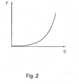
- the elastic means makes it possible to simulate the mechanical reaction of a conventional braking circuit, which corresponds to a relation linking the force to the pedal as a function of the stroke of the pedal.
- the characteristic curve of this relationship includes at least a first part corresponding to the absorption of the braking circuit at the start of the braking phase, then a second part corresponding to an increasingly significant reaction with the increase in the braking level.
- the elastic means of known type for pedal feel cartridges are therefore very complex and expensive, they comprise for example several helical springs, of different loads, with constant pitch and with variable pitch, elastomer elements to simulate the absorption of the circuit.
- the assembly is long and consequently increases the cost price due to the large number of parts necessary to correctly simulate a conventional pedal reaction.
- the electro-hydraulic braking systems allow excellent control of the braking and of the vehicle, however the means of simulating the reaction of the circuit braking are relatively complex and require precise adjustment and Consequently, it is not possible to apply them to a wide range of vehicles.
- a master cylinder comprising a cartridge for simulating the pedal sensation comprising an elastic means reproducing the reaction of a circuit conventional braking, the elastic means comprising a first helical spring and mobile support means for at least one turn of the first helical spring and allowing at least one modification of the stiffness of the elastic means.
- the elastic means comprises first and second springs coaxial helicals, the turns of the second spring being arranged in the intervals separating the turns of the first spring, the turns of the first spring which, when displacement of the piston, move towards each other and come to bear against the turns of the second spring which are then themselves displaced in the direction of displacement of the piston, causing an increase in the stiffness of the elastic means according to the present invention substantially continuous simulating the reaction to the pedal of brake of a conventional brake system.
- the main object of the present invention is a master cylinder for electro-hydraulic braking comprising a body pierced with a bore, a piston mounted at sealed sliding in the bore and axially dividing the bore into a chamber supply connected tightly to a brake fluid reservoir and in a working chamber and a pedal sensation simulation cartridge, said chamber being in communication during normal operation with the interior of the pedal feel simulation cartridge and in degraded operation with at at least one brake arranged at a wheel, said cartridge comprising a piston likely to be subjected by a first face to the brake fluid under pressure supplied by the working chamber, and subjected by a second face to an elastic means with stiffness variable characterized in that the elastic means comprises at least one first spring helical and a second helical spring, the first spring comprising first turns and being mounted in support between the second face of the piston of the cartridge and a bottom of the cartridge, the second spring comprising second turns and being mounted coaxially at the first spring so that the elastic means comprises formed assemblies of a leading turn Ste of the first spring and
- the present invention also relates to a master cylinder characterized in that the leading coil is separated from the driven coil by a monotonically varying distance on a turn of the turn.
- the present invention also relates to a master cylinder characterized in that the variation in the distance between the driven turn and the leading turn differs for each together.
- the present invention also relates to a master cylinder characterized in that the first spring is a helical spring with turns of substantially circular cross section and that the second spring is a helical spring with turns of substantially cross section cuboid.
- the present invention also relates to a master cylinder characterized in that the turns of the first spring are separated by a constant axial distance.
- the present invention also relates to a master cylinder characterized in that the turns of the second spring are separated by a constant axial distance.
- the present invention also relates to a master cylinder characterized in that the cartridge comprises means for adjusting the simulated pedal feeling allowing the modification of the relative angular position of the driven turn relative to the driving turn of the same assembly.
- the present invention also relates to a master cylinder characterized in that said adjustment means comprises a stepping electric motor allowing a rotation movement of the second spring.
- the present invention also relates to an electro-hydraulic braking system
- an electro-hydraulic braking system comprising means for detecting the braking action of the driver, a computer receiving the information from the detection means and generating orders control to cause the actuation of at least one brake arranged at the level of a wheel, a pressure generator receiving the command from the computer to send pressurized fluid in the brakes, a master cylinder allowing the simulation of the pedal feel during normal operation and serving as a brake fluid source under pressure in degraded operation, and solenoid valves to interrupt the communication between said master cylinder and the brakes in normal operation, characterized in that said master cylinder is a master cylinder according to the invention.
- the present invention also relates to a braking system characterized in that that the pressure generator is an electric pump.
- a master cylinder of known type comprising a body 2 of longitudinal axis X pierced with a bore 4 of axis X blind, divided into a primary hydraulic circuit 6 and a secondary hydraulic circuit 8
- the primary and secondary hydraulic circuits being of similar structure we will only describe the primary circuit 6.
- the primary circuit 6 comprises a hydraulic piston 10 mounted for leaktight sliding in the bore 4 by means of lip seal 12 mounted in an annular groove 14 formed on the periphery of the piston 10.
- the piston 10 receives in its rear part a longitudinal end front 16 of an actuating rod 18 shaped as a ball joint, the actuating rod being connected by a rear longitudinal end 20 to a brake pedal (not shown) arranged in the passenger compartment of the vehicle.
- the piston 10 divides the bore 4 into a supply chamber 22 disposed behind the piston 10 and into a working chamber 24 in front of the piston 10.
- the supply chamber is connected by sealed means 24 to a reservoir of brake fluid 26 and the working chamber is connected in normal operation to a cartridge for simulating the pedal feel 28 and in degraded operation to brakes arranged at the wheels.
- the piston 10 has in its central part a longitudinal passage 30 provided with a valve 32 bringing the supply chamber and the chamber to communication and isolating the two chambers 22,24 during a braking phase.
- a return means 25 of the piston 10 is arranged in the primary working chamber 24.
- the secondary circuit is never connected in a way hydraulic to the cartridge 28. Indeed in normal operation, the working chamber secondary 34 is isolated from the braking circuit and in degraded operation, the chamber of secondary work is connected to the brakes by a channel 36 open in the rest state and in the summer degraded and connecting the secondary working chamber 34 to the brakes.
- the secondary piston 31 has an O-ring 35 on its outer periphery cooperating in degraded operation with a shoulder 33 formed on the periphery of bore 4 and interrupting the communication between the working chamber 24 and inside the cartridge 28.
- the cartridge for simulating the pedal feel 28 of axis Y substantially perpendicular to the axis X of the body of the master cylinder comprises an envelope 38 in a substantially U shape.
- the envelope comprises an open end 37 fixed in leaktight manner to the body of the master cylinder and a bottom 39, and defines an interior chamber 40 in which is mounted with sliding sliding a piston 42 subjected on a first face 44 to the pressure prevailing in the primary working chamber 24 and on a second face 46 opposite to the first face 44 to the reaction of an elastic means 48.
- the brake fluid is conveyed from the working chamber 24 to the cartridge by a channel 50 formed in the body of the master cylinder substantially perpendicular to the axis X.
- the body of the master cylinder 2 comprises a first 43 and a second 41 coaxial sleeves of axis Y, the first sleeve 43 borders the channel 50 and receives with sliding sliding part of the piston 42, the second sleeve 41 surrounds the first sleeve 43 and comprise means 45 for fixing the cartridge to the body of the master cylinder, for example screw nut 45.
- the piston 42 is composite and comprises a first tubular part 422 in leaktight sliding in the first sleeve 43 by means of lip seal disposed in a groove 424 formed in the external peripheral of the first part 422.
- the first tubular part 422 has a first longitudinal end 426 closed by a bottom 428 opposite the channel 50 and a second longitudinal end 430 opposite the first end 426 receiving a second part 425 of the piston 42 in the shape of a T oriented downwards, the foot of the T 432 being mounted at sliding in the first tubular part 422.
- a helical spring 434 is mounted in compression between the head 436 of the T 425 and a shoulder formed in the first tubular part 422.
- the piston 42 also comprises a third part 438 in the shape of a U oriented from bottom to top in the figure, and surrounding the first sleeve 43, the bottom 440 of the U 438 receiving the head 436 of the second part 425.
- the third part comprises its upper end open a flange 442 extending radially outwards.
- An elastic pad 444 for example made of elastomer, is disposed between the bottom 428 of the first part 422 and the foot of the T 432.
- the elastic means 48 for simulating the pedal sensation comprises the first spring helical coil 434 with constant pitch, a helical spring 60 with variable pitch mounted in compression between the bottom 39 of the envelope and the collar 442 and a stud 62 in elastomer pinched between the bottom 39 of the cartridge and a longitudinal end lower 64 of the spring 60, said stud ensuring the simulation of the sensation of the reaction to the pedal in maximum braking at the end of the stroke for a braking circuit classic.
- the springs 434.60 during a braking action, work in their area of elastic deformation.
- the piston 10 When applied to the brake pedal, the piston 10 moves in the direction indicated by the arrow A against the spring 25 causing the valve 32 to close and the chambers 22 and 24 to be isolated, the volume of the working chamber 24 reducing, the pressure increases in the working chamber acting on the first face 44 of the piston 42.
- the piston 42 moves according to arrow B to l against spring 434, then spring 60.
- the spring 434 makes it possible to simulate the absorption of a conventional braking circuit, then because of the variability of the pitch of the spring 60, the relationship between the displacement of the piston 42 and the pressure applied to the first face 44 of the piston 42 is not linear and approaches the reaction of a conventional braking circuit (FIG. 2)
- the piston comes to crush the stud 62 by the small base 54 which simulates the saturation in a conventional braking circuit.
- the secondary circuit piston does not move.
- channel 36 of the secondary circuit is open and the displacement of the primary piston 10 causes the displacement of the secondary piston 31 which closes the communication between the working chamber 24 and the cartridge 28 par. application of the O-ring 35 against the shoulder 33 .
- the master cylinder operates then like a classic master cylinder.
- the master cylinder as described above is satisfactory however it is of a complex realization and it does not allow to modify the reaction simulated by the cartridge.
- electro-hydraulic braking systems with a master cylinder single circuit, that is to say comprising only one pressure piston and by therefore only one working chamber connected in normal operation to the pedal feel cartridge and supplying two or four brakes in the event of failure arranged at the wheels.
- FIG. 3 one can see a cartridge for simulating the pedal sensation 28 according to the In FIG. 3, a cartridge for simulating the pedal feel 28 according to the present invention can be seen.
- the master cylinder is identical to that described above, therefore we will only describe the cartridge 28.
- the cartridge 28 comprises a casing 38 of axis Y having substantially the shape of a U, the upper part of the U forming a first end longitudinal 37 open of the cartridge which is tightly connected to the body 2 of the master cylinder.
- a second longitudinal end opposite the first end 37 forming the bottom 39 of the cartridge is advantageously pierced with an orifice 66 bordered by a substantially annular collar 68 and allowing the passage of a means of setting.
- the casing 38 defines an interior chamber 40 in which is mounted sealed sliding of a piston 42, the sealing being produced for example by means a lip seal 70 fixedly mounted in an annular groove 72 formed on the periphery of the piston 42 facing the interior lateral surface of the chamber 40, the shape of the piston 42 is of course not limiting, and the use of a piston as shown in Figure 1 is not beyond the scope of the present invention.
- the piston 42 sealingly divides the chamber 40 into an upper chamber hydraulic 74 delimited in part by a first face 44 of the piston 42 and in a “dry” lower chamber 76 delimited by a second face 46 of the piston 42, the room 76 is qualified as “dry” since, unlike room 74, it does not receives no brake fluid.
- the cartridge 28 also includes an elastic means 48 mounted in the chamber lower 76, the elastic means comprising at least one helical spring 78 of axis Y mounted in compression between the second face 46 of the piston 42 and the annular flange 68.
- the spring 78 is a helical pitch spring regular with turns S1, S2, S3, S4, S5, S6, S7, consequently the intervals I1, I2, I3, I4, I5 separating the turns S1, S2, S3, S4, S5, S7 all have the same axial dimension e.
- the elastic means 48 also comprises a second helical spring comprising second turns Zi, in the example shown it includes Z1, Z2, Z3, Z4, Z5, Z6 and mounted coaxially to the first spring 78 in the spring 78.
- the second spring 80 is then able to cooperate with the spring 78 so that the second turns Z1, Z2, Z3, Z4, Z5, Z6 are arranged respectively in the intervals I1, I2, I3, I4, I5, 16.
- i, j, n is a positive integer greater than one.
- the second spring 80 is advantageously with regular pitch, therefore in the example shown, the intervals between the turns of the second spring 80 are all of the same length d.
- the distance d separating the turns of the second spring 80 is advantageously less than the distance e separating the turns of the first spring 78. But a cartridge comprising a second spring having a pitch greater than that of the first spring does not go beyond the present invention.
- the elastic means 48 comprises sets Ej formed of a turn of the first turns Sn of the first spring 78 called the leading turn Stej and a turn of the second turns Zi of the second spring called Seej led turn.
- the number of Ej sets is equal to the number of turns Zi of the second spring 80 subtracted from 1.
- the distance aj separating a Seej driven turn from a Stej driving turn to set Ej to another does not vary in different length intervals. Through Consequently, not all of the leading turns come into contact with their driven turn. associated simultaneously, which allows a variation in the stiffness of the elastic means 48 almost continuous.
- first and the second spring 78.80 have the same number of turns Sn, Zi
- the second spring 80 has a free upper end 81 and an end lower 83 fixed either to a plug closing the orifice 66 after the installation of the elastic means 48 or adjustment means 82 of simulated pedal feel.
- the first spring is advantageously a helical spring whose coils Sn are at circular cross section and the second spring is advantageously a spring with flat Zi turns, the Zi turns being of cross section with parallelepiped section.
- first and second springs 78.80 can be both of the file or flat, cylindrical or conical spring or any other type of spring allowing support of the turns of the first spring 80 on the turns Zi of the second spring.
- the first and the second spring 78, 80 are advantageously made of metallic wire with the use of plastic materials or any other material, for example, having the same characteristics as the spring wire for one or both spring 78.80 is possible
- the embodiment as shown also includes the adjustment means 82 of simulated pedal sensation, this by modifying the relative angular position of the second spring 80 relative to first spring 78, in particular the angular position of the Seej led turn of a set Ej relative to the leading turn Stej of said together Ej, which modifies the interval of variation of the distance a separating the turn leading Stej of the Seej led turn of the same set Ej and thus modifies the appearance of the characteristic pedal force-pedal stroke.
- the adjustment means 82 comprises a device 84 making it possible to modify the angular position of the turns Z1, Z2, Z3, Z4, Z5, Z6 relative to the turns S1, S2, S3, S4, S5, S6, S7 and thus to modify the characteristic of the reaction to the brake pedal.
- the device 84 is for example an electric stepping motor to which the second longitudinal end 39 of the second spring is fixed, the motor allowing an angular displacement in the clockwise or counterclockwise direction of the second spring 80 relative to the first spring 78.
- the piston 10 When applied to the brake pedal, the piston 10 moves along the arrow A against the spring 25 causing the valve 32 to close and the insulation to be chambers 22 and 24, the volume of the working chamber 24 decreasing, the pressure increases in the working chamber which also acts on the first face 44 of the mixed piston 42. When the pressure in the working chamber 24 exceeds a value the mixed piston 42 moves along arrow B against the spring 78.
- the elastic means 48 form a spring with changeable variable pitch.
- axis Y of the cartridge can be oriented in any other way that perpendicular to the X axis of the body of the master cylinder
- an electro-hydraulic braking system comprising a master cylinder MC according to the present invention actuated by the actuating rod 18 connected to a brake pedal 86, means for detection 88 of the longitudinal displacement of the actuating rod 18 for example race sensors, a computer 90 receiving the information of the means of detection 88 and generating control orders to cause the actuation of brakes 92, a pressure generator 94 for example an electric pump receiving the order from the computer 90 to send pressurized fluid to the brakes 92 and solenoid valves 96 to interrupt the communication between the master cylinder and the brakes in normal operation, these being open at rest and in operation degraded.
- the detection means 88 sends the information to the computer 90 which generates the order to the pump 94 to send fluid under pressure in the brakes 92.
- a simulated reaction corresponding to a circuit conventional braking is transmitted to the driver by the brake pedal giving him the possibility of adjusting its braking level.
- a master cylinder comprising a single hydraulic circuit formed a supply chamber and a pressure chamber, the pressure chamber being connected to a pedal sensation simulation cartridge comprising a elastic means according to the present invention does not depart from the scope of the present invention
- a master cylinder comprising means for simulating the effective pedal feel and simple implementation, and advantageously allowing a simple and quick adaptation of these master cylinders to different vehicle models the technique and / or an adaptation to the wishes of the driver of the vehicle.
- the present invention is particularly applicable to the automotive industry.
- the present invention applies in particular to the vehicle braking industry automotive and in particular to the braking industry for private cars.
Landscapes
- Engineering & Computer Science (AREA)
- Transportation (AREA)
- Mechanical Engineering (AREA)
- Physics & Mathematics (AREA)
- Fluid Mechanics (AREA)
- Regulating Braking Force (AREA)
- Transmission Of Braking Force In Braking Systems (AREA)
- Braking Systems And Boosters (AREA)
- Braking Elements And Transmission Devices (AREA)
- Braking Arrangements (AREA)
Abstract
Description
Les moyens élastiques de type connu pour les cartouches de sensation pédale sont par conséquent très complexes et coûteux, ils comportent par exemple plusieurs ressorts hélicoïdaux, de charges différentes, à pas constant et à pas variable, des éléments en élastomère pour simuler l'absorption du circuit. De plus le montage est long et augmente par conséquent le prix de revient du fait du grand nombre de pièces nécessaires pour simuler correctement une réaction pédale classique.
La présente invention a également pour objet un maítre-cylindre caractérisé en ce que lesdits moyens d'ajustement comporte un moteur électrique pas à pas permettant un déplacement en rotation du second ressort.
Le circuit primaire 6 comporte un piston hydraulique 10 monté à coulissement étanche dans l'alésage 4 au moyen de joint à lèvre 12 monté dans un gorge annulaire 14 pratiquée sur la périphérie du piston 10. Le piston 10 reçoit dans sa partie arrière une extrémité longitudinale avant 16 d'une tige d'actionnement 18 conformée en rotule, la tige d'actionnement étant reliée par un extrémité longitudinale arrière 20 à une pédale de frein (non représentée) disposée dans l'habitacle du véhicule. La piston 10 divise l'alésage 4 en une chambre d'alimentation 22 disposée en arrière du piston 10 et en une chambre de travail 24 en avant du piston 10. La chambre d'alimentation est raccordée par des moyens étanches 24 à un réservoir de liquide de frein 26 et la chambre de travail est raccordée en fonctionnement normal à une cartouche de simulation de la sensation pédale 28 et en fonctionnement dégradé à des freins disposés au niveau des roues.
L'acheminement du liquide de frein de la chambre de travail 24 à la cartouche s'effectue par un canal 50 pratiqué dans le corps du maítre-cylindre sensiblement perpendiculairement à l'axe X.
Le corps du maítre-cylindre 2 comporte un premier 43 et un second 41 manchons coaxiaux d'axe Y, le premier manchon 43 borde le canal 50 et reçoit à coulissement étanche une partie du piston 42, le second manchon 41 entour le premier manchon 43 et comportent des moyens de fixation 45 de la cartouche au corps du maítre-cylindre par exemple vis écrou 45.
Le piston 42 comporte également une troisième partie 438 en forme de U orienté de bas en haut sur la figure, et entourant le premier manchon 43, le fond 440 du U 438 recevant la tête 436 de la seconde partie 425. La troisième partie comporte à son extrémité supérieure ouverte une collerette 442 s'étendant radialement vers l'extérieur.
Tout d'abord, le ressort 434 permet de simuler l'absorption d'un circuit de freinage classique, puis du fait de la variabilité du pas du ressort 60, la relation entre le déplacement du piston 42 et la pression appliquée sur la première face 44 du piston 42 n'est pas linéaire et se rapproche de la réaction d'un circuit de freinage classique (figure 2)
En fin de course, correspondant un effort de freinage maximum, le piston vient écrasé le téton 62 par la petite base 54 ce qui simule la saturation dans un circuit de freinage classique.
Sur la figure 3, on peut voir un cartouche de simulation de la sensation pédale 28 selon la présente invention. Le maítre-cylindre est identique à celui décrit précédemment, par conséquent nous ne décrirons que la cartouche 28.
Le dispositif 84 est par exemple un moteur électrique pas à pas auquel la seconde extrémité longitudinale 39 du second ressort est fixée, le moteur permettant un déplacement angulaire dans le sens horaire ou anti-horaire du second ressort 80 relativement au premier ressort 78.
Claims (10)
- Maítre-cylindre pour systèmes de freinage électro-hydraulique comportant un corps (2) d'axe longitudinal (X) percé d'un alésage (4), un piston (10) monté à coulissement étanche dans l'alésage et divisant axialement l'alésage en une chambre d'alimentation (22) raccordée de manière étanche à un réservoir de liquide de frein (R) et en une chambre de travail (24) et une cartouche (28) de simulation de la sensation pédale, ladite chambre de travail (24) étant en communication en fonctionnement normal avec l'intérieur de la cartouche (28) de simulation de la sensation pédale et en fonctionnement dégradé avec au moins un frein disposé au niveau d'une roue, ladite cartouche (28) comportant un piston (42) susceptible d'être soumis par une première face (44) au liquide de frein sous pression fourni par la chambre de travail (22), et soumis par une seconde face (46) à un moyen élastique (48) à raideur variable caractérisé en ce que le moyen élastique (48) comporte au moins un premier ressort hélicoïdal (78) et un second ressort hélicoïdal (80), le premier ressort (78) comportant des premières spires (Sn) et étant monté en appui entre la seconde face (44) du piston (42) de la cartouche et un fond de la cartouche, le second ressort(80) comportant des secondes spires (Zi) et étant monté coaxial au premier ressort (78) de manière que le moyen élastique (48) comporte des ensembles (Ej) formés d'une spire menante (Ste) du premier ressort (78) et d'une spire menée (Seej) du second ressort (80), la spire menante (Stej) précédant la spire menée (Seej) du même ensemble (Ej) dans la direction (B) de déplacement du piston (42) de la cartouche lors d'une action de freinage, en ce que la spire menée (Seej) d'un ensemble (Ej) est susceptible de former un moyen d'appui mobile pour la spire menante (Stej) dudit ensemble lors d'une action de freinage.
- Maítre cylindre selon la revendication 1 caractérisé en ce que la spire menante (Stej) est séparée de la spire menée (Seej) d'une distance (aj) variant de manière monotone sur un tour de spire.
- Maítre cylindre selon la revendication 2 caractérisé en ce que la variation de la distance (aj) entre la spire menée (Seej) et la spire menante (Stej) diffère pour chaque ensemble (Ej).
- Maítre-cylindre selon la revendication 1,2 ou 3 caractérisé en ce que le premier ressort(78) est un ressort hélicoïdal à spires (Sn) de section sensiblement circulaire et en ce que le second ressort(80) est un ressort hélicoïdal à spires (Zi) de section sensiblement parallélépipédique.
- Maítre-cylindre selon la revendication 1 à 4 caractérisé en ce que les spires (Sn) du premier ressort (78) sont séparées d'une dimension axiale (e) constante.
- Maítre-cylindre selon l'une quelconque des revendications précédentes caractérisé en ce que les spires (Zi) du second ressort (78) sont séparées d'une distance axiale (d) constante.
- Maítre-cylindre selon l'une quelconque des revendications précédentes caractérisé en ce que la cartouche comporte des moyens d'ajustement (82) de la sensation pédale simulée permettant la modification de la position angulaire relative de la spire menée (Seej) par rapport à la spire menante (Stej) du même ensemble.
- Maítre-cylindre selon la revendication précédente caractérisé en ce que lesdits moyens d'ajustement (82) comporte un moteur électrique pas à pas permettant un déplacement en rotation du second ressort.
- Système de freinage électro-hydraulique comportant des moyens de détection 88 de l'action de freinage du conducteur, un calculateur 90 recevant les informations des moyens de détection 88 et générant des ordres de commande pour provoquer l'actionnement d'au moins un frein 92 disposé au niveau d'une roue, un générateur de pression 94 recevant l'ordre du calculateur 90 d'envoyer du liquide sous pression dans les freins 92, un maítre-cylindre permettant la simulation dé la sensation pédale en fonctionnement normal et servant de source de liquide de frein sous pression en fonctionnement dégradé, et des électrovannes 96 pour interrompre la communication entre ledit maítre-cylindre et les freins en fonctionnement normal, caractérisé en ce que ledit maítre-cylindre est un maítre-cylindre selon l'une quelconque des revendications précédentes.
- Système de freinage selon la revendication précédente caractérisé en ce que le générateur de pression (94) est une pompe électrique.
Applications Claiming Priority (2)
| Application Number | Priority Date | Filing Date | Title |
|---|---|---|---|
| FR0202449A FR2836439B1 (fr) | 2002-02-25 | 2002-02-25 | Maitre-cylindre pour systeme de freinage electro-hydraulique comportant des moyens ameliores de simulation de la sensation pedale et systeme de freinage electro-hydraulique comportant un tel maitre-cylindre |
| FR0202449 | 2002-02-25 |
Publications (2)
| Publication Number | Publication Date |
|---|---|
| EP1338489A1 true EP1338489A1 (fr) | 2003-08-27 |
| EP1338489B1 EP1338489B1 (fr) | 2011-02-09 |
Family
ID=27636445
Family Applications (1)
| Application Number | Title | Priority Date | Filing Date |
|---|---|---|---|
| EP03003874A Expired - Lifetime EP1338489B1 (fr) | 2002-02-25 | 2003-02-20 | Maître-cylindre pour systeme de freinage electro-hydraulique |
Country Status (7)
| Country | Link |
|---|---|
| US (1) | US20030205932A1 (fr) |
| EP (1) | EP1338489B1 (fr) |
| JP (1) | JP4612993B2 (fr) |
| AT (1) | ATE497901T1 (fr) |
| DE (1) | DE60335972D1 (fr) |
| ES (1) | ES2360790T3 (fr) |
| FR (1) | FR2836439B1 (fr) |
Cited By (5)
| Publication number | Priority date | Publication date | Assignee | Title |
|---|---|---|---|---|
| US6746088B2 (en) * | 2002-02-25 | 2004-06-08 | Robert Bosch Gmbh | Master cylinder |
| WO2015074656A1 (fr) * | 2013-11-25 | 2015-05-28 | Schaeffler Technologies AG & Co. KG | Unité à piston et cylindre contenant un ressort en matière plastique |
| CN112896116A (zh) * | 2021-03-19 | 2021-06-04 | 江苏理工学院 | 一种电动汽车制动感觉电磁调节式智能踏板机构 |
| CN116691612A (zh) * | 2022-02-24 | 2023-09-05 | 沃尔沃汽车公司 | 制动踏板模拟器,制动踏板感觉选择模块及车辆制动系统 |
| WO2026067899A1 (fr) * | 2024-09-25 | 2026-04-02 | 芜湖伯特利电子控制系统有限公司 | Ensemble simulateur de sensation de pédale de véhicule et système de freinage |
Families Citing this family (11)
| Publication number | Priority date | Publication date | Assignee | Title |
|---|---|---|---|---|
| KR100987145B1 (ko) | 2004-12-08 | 2010-10-11 | 주식회사 만도 | 전자식 유압브레이크용 마스터실린더 |
| KR101337233B1 (ko) * | 2011-11-14 | 2013-12-06 | 주식회사 만도 | 유압 브레이크 부스터 |
| KR101585440B1 (ko) * | 2012-09-11 | 2016-01-15 | 주식회사 만도 | 능동형 제동 장치의 페달 시뮬레이터 |
| KR101734039B1 (ko) * | 2013-10-15 | 2017-05-11 | 주식회사 만도 | 능동형 제동 장치의 페달 시뮬레이터 |
| DE102019203308A1 (de) * | 2019-03-12 | 2020-09-17 | Continental Teves Ag & Co. Ohg | Hydraulikaggregat |
| GB2588221A (en) * | 2019-10-17 | 2021-04-21 | Continental Automotive Romania Srl | Pedal feel simulator and an assembly process thereof |
| US11090559B2 (en) * | 2019-12-31 | 2021-08-17 | Logitech Europe S.A. | Gaming pedal assembly |
| DE102020204106A1 (de) * | 2020-03-30 | 2021-09-30 | Continental Teves Ag & Co. Ohg | Rückstellvorrichtung für eine Bremsbetätigungseinheit und Bremsbetätigungseinheit |
| JP7327266B2 (ja) | 2020-04-21 | 2023-08-16 | トヨタ自動車株式会社 | ストロークシミュレータ |
| CN112268712B (zh) * | 2020-11-09 | 2025-04-18 | 苏州海之博电子科技有限公司 | 一种集成有位移传感器的解耦装置 |
| JP7691885B2 (ja) * | 2021-08-24 | 2025-06-12 | Astemo株式会社 | 液圧調整装置 |
Citations (5)
| Publication number | Priority date | Publication date | Assignee | Title |
|---|---|---|---|---|
| DE10026309A1 (de) * | 1999-05-28 | 2000-12-21 | Aisin Seiki | Bremsdrucksteuervorrichtung für Kraftfahrzeuge |
| US6192685B1 (en) * | 1997-12-22 | 2001-02-27 | Robert Bosch Gmbh | Master cylinder for motor vehicle electro-hydraulic braking installation |
| DE19952778A1 (de) * | 1999-11-03 | 2001-05-23 | Daimler Chrysler Ag | Pedalanordnung für ein Brake-by-Wire-System |
| WO2001068427A1 (fr) * | 2000-03-15 | 2001-09-20 | Continental Teves Ag & Co. Ohg | Systeme de freinage electro-hydraulique |
| WO2001072566A2 (fr) * | 2000-03-27 | 2001-10-04 | Continental Teves Ag & Co. Ohg | Unite d'actionnement pour systeme de freinage electrohydraulique |
Family Cites Families (8)
| Publication number | Priority date | Publication date | Assignee | Title |
|---|---|---|---|---|
| US1141264A (en) * | 1914-04-21 | 1915-06-01 | Charles W Price | Shock-absorber. |
| US3011775A (en) * | 1958-03-31 | 1961-12-05 | Norman A Macleod | Coil spring coupling and articles made from coil springs |
| US3900190A (en) * | 1973-09-13 | 1975-08-19 | Steirische Gussstahlwerke | Spring assembly |
| IN161424B (fr) * | 1983-05-12 | 1987-11-28 | Westinghouse Brake & Signal | |
| US4546298A (en) * | 1983-05-12 | 1985-10-08 | Westinghouse Brake & Signal Co. | Electric actuators |
| DE3445566C2 (de) * | 1984-12-14 | 1997-05-22 | Teves Gmbh Alfred | Bremskraftverstärker für eine hydraulische Fahrzeugbremsanlage |
| EP0956223B2 (fr) * | 1997-02-07 | 2009-06-17 | Kelsey Hayes Company | Simulateur de pedale employant un ressort a reponse non lineaire |
| FR2836441B1 (fr) * | 2002-02-25 | 2004-05-28 | Bosch Gmbh Robert | Maitre-cylindre pour systeme de freinage electro-hydraulique comportant des moyens ameliores de simulation de la sensation pedale et systeme de freinage electro-hydraulique comportant un tel maitre-cylindre |
-
2002
- 2002-02-25 FR FR0202449A patent/FR2836439B1/fr not_active Expired - Fee Related
-
2003
- 2003-02-20 ES ES03003874T patent/ES2360790T3/es not_active Expired - Lifetime
- 2003-02-20 AT AT03003874T patent/ATE497901T1/de not_active IP Right Cessation
- 2003-02-20 DE DE60335972T patent/DE60335972D1/de not_active Expired - Lifetime
- 2003-02-20 EP EP03003874A patent/EP1338489B1/fr not_active Expired - Lifetime
- 2003-02-24 US US10/373,467 patent/US20030205932A1/en not_active Abandoned
- 2003-02-25 JP JP2003047822A patent/JP4612993B2/ja not_active Expired - Fee Related
Patent Citations (5)
| Publication number | Priority date | Publication date | Assignee | Title |
|---|---|---|---|---|
| US6192685B1 (en) * | 1997-12-22 | 2001-02-27 | Robert Bosch Gmbh | Master cylinder for motor vehicle electro-hydraulic braking installation |
| DE10026309A1 (de) * | 1999-05-28 | 2000-12-21 | Aisin Seiki | Bremsdrucksteuervorrichtung für Kraftfahrzeuge |
| DE19952778A1 (de) * | 1999-11-03 | 2001-05-23 | Daimler Chrysler Ag | Pedalanordnung für ein Brake-by-Wire-System |
| WO2001068427A1 (fr) * | 2000-03-15 | 2001-09-20 | Continental Teves Ag & Co. Ohg | Systeme de freinage electro-hydraulique |
| WO2001072566A2 (fr) * | 2000-03-27 | 2001-10-04 | Continental Teves Ag & Co. Ohg | Unite d'actionnement pour systeme de freinage electrohydraulique |
Cited By (6)
| Publication number | Priority date | Publication date | Assignee | Title |
|---|---|---|---|---|
| US6746088B2 (en) * | 2002-02-25 | 2004-06-08 | Robert Bosch Gmbh | Master cylinder |
| WO2015074656A1 (fr) * | 2013-11-25 | 2015-05-28 | Schaeffler Technologies AG & Co. KG | Unité à piston et cylindre contenant un ressort en matière plastique |
| CN112896116A (zh) * | 2021-03-19 | 2021-06-04 | 江苏理工学院 | 一种电动汽车制动感觉电磁调节式智能踏板机构 |
| CN112896116B (zh) * | 2021-03-19 | 2022-07-08 | 江苏理工学院 | 一种电动汽车制动感觉电磁调节式智能踏板机构 |
| CN116691612A (zh) * | 2022-02-24 | 2023-09-05 | 沃尔沃汽车公司 | 制动踏板模拟器,制动踏板感觉选择模块及车辆制动系统 |
| WO2026067899A1 (fr) * | 2024-09-25 | 2026-04-02 | 芜湖伯特利电子控制系统有限公司 | Ensemble simulateur de sensation de pédale de véhicule et système de freinage |
Also Published As
| Publication number | Publication date |
|---|---|
| ES2360790T3 (es) | 2011-06-09 |
| JP4612993B2 (ja) | 2011-01-12 |
| FR2836439B1 (fr) | 2004-05-28 |
| JP2004026134A (ja) | 2004-01-29 |
| DE60335972D1 (de) | 2011-03-24 |
| ATE497901T1 (de) | 2011-02-15 |
| EP1338489B1 (fr) | 2011-02-09 |
| US20030205932A1 (en) | 2003-11-06 |
| FR2836439A1 (fr) | 2003-08-29 |
Similar Documents
| Publication | Publication Date | Title |
|---|---|---|
| EP1338488B1 (fr) | Maître-cylindre pour systeme de freinage electro-hydraulique | |
| EP1338489B1 (fr) | Maître-cylindre pour systeme de freinage electro-hydraulique | |
| FR2698331A1 (fr) | Système de freinage pour véhicule automobile à entraînement électrique. | |
| WO2010006978A1 (fr) | Servomoteur hydraulique d'assistance au freinage comportant un moteur | |
| EP0912382B1 (fr) | Dispositif de freinage assiste a rapport d'assistance variable | |
| FR2860474A1 (fr) | Servomoteur electrique d'assistance au freinage et vehicule comportant un tel servomoteur | |
| FR2526881A1 (fr) | Amplificateur hydraulique de puissance, notamment pour l'actionnement de maitres-cylindres de freinage pour l'automobile | |
| EP0939713B1 (fr) | Dispositif de freinage assiste a rapport d'assistance variable et hysteresis reduite | |
| EP1600347B1 (fr) | Simulateur d'actionnement de frein, maître-cylindre pour frein de vehicule automobile, et procede de commande de ce simulateur | |
| EP2666687B1 (fr) | Système de freins a servofrein électrique et procédé de gestion d'un tel système de freins | |
| EP0475794B1 (fr) | Procédé de réglage de la valeur du saut d'un servomoteur pneumatique d'assistance au freinage et servomoteuer pour la mise en oeuvre de ce procédé | |
| EP0779870B1 (fr) | Servomoteur pneumatique d'assistance au freinage | |
| EP0939715B1 (fr) | Systeme de feinage assiste a reaction hydraulique amelioree | |
| EP1291257B1 (fr) | Simulateur de sensation de freinage et installation de freinage hydraulique avec un tel simulateur | |
| FR2853610A1 (fr) | Servomoteur d'assistance pneumatique au freinage a bruit de fonctionnement reduit | |
| EP0802868A1 (fr) | Dispositif de freinage assiste a course reduite | |
| EP1522478B1 (fr) | Servomoteur d'assistance pneumatique au freinage à course morte réduite et système de freinage comportant un tel servomoteur | |
| FR2744085A1 (fr) | Servomoteur pneumatique d'assistance au freinage a clapet perfectionne | |
| EP0368701B1 (fr) | Système de freinage hydraulique assisté, et servomoteur d'assistance et valve de commande adaptes a un tel système | |
| EP1616767B1 (fr) | Maître-cylindre à dispositif de réaction hydraulique et ensemble de freinage comportant un tel maître-cylindre | |
| WO2002094626A1 (fr) | Servomoteur d'assistance pneumatique au freinage a hauteur de saut variable | |
| WO2004048176A1 (fr) | Maitre cylindre pour systeme de freinage electro-hydraulique | |
| FR2867139A1 (fr) | Servomoteurs a deux sauts differencies par actionneur piezoelectrique | |
| EP1693264A1 (fr) | Servomoteur d'assistance pneumatique au freinage a course morte reduite et maître-cylindre de freinage pour un tel servomoteur | |
| WO2002102634A2 (fr) | Servomoteur d'assistance pneumatique au freinage a hauteur de saut variable. |
Legal Events
| Date | Code | Title | Description |
|---|---|---|---|
| PUAI | Public reference made under article 153(3) epc to a published international application that has entered the european phase |
Free format text: ORIGINAL CODE: 0009012 |
|
| AK | Designated contracting states |
Designated state(s): AT BE BG CH CY CZ DE DK EE ES FI FR GB GR HU IE IT LI LU MC NL PT SE SI SK TR |
|
| AX | Request for extension of the european patent |
Extension state: AL LT LV MK RO |
|
| 17P | Request for examination filed |
Effective date: 20040227 |
|
| AKX | Designation fees paid |
Designated state(s): AT BE BG CH CY CZ DE DK EE ES FI FR GB GR HU IE IT LI LU MC NL PT SE SI SK TR |
|
| GRAP | Despatch of communication of intention to grant a patent |
Free format text: ORIGINAL CODE: EPIDOSNIGR1 |
|
| GRAS | Grant fee paid |
Free format text: ORIGINAL CODE: EPIDOSNIGR3 |
|
| GRAA | (expected) grant |
Free format text: ORIGINAL CODE: 0009210 |
|
| AK | Designated contracting states |
Kind code of ref document: B1 Designated state(s): AT BE BG CH CY CZ DE DK EE ES FI FR GB GR HU IE IT LI LU MC NL PT SE SI SK TR |
|
| REG | Reference to a national code |
Ref country code: GB Ref legal event code: FG4D Free format text: NOT ENGLISH |
|
| REG | Reference to a national code |
Ref country code: CH Ref legal event code: EP |
|
| REG | Reference to a national code |
Ref country code: IE Ref legal event code: FG4D Free format text: LANGUAGE OF EP DOCUMENT: FRENCH |
|
| REF | Corresponds to: |
Ref document number: 60335972 Country of ref document: DE Date of ref document: 20110324 Kind code of ref document: P |
|
| REG | Reference to a national code |
Ref country code: DE Ref legal event code: R096 Ref document number: 60335972 Country of ref document: DE Effective date: 20110324 |
|
| REG | Reference to a national code |
Ref country code: NL Ref legal event code: VDEP Effective date: 20110209 |
|
| REG | Reference to a national code |
Ref country code: ES Ref legal event code: FG2A Ref document number: 2360790 Country of ref document: ES Kind code of ref document: T3 Effective date: 20110609 |
|
| PG25 | Lapsed in a contracting state [announced via postgrant information from national office to epo] |
Ref country code: PT Free format text: LAPSE BECAUSE OF FAILURE TO SUBMIT A TRANSLATION OF THE DESCRIPTION OR TO PAY THE FEE WITHIN THE PRESCRIBED TIME-LIMIT Effective date: 20110609 Ref country code: GR Free format text: LAPSE BECAUSE OF FAILURE TO SUBMIT A TRANSLATION OF THE DESCRIPTION OR TO PAY THE FEE WITHIN THE PRESCRIBED TIME-LIMIT Effective date: 20110510 Ref country code: SE Free format text: LAPSE BECAUSE OF FAILURE TO SUBMIT A TRANSLATION OF THE DESCRIPTION OR TO PAY THE FEE WITHIN THE PRESCRIBED TIME-LIMIT Effective date: 20110209 |
|
| BERE | Be: lapsed |
Owner name: ROBERT BOSCH G.M.B.H. Effective date: 20110228 |
|
| PG25 | Lapsed in a contracting state [announced via postgrant information from national office to epo] |
Ref country code: AT Free format text: LAPSE BECAUSE OF FAILURE TO SUBMIT A TRANSLATION OF THE DESCRIPTION OR TO PAY THE FEE WITHIN THE PRESCRIBED TIME-LIMIT Effective date: 20110209 Ref country code: FI Free format text: LAPSE BECAUSE OF FAILURE TO SUBMIT A TRANSLATION OF THE DESCRIPTION OR TO PAY THE FEE WITHIN THE PRESCRIBED TIME-LIMIT Effective date: 20110209 Ref country code: BG Free format text: LAPSE BECAUSE OF FAILURE TO SUBMIT A TRANSLATION OF THE DESCRIPTION OR TO PAY THE FEE WITHIN THE PRESCRIBED TIME-LIMIT Effective date: 20110509 Ref country code: SI Free format text: LAPSE BECAUSE OF FAILURE TO SUBMIT A TRANSLATION OF THE DESCRIPTION OR TO PAY THE FEE WITHIN THE PRESCRIBED TIME-LIMIT Effective date: 20110209 Ref country code: CY Free format text: LAPSE BECAUSE OF FAILURE TO SUBMIT A TRANSLATION OF THE DESCRIPTION OR TO PAY THE FEE WITHIN THE PRESCRIBED TIME-LIMIT Effective date: 20110209 Ref country code: NL Free format text: LAPSE BECAUSE OF FAILURE TO SUBMIT A TRANSLATION OF THE DESCRIPTION OR TO PAY THE FEE WITHIN THE PRESCRIBED TIME-LIMIT Effective date: 20110209 |
|
| REG | Reference to a national code |
Ref country code: IE Ref legal event code: FD4D |
|
| PG25 | Lapsed in a contracting state [announced via postgrant information from national office to epo] |
Ref country code: MC Free format text: LAPSE BECAUSE OF NON-PAYMENT OF DUE FEES Effective date: 20110228 |
|
| REG | Reference to a national code |
Ref country code: CH Ref legal event code: PL |
|
| PG25 | Lapsed in a contracting state [announced via postgrant information from national office to epo] |
Ref country code: DK Free format text: LAPSE BECAUSE OF FAILURE TO SUBMIT A TRANSLATION OF THE DESCRIPTION OR TO PAY THE FEE WITHIN THE PRESCRIBED TIME-LIMIT Effective date: 20110209 Ref country code: EE Free format text: LAPSE BECAUSE OF FAILURE TO SUBMIT A TRANSLATION OF THE DESCRIPTION OR TO PAY THE FEE WITHIN THE PRESCRIBED TIME-LIMIT Effective date: 20110209 Ref country code: CH Free format text: LAPSE BECAUSE OF NON-PAYMENT OF DUE FEES Effective date: 20110228 Ref country code: LI Free format text: LAPSE BECAUSE OF NON-PAYMENT OF DUE FEES Effective date: 20110228 Ref country code: IE Free format text: LAPSE BECAUSE OF FAILURE TO SUBMIT A TRANSLATION OF THE DESCRIPTION OR TO PAY THE FEE WITHIN THE PRESCRIBED TIME-LIMIT Effective date: 20110209 |
|
| PG25 | Lapsed in a contracting state [announced via postgrant information from national office to epo] |
Ref country code: SK Free format text: LAPSE BECAUSE OF FAILURE TO SUBMIT A TRANSLATION OF THE DESCRIPTION OR TO PAY THE FEE WITHIN THE PRESCRIBED TIME-LIMIT Effective date: 20110209 Ref country code: CZ Free format text: LAPSE BECAUSE OF FAILURE TO SUBMIT A TRANSLATION OF THE DESCRIPTION OR TO PAY THE FEE WITHIN THE PRESCRIBED TIME-LIMIT Effective date: 20110209 Ref country code: BE Free format text: LAPSE BECAUSE OF NON-PAYMENT OF DUE FEES Effective date: 20110228 |
|
| PLBE | No opposition filed within time limit |
Free format text: ORIGINAL CODE: 0009261 |
|
| STAA | Information on the status of an ep patent application or granted ep patent |
Free format text: STATUS: NO OPPOSITION FILED WITHIN TIME LIMIT |
|
| 26N | No opposition filed |
Effective date: 20111110 |
|
| REG | Reference to a national code |
Ref country code: DE Ref legal event code: R097 Ref document number: 60335972 Country of ref document: DE Effective date: 20111110 |
|
| PG25 | Lapsed in a contracting state [announced via postgrant information from national office to epo] |
Ref country code: LU Free format text: LAPSE BECAUSE OF NON-PAYMENT OF DUE FEES Effective date: 20110220 |
|
| PG25 | Lapsed in a contracting state [announced via postgrant information from national office to epo] |
Ref country code: TR Free format text: LAPSE BECAUSE OF FAILURE TO SUBMIT A TRANSLATION OF THE DESCRIPTION OR TO PAY THE FEE WITHIN THE PRESCRIBED TIME-LIMIT Effective date: 20110209 |
|
| PG25 | Lapsed in a contracting state [announced via postgrant information from national office to epo] |
Ref country code: HU Free format text: LAPSE BECAUSE OF FAILURE TO SUBMIT A TRANSLATION OF THE DESCRIPTION OR TO PAY THE FEE WITHIN THE PRESCRIBED TIME-LIMIT Effective date: 20110209 |
|
| PGFP | Annual fee paid to national office [announced via postgrant information from national office to epo] |
Ref country code: FR Payment date: 20140218 Year of fee payment: 12 |
|
| REG | Reference to a national code |
Ref country code: FR Ref legal event code: ST Effective date: 20151030 |
|
| PG25 | Lapsed in a contracting state [announced via postgrant information from national office to epo] |
Ref country code: FR Free format text: LAPSE BECAUSE OF NON-PAYMENT OF DUE FEES Effective date: 20150302 |
|
| PGFP | Annual fee paid to national office [announced via postgrant information from national office to epo] |
Ref country code: ES Payment date: 20160223 Year of fee payment: 14 Ref country code: IT Payment date: 20160222 Year of fee payment: 14 |
|
| PGFP | Annual fee paid to national office [announced via postgrant information from national office to epo] |
Ref country code: GB Payment date: 20160222 Year of fee payment: 14 |
|
| PGFP | Annual fee paid to national office [announced via postgrant information from national office to epo] |
Ref country code: DE Payment date: 20170427 Year of fee payment: 15 |
|
| GBPC | Gb: european patent ceased through non-payment of renewal fee |
Effective date: 20170220 |
|
| PG25 | Lapsed in a contracting state [announced via postgrant information from national office to epo] |
Ref country code: GB Free format text: LAPSE BECAUSE OF NON-PAYMENT OF DUE FEES Effective date: 20170220 Ref country code: IT Free format text: LAPSE BECAUSE OF NON-PAYMENT OF DUE FEES Effective date: 20170220 |
|
| REG | Reference to a national code |
Ref country code: ES Ref legal event code: FD2A Effective date: 20180706 |
|
| REG | Reference to a national code |
Ref country code: DE Ref legal event code: R119 Ref document number: 60335972 Country of ref document: DE |
|
| PG25 | Lapsed in a contracting state [announced via postgrant information from national office to epo] |
Ref country code: ES Free format text: LAPSE BECAUSE OF NON-PAYMENT OF DUE FEES Effective date: 20170221 |
|
| PG25 | Lapsed in a contracting state [announced via postgrant information from national office to epo] |
Ref country code: DE Free format text: LAPSE BECAUSE OF NON-PAYMENT OF DUE FEES Effective date: 20180901 |