EP1338454A1 - Roof storage structure for vehicles - Google Patents
Roof storage structure for vehicles Download PDFInfo
- Publication number
- EP1338454A1 EP1338454A1 EP03002021A EP03002021A EP1338454A1 EP 1338454 A1 EP1338454 A1 EP 1338454A1 EP 03002021 A EP03002021 A EP 03002021A EP 03002021 A EP03002021 A EP 03002021A EP 1338454 A1 EP1338454 A1 EP 1338454A1
- Authority
- EP
- European Patent Office
- Prior art keywords
- seatback
- roof
- seat
- storage structure
- roof storage
- Prior art date
- Legal status (The legal status is an assumption and is not a legal conclusion. Google has not performed a legal analysis and makes no representation as to the accuracy of the status listed.)
- Granted
Links
- 230000007246 mechanism Effects 0.000 description 7
- 230000015572 biosynthetic process Effects 0.000 description 4
- XAGFODPZIPBFFR-UHFFFAOYSA-N aluminium Chemical compound [Al] XAGFODPZIPBFFR-UHFFFAOYSA-N 0.000 description 2
- 229910052782 aluminium Inorganic materials 0.000 description 2
- 230000013011 mating Effects 0.000 description 2
- 230000000694 effects Effects 0.000 description 1
- 239000004744 fabric Substances 0.000 description 1
- 239000005357 flat glass Substances 0.000 description 1
- 239000011521 glass Substances 0.000 description 1
- 230000002452 interceptive effect Effects 0.000 description 1
- 239000000725 suspension Substances 0.000 description 1
Images





Classifications
-
- B—PERFORMING OPERATIONS; TRANSPORTING
- B60—VEHICLES IN GENERAL
- B60J—WINDOWS, WINDSCREENS, NON-FIXED ROOFS, DOORS, OR SIMILAR DEVICES FOR VEHICLES; REMOVABLE EXTERNAL PROTECTIVE COVERINGS SPECIALLY ADAPTED FOR VEHICLES
- B60J7/00—Non-fixed roofs; Roofs with movable panels, e.g. rotary sunroofs
- B60J7/20—Vehicle storage compartments for roof parts or for collapsible flexible tops
- B60J7/201—Vehicle storage compartments for roof parts or for collapsible flexible tops being outside of vehicle, e.g. onto boot lid, or into a storage compartment to be closed by one of the roof panels itself
-
- B—PERFORMING OPERATIONS; TRANSPORTING
- B60—VEHICLES IN GENERAL
- B60J—WINDOWS, WINDSCREENS, NON-FIXED ROOFS, DOORS, OR SIMILAR DEVICES FOR VEHICLES; REMOVABLE EXTERNAL PROTECTIVE COVERINGS SPECIALLY ADAPTED FOR VEHICLES
- B60J7/00—Non-fixed roofs; Roofs with movable panels, e.g. rotary sunroofs
- B60J7/08—Non-fixed roofs; Roofs with movable panels, e.g. rotary sunroofs of non-sliding type, i.e. movable or removable roofs or panels, e.g. let-down tops or roofs capable of being easily detached or of assuming a collapsed or inoperative position
- B60J7/10—Non-fixed roofs; Roofs with movable panels, e.g. rotary sunroofs of non-sliding type, i.e. movable or removable roofs or panels, e.g. let-down tops or roofs capable of being easily detached or of assuming a collapsed or inoperative position readily detachable, e.g. tarpaulins with frames, or fastenings for tarpaulins
-
- B—PERFORMING OPERATIONS; TRANSPORTING
- B60—VEHICLES IN GENERAL
- B60J—WINDOWS, WINDSCREENS, NON-FIXED ROOFS, DOORS, OR SIMILAR DEVICES FOR VEHICLES; REMOVABLE EXTERNAL PROTECTIVE COVERINGS SPECIALLY ADAPTED FOR VEHICLES
- B60J7/00—Non-fixed roofs; Roofs with movable panels, e.g. rotary sunroofs
- B60J7/08—Non-fixed roofs; Roofs with movable panels, e.g. rotary sunroofs of non-sliding type, i.e. movable or removable roofs or panels, e.g. let-down tops or roofs capable of being easily detached or of assuming a collapsed or inoperative position
- B60J7/12—Non-fixed roofs; Roofs with movable panels, e.g. rotary sunroofs of non-sliding type, i.e. movable or removable roofs or panels, e.g. let-down tops or roofs capable of being easily detached or of assuming a collapsed or inoperative position foldable; Tensioning mechanisms therefor, e.g. struts
- B60J7/14—Non-fixed roofs; Roofs with movable panels, e.g. rotary sunroofs of non-sliding type, i.e. movable or removable roofs or panels, e.g. let-down tops or roofs capable of being easily detached or of assuming a collapsed or inoperative position foldable; Tensioning mechanisms therefor, e.g. struts with a plurality of rigid plate-like elements or rigid non plate-like elements, e.g. with non-slidable, but pivotable or foldable movement
- B60J7/143—Non-fixed roofs; Roofs with movable panels, e.g. rotary sunroofs of non-sliding type, i.e. movable or removable roofs or panels, e.g. let-down tops or roofs capable of being easily detached or of assuming a collapsed or inoperative position foldable; Tensioning mechanisms therefor, e.g. struts with a plurality of rigid plate-like elements or rigid non plate-like elements, e.g. with non-slidable, but pivotable or foldable movement for covering the passenger compartment
- B60J7/145—Non-fixed roofs; Roofs with movable panels, e.g. rotary sunroofs of non-sliding type, i.e. movable or removable roofs or panels, e.g. let-down tops or roofs capable of being easily detached or of assuming a collapsed or inoperative position foldable; Tensioning mechanisms therefor, e.g. struts with a plurality of rigid plate-like elements or rigid non plate-like elements, e.g. with non-slidable, but pivotable or foldable movement for covering the passenger compartment at least two elements being folded in clamp-shell fashion
-
- B—PERFORMING OPERATIONS; TRANSPORTING
- B60—VEHICLES IN GENERAL
- B60N—SEATS SPECIALLY ADAPTED FOR VEHICLES; VEHICLE PASSENGER ACCOMMODATION NOT OTHERWISE PROVIDED FOR
- B60N2/00—Seats specially adapted for vehicles; Arrangement or mounting of seats in vehicles
- B60N2/02—Seats specially adapted for vehicles; Arrangement or mounting of seats in vehicles the seat or part thereof being movable, e.g. adjustable
- B60N2/22—Seats specially adapted for vehicles; Arrangement or mounting of seats in vehicles the seat or part thereof being movable, e.g. adjustable the back-rest being adjustable
- B60N2/2222—Seats specially adapted for vehicles; Arrangement or mounting of seats in vehicles the seat or part thereof being movable, e.g. adjustable the back-rest being adjustable the back-rest having two or more parts
-
- B—PERFORMING OPERATIONS; TRANSPORTING
- B60—VEHICLES IN GENERAL
- B60N—SEATS SPECIALLY ADAPTED FOR VEHICLES; VEHICLE PASSENGER ACCOMMODATION NOT OTHERWISE PROVIDED FOR
- B60N2/00—Seats specially adapted for vehicles; Arrangement or mounting of seats in vehicles
- B60N2/24—Seats specially adapted for vehicles; Arrangement or mounting of seats in vehicles for particular purposes or particular vehicles
- B60N2/30—Non-dismountable or dismountable seats storable in a non-use position, e.g. foldable spare seats
- B60N2/3002—Non-dismountable or dismountable seats storable in a non-use position, e.g. foldable spare seats back-rest movements
- B60N2/3004—Non-dismountable or dismountable seats storable in a non-use position, e.g. foldable spare seats back-rest movements by rotation only
- B60N2/3009—Non-dismountable or dismountable seats storable in a non-use position, e.g. foldable spare seats back-rest movements by rotation only about transversal axis
- B60N2/3013—Non-dismountable or dismountable seats storable in a non-use position, e.g. foldable spare seats back-rest movements by rotation only about transversal axis the back-rest being hinged on the vehicle frame
-
- B—PERFORMING OPERATIONS; TRANSPORTING
- B60—VEHICLES IN GENERAL
- B60N—SEATS SPECIALLY ADAPTED FOR VEHICLES; VEHICLE PASSENGER ACCOMMODATION NOT OTHERWISE PROVIDED FOR
- B60N2/00—Seats specially adapted for vehicles; Arrangement or mounting of seats in vehicles
- B60N2/24—Seats specially adapted for vehicles; Arrangement or mounting of seats in vehicles for particular purposes or particular vehicles
- B60N2/30—Non-dismountable or dismountable seats storable in a non-use position, e.g. foldable spare seats
- B60N2/3002—Non-dismountable or dismountable seats storable in a non-use position, e.g. foldable spare seats back-rest movements
- B60N2/302—Non-dismountable or dismountable seats storable in a non-use position, e.g. foldable spare seats back-rest movements by translation only
- B60N2/3022—Non-dismountable or dismountable seats storable in a non-use position, e.g. foldable spare seats back-rest movements by translation only along longitudinal axis
Definitions
- the present invention relates to a roof storage structure for vehicles having a folding hard roof.
- These vehicles with a folding roof are changeable between a closed state where a passenger compartment is closed up by the folding roof and an open state where the folding roof is retracted and opens the passenger compartment.
- the vehicle that is disclosed in U.S. Pat. No. 5,429,409 is converted to a sporty two-seater roadstar by folding and retracting the flexible intermediate roof part and the rigid rear roof part in a space above rear seats left unfolded and closing a rear passenger space behind the front seats by the rigid front roof panel. Because of a flexible sheet employed for the intermediate roof part, the roof can be folded compactly, so that it is realized to design a vehicle body with a comparatively small roof storage space and/ or to design seat arrangement that is easy to avoid mechanical interference of the roof with, for example, a seat back of a rear seat in the course of folding and retracting the roof into the roof storage space.
- the folding hard roof is in want of artful contrivance regarding avoidance of mechanical interference with structural parts of the vehicle body such as a rear seat and retracted posture of the folding hard roof.
- the seat cushion with the seatback superposed thereon is raised up against the seatback of the front seat.
- the roof storage space is provided by moving the rear seat within a rear passenger space only, it can be hardly said that the roof storage space is sufficiently large to store the folding hard roof particularly in the case where the vehicle body is designed to be compact in a lengthwise direction.
- the rear seat is partly movable backward so as to expand the rear passenger space in a lengthwise direction of said passenger compartment from the front to the back suitably for a roof storage space in which the folding hard roof is retracted.
- the rear seat has a seatback with an upper part movable backward with respect to the remaining part of the seatback.
- the design freedom of storage of the folding hard roof in increased.
- it is realized to assure both compact body of the vehicle and spacious roof storage space which are somewhat conflicting with each other.
- the roof storage structure of the present invention is suitable for vehicles with a folding hard roof that is comparatively long in a lengthwise direction.
- the vehicle with the roof storage structure of the present invention is convertible between a two-seater open mode, like a two-seater roadstar, in which the folding hard roof opens the passenger compartment and is retracted in the rear passenger space expanded by moving the rear seats at least partly backward and a closed mode, like a two-door coupe, in which the folding hard roof closes the passenger compartment.
- the vehicle in the closed mode is selectively changed between a utility mode in which the rear seats are moved at least partly backward so as to expand the rear passenger space for roof storage and an ordinary four-seat mode in which passengers can sit on the rear seats.
- the vehicle In the utility mode in which the rear passenger compartment is expanded, the vehicle can be loaded with cargos in the rear passenger space, so as to enhance the convenience thereof.
- the folding hard roof which comprises three parts, namely front, middle and rear roof parts, mechanically connected with one another is retracted with the middle and rear roof parts superposed on each another below the front roof part situated horizontally in the roof storage space.
- the rear seat is at least partly movable backward into the trunk room.
- the aperture is opened, so as thereby to provide a trunk-through formation where the passenger compartment opens into the trunk room.
- the trunk-through formation enables the vehicle 1 to be loaded with even an article that is too long to be stored within the trunk room.
- the roof storage structure is suitably installed to a two-door four-seat sporty vehicles, it may be otherwise installed to four-door vehicles. In either case, the rear seat is desirably of subsidiary type.
- a folding hard roof is shown as one example of folding roofs that can be retracted in a roof storage structure of the present invention and not confined in roof structure and folding structure to the shown example.
- the vehicle 1 is equipped with side doors 15 and has a passenger compartment 2 opened and closed by the side doors 15.
- the passenger compartment 2 at its floor has a comparatively high floor tunnel 3 formed in the middle of the compartment 2 in a transverse direction of the vehicle 1 and extending in a lengthwise direction of the vehicle 1 from the front to the back.
- the front seats 4 are disposed on opposite lateral sides of the floor tunnel 3, respectively.
- the rear seats 5 are disposed on opposite lateral sides of the floor tunnel 3, respectively.
- the rear seat 5 comprises a rear seat cushion 5c and a rear seatback 27.
- the rear seatback 27 comprises two halves of seatbacks, namely an upper half of seatback (which is hereafter referred to as an upper seatback) 27a extending above the floor tunnel 3 and a lower half of seatback (which is hereafter referred to as a stationary lower seatback) 27b extending below the floor tunnel 3.
- the seat cushion 5c and the stationary lower seatback 27b are formed as an integral piece.
- the upper seatback 27a is pivotally mounted to part of the vehicle body so as to turn forward and slide horizontally backward after turning forward as will be described in detail later.
- the folding hard roof 10 is divided into three separate roof sections or components namely a front roof component 11, a middle roof component 12 and a rear roof component 13.
- the front roof component 11 is made of a comparatively light rigid panel, desirably such as for example an aluminum panel, which has a flat square shape so as to cover over a space above heads of passengers sitting on the front seats 5.
- the middle roof component 12 is made of a comparatively light rigid panel, desirably such as for example an aluminum panel, which has a shape comprising an approximately flat top part 12b and opposite side parts 12a extending between the flat top part 12b and rear side body panels of the vehicle 1 behind the side doors 15, respectively.
- the rear roof component 13 that is formed by means of a rear window glass 13a fitted in a desirably single piece of window frame 13b having a front frame portion 13c and a hemline frame portion 13d, extends obliquely downward from a rear top edge of the flat top part 12b of the middle roof component 12 and curves convexly rearward between rear edges of the opposite side parts 12a of the middle roof component 12.
- the front frame portion 13c and a hemline frame portion 13d forms an obtuse angle therebetween.
- each of the folding link mechanism comprises a pivot shaft 16 that is fixedly attached to the rear side body panel on which the middle roof component 12 at its lower front end is pivotally mounted, a first link 17 that is pivotally mounted on a pivot shaft 17a fixedly attached to a rear end portion of the front roof component 11 at one end thereof and a pivot shaft 17b fixedly attached to a front end portion of the middle roof component 12 at another end thereof so as to interconnect the front roof component 11 and the middle roof component 12, and a multi-joint link 18 that is pivotally mounted on a pivot shaft 18a fixedly attached to the rear end portion of the front roof component 11 and a pivot shaft 17b fixedly attached to a front end portion of the middle roof component 12 so as to interconnect the front roof component 11 and the middle roof component 12.
- the folding link mechanism further another multi-joint link (not shown) that interconnecting
- the folding link mechanism causes the front roof component 11 to shift approximately horizontally backward and simultaneously causes the rear roof component 13 to raise itself upward while shifting forward.
- the middle roof component 12 further pivotally turns backward in the clockwise direction about the pivot shaft 16 until it comes down into an almost recumbent position, the rear roof component 13 turns approximately 90° and is finally brought into a position where it places its front frame portion 13c in an approximately horizontal position or places the hemline frame portion 13d in an approximately erect position so as to run fronting backsides of seatbacks 4a of the front seats 4 that inclines backward as shown in Figure 3.
- the rear roof component 13 is situated with the hemline frame portion 13d turned approximately 90° into an approximately erect position so as to run fronting backsides of seatbacks 4a of the front seats 4, the middle roof component 12 is turned approximately 90° forward down into a laid position, and the front roof component 11 is situated in a horizontal position above the rear seat 4 so as to cover the middle and rear roof components 12 and 13.
- the vehicle 1 with the folding hard roof 10 retracted in the roof storage space 20 has an external conformation like a two-seater roadstar as shown in Figure 3.
- the vehicle 1 at its rear end has a trunk room 25 that has a trunk room floor 26 and is covered by a trunk rid 24.
- the trunk room floor 26 is level with a top surface of the floor tunnel 3 of the floor of the passenger compartment 2 and supports the upper seatback 27a thereon when the upper seatback 27a slides horizontally backward after laying forward down.
- the upper seatback 27a at its lower end of each of the rear seats 5 disposed on opposite sides of the floor tunnel 3 is pivotally mounted to the trunk room floor 26 by a pair of hinges 28 so as to lay forward down.
- the hinge 28 is provided with a roller 29 that rotates about a pivotal axis of the hinge 28 and is received in a guide slot of a guide rail 30 secured to a side surface of the upper seatback 27a so as to slide in the guide slot of the guide rail 30.
- a seatback latch mechanism for releasably holding the rear seatback 27 in an erect position where the upper seatback 27a extends straight up from the stationary lower seatback 27b.
- the seatback latch mechanism comprises a latch lever 32 installed in the upper seatback 27a so as to slide up and down, a retainer 33 secured to the back of the upper seatback 27a and a striker 35 secured to a rear suspension tower 34 for a rear wheel. While the upper seatback 27a is in the erected position, the retainer 33 is brought into engagement with the striker 35 and the latch lever 32 keeps engagement of the retainer 33 with the striker 35. When the latch lever 32 is pulled up, it releases the engagement of the retainer 33 with the striker 35 so as thereby to allow the upper seatback 27a to lay forward down into the horizontal position as shown by an arrow A in Figures 5 and 7.
- the upper seatback 27a in the horizontal laid position can be moved backward out of the rear space 20 of the passenger compartment 2 and into the trunk room 26 as shown by an arrow B in Figures 5 and 7.
- the upper seatback 27 can be returned to the erect position in a reverse way.
- the vehicle 1 can be loaded with even an article that is too long to be stored within the trunk room 26 over the rear space 20 and the trunk room 26.
- the vehicle 1 can be loaded with even a bulky article that is too big to be received within the trunk room 26 in the rear space 20.
- FIGs 8A, 8B and 8C schematically show the vehicle 1 in different modes of usage.
- the vehicle 1 with the folding hard roof 10 retracted in the roof storage space 20 can be used as an two-seater open vehicle (which is referred to as a two-seater open mode I) as shown in Figure 8A.
- the vehicle 1 with the folding hard roof 10 in a raised operative position is used as a two-door coupe (which is referred to as a closed mode II or III).
- the vehicle in the closed mode can be changed between two different modes, namely an utility mode II in which the upper seatback 27a of at least one of the rear seats 5 is laid forward down and then moved backward into the trunk room 26 so as thereby to make the rear space 20 of the passenger compartment 2 open into the trunk room 26 as shown in Figure 8B and an ordinary four-seat mode III in which the upper seatback 27a of the rear seats 5 is in the erect position as shown in Figure 8C.
- the vehicle 1 provides the roof storage space 20 in which the folding hard roof 10 is compactly retracted.
- the vehicle 1 expands a utilizable space for cargos L space.
- the vehicle 1 can be loaded with even an article La that is too long to be stored within the trunk room 26 over the rear space 20 and the trunk room 26.
- the vehicle 1 can be loaded with even an article Lb that is too bulky to be received within the trunk room 26 in the rear space 20 in addition to articles in the trunk room 26.
- the roof storage space 20 has a width elongated in the lengthwise direction that is provided above the floor tunnel 3 by laying down the upper seatbacks 27a, so as to receive the middle roof component 12 that is comparatively bulky as compared with the remaining roof components.
- FIGS 9 through 12 show a vehicle 1 with a folding hard roof 10 that is suitably retracted in a roof storage structure in accordance with another embodiment of the present invention.
- the vehicle 1 shown in Figures 9 through 11 is just the same in structure and operation as that of the previous embodiment shown in Figures 2 through 4, except that a twofold upper seatback 27a is employed.
- the twofold upper seatback 27a of a rear seatback 27 of a rear seat 5 extends above a floor tunnel 3 and is made up of two mating upper seatback sections, namely an upper seatback section 27a1 and a lower seatback section 27a2.
- the upper seatback section 27a1 is pivotally mounted to the top of the lower seatback section 27a2 so as to turn approximately 180° forward down against the lower seatback section 27a1.
- the lower seatback section 27a1 is pivotally mounted on the trunk room floor 26 of a trunk room 25 so as to turn approximately 90°situate backward and to be situated in a horizontal position in the trunk room 25.
- Figure 12A shows the twofold upper seatback 27a in detail.
- the twofold upper seatback 27a comprises a generally rectangular twofold frame 30 and a flexible back sheet 31 such as a net sheet or a fabric which is stretched on the twofold frame 30.
- the twofold frame 30 comprises a pipe frame 30 made up of two mating frame halves, namely an upper frame half 30a1 for the upper seatback section 27a1 and a lower frame half 30a2 for the lower seatback section 27a2.
- the twofold upper seatback 27a may be of a folding type or a telescopic type.
- a folding type of the twofold upper seat back 27a comprises a generally rectangular twofold frame 30 that is made up of a generally U-shaped upper frame half 30a1 on which a flexible back sheet 31 is stretched and a generally U-shaped lower frame half 30a2 on which a flexible back sheet 31 is stretched.
- These upper and lower frame halves 30a1 and 30a2 are connected by hinges 32 so that the upper frame half 30a1 turns 180° forward down against the lower frame half 30a2.
- a telescopic type of the twofold upper seatback 27a comprises a generally rectangular twofold pipe frame 30 on which an elastic back sheet 31 is stretched between upper and lower crossbars.
- the twofold frame 30 is made up of an upper frame half 30a1 comprising a generally U-shaped pipe and a lower frame half 30a2 comprising a generally U-shaped pipe that are telescopically coupled together.
- the twofold upper seatback 27a When retracting the upper frame half 30a1 into the lower frame half 30a2, the twofold upper seatback 27a is shortened approximately half in vertical length. In the shortened position of the twofold upper seatback 27a, the elastic back sheet 31 may be somewhat loosen.
Landscapes
- Engineering & Computer Science (AREA)
- Mechanical Engineering (AREA)
- Aviation & Aerospace Engineering (AREA)
- Transportation (AREA)
- Seats For Vehicles (AREA)
- Body Structure For Vehicles (AREA)
Abstract
Description
- The present invention relates to a roof storage structure for vehicles having a folding hard roof.
- There have been known convertible vehicles with a folding roof that are converted to open vehicles when the folding roof is retracted. One of such the vehicles is disclosed in, for example, U.S. Pat. No. 5,429,409, entitled "Convertible Top," issued to George A. Corder et al., July 4, 1995. This vehicle is equipped with a folding roof comprising three parts, namely a front roof part made of a substantially rigid panel, an intermediate roof part made of a flexible sheet and a rear roof part made of a substantially rigid panel such as a rear windshield glass. Another one of such the vehicles is disclosed in, for example, U.S. Pat. No. 5,584,522, entitled "Stowage-Space Arrangement for Vehicles with a Folding Roof," issued to Wolfgang Kernre et al., December 17, 1996. This convertible vehicle is equipped with a retractable roof comprising two parts, namely a forward roof part and a rearward roof part, both made of a rigid panel, that are connected to each other by a hinge.
- These vehicles with a folding roof are changeable between a closed state where a passenger compartment is closed up by the folding roof and an open state where the folding roof is retracted and opens the passenger compartment.
- The vehicle that is disclosed in U.S. Pat. No. 5,429,409 is converted to a sporty two-seater roadstar by folding and retracting the flexible intermediate roof part and the rigid rear roof part in a space above rear seats left unfolded and closing a rear passenger space behind the front seats by the rigid front roof panel. Because of a flexible sheet employed for the intermediate roof part, the roof can be folded compactly, so that it is realized to design a vehicle body with a comparatively small roof storage space and/ or to design seat arrangement that is easy to avoid mechanical interference of the roof with, for example, a seat back of a rear seat in the course of folding and retracting the roof into the roof storage space.
- However, in the case where a vehicle is equipped with a folding hard roof such as disclosed in U.S. Pat. No. 5,584,522, the circumstances begin to present an entirely different picture from the folding roof including a flexible sheet. Specifically, in order to be stored in a confined space, the folding hard roof is in want of artful contrivance regarding avoidance of mechanical interference with structural parts of the vehicle body such as a rear seat and retracted posture of the folding hard roof. For example, in order to provide a roof storage space for the folding hard roof, the seat cushion with the seatback superposed thereon is raised up against the seatback of the front seat.
- In either roof storage configuration, since the roof storage space is provided by moving the rear seat within a rear passenger space only, it can be hardly said that the roof storage space is sufficiently large to store the folding hard roof particularly in the case where the vehicle body is designed to be compact in a lengthwise direction.
- It is therefore an object of the present invention to provide a roof storage structure suitable for a vehicle with a folding hard roof that is converted to an open vehicle by folding and retracting the folding hard roof into a rear passenger space between front seats and rear seats that is expandable in effect and also suitable for increasing the design freedom of storage of the folding hard roof resulting from the expandable rear passenger space.
- It is another object of the present invention to provide roof storage structure suitable for a vehicle, such as having two front seats and two rear seat subsidiarily used, that is equipped with a folding roof retractable into a comparatively small rear passenger space between the front seats and the rear seats.
- The foregoing objects of the present invention is accomplished by a roof storage structure for a four-seat vehicle with a folding hard roof retractable into a rear passenger space provided between front seats and rear seats in a passenger compartment. The rear seat is partly movable backward so as to expand the rear passenger space in a lengthwise direction of said passenger compartment from the front to the back suitably for a roof storage space in which the folding hard roof is retracted. The rear seat has a seatback with an upper part movable backward with respect to the remaining part of the seatback.
- According to the roof storage structure in which the rear passenger space is expanded in the lengthwise direction by moving partly the rear seat, the design freedom of storage of the folding hard roof in increased. In particular, it is realized to assure both compact body of the vehicle and spacious roof storage space which are somewhat conflicting with each other.
- The roof storage structure of the present invention is suitable for vehicles with a folding hard roof that is comparatively long in a lengthwise direction. The vehicle with the roof storage structure of the present invention is convertible between a two-seater open mode, like a two-seater roadstar, in which the folding hard roof opens the passenger compartment and is retracted in the rear passenger space expanded by moving the rear seats at least partly backward and a closed mode, like a two-door coupe, in which the folding hard roof closes the passenger compartment. Further, the vehicle in the closed mode is selectively changed between a utility mode in which the rear seats are moved at least partly backward so as to expand the rear passenger space for roof storage and an ordinary four-seat mode in which passengers can sit on the rear seats. In the utility mode in which the rear passenger compartment is expanded, the vehicle can be loaded with cargos in the rear passenger space, so as to enhance the convenience thereof.
- In the case where the folding hard roof which comprises three parts, namely front, middle and rear roof parts, mechanically connected with one another is retracted with the middle and rear roof parts superposed on each another below the front roof part situated horizontally in the roof storage space.
- In the case where the vehicle has a trunk room separated behind the passenger compartment, the rear seat is at least partly movable backward into the trunk room. When the rear seat is partly moved into the trunk room, there is provided an aperture between the passenger room, in particular the rear passenger space of the passenger room, and the trunk room that is closed and opened by the rear seat. When the rear seat is partly moved, the aperture is opened, so as thereby to provide a trunk-through formation where the passenger compartment opens into the trunk room. The trunk-through formation enables the
vehicle 1 to be loaded with even an article that is too long to be stored within the trunk room. - Although the roof storage structure is suitably installed to a two-door four-seat sporty vehicles, it may be otherwise installed to four-door vehicles. In either case, the rear seat is desirably of subsidiary type.
- The above and other objects and features of the present invention will be understood from the following description of a specific embodiment thereof when considering in conjunction with the accompanying drawings, in which:
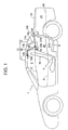
- Figures 1 is a side view of a vehicle with a roof storage structure in accordance with an embodiment of the present invention in which a folding hard roof is in a closed position;
- Figure 2 is a side view of the vehicle in which the folding hard roof is on the way to a roof storage space;
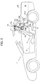
- Figure 3 is a side view of the vehicle in a two-seater open mode in which the folding hard roof is retracted;
- Figures 4 is a side view of the vehicle with an upper seatback of a rear seatback of a rear seat is laid forward down and then slid backward in a trunk room so as thereby to make a passenger compartment open into the trunk room;
- Figure 5 is a perspective view of a rear seat section of the vehicle in which the upper seatback of the rear seatback of one of two rear seats is laid forward down;
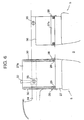
- Figure 6 is a front view of the upper seatback of the rear seatback;
- Figure 7 is a side view of the upper seatback of the rear seatback;
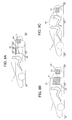
- Figure 8A is a schematic side view of the vehicle in the two-seater open mode;
- Figure 8B is a schematic side view of the vehicle in a closed utility mode;
- Figure 8C is a schematic side view of the vehicle in an ordinary four-seat mode;
- Figures 9 is a side view of a vehicle with a roof storage structure in accordance with another embodiment of the present invention in which an upper seatback of a folding rear seatback of a rear seat is folded and laid down so as thereby to make a passenger compartment open into a trunk room;
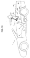
- Figures 10 is a side view of the vehicle of the other embodiment in which the folding hard roof is on the way to a roof storage space;
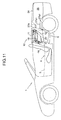
- Figures 11 is a side view of the vehicle of the other embodiment in a two-seater open mode in which the folding hard roof is retracted;
- Figures 12A is a perspective view of the folding rear seatback;
- Figures 12B is a perspective view showing one example of the folding rear seatback; and
- Figures 12C is a perspective view showing another example of the folding rear seatback.
-
- In the following description, the same reference numerals are used to denote elements and/or mechanisms that are the same as or similar in operation and structure throughout the drawings. A folding hard roof is shown as one example of folding roofs that can be retracted in a roof storage structure of the present invention and not confined in roof structure and folding structure to the shown example.
- Referring to the drawings in detail, and, more particularly, to Figures 1 through 3 showing a
vehicle 1 with a foldinghard roof 10 such as a two-door sports vehicle, thevehicle 1 is equipped withside doors 15 and has apassenger compartment 2 opened and closed by theside doors 15. There are equipped with four seats, namely twofront bucket seats 4 and tworear seats 5 such as auxiliary rumble seats simplified in structure, in thepassenger compartment 2. Thepassenger compartment 2 at its floor has a comparativelyhigh floor tunnel 3 formed in the middle of thecompartment 2 in a transverse direction of thevehicle 1 and extending in a lengthwise direction of thevehicle 1 from the front to the back. Thefront seats 4 are disposed on opposite lateral sides of thefloor tunnel 3, respectively. Similarly, therear seats 5 are disposed on opposite lateral sides of thefloor tunnel 3, respectively. Therear seat 5 comprises arear seat cushion 5c and arear seatback 27. Therear seatback 27 comprises two halves of seatbacks, namely an upper half of seatback (which is hereafter referred to as an upper seatback) 27a extending above thefloor tunnel 3 and a lower half of seatback (which is hereafter referred to as a stationary lower seatback) 27b extending below thefloor tunnel 3. Theseat cushion 5c and the stationarylower seatback 27b are formed as an integral piece. Theupper seatback 27a is pivotally mounted to part of the vehicle body so as to turn forward and slide horizontally backward after turning forward as will be described in detail later. - The folding
hard roof 10 is divided into three separate roof sections or components namely afront roof component 11, amiddle roof component 12 and arear roof component 13. Thefront roof component 11 is made of a comparatively light rigid panel, desirably such as for example an aluminum panel, which has a flat square shape so as to cover over a space above heads of passengers sitting on thefront seats 5. Themiddle roof component 12 is made of a comparatively light rigid panel, desirably such as for example an aluminum panel, which has a shape comprising an approximately flattop part 12b andopposite side parts 12a extending between the flattop part 12b and rear side body panels of thevehicle 1 behind theside doors 15, respectively. Therear roof component 13, that is formed by means of arear window glass 13a fitted in a desirably single piece ofwindow frame 13b having afront frame portion 13c and ahemline frame portion 13d, extends obliquely downward from a rear top edge of the flattop part 12b of themiddle roof component 12 and curves convexly rearward between rear edges of theopposite side parts 12a of themiddle roof component 12. Thefront frame portion 13c and ahemline frame portion 13d forms an obtuse angle therebetween. - The folding
hard roof 10 thus comprising the three roof components is equipped with a folding structure comprising two folding link mechanisms arranged disposed at opposite sides of the foldinghard roof 10, respectively. Specifically, each of the folding link mechanism comprises apivot shaft 16 that is fixedly attached to the rear side body panel on which themiddle roof component 12 at its lower front end is pivotally mounted, afirst link 17 that is pivotally mounted on apivot shaft 17a fixedly attached to a rear end portion of thefront roof component 11 at one end thereof and apivot shaft 17b fixedly attached to a front end portion of themiddle roof component 12 at another end thereof so as to interconnect thefront roof component 11 and themiddle roof component 12, and amulti-joint link 18 that is pivotally mounted on apivot shaft 18a fixedly attached to the rear end portion of thefront roof component 11 and apivot shaft 17b fixedly attached to a front end portion of themiddle roof component 12 so as to interconnect thefront roof component 11 and themiddle roof component 12. The folding link mechanism further another multi-joint link (not shown) that interconnecting a lower end portion of therear roof component 13 and a lower end portion of themiddle roof component 12. - As shown in Figure 2, when the
middle roof component 12 pivotally turns backward in a clockwise direction about thepivot shaft 16, the folding link mechanism causes thefront roof component 11 to shift approximately horizontally backward and simultaneously causes therear roof component 13 to raise itself upward while shifting forward. As themiddle roof component 12 further pivotally turns backward in the clockwise direction about thepivot shaft 16 until it comes down into an almost recumbent position, therear roof component 13 turns approximately 90° and is finally brought into a position where it places itsfront frame portion 13c in an approximately horizontal position or places thehemline frame portion 13d in an approximately erect position so as to run fronting backsides ofseatbacks 4a of thefront seats 4 that inclines backward as shown in Figure 3. - As apparent from Figure 3 showing the folding
hard roof 10 retracted in arear space 20 of thepassenger compartment 2 between the front andrear seats hard roof 10 is retracted into the rear space, i.e. theroof storage space 20, therear roof component 13 is situated with thehemline frame portion 13d turned approximately 90° into an approximately erect position so as to run fronting backsides ofseatbacks 4a of thefront seats 4, themiddle roof component 12 is turned approximately 90° forward down into a laid position, and thefront roof component 11 is situated in a horizontal position above therear seat 4 so as to cover the middle andrear roof components vehicle 1 with the foldinghard roof 10 retracted in theroof storage space 20 has an external conformation like a two-seater roadstar as shown in Figure 3. - The
vehicle 1 at its rear end has atrunk room 25 that has atrunk room floor 26 and is covered by a trunk rid 24. Thetrunk room floor 26 is level with a top surface of thefloor tunnel 3 of the floor of thepassenger compartment 2 and supports theupper seatback 27a thereon when theupper seatback 27a slides horizontally backward after laying forward down. On the other hand, when theupper seatback 27a lays forward down, there is provided anaperture 36 between thepassenger room 2, in particular therear passenger space 20 of thepassenger room 2, and thetrunk room 25 so as thereby to provide a trunk-through formation which is referred to a state where thepassenger compartment 2 opens into thetrunk room 25 as shown in Figure 4. - Referring to Figures 5 through 7, the
upper seatback 27a at its lower end of each of therear seats 5 disposed on opposite sides of thefloor tunnel 3 is pivotally mounted to thetrunk room floor 26 by a pair ofhinges 28 so as to lay forward down. Thehinge 28 is provided with aroller 29 that rotates about a pivotal axis of thehinge 28 and is received in a guide slot of aguide rail 30 secured to a side surface of theupper seatback 27a so as to slide in the guide slot of theguide rail 30. There is provided a seatback latch mechanism for releasably holding therear seatback 27 in an erect position where theupper seatback 27a extends straight up from the stationarylower seatback 27b. The seatback latch mechanism comprises alatch lever 32 installed in theupper seatback 27a so as to slide up and down, aretainer 33 secured to the back of theupper seatback 27a and astriker 35 secured to arear suspension tower 34 for a rear wheel. While theupper seatback 27a is in the erected position, theretainer 33 is brought into engagement with thestriker 35 and thelatch lever 32 keeps engagement of theretainer 33 with thestriker 35. When thelatch lever 32 is pulled up, it releases the engagement of theretainer 33 with thestriker 35 so as thereby to allow theupper seatback 27a to lay forward down into the horizontal position as shown by an arrow A in Figures 5 and 7. Theupper seatback 27a in the horizontal laid position can be moved backward out of therear space 20 of thepassenger compartment 2 and into thetrunk room 26 as shown by an arrow B in Figures 5 and 7. Theupper seatback 27 can be returned to the erect position in a reverse way. - As apparent from Figure 6 showing the left
rear seat 5 with theupper seatback 27a moved into thetrunk room 26, there is provided the trunk-through formation as shown in Figure 4, thevehicle 1 can be loaded with even an article that is too long to be stored within thetrunk room 26 over therear space 20 and thetrunk room 26. In addition, thevehicle 1 can be loaded with even a bulky article that is too big to be received within thetrunk room 26 in therear space 20. - Figures 8A, 8B and 8C schematically show the
vehicle 1 in different modes of usage. As apparent, thevehicle 1 with the foldinghard roof 10 retracted in theroof storage space 20 can be used as an two-seater open vehicle (which is referred to as a two-seater open mode I) as shown in Figure 8A. Otherwise, thevehicle 1 with the foldinghard roof 10 in a raised operative position is used as a two-door coupe (which is referred to as a closed mode II or III). The vehicle in the closed mode can be changed between two different modes, namely an utility mode II in which theupper seatback 27a of at least one of therear seats 5 is laid forward down and then moved backward into thetrunk room 26 so as thereby to make therear space 20 of thepassenger compartment 2 open into thetrunk room 26 as shown in Figure 8B and an ordinary four-seat mode III in which theupper seatback 27a of therear seats 5 is in the erect position as shown in Figure 8C. In the two-seater open mode I in which theupper seatback 27a of therear seats 5 are laid forward down and then moved into thetrunk room 26, thevehicle 1 provides theroof storage space 20 in which the foldinghard roof 10 is compactly retracted. In the utility mode II in which theupper seatback 27a of at least one of therear seats 5 is laid forward down and then moved into thetrunk room 26 so as thereby to make therear space 20 open into thetrunk room 26, thevehicle 1 expands a utilizable space for cargos L space. In consequence, thevehicle 1 can be loaded with even an article La that is too long to be stored within thetrunk room 26 over therear space 20 and thetrunk room 26. In addition, thevehicle 1 can be loaded with even an article Lb that is too bulky to be received within thetrunk room 26 in therear space 20 in addition to articles in thetrunk room 26. - According to the foregoing description, since the
upper seatbacks 27a of therear seats 5 are laid forward down and moved into thetrunk room 26 before retracting the foldinghard roof 10 into theroof storage space 20, therear roof compartment 13 of the foldinghard roof 10 is prevented from mechanically interfering with theupper seatbacks 27a of therear seats 5 when the foldinghard roof 10 is retracted. In particular, theroof storage space 20 has a width elongated in the lengthwise direction that is provided above thefloor tunnel 3 by laying down theupper seatbacks 27a, so as to receive themiddle roof component 12 that is comparatively bulky as compared with the remaining roof components. - Figures 9 through 12 show a
vehicle 1 with a foldinghard roof 10 that is suitably retracted in a roof storage structure in accordance with another embodiment of the present invention. Thevehicle 1 shown in Figures 9 through 11 is just the same in structure and operation as that of the previous embodiment shown in Figures 2 through 4, except that a twofoldupper seatback 27a is employed. - The twofold
upper seatback 27a of arear seatback 27 of arear seat 5 extends above afloor tunnel 3 and is made up of two mating upper seatback sections, namely an upper seatback section 27a1 and a lower seatback section 27a2. The upper seatback section 27a1 is pivotally mounted to the top of the lower seatback section 27a2 so as to turn approximately 180° forward down against the lower seatback section 27a1. On the other hand, the lower seatback section 27a1 is pivotally mounted on thetrunk room floor 26 of atrunk room 25 so as to turn approximately 90°situate backward and to be situated in a horizontal position in thetrunk room 25. - Figure 12A shows the twofold
upper seatback 27a in detail. As shown, the twofoldupper seatback 27a comprises a generally rectangulartwofold frame 30 and aflexible back sheet 31 such as a net sheet or a fabric which is stretched on thetwofold frame 30. Thetwofold frame 30 comprises apipe frame 30 made up of two mating frame halves, namely an upper frame half 30a1 for the upper seatback section 27a1 and a lower frame half 30a2 for the lower seatback section 27a2. The twofoldupper seatback 27a may be of a folding type or a telescopic type. - Specifically as shown in Figure 12B, a folding type of the twofold upper seat back 27a comprises a generally rectangular
twofold frame 30 that is made up of a generally U-shaped upper frame half 30a1 on which aflexible back sheet 31 is stretched and a generally U-shaped lower frame half 30a2 on which aflexible back sheet 31 is stretched. These upper and lower frame halves 30a1 and 30a2 are connected byhinges 32 so that the upper frame half 30a1 turns 180° forward down against the lower frame half 30a2. - As shown in Figure 12C, a telescopic type of the twofold
upper seatback 27a comprises a generally rectangulartwofold pipe frame 30 on which anelastic back sheet 31 is stretched between upper and lower crossbars. Thetwofold frame 30 is made up of an upper frame half 30a1 comprising a generally U-shaped pipe and a lower frame half 30a2 comprising a generally U-shaped pipe that are telescopically coupled together. When retracting the upper frame half 30a1 into the lower frame half 30a2, the twofoldupper seatback 27a is shortened approximately half in vertical length. In the shortened position of the twofoldupper seatback 27a, theelastic back sheet 31 may be somewhat loosen.
Claims (11)
- A roof storage structure for a four-seat vehicle (1) with a folding hard roof (10) that closes and opening a passenger compartment (2), a front seat (4), a rear seat (5) having a rear seatback (27, 27a, 27b) at least partly movable backward, and a roof storage space (20) formed in said passenger compartment (2) for receiving said folding hard roof (10) retracted therein,
characterized in that;
said roof storage space is provided in a rear passenger space (20) between said front seat (4) and said rear seat (5) that is expanded in a lengthwise direction of said passenger compartment (2) from the front to the back by moving said rear seatback (27a) backward. - A roof storage structure as defined in claim 1, characterized in that said folding hard roof (10) comprises front, middle and rear roof parts (11, 12, 13) mechanically connected with one another and is retracted with said middle and rear roof parts (12, 13) superposed on each other below said front roof part (11) situated horizontally in said roof storage space (20).
- A roof storage structure as defined in claim 1 or 2, characterized in that said rear roof part (13) doubles as a rear windshield (13a).
- A roof storage structure as defined in any one of the preceding claims 1 through 3, characterized in that said rear seat (5) comprises a seat cushion (5c) and a rear setback (27, 27a, 27b) extending upward from said seat cushion (5c), said seatback (27a) being at least partly movable backward with respect to said rear passenger space (20).
- A roof storage structure as defined in any one of the preceding claims 1 through 4, characterized in that said rear seat (5) comprises a seat cushion (5c) and a rear setback (27, 27a, 27b) extending upward from said seat cushion (5c) and comprising a stationary lower seatback part (27b) and an upper seatback part (27a) capable of turning forward down into a horizontal position and then moving backward with respect to said lower seatback part (27b) so as to expand said rear passenger space (20) in said lengthwise direction of said passenger compartment (2).
- A roof storage structure as defined in claim 5, characterized in that said upper seatback part (27a) comprises a lower seatback half (27a1) pivotally connected to said stationary lower seatback part (27b) and an upper seatback half (27a2) movably connected to said lower seatback half (27a1) so that said lower seatback half (27a1) is turned backward down into a horizontal position after superposing said upper seatback half (27a2) on said lower seatback half (27a1), thereby expanding said rear passenger space (20) in said lengthwise direction of said passenger compartment (2).
- A roof storage structure as defined in claim 5, characterized in that said upper seatback part (27a) is of a telescopic type comprising a lower seatback half (27a1) pivotally connected to said stationary lower seatback part (27b) and an upper seatback half (27a2) retractably connected to said lower seatback half (27a1) so that said lower seatback half (27a1) is turned backward down into a horizontal position after retracting said upper seatback half (27a2) into said lower seatback half (27a1), thereby expanding said rear passenger space (20) in said lengthwise direction of said passenger compartment (2).
- A roof storage structure as defined in claim 5, further characterized by seatback latch means (35) for releasably holding said upper seatback part (27a) in a position where said upper seatback part (27a) extends straight up from said stationary lower seatback part (27b).
- A roof storage structure as defined in any one of the preceding claims 1 through 8, characterized in that said vehicle (1) is provided with a trunk room (25) behind said passenger compartment (2) and said rear seat (5) is at least partly movable backward into said trunk room (25).
- A roof storage structure as defined in claim 9, characterized in that said trunk room (25) is spatially separated from said passenger compartment (2) by said rear seat (5) and is made open into said passenger compartment (2) when said rear seat (5) is at least partly moved into said trunk room (25).
- A roof storage structure as defined in any one of the preceding claims 1 through 10, characterized in that said rear seat (5) comprises a seat cushion (5c) and a seatback (27, 27a, 27b) partly integral with said seat cushion (5c) and partly movable with respect to said seat cushion (5c).
Applications Claiming Priority (2)
| Application Number | Priority Date | Filing Date | Title |
|---|---|---|---|
| JP2002047941 | 2002-02-25 | ||
| JP2002047941A JP3885607B2 (en) | 2002-02-25 | 2002-02-25 | Vehicle roof structure |
Publications (2)
| Publication Number | Publication Date |
|---|---|
| EP1338454A1 true EP1338454A1 (en) | 2003-08-27 |
| EP1338454B1 EP1338454B1 (en) | 2006-01-04 |
Family
ID=27655431
Family Applications (1)
| Application Number | Title | Priority Date | Filing Date |
|---|---|---|---|
| EP03002021A Expired - Lifetime EP1338454B1 (en) | 2002-02-25 | 2003-01-28 | Roof storage structure for vehicles |
Country Status (4)
| Country | Link |
|---|---|
| US (1) | US6702363B2 (en) |
| EP (1) | EP1338454B1 (en) |
| JP (1) | JP3885607B2 (en) |
| DE (1) | DE60303054T2 (en) |
Cited By (7)
| Publication number | Priority date | Publication date | Assignee | Title |
|---|---|---|---|---|
| DE102004046482A1 (en) * | 2004-09-23 | 2006-04-06 | Cts Fahrzeug-Dachsysteme Gmbh | Hardtop vehicle roof has at least one roof part that forms an at least approximately horizontal roof box cover when in closed position that at least partly closes roof box |
| GB2420533A (en) * | 2004-11-26 | 2006-05-31 | Ford Global Tech Llc | Motor vehicle with reconfigurable roof |
| WO2007000571A1 (en) * | 2005-06-29 | 2007-01-04 | Ford Global Technologies, Llc | A motor vehicle having a stowable roof |
| EP1741589A1 (en) * | 2005-06-09 | 2007-01-10 | Peugeot Citroën Automobiles S.A. | Vehicle with a foldable rear structure |
| DE102006000966A1 (en) * | 2006-01-07 | 2007-07-26 | Leonie Wörz | Foldable roof structure for covering passenger compartment of motor vehicle, has multiple rigid roof elements, where opening of receptacle is covered by roof structure, which is in unfolded condition |
| GB2436089A (en) * | 2006-03-16 | 2007-09-19 | Ford Global Tech Llc | A motor vehicle with a folding roof |
| EP1897716A3 (en) * | 2006-09-08 | 2012-11-07 | Dr. Ing. h.c. F. Porsche AG | Flexible vehicle roof |
Families Citing this family (24)
| Publication number | Priority date | Publication date | Assignee | Title |
|---|---|---|---|---|
| FR2828137B1 (en) * | 2001-08-01 | 2004-03-26 | France Design | RIGID RETRACTABLE ROOF SYSTEM FOR MOTOR VEHICLE |
| US6866324B2 (en) * | 2002-02-25 | 2005-03-15 | Ssr Roofing Systems, L.L.C. | Folding hardtop with rear window articulation |
| US6938949B1 (en) * | 2004-03-08 | 2005-09-06 | General Motors Corporation | Open-air pickup truck |
| DE102004028467A1 (en) | 2004-06-11 | 2005-12-29 | Wilhelm Karmann Gmbh | Convertible car |
| US20090146461A1 (en) * | 2005-01-09 | 2009-06-11 | Webasto Ag | Motor vehicle equipped with a roof that can be opened |
| US7229122B2 (en) * | 2005-07-19 | 2007-06-12 | Martin Jay R | Motor assisted movement of vehicle top with storage area lid |
| US7226109B2 (en) * | 2005-07-19 | 2007-06-05 | Martin Jay R | Movement of vehicle top over recessed accessible storage area lid and method to preserve vehicle profile |
| US7520556B2 (en) * | 2005-07-19 | 2009-04-21 | Jay Martin | Retractable vehicle roof system with storage area lid |
| DE102005041220A1 (en) * | 2005-08-31 | 2007-03-01 | Daimlerchrysler Ag | Retractable folding top for open-top car e.g. roadster, has main handle bars supported in associated console of car structure by main bearings, where one of bearings is movably formed opposite to console and/or to main handle bar |
| DE102005049339B4 (en) * | 2005-10-12 | 2007-11-08 | Magna Car Top Systems Gmbh | Vehicle with hardtop roof |
| US20070096500A1 (en) * | 2005-10-28 | 2007-05-03 | Corder George A | Hard top convertible roof |
| JP4766386B2 (en) * | 2006-03-27 | 2011-09-07 | スズキ株式会社 | Rear structure of roof-open vehicle |
| JP4766387B2 (en) * | 2006-03-27 | 2011-09-07 | スズキ株式会社 | Automobile roof structure |
| JP5047522B2 (en) | 2006-03-28 | 2012-10-10 | ベバスト ジャパン株式会社 | Retractable roof and vehicle equipped with the same |
| JP2007261407A (en) | 2006-03-28 | 2007-10-11 | Webasto Japan Kk | Retractable roof, and vehicle provided with the same |
| DE102006042203A1 (en) * | 2006-09-08 | 2008-03-27 | Dr.Ing.H.C. F. Porsche Ag | vehicle roof |
| JP4978168B2 (en) * | 2006-11-24 | 2012-07-18 | トヨタ自動車株式会社 | Open car windbreak device |
| JP4306735B2 (en) * | 2007-01-31 | 2009-08-05 | トヨタ自動車株式会社 | Vehicle seat |
| US7866726B2 (en) * | 2007-12-21 | 2011-01-11 | Wilhelm Karmann Gmbh | Convertible top having movable outboard panels |
| JP5625784B2 (en) * | 2010-11-15 | 2014-11-19 | マツダ株式会社 | Open roof structure of vehicle |
| DE102011000435B4 (en) * | 2011-02-01 | 2022-10-06 | Dr. Ing. H.C. F. Porsche Aktiengesellschaft | Cabriolet with a roof assembly |
| US8746772B2 (en) * | 2011-12-20 | 2014-06-10 | Honda Motor Co., Ltd. | Seating assembly for a vehicle |
| DE102012018923A1 (en) * | 2012-09-25 | 2014-03-27 | Audi Ag | Vehicle e.g. motor car has roof portion in rear chamber, which is detachably connected to backrest in receiving position by receiving device, and is movable together with trunk tray into the storage position |
| US10029548B1 (en) * | 2015-10-07 | 2018-07-24 | Mark A. Stadnyk | Adjustable and removable hard top roof system |
Citations (4)
| Publication number | Priority date | Publication date | Assignee | Title |
|---|---|---|---|---|
| FR2351819A1 (en) * | 1976-05-20 | 1977-12-16 | Renault | REAR BENCH WITH REMOVABLE BACKREST FOR MOTOR VEHICLES |
| US4796943A (en) * | 1985-11-20 | 1989-01-10 | Mazda Motor Corporation | Convertible vehicle body structure having a rear seat |
| US5429409A (en) * | 1993-01-04 | 1995-07-04 | Asc Incorporated | Convertible top |
| DE4438190C1 (en) * | 1994-08-01 | 1995-11-30 | Daimler Benz Ag | Two-shell folding roof for convertible motor vehicle |
Family Cites Families (25)
| Publication number | Priority date | Publication date | Assignee | Title |
|---|---|---|---|---|
| FR2589800B1 (en) * | 1985-11-08 | 1989-06-23 | Peugeot Cycles | TRANSFORMABLE REAR SEAT |
| JPH0628973B2 (en) * | 1985-11-20 | 1994-04-20 | マツダ株式会社 | Car roof structure |
| JPH06465B2 (en) * | 1985-11-20 | 1994-01-05 | マツダ株式会社 | Car roof structure |
| DE3639376A1 (en) * | 1985-11-20 | 1987-05-27 | Mazda Motor | ROOF CONSTRUCTION FOR A VEHICLE BODY WITH A FOLDING CANOPY |
| US4758038A (en) * | 1986-03-17 | 1988-07-19 | Mazda Motor Corporation | Upper body structure of vehicle |
| JPS6390432A (en) * | 1986-10-02 | 1988-04-21 | Mazda Motor Corp | Structure of upper car body of automobile |
| DE4438191C1 (en) * | 1994-07-08 | 1995-07-13 | Daimler Benz Ag | Open vehicle with roof lowerable into storage space |
| IT1278123B1 (en) * | 1994-07-08 | 1997-11-17 | Daimler Benz Ag | VEHICLE WITH ROOF AT LEAST PARTIALLY LOWERING. |
| JPH0858387A (en) * | 1994-08-26 | 1996-03-05 | Kanto Auto Works Ltd | Open car hood storage structure |
| DE4430672C1 (en) * | 1994-08-29 | 1995-12-14 | Robin Bennett | Wind protection device for convertible vehicle |
| DE4431573A1 (en) * | 1994-09-05 | 1995-03-30 | Gian Hung Chang | Vehicle seat |
| DE4431656C1 (en) * | 1994-09-06 | 1995-12-07 | Daimler Benz Ag | Stowage space arrangement for folding roof of motor car |
| DE19514785C2 (en) * | 1995-04-21 | 1998-07-02 | Audi Ag | Vehicle with storage space for a folding roof |
| DE19546083C2 (en) * | 1995-12-11 | 1997-10-23 | Daimler Benz Ag | Cabriolet with two front seats and a rear seat area |
| DE19635536C1 (en) * | 1996-09-02 | 1998-01-22 | Daimler Benz Ag | Movable roof-structure for convertible car |
| DE19706398A1 (en) * | 1997-02-19 | 1998-08-20 | Daimler Benz Ag | Hard top for a convertible |
| JPH11342793A (en) * | 1998-06-04 | 1999-12-14 | Honda Motor Co Ltd | Cabin closed structure for automobiles |
| DE29817132U1 (en) * | 1998-09-24 | 2000-02-10 | Edscha Cabrio-Verdecksysteme GmbH & Co., 94491 Hengersberg | With a convertible vehicle that can be moved into an open position |
| FI111149B (en) * | 1999-03-03 | 2003-06-13 | Valmet Automotive Oy | Openable roof mechanism for open car, system to prevent the car from overturning, and a convertible |
| US6481772B1 (en) * | 1999-10-15 | 2002-11-19 | Subaru Of America, Inc. | Vehicle having a foldable seat with a retractable window and an extending cargo bed |
| DE10025051C1 (en) * | 2000-05-23 | 2001-11-15 | Webasto Vehicle Sys Int Gmbh | Car has sunshine roof which extends across its whole width and slides back on to rear window both components then sliding back over boot |
| DE10104523C2 (en) * | 2001-01-31 | 2003-05-22 | Webasto Vehicle Sys Int Gmbh | Openable vehicle roof and method for operating the same |
| US6666495B2 (en) * | 2001-09-13 | 2003-12-23 | Edscha Roof Systems Inc. | Retractable top system for vehicles with movable rear section |
| DE10152944B4 (en) * | 2001-10-26 | 2016-12-15 | Webasto-Edscha Cabrio GmbH | Hood for a convertible vehicle |
| US6598926B1 (en) * | 2002-10-09 | 2003-07-29 | General Motors Corporation | Transformable rear seat for a vehicle |
-
2002
- 2002-02-25 JP JP2002047941A patent/JP3885607B2/en not_active Expired - Fee Related
-
2003
- 2003-01-28 DE DE60303054T patent/DE60303054T2/en not_active Expired - Lifetime
- 2003-01-28 EP EP03002021A patent/EP1338454B1/en not_active Expired - Lifetime
- 2003-02-20 US US10/368,454 patent/US6702363B2/en not_active Expired - Fee Related
Patent Citations (4)
| Publication number | Priority date | Publication date | Assignee | Title |
|---|---|---|---|---|
| FR2351819A1 (en) * | 1976-05-20 | 1977-12-16 | Renault | REAR BENCH WITH REMOVABLE BACKREST FOR MOTOR VEHICLES |
| US4796943A (en) * | 1985-11-20 | 1989-01-10 | Mazda Motor Corporation | Convertible vehicle body structure having a rear seat |
| US5429409A (en) * | 1993-01-04 | 1995-07-04 | Asc Incorporated | Convertible top |
| DE4438190C1 (en) * | 1994-08-01 | 1995-11-30 | Daimler Benz Ag | Two-shell folding roof for convertible motor vehicle |
Cited By (16)
| Publication number | Priority date | Publication date | Assignee | Title |
|---|---|---|---|---|
| DE102004046482A1 (en) * | 2004-09-23 | 2006-04-06 | Cts Fahrzeug-Dachsysteme Gmbh | Hardtop vehicle roof has at least one roof part that forms an at least approximately horizontal roof box cover when in closed position that at least partly closes roof box |
| DE102004046482B4 (en) * | 2004-09-23 | 2009-03-19 | Magna Car Top Systems Gmbh | Hardtop vehicle roof with at least one roof part |
| GB2420533B (en) * | 2004-11-26 | 2008-07-09 | Ford Global Tech Llc | A motor vehicle |
| GB2420533A (en) * | 2004-11-26 | 2006-05-31 | Ford Global Tech Llc | Motor vehicle with reconfigurable roof |
| DE102005056714B4 (en) * | 2004-11-26 | 2009-11-26 | Ford Global Technologies, LLC, Dearborn | Motor vehicle and method for converting a motor vehicle |
| EP1741589A1 (en) * | 2005-06-09 | 2007-01-10 | Peugeot Citroën Automobiles S.A. | Vehicle with a foldable rear structure |
| US7815240B2 (en) | 2005-06-29 | 2010-10-19 | Ford Global Technologies, Llc | Motor vehicle having a stowable roof |
| GB2440889A (en) * | 2005-06-29 | 2008-02-13 | Ford Global Tech Llc | A Motor vehicle having a stowable roof |
| GB2440889B (en) * | 2005-06-29 | 2009-01-07 | Ford Global Tech Llc | A Motor vehicle having a stowable roof |
| WO2007000571A1 (en) * | 2005-06-29 | 2007-01-04 | Ford Global Technologies, Llc | A motor vehicle having a stowable roof |
| DE102006000966A1 (en) * | 2006-01-07 | 2007-07-26 | Leonie Wörz | Foldable roof structure for covering passenger compartment of motor vehicle, has multiple rigid roof elements, where opening of receptacle is covered by roof structure, which is in unfolded condition |
| WO2007105013A1 (en) * | 2006-03-16 | 2007-09-20 | Ford Global Technologies, Llc | A motor vehicle |
| GB2436089A (en) * | 2006-03-16 | 2007-09-19 | Ford Global Tech Llc | A motor vehicle with a folding roof |
| CN101360624B (en) * | 2006-03-16 | 2010-11-03 | 福特全球技术公司 | A motor vehicle |
| US8002327B2 (en) | 2006-03-16 | 2011-08-23 | Ford Global Technologies | Motor vehicle |
| EP1897716A3 (en) * | 2006-09-08 | 2012-11-07 | Dr. Ing. h.c. F. Porsche AG | Flexible vehicle roof |
Also Published As
| Publication number | Publication date |
|---|---|
| EP1338454B1 (en) | 2006-01-04 |
| DE60303054D1 (en) | 2006-03-30 |
| US6702363B2 (en) | 2004-03-09 |
| US20030160475A1 (en) | 2003-08-28 |
| JP2003246222A (en) | 2003-09-02 |
| DE60303054T2 (en) | 2006-08-31 |
| JP3885607B2 (en) | 2007-02-21 |
Similar Documents
| Publication | Publication Date | Title |
|---|---|---|
| EP1338454B1 (en) | Roof storage structure for vehicles | |
| US5769483A (en) | Convertible motor vehicle roof | |
| US8136857B2 (en) | Pick-up style utility vehicle with expandable cargo bed | |
| US6062625A (en) | Variable roof box for a convertible | |
| US8414049B2 (en) | Vehicle cargo system with multi-function tonneau cover | |
| US8328262B2 (en) | Pick-up style utility vehicle with expandable cargo bed | |
| US6595522B2 (en) | Vehicle seat covering system | |
| US20020105206A1 (en) | Folding top rear quarter window storage system | |
| JP3524524B2 (en) | Convertible hardtop storage structure | |
| US7909382B2 (en) | Automobile | |
| US8128144B2 (en) | Pick-up style utility vehicle with expandable cargo bed | |
| US7063371B2 (en) | Convertible hardtop roof | |
| US20040145212A1 (en) | Retractable hard top with inboard connections | |
| US7017972B2 (en) | Motor vehicle which can be converted from a pick-up into a convertible | |
| US6722724B1 (en) | Four section retractable hard top | |
| EP1549519B1 (en) | Decklid mechanism for vehicle with retractable top | |
| US20050017548A1 (en) | Motor vehicle which can be converted from a pick-up into a convertible | |
| US20040212213A1 (en) | Convertible vehicle with a retractable roof | |
| US7815253B2 (en) | Storage structure for a cover member of a sliding roof type vehicle and a vehicle provided with the same | |
| US8002327B2 (en) | Motor vehicle | |
| JP3992897B2 (en) | Underfloor storage seat structure | |
| US7686377B2 (en) | Convertible with a roof which can be stored below a covering | |
| JP3632737B2 (en) | Rear body structure of the vehicle | |
| EP1323562A1 (en) | Trunk lid arrangement | |
| JP2003118451A (en) | Vehicle seat |
Legal Events
| Date | Code | Title | Description |
|---|---|---|---|
| PUAI | Public reference made under article 153(3) epc to a published international application that has entered the european phase |
Free format text: ORIGINAL CODE: 0009012 |
|
| AK | Designated contracting states |
Designated state(s): AT BE BG CH CY CZ DE DK EE ES FI FR GB GR HU IE IT LI LU MC NL PT SE SI SK TR |
|
| AX | Request for extension of the european patent |
Extension state: AL LT LV MK RO |
|
| 17P | Request for examination filed |
Effective date: 20040108 |
|
| 17Q | First examination report despatched |
Effective date: 20040303 |
|
| AKX | Designation fees paid |
Designated state(s): DE |
|
| GRAP | Despatch of communication of intention to grant a patent |
Free format text: ORIGINAL CODE: EPIDOSNIGR1 |
|
| GRAS | Grant fee paid |
Free format text: ORIGINAL CODE: EPIDOSNIGR3 |
|
| GRAA | (expected) grant |
Free format text: ORIGINAL CODE: 0009210 |
|
| AK | Designated contracting states |
Kind code of ref document: B1 Designated state(s): DE |
|
| REF | Corresponds to: |
Ref document number: 60303054 Country of ref document: DE Date of ref document: 20060330 Kind code of ref document: P |
|
| PLBE | No opposition filed within time limit |
Free format text: ORIGINAL CODE: 0009261 |
|
| STAA | Information on the status of an ep patent application or granted ep patent |
Free format text: STATUS: NO OPPOSITION FILED WITHIN TIME LIMIT |
|
| 26N | No opposition filed |
Effective date: 20061005 |
|
| PGFP | Annual fee paid to national office [announced via postgrant information from national office to epo] |
Ref country code: DE Payment date: 20110126 Year of fee payment: 9 |
|
| PG25 | Lapsed in a contracting state [announced via postgrant information from national office to epo] |
Ref country code: DE Free format text: LAPSE BECAUSE OF NON-PAYMENT OF DUE FEES Effective date: 20120801 |
|
| REG | Reference to a national code |
Ref country code: DE Ref legal event code: R119 Ref document number: 60303054 Country of ref document: DE Effective date: 20120801 |