Technical Field
-
The present invention relates to a filter apparatus and
particularly to an immersion type membrane filter apparatus,
which is kept immersed in a fluid to be processed, for obtaining
filtrate by filtrating the fluid to be processed.
Background Art
-
Recently, immersion type membrane filtration methods
have been utilized in a variety of fields, the methods involving
immersing a membrane module in a fluid to be processed and
filtrating the fluid to be processed that is caused to be
naturally circulating by taking advantage of the buoyancy of
air bubbles (for example, refer to Japanese Patent Laid-Open
No. 61-129094). The method is an energy conservation precision
process for filtrating highly contaminated liquids such as an
activated sludge processed fluid in place of an ultrafiltration
method that involves forcibly supplying a fluid to be processed
to a membrane module by mechanical circulating means such as
a pump and circulating.
-
Membrane modules for use in such immersion type membrane
filtration methods are generally called immersion type
filtration membrane modules and are exclusively a hollow fiber
module and a flat sheet module (for example, see "Report on
Commercialization of Small-Size Domestic Wastewater
Processing Apparatus that Introduces a Membrane Processing
Method, 1992 to 1995 Edition," Japan Education Center of
Environmental Sanitation). Here, a hollow fiber module is
fabricated by collecting numerous hollow fiber membranes with
both outside and inside diameters of a few millimeters and
fixing both ends. The module can filtrate a fluid to be
processed by reducing the inside pressure of the hollow fiber
membrane and passing the fluid to be processed from the outside
into the inside thereof. On the other hand, a flat sheet module
comprises a plurality of flat sheet membranes set like a bag.
It can filtrate a fluid to be processed by reducing the inside
pressure of the flat sheet membrane and passing the fluid to
be processed from the outside into the inside thereof.
Incidentally, in a hollow fiber module, why a fluid to be
processed is rendered to pass from the outside to the inside
of the hollow fiber membrane is that, because of the inside
diameter of the hollow fiber membrane being almost the same as
the size of materials to be filtrated and activated sludge,
contained in a fluid to be processed, passage of the fluid to
be processed from the inside to the outside of the hollow fiber
membrane raises the possibility of the hollow fiber membrane
being clogged and closed, and that air bubbles hardly pass
through the inside of the hollow fiber membrane leading to the
difficulty of natural circulation of the fluid to be processed.
On the other hand, in a flat sheet module, passage of a fluid
to be processed from the outside to the inside of the flat sheet
membrane is likely to form, due to air bubbles, an upward-moving
stream of the fluid to be processed required for rendering the
fluid to be processed to naturally circulate.
-
When comparing the hollow fiber membrane with the flat
sheet module, the hollow fiber module has a larger membrane area
per volume than the flat sheet module, and thus can enhance the
volume efficiency. In other words, for a hollow fiber module
and a flat sheet module with the same membrane area, the hollow
fiber module can be made more compactly. In contrast, a flat
sheet module is large in flux (filtration flow rate per unit
area of membrane) as compared with a hollow fiber module, and
therefore it can perform immersion type membrane filtration
more efficiently than the hollow fiber module. Therefore, an
immersion type membrane filter apparatus utilizing these
immersion type filtration membrane modules is substantially
difficult to conduct miniaturization as well as enhancing the
filtration efficiency at the same time.
-
In addition, in these immersion type filtration membrane
modules, the flux is increased with increasing air bubble amount
to be supplied, and so the energy cost for supplying air bubbles
is increased in order to enhance the filtration efficiency by
attaining a specified amount of flux. Also, in the immersion
type membrane filter apparatus using a hollow fiber module, the
increase of the volume of air bubbles to be supplied requires
ease of the air bubbles being passed by setting large the
clearance between hollow fiber membranes, and thus it becomes
difficult to enhance the volume efficiency of the hollow fiber
module.
-
The object of the present invention is to realize an
immersion type membrane filter apparatus being a small size as
well as being capable of economically enhancing the filtration
efficiency.
Disclosure of the Invention
-
An immersion type membrane filter apparatus of the
present invention is an apparatus for obtaining filtrate by
filtrating a fluid to be processed stored in a storage bath.
The apparatus comprises a filtration module and an air bubbles
supply device for supplying air bubbles to the filtration
membrane module. The filtration membrane module includes a
group of tubular membranes containing a plurality of tubular
membranes having on the inner surfaces thereof the function of
filtrating the fluid to be processed. The group of tubular
membranes is disposed within a columnar housing vessel having
a discharge port for the filtrate and is supported by both the
ends of the housing vessel. The filtration membrane module is
capable of being immersed in the fluid to be processed in the
storage bath in such a way that the tubular membranes are opened
in the vertical direction. The air bubbles supply device is
disposed beneath the filtration membrane module within the
storage bath.
-
Here, the discharge port of the housing vessel is placed,
for example, in such a way that the water head pressure of a
fluid to be processed stored in the storage bath is capable of
discharging the filtrate. Alternatively, this immersion type
membrane filter apparatus is, for example, further equipped
with means for setting the pressure of the discharge port at
a negative pressure.
-
The tubular membrane for use in the aforementioned
immersion type membrane filter apparatus is, for example,
provided with a filtration membrane layer formed like a cylinder
and a support membrane layer having liquid permeability for
imparting shape keeping property to the filtration membrane
layer, with the crushing pressure being set at least at 20 kPa.
Here, the filtration membrane layer is, for example, composed
of a microfiltration membrane. This tubular membrane may
further be provided with a reinforcing layer having liquid
permeability disposed on the outer periphery of the support
membrane layer. In this case, the support membrane layer and
the reinforcing layer are preferably formed by using a polyester
resin-based unwoven cloth. The inside diameter of the tubular
membrane is preferably set at from 3 to 15 mm. In addition,
the ratio (A/B) of the wall thickness A to the outside diameter
B of the tubular membrane is preferably set at from 0.025 to
0.1.
-
In addition, the tubular membrane may have a protrusion
having a height of 0.02 to 0.2 mm partially formed on the outer
periphery thereof. In this case, the protrusion is preferably
spirally formed, with the axis of the filtration membrane layer
being the center thereof.
-
Furthermore, the plurality of the tubular membranes may,
for example, form the group of tubular membranes integrally
knitted using a connecting thread in a plane and parallel
configuration.
-
The group of filtration membranes housed in the housing
vessel is normally maintained at both ends of the housing vessel
by means of a resin. In this case, the housing vessel preferably
possesses at least one of a convex portion and a concave portion
on the inner periphery of the both ends.
-
A filtration membrane module for use in an immersion type
membrane filter apparatus of the present invention normally has
spacers for creating clearances between the discharge port and
the group of tubular membranes in the housing vessel.
Preferably, this filtration membrane module normally uses a
tubular membrane having an inside diameter of 3 to 15 mm, and
is set such that the packing rate of tubular membranes expressed
by Equation (I) below is at least 0.7:
Packing rate = Nπd0 2 4S
wherein N is the number of tubular membranes contained in the
group of tubular membranes, d0 is the outside diameter of the
tubular membrane, and S is the cross-sectional area of the
inside, perpendicular to the axial direction, of the housing
vessel.
-
Additionally, the above-mentioned spacer is normally
preferably set in such a way that the ratio of the portion area
of the spacer to the cross-sectional area of the inside equipped
with the spacer, perpendicular to the axial direction, of the
housing vessel is from 3 to 10%.
-
Also, in a filtration membrane module for use in an
immersion type membrane filter apparatus of the present
invention, the housing vessel may be provided with a columnar
water-collecting tube having fluid-passing holes and an outer
column disposed with space on the outer peripheral of the
water-collecting tube, with the group of tubular membrane being
disposed between the water-collecting tube and the outer column,
the water-collecting tube having the aforementioned discharge
port. Preferably, such a filtration membrane module uses a
tubular membrane having an inside diameter of 3 to 15 mm and
is fabricated so that the ratio ( ds /S1 ) of the outside diameter
ds of the water-collecting tube to the cross-sectional area S1
perpendicular to the axial direction between the water-collecting
tube and the outer column is set at from 0.3 to 1m-1.
Also, the packing rate of the tubular membranes expressed by
Equation (II) below is preferably set at least at 0.8:
Packing rate = Nπd0 2 4S 1
wherein N is the number of tubular membranes contained in the
group of tubular membranes, and d0 is the outside diameter of
the tubular membrane.
-
In a filtration membrane module of this type, a group of
tubular membranes is normally placed between the water-collecting
tube and the outer column with a distance from the
water-collecting tube. In addition, the water-collecting tube
and the outer column normally have a cylindrical shape.
-
A housing vessel of a filtration membrane module for use
in the aforementioned immersion type membrane filter apparatus
may have a wall portion extending from the end of the air bubbles
supply device side toward the air bubbles supply device.
-
When a fluid to be processed is filtrated by means of the
above-mentioned immersion type membrane filter apparatus
relating to the present invention, the fluid to be processed
stored in the storage bath is passed from the down side toward
the upside through each tubular membrane along with air bubbles
supplied from the air bubbles supply device toward the
filtration membrane module and is naturally circulates in the
storage bath. At this time, part of the fluid to be processed
is passed through the tubular membrane from the inside toward
the outside and components to be filtrated contained in the
fluid to be processed are collected on the inner surfaces of
the tubular membrane having filtration function. In this
manner, the components removed fluid processed (filtrate) is
flowed into the housing vessel and then is discharged at the
discharge port. The filtration membrane module used in this
procedure uses a tubular membrane having filtration function
on the inner surface, and thus has a large membrane area per
volume as compared with conventional modules using a hollow
fiber membrane or a flat sheet membrane. Therefore, the module
is more readily miniaturized than conventional modules. In
addition, immersion type membrane filtration processing by use
of this filtration membrane module provides a larger flow rate
per volume of filtration membrane module than the process where
a hollow fiber module or a flat sheet module is employed, when
the volume of air bubbles to be supplied is set at a level similar
to that where a conventional module is used, on account of
similar reasons. In other words, this filtration membrane
module enables the enhancement of filtration efficiency while
reducing energy required for air bubbles supply. Accordingly,
an immersion type membrane filter apparatus of the present
invention can be miniaturized as compared with a conventional
one, and enables efficient and economical conduct of immersion
type membrane filtration.
-
An immersion type membrane filter apparatus of the
present invention may be provided with a guide column for
guiding air bubbles from the air bubbles supply device toward
the filtration membrane module. The guide column is capable
of disposing a filtration membrane module on the upper portion
thereof, wherein the shape and size of the inner circumference
of the cross section, perpendicular to the axial direction, of
the guide column is set substantially equal to the shape and
size of the inner circumference of the outer circumferential
portion of the cross section, perpendicular to the axial
direction, of the housing vessel.
-
In this case, the air bubbles supply device preferably
has a plurality of air bubbles spouting pores, and the air
bubbles spouting pores may be placed in a configuration pattern
such that the air bubbles at least at 30% of the average value
of the air flow rate per tubular membrane, i.e. the total flow
rate of air bubbles to be supplied to the filtration membrane
module divided by the total number of tubular membranes, can
be distributed to at least half the number of tubular membranes.
-
Alternatively, the air bubbles supply device is
preferably provided with a plain body made of a elastic rubber
body having substantially the same size and shape as the inner
circumferential line of the outer circumferential portion in
the cross section, vertical to the axial direction, of the guide
column and the air supply device for supplying air from the lower
portion relative to the plain body. The plain body preferably
has on the whole face thereof a plurality of air bubbles spouting
pores for spouting air bubbles , the spouting pores being capable
of opening and shutting according to increase and decrease of
the pressure of the air supplied from the air supply device.
In this case, the air bubbles spouting pores of the plain body
are preferably set to be able to spout air bubbles having a
diameter of at least 1/3 of the inside diameter of the tubular
membrane.
-
When an immersion type membrane filter apparatus of the
present invention is equipped with a guide column and an air
bubbles supply device as stated above, air bubbles can uniformly
be supplied to each of tubular membranes of the filtration
membrane module, and thus the filtration flow rate in each
tubular membrane is enhanced, leading to further enhancement
of the filtration efficiency. Accordingly, this immersion
type membrane filter apparatus is more readily miniaturized as
compared with conventional apparatuses and also can conduct
immersion type membrane filtration more efficient and
economical.
-
In particular, when a device equipped with a plain body
made of an elastic rubber body as mentioned above is used as
an air bubbles supply device, the elastic force contracts this
plain body to shut the air bubbles spouting pores, when the
supply of air from the air supply device is stopped, i.e. when
the body does not undergo the pressure of the air from the air
supply device. For this reason, this air bubbles supply device
prevents effectively the blockage of the air bubbles spouting
pores due to contamination components contained in a fluid to
be processed, thereby enabling stably the supply of air bubbles .
-
In addition, an immersion type membrane filter apparatus
of the present invention may further comprise a filling material
bed containing a filling material and disposed between the
filtration membrane module and the air bubbles supply device,
for guiding the air bubbles with dispersion from the air bubbles
supply device toward the filtration membrane module. In this
case, the filling material bed is preferably set to be able to
disperse air bubbles from the air bubbles supply device in such
a way that air bubbles at least at 30% of the average value of
the air flow rate per tubular membrane, i.e. the total flow rate
of air bubbles to be supplied from the air bubbles supply device
divided by the total number of tubular membranes, can be
distributed to at least half the number of tubular membranes.
Furthermore, the filling material used here is normally a porous
hollow cylindrical material having an outside diameter of 5 to
50 mm and a length of 5 to 50 mm. This hollow cylindrical
material is, for example, a microorganism carrier.
-
When an immersion type membrane filter apparatus of the
present invention is provided with a filling material bed as
stated above, air bubbles from the air bubbles supply device
is raised in a fluid to be processed, and then is supplied to
the filtration membrane module subsequent to passing through
the filling material bed. Here, the air bubbles from the air
bubbles supply device are disturbed when passing through the
filling material bed and dispersed, and then can equally be
supplied to each tubular membrane of the filtration membrane
module. As a result, in the filtration membrane module, the
filtration flow rate is increased leading to further
enhancement of the filtration efficiency of the fluid to be
processed. In addition, the filling material bed can disperse
air bubbles from the air bubbles supply device and at the same
time capture a variety of contaminants contained in the fluid
to be processed. Because of this, tubular membranes
constituting the filtration membrane module undergoes the
suppression of blockage due to contaminants and thus enables
stable maintenance of filtration efficiency.
-
Furthermore, when the filling material bed contains as
the filling material porous hollow cylindrical materials as
mentioned above and also the hollow cylindrical materials are
a microorganism carrier, the efficiency of immersion type
membrane filtration processing is maintained even though a
fluid to be processed is microorganism-containing material such
as an activated sludge processed fluid of domestic wastewater.
In other words, in this case, because microorganisms contained
in the fluid to be processed is captured by the hollow
cylindrical material and maintained, the quality of processed
liquid is scarcely lowered even if the fluid to be processed
is abruptly flowed in. For this reason, clogging of the tubular
membrane is suppressed, the efficiency of the immersion type
membrane filter apparatus is maintained.
-
An immersion type membrane filter apparatus of the
present invention may further be provided with a filtrate
discharge pathway extending from the discharge port of the
housing vessel and a backwashing device for flowing the filtrate
in the filtrate discharge pathway backwards while pressurizing
it via the discharge port into the housing vessel. This
backwashing device is equipped with, for example, an air supply
device and pressurizing means for applying the pressure of air
coming from the air supply device to the filtrate within the
filtrate discharge pathway in the discharge port direction. In
this case, the backwashing device is preferably further
provided with a back-flow rate setting device for setting the
amount of filtrate that is caused to flow backwards into the
housing vessel at least at 200 ml per square meter of membrane
area of tubular membranes housed within the housing vessel.
Here, the back-flow rate setting device is, for example, a
quantity float valve. In addition, air from the air supply
device is preferably set so that the air can also be supplied
to the air bubbles supply device.
-
When an immersion type membrane filter apparatus of the
present invention is equipped with a backwashing device as
mentioned above, the tubular membranes are pressurized from the
outside toward the inside by the filtrate flowing backwards
through the discharge port into the housing vessel and are
thereby washed. Namely, in the tubular membranes, filtrated
components deposited on the inner surface thereof, from a fluid
to be processed, is removed by the filtrate. For this reason,
the filtration membrane module can recover filtration
performance and thus can maintain filtration performance.
Therefore, the immersion type membrane filter apparatus in this
case can efficiently perform the filtration processing of a
fluid to be processed over extended periods of time.
-
The immersion type membrane filtration method of the
present invention is a method for obtaining filtrate by
filtrating a fluid to be processed stored in a storage bath.
The method comprises a step of disposing in a storage bath a
filtration membrane module which is provided with a group of
tubular membranes containing a plurality of tubular membranes
having on the inner surfaces thereof the function of filtrating
the fluid to be processed being disposed within a columnar
housing vessel having a discharge port, and which is supported
at both ends of the housing vessel, in such a way that the tubular
membranes are opened in the vertical direction; a step of
storing the fluid to be processed in the storage bath and
immersing the filtration membrane module in the fluid to be
processed; and a filtrating step of filtrating the fluid to be
processed and then discharging the filtrate from the discharge
port while naturally circulating the fluid to be processed from
the down side toward the upside of the tubular membranes by
supplying air bubbles from beneath to the filtration membrane
module.
-
In this immersion type membrane filtration method, the
water head pressure of the fluid surface of the fluid to be
processed and the discharge port preferably cause the filtrate
to be discharged from the discharge port. Alternatively,
preferably, by setting the pressure at the discharge port at
a negative pressure, the filtrate is discharged from the
discharge port.
-
In the immersion type membrane filtration method of the
present invention, the supply of air bubbles from beneath to
the filtration membrane module immersed in a fluid to be
processed in a storage bath allows the fluid to be processed
to pass from the down side toward the upside of each tubular
membrane and to naturally circulate. At this time, part of the
fluid to be processed passes through the tubular membrane from
the inside toward the outside and at that time components to
be filtrated contained in the fluid to be processed are captured
by the inner surfaces of the tubular membrane having filtration
function. In this manner, the processed fluid (filtrate)
having removed therefrom components to be filtrated flows into
the housing vessel and then discharged from the discharge port.
The filtration membrane used in this case uses a tubular
membrane having on the inner surface thereof the function of
filtrating a fluid to be processed, and thus has a large membrane
area per volume as compared with a conventional module utilizing
a hollow fiber membrane or a flat sheet membrane. In addition,
in the immersion type membrane filtration method, when the
volume of air bubbles to be supplied is set at a level similar
to the case in a conventional module, the flow rate per volume
of filtration membrane module becomes a larger than the flow
rate where a hollow fiber module or a flat sheet module is
employed, on account of similar reasons. Therefore, this
immersion type membrane filtration method can reduce energy
required for the supply of air bubbles to thereby economically
enhance the filtration efficiency.
-
The immersion type membrane filtration method of the
present invention may further include a backwashing step of
flowing backwards filtrate to be discharged from the discharge
port into the housing vessel via the discharge port with
pressurization. In this case, a filtrating step and a
backwashing step are preferably repeated periodically. Here,
the pressure when the filtrate is made to flow backwards by
pressurization is normally preferably set at least at a
filtration pressure in the filtrating step. Additionally, the
amount of filtrate to be flowed backwards into the housing
vessel is preferably set at least at 200 ml per square meter
of membrane area of tubular membranes housed within the housing
vessel.
-
When a backwashing step as mentioned above is conducted
in the immersion type membrane filtration method of the present
invention, the tubular membranes are pressurized from the
outside toward the inside by filtrate to be flowed backwards
into the housing vessel through the discharge port and are
thereby washed. In other words, in the tubular membranes,
components to be filtrated of the fluid to be processed
deposited on the inner surface thereof are removed by the
filtrate. Hence, the filtration membrane module can recover
filtration performance and thus maintain the filtration
performance. Accordingly, this immersion type membrane
filtration method can efficiently conduct filtration
processing of a fluid to be processed over extended periods of
time.
-
Furthermore, a fluid to be processed to be filtrated by
the immersion type membrane filtration method of the present
invention is, for example, an activated sludge processed fluid
of domestic wastewater.
-
A tubular membrane of the present invention filtrates a
fluid to be processed by means of the immersion type membrane
filtration method. The tubular membrane is provided with a
cylindrically formed filtration membrane layer and a support
membrane layer being disposed on the outer periphery of the
filtration membrane layer and having liquid permeability for
imparting shape keeping property to the filtration membrane
layer, and the crushing pressure of the tubular membrane is set
at least at 20 kPa. Here, the filtration membrane layer is
comprised of, for example, a microfiltration membrane. This
tubular membrane may further be provided with a reinforcing
layer having liquid permeability disposed on the outer
periphery of the support membrane layer. In this case, the
support membrane layer and the reinforcing layer are preferably
formed by using a polyester resin-based unwoven cloth. The
inside diameter of the tubular membrane is normally preferably
set at from 3 to 15 mm. In addition, the ratio (A/B) of the
wall thickness A to the outside diameter B of the tubular
membrane is normally preferably set at from 0.025 to 0.1.
-
In addition, the tubular membrane may partially have a
protrusion having a height of 0.02 to 0.2 mm on the outer
periphery thereof. In this case, the protrusion is preferably
spirally formed, with the axis of the filtration membrane layer
being the center thereof.
-
In a tubular membrane of the present invention, when a
fluid to be processed is made to pass through the inside toward
the outside of a cylindrical formed filtration membrane layer,
components to be filtrated contained in the fluid to be
processed are captured by the filtration membrane. Thus, the
processed fluid from which components to be filtrated are
removed can be discharged toward the outside from the support
membrane layer side. Here, the filtrated components
accumulate on the inner surface of the filtration membrane layer
to form a cake layer. However, this cake layer can be removed
from the filtration membrane layer by pressurizing the tubular
membrane from the outside toward the inside for backwashing.
At this time, inasmuch as the crushing pressure is set at least
at 20 kPa, the tubular membrane can keep the shape thereof
against a pressure applied during the backwashing, thereby
enabling an increase in longevity.
-
A group of tubular membranes of the present invention is
for filtrating a fluid to be processed by means of the immersion
type membrane filtration method. It comprises a plurality of
tubular membranes having on the inner surfaces thereof the
function of filtrating a fluid to be processed, the plurality
of tubular membranes being disposed flatly and parallel and
being integrally knitted using a connection thread. The
tubular membrane used in this case is preferably provided with
a cylindrically formed filtration membrane layer and a support
membrane layer having liquid permeability for imparting shape
keeping property to the filtration membrane layer, the support
membrane layer being disposed on the outer periphery of the
filtration membrane layer.
-
A group of tubular membranes of the present invention has
a plurality of tubular membranes that are integrally knitted
as stated above using a connection thread, and so clearances
due to the connection thread are formed between the tubular
membranes. This clearance can be a pathway of a processed fluid
(filtrate) that has passed through the tubular membrane from
the inside to the outside. Therefore, conduct of immersion type
membrane filtration using this group of tubular membranes
lowers the filtration resistance in each tubular membrane,
thereby enabling the high filtration flow rate. In addition,
in this group of tubular membranes, numerous tubular membranes
can integrally handled, and so filtration membrane modules for
immersion type membrane filter apparatuses using tubular
membranes can efficiently be manufactured.
-
An immersion type membrane filter module of the present
invention, kept immersed in a fluid to be processed, can
filtrate the fluid to be processed. The module comprises a
group of tubular membranes containing a plurality of tubular
membranes having filtration function on the inner surfaces
thereof, a columnar housing vessel housing the tubular
membranes and having a discharge port for discharging to the
outside a processed fluid that has passed through the tubular
membrane, and support portions which are placed on both the ends
of the housing vessel and which support both the ends of the
group of tubular membranes in the direction of length while
opening both the ends of the tubular membranes. In this module,
the support portions are normally made of a resin, and the
housing vessel preferably has on the both ends at least either
one of a convex portion and a concave portion.
-
An immersion type filtration membrane module of the
present invention may be further provided with spacers for
creating clearances between the discharge port and the group
of tubular membranes. In this case, preferably, the immersion
type filtration membrane module uses a tubular membrane having
an inside diameter of 3 to 15 mm, and is also set in such a way
that the packing rate of tubular membranes expressed by Equation
(I) below is at least 0.7:
Packing rate = Nπd0 2 4S
wherein N is the number of tubular membranes contained in a group
of tubular membranes, d0 is the outside diameter of the tubular
membrane, and S is the cross-sectional area of the inside,
perpendicular to the axial direction, of the housing vessel.
-
In this case, the spacer is preferably set such that the
ratio of the portion of the spacer to the cross-sectional area
of the inside, perpendicular to the axial direction, of the
housing vessel is from 3 to 10%.
-
In addition, a tubular membrane for use in this immersion
type filtration membrane module is normally preferably set such
that the ratio (A/B) of the wall thickness A to the outside
diameter B is from 0.025 to 0.1.
-
Furthermore, the shape of the housing vessel used in this
module is normally a cylinder shape or a squared column shape.
-
An immersion type filtration membrane module regarding
another aspect of the present invention can likewise filtrate
a fluid to be processed while being kept immersed in the fluid
to be processed. The module comprises a columnar housing vessel
equipped with a columnar water-collecting tube having
fluid-passing holes and an outer column disposed at intervals
on the outer periphery of the water-collecting tube; a group
of tubular membranes which is placed between the water-collecting
tube and the outer column and which contains a
plurality of tubular membranes having filtration function on
the inner surfaces; and support portions which are disposed on
both the ends of the housing vessel and which hold both the ends
of the group of tubular membranes in the direction of the length
while opening both the ends of the tubular membranes. The
water-collecting tube has a discharge port for discharging a
fluid that has passed through the tubular membrane to the
outside.
-
Preferably, this module uses a tubular membrane having
an inside diameter of 3 to 15 mm and is set in such a way that
the ratio ( ds /S1 ) of the outside diameter ds of the water-collecting
tube to the cross-sectional area S1 , perpendicular
to the axial direction, between the water-collecting tube and
the outer column is set at from 0.3 to 1m-1. Also, the packing
rate of tubular membranes expressed by Equation (II) below is
preferably set at least at 0.8:
Packing rate = Nπd0 2 4S 1
wherein N is the number of tubular membranes contained in the
group of tubular membranes, and d0 is the outside diameter of
the tubular membrane.
-
In addition, a tubular membrane used in this case is
preferably set such that the ratio (A/B) of the wall thickness
A to the outside diameter B is from 0.025 to 0.1.
-
Furthermore, in this module, the group of tubular
membranes is normally preferably disposed between the
water-collecting tube and the outer column at a distance from
the water-collecting tube. Also, the water-collecting tube
and the outer column preferably have a cylindrical shape.
-
When immersion type membrane filtration is conducted by
means of a filtration membrane module of the present invention,
a fluid to be processed that is supplied while naturally
circulating in each tubular membrane forming a group of tubular
membranes passes through the tubular membrane from the inside
toward the outside. At this time, components to be filtrated
contained in the fluid to be processed are captured by the inner
surface of the tubular membrane having filtration function.
The processed fluid (filtrate) from which the components to be
removed have been removed flows into the housing vessel and then
is discharged from the discharge port toward the outside. This
filtration membrane module uses tubular membranes as mentioned
above, and thus has a large membrane area per volume as compared
with a conventional filtration membrane module, i.e. a hollow
fiber module or a flat sheet module. As a result, it is more
readily miniaturized than the conventional modules. In
addition, immersion type membrane filtration processing by use
of this filtration membrane module provides a larger flow rate
per volume of filtration membrane module than the processing
where a hollow fiber module or a flat sheet module is employed,
when the volume of air bubbles to be supplied is set at a level
similar to that where the conventional module is used, on
account of similar reasons. Accordingly, a filtration
membrane module of the present invention can reduce energy
required for the supply of air bubbles, and therefore can
conduct immersion type membrane filtration efficiently and
economically.
-
Other objects and effects of the present invention will
be clarified from detailed descriptions hereinafter.
Brief Description of the Drawings
-
- FIG. 1 is a schematic diagram of an immersion type
membrane filtration system that adopts an immersion type
membrane filter apparatus relating to an embodiment of the
present invention.
- FIG. 2 is a longitudinal section of a filtration membrane
module that is adopted for the aforementioned immersion type
membrane filter apparatus.
- FIG. 3 is a diagram corresponding to the III-III section
of the above-mentioned filtration membrane module in FIG. 2.
- FIG. 4 is a diagram in the direction of arrow IV of FIG.
3.
- FIG. 5 is a V-V sectional view of FIG. 4.
- FIG. 6 is a perspective view of a tubular membrane for
use in the aforementioned filtration membrane module.
- FIG. 7 is a VII-VII longitudinal end view of FIG. 6.
- FIG. 8 is a diagram showing a step of producing the
aforementioned tubular membrane.
- FIG. 9 is a diagram indicating a step of producing the
aforementioned filtration membrane module.
- FIG. 10 is a diagram indicating another step of producing
the aforementioned filtration membrane module.
- FIG. 11 is a longitudinal section of a guide column
adopted for the aforementioned immersion type membrane filter
apparatus.
- FIG. 12 is a diagram corresponding to the VII-VII section
of the above-mentioned guide column in FIG. 11.
- FIG. 13 is a schematic diagram of a quantitative float
valve constituting a backwashing device adopted for the
aforementioned immersion type membrane filter apparatus.
- FIG. 14 is a sectional view of a float valve portion
constituting the aforementioned quantitative float valve.
- FIG. 15 is a partial sectional front view of a flat sheet
module as a comparison example when analyzing the properties
of the aforementioned filtration membrane module.
- FIG. 16 is a partial cutaway perspective view of a
membrane plate for use in the aforementioned flat sheet module.
- FIG. 17 is a graph indicating the relationship between
the viscosity and the filtration flow rate of a model fluid used
in a verification test.
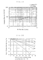
- FIG. 18 is a graph indicating the results obtained for
the relationship between the flow rate of air and the filtration
flow rate for the aforementioned filtration membrane module in
a verification test.
- FIG. 19 is a graph indicating the results obtained for
the relationship between the flow rate of air and the filtration
flow rate for a flat sheet module as a comparison example in
a verification test.
- FIG. 20 is a graph indicating the relationship between
the proportion of tubular membranes having a small flow rate
of air and the filtration flow rate in the aforementioned
filtration membrane module.
- FIG. 21 is a graph indicating the relationship between
the number of air bubbles spouting pores placed in an air bubbles
supply device adopted for the aforementioned immersion type
membrane filter apparatus, the diameter of the area occupied
by tubular membranes, and the diameter of air bubbles, in the
aforementioned filtration membrane module.
- FIG. 22 is a graph indicating the results of
constant-pressure filtration testing conducted for verifying
the backwash conditions by means of the aforementioned back
washing device.
- FIG. 23 is a graph indicating the results of quantitative
filtration testing conducted for verifying the backwash
conditions by means of the aforementioned back washing device.
- FIG. 24 is a diagram corresponding to FIG. 11 of a
variation example of the aforementioned immersion type membrane
filter apparatus.
- FIG. 25 is a plane view of a plain body for use in an air
bubbles supply device adopted for an immersion type membrane
filter apparatus concerning the aforementioned variation
example.
- FIG. 26 is a diagram corresponding to FIG. 11 of another
variation example of the aforementioned immersion type membrane
filter apparatus.
- FIG. 27 is a longitudinal section of a filtration membrane
module of another embodiment capable of being utilized in the
aforementioned immersion type membrane filter apparatus.
- FIG. 28 is a diagram corresponding to the XXVIII-XXVIII
section of FIG. 27 of another embodiment of the aforementioned
filtration membrane module.
- FIG. 29 is a diagram indicating a step of manufacturing
the other embodiment of the aforementioned filtration membrane
module.
- FIG. 30 is a diagram indicating another step of
manufacturing the other embodiment of the aforementioned
filtration membrane module.
- FIG. 31 is a diagram corresponding to FIG. 27 of a
variation example of the other embodiment of the aforementioned
filtration membrane module.
- FIG. 32 is a longitudinal section of a filtration membrane
module of a further embodiment capable of being utilized in the
aforementioned immersion type membrane filter apparatus.
- FIG. 33 is a diagram corresponding to the XXXIII-XXXIII
section of FIG. 32 of the further embodiment of the
aforementioned filtration membrane module.
- FIG. 34 is a diagram corresponding to FIG. 11 of a guide
column concerning a variation example used when adopting the
further embodiment of the aforementioned filtration membrane
module.
- FIG. 35 is a diagram corresponding to the XXXV-XXXV
section of FIG. 34 of the aforementioned guide column regarding
a variation example.
- FIG. 36 is a diagram corresponding to FIG. 7 of a variation
example of a tubular membrane for use in the aforementioned
filtration membrane module.
- FIG. 37 is a development of an example of a group of tubular
membranes capable of being utilized in the aforementioned
filtration membrane module.
- FIG. 38 is the XXXVIII-XXXVIII sectional view of FIG. 37.
- FIG. 39 is a longitudinal section of a variation example
of the filtration membrane module shown in FIG. 2.
- FIG. 40 is a longitudinal section of a variation example
of the filtration membrane module shown in FIG. 27.
- FIG. 41 is a schematic diagram of the filtration flow rate
measuring device used in Experimental Example 5.
- FIG. 42 is a schematic diagram of the filtration flow rate
measuring device used in Experimental Example 8.
- FIG. 43 is a schematic diagram of the filtration flow rate
measuring device used in Experimental Example 9.
- FIG. 44 is a diagram indicating the positions of the air
bubbles spouting pores placed in the air bubbles supply device
used in Comparative Experimental Example 1 in contrast to the
positions of the air bubbles spouting pores placed in the air
bubbles supply device used in Experimental Example 9.
- FIG. 45 is a schematic diagram of the filtration flow rate
measuring device used in Experimental Example 10.
- FIG. 46 is a partly omitted bottom view of the air bubbles
supply device used in Comparative Experimental Example 2.
- FIG. 47 is a schematic diagram of the filtration flow rate
measuring device used in Experimental Example 11.
-
Best Mode for Carrying Out the Invention
-
Referring to FIG. 1, there will be described an immersion
type membrane filtration system having adopted therein an
immersion type membrane filter apparatus regarding an .
embodiment of the present invention. In the figure, an
immersion type membrane filtration system 100 is primarily
provided with a storage bath 150 and an immersion type membrane
filter apparatus 200.
-
The storage bath 150 is formed in a vessel form having
an opening at the top thereof and stores therein a fluid to be
processed. In addition, the storage bath 150 is provided with
a supply passage (not shown) of a fluid to be processed.
-
The immersion type membrane filter apparatus 200 is
primarily provided with a filtration membrane module 300
disposed within the storage bath 150, a guide column 400
supporting the filtration membrane module 300 within the
storage bath 150, an air bubbles supply device 500, a filtrate
discharge pathway 600, and a backwashing device 700.
-
The filtration membrane module 300, as shown in FIG. 2,
is mainly equipped with a cylindrical housing vessel 301 and
a group of tubular membranes 302 packed in this housing vessel
301. The housing vessel 301 is, for example, a resin member
and has on the side thereof a discharge port 303 for discharging
a processed fluid (filtrate) subsequent to filtration
processing. In addition, the inner periphery of the housing
vessel 301 has at the upper and lower portions thereof spacers
304 for creating clearances between the group of tubular
membranes 302 and the inner periphery of the housing vessel 301,
the spacer 304 protruding toward the center.
-
The spacer 304 is formed into roughly a wedge shape in
section shape that enlarges toward the center side of the
housing vessel 301. Also, as illustrated in FIGS. 3, 4 and 5,
it possesses a plurality of slits 305 formed at roughly regular
intervals in the circumferential direction of the housing
vessel 301. Additionally, the spacers 304, 304 placed at the
upper and lower portions of the housing vessel are respectively
set such that the protrusion distances from the inner periphery
of the housing vessel 301 are the same.
-
In addition, it is preferable that the cross-sectional
area of each spacer 304 is set to the ratio of 3 to 10% with
respect to the cross-sectional area inside the housing vessel
301 (corresponding to a shaded portion in FIG. 3) in a
cross-section perpendicular to the housing vessel 301 in the
axial direction in the portion having the spacer 304
(cross-section at the central portion of the spacer 304 in the
vertical direction, i.e., the cross-section taken along the
ii-ii portion of FIG. 2). At the ratio less than 3%, clearances
are hard to form in the inner periphery of the housing vessel
301, in particular between the discharge port 303 and the group
of tubular membranes 302. As a result, within the housing
vessel 301, a processed fluid (filtrate) having passed through
a tubular membrane 310 described below declines in flowability
leading to the possibility of decrease in the filtration flow
rate. In contrast, at the rate exceeding 10%, the ratio of
occupation of the group of tubular membranes 302 within the
housing vessel 301 decreases, thus resulting in the possibility
of decline in filtration efficiency of a fluid to be processed.
-
The group of tubular membranes 302 is a group containing
a large number of slenderly, cylindrically formed tubular
membranes 310. Each of the tubular membranes 310 is compactly
collected along the opening direction of the housing vessel 301
in parallel to each other while being prevented from contacting
with each other (i.e. making intervals to each other) by a
protrusion 320 mentioned below. The upper and the lower ends
of this group of tubular membranes 302 are maintained and fixed
integrally to both ends of the housing vessel 301 by means of
support portions 306 fabricated using a resin material such as
an urethane resin while keeping an open state of both ends of
each of the tubular membranes 310. In addition, both ends of
the housing vessel 301 are liquid-tightly sealed by the support
portions 306.
-
The tubular membranes 310 constituting the above-mentioned
group of tubular membranes 302 is cylindrically
formed as illustrated in FIG. 6 and, as shown in FIG. 7, possesses
a two-layer structure comprising a filtration membrane layer
311 and a support membrane layer 312 in the order from the inner
periphery side toward the outer periphery side.
-
The kind of filtration membrane layer 311 can be selected
as appropriate according to the type of components to be
filtrated to be removed from the fluid to be processed and is
not particularly limited. For example, when particulates such
as microorganisms need to be removed, a microfiltration
membrane is employed. A microfiltration membrane is defined
as, for example in JIS K 3802 "a membrane used for separating
by filtration particulates and microorganisms of about 0.01 to
several micrometers." In this case, it is preferable that a
porous membrane having numerous pores with a pore size exceeding
0.04 µm and being capable of practical filtration at a pressure
of 20 kPa or less is utilized. In this connection, such a
microfiltration membrane is not particularly limited in kind,
but known various types, for example, organic polymer membranes
such as a cellulose membrane and polyolefin base resin membrane
can be employed.
-
A support membrane layer 312 imparts shape keeping
property to the above-mentioned filtration membrane layer 311
and sets the filtration membrane layer 311 in a cylindrical
shape. This support membrane layer 312 can use a variety of
types if they are porous materials having liquid permeability.
Normally, it preferably uses an unwoven cloth of polypropylene
resin or polyester resin possessing firm preservation
properties, excellent strength, excellent chemical resistance,
high thermal resistance and cost efficiency, and particularly
preferably uses an unwoven cloth of polyester resin.
-
In addition, the tubular membrane 310, as illustrated in
FIG. 6, has the protrusion 320 continuously formed in a helical
fashion, with the axis of the filtration membrane layer 311
being the center thereof, on the outer periphery and thus on
the outer periphery of the support membrane layer 312. This
protrusion 320 prevents the tubular membranes 310 from coming
in contact with each other in the group of tubular membranes
302 and enhances the flowability of a processed fluid (filtrate)
having passed through each of the tubular membranes 310 within
the housing vessel 301.
-
For example, when the height of the protrusion 320 is set
at 0.05 mm and if the effective length of the tubular membrane
310 is for example 70 cm, an area of at least 0.005 x 70 = 0.35
cm2 is secured between two neighboring tubular membranes 310.
Accordingly, the presence of a large number of such clearances
in the group of tubular membranes 302 remarkably reduces the
resistance to the flow of filtrate within the housing vessel
301, thereby significantly increasing the flowability of the
filtrate.
-
The inside diameter (X in FIG. 7) of the tubular membrane
310 as mentioned above is normally preferably set at from 3 to
15 mm, more preferably at from 5 to 10 mm. At the inside diameter
less than 3 mm, the filtration of a fluid to be processed,
particularly a highly contaminated fluid to be processed,
readily suffers clogging of the tubular membrane 310 due to a
variety of components to be filtrated or contaminants contained
in the fluid to be processed, thus leading to the possibility
of difficulty in keeping stable, continuous filtration
processing for extended periods of time. In contrast, at the
inside diameter above 15 mm, the number of the tubular membranes
310 to be contained in the group of tubular membranes 302
packable in the housing vessel 301 having a limited volume is
decreased, and therefore the filtration area (effective
membrane area) per volume of filtration membrane module 300
becomes small. As a result, a resulting decrease in filtration
flow rate may create difficulty in conducting an efficient
filtration processing of a fluid to be processed, with
miniaturization of the filtration membrane module 300.
-
In addition, in the tubular membrane 310, the ratio (A/B)
of the wall thickness A to the outside diameter B is preferably
set at from 0.025 to 0.1, more preferably set at from 0.03 to
0.1. Incidentally, the wall thickness and outside diameter of
the tubular membrane 310 in this case includes the thickness
(height) of the aforementioned protrusion 320. At this ratio
below 0.025, application of pressure to the tubular membrane
310 from the outside leads to easy collapse of the tubular
membrane 310. This dislodges a cake layer including components
to be filtrated accumulated on the inner periphery of the
tubular membrane 310 in the step of filtrating the fluid to be
processed. Therefore, when a backwashing operation is
conducted by applying a pressure to the tubular membrane 310
from the outside, the tubular membrane 310 collapses, thus
creating a substantial difficulty in backwashing the tubular
membrane 310. In addition, for attaining a pressure resistance
of 20 kPa or more, the ratio is preferably set at 0.03 or more.
On the other hand, at this ratio above 0.1, the filtration area
(effective membrane area) per volume of filtration membrane
module 300 becomes small. This drops the filtration flow rate,
which may create difficulty in conducting an efficient
filtration processing of a fluid to be processed, with
miniaturization of the filtration membrane module 300.
-
In the above-mentioned tubular membrane 310, the ratio
of the wall thickness to the outside diameter is specified as
stated above, and so the crushing pressure is large. In
particular, when this ratio is 0.03 or more, the crushing
pressure of the tubular membrane 310 can be set at an upper limit
of 20 kPa or more of the filtration pressure normally set in
the immersion type filtration process, and thus can be set at
least at 20 kPa. Incidentally, the term "crushing pressure"
refers to a pressure when the tubular membrane 310 starts to
collapse in the case where a pressure is applied from the outside
of the tubular membrane 310 (i.e. the support membrane layer
312 side) to the inside thereof.
-
In this connection, the crushing pressure of the tubular
membrane 310 is proportional to the third power of the ratio
of the wall thickness to the outside diameter (See, for example,
"Handbook for Charts of Machinery Design," written by Fujio
Oguri, 9-2, Kyoritsu Shuppan Co., Ltd.), which means that the
crushing pressure is increased as the ratio is increased.
-
Furthermore, the height of the protrusion 320 is normally
preferably set at from 0.02 to 0.2 mm. At the height of the
protrusion 320 below 0.02 mm, the tubular membranes 310 readily
come into contact with each other in the group of tubular
membranes 302, thus probably making it difficult to increase
the flowability of filtrate. In contrast, at the ratio above
0.2 mm, the number of the tubular membranes 310 contained in
the group of tubular membranes 302 and thus the number of tubular
membranes 310 packable in the housing vessel 301 of the
filtration membrane module 300 is decreased, and thereby the
filtration area per volume of filtration membrane module 300
becomes small. This drops the filtration flow rate, which may
create difficulty in conducting an efficient filtration
processing of a fluid to be processed, with miniaturization of
the filtration membrane module 300. Incidentally, the height
of the protrusion 320 in this case refers to the extent of
protrusion from the surface of the support membrane layer 312.
-
The height of the protrusion 320 can be selected as
appropriate according to the kind of fluids to be processed as
well. For example, when the filtration flow rate of a fluid
to be processed is comparatively small like that of an activated
sludge fluid, the height of the protrusion 320 is preferably
set to be smaller from the viewpoint of securing the filtration
area. On the other hand, where the filtration flow rate of a
fluid to be processed is relatively large as in water of rivers,
the height of the protrusion 320 is preferably set to be higher
from the viewpoint of increasing the flowability of the filtrate.
In this connection, if the height of the protrusion 320 is within
the above-mentioned range, even for a large-scale case where
the filtration membrane module 300 has a membrane area of about
100 m2, the clearances, formed by the protrusion 320, between
the tubular membranes 310 rarely have a large resistance to the
flow of filtrate for most fluids to be processed.
-
Next, referring to FIG. 8 there will be described an
example of a method for producing the above-mentioned tubular
membranes 310.
-
First, a large-length and small-width (tape-like)
composite membrane 313 fabricated by integrally laminating
the filtration membrane layer 311 on the support membrane layer
312 is prepared. Then, this composite membrane 313, as
illustrated in FIG. 8, is wound spirally around a separately
prepared columnar rod 315 in such a way that the support membrane
layer 312 side becomes the surface side while overlapping both
ends 314 in the widthwise direction. Both the ends 314
overlapped in this manner are bonded with each other using an
adhesive or the ultrasonic adhesion method to be able to a target
tubular membrane 310. Incidentally, a method of producing such
a tubular membrane 310 is already well-known, for example, in
Japanese Patent Laid-Open No. 56-35483.
-
In a manufacturing step of such a tubular membrane 310,
both the ends 314 made by overlapping the composite membrane
313 come to form the aforementioned helical protrusion 320.
During this time, adjusting as appropriate the extent of overlap
of the composite membrane 313 or the adhesion method enables
setting of the height of the protrusion 320 within the
above-mentioned range.
-
Now, with reference to FIGS. 9 and 10, there will be
described a method of producing the above-mentioned filtration
membrane module 300. This filtration membrane module 300 can
be readily manufactured by a simple step as compared with a flat
sheet module or a hollow fiber module in which the handling of
the flat sheet membrane or the hollow fiber membrane requires
close attention as well as the production requiring numerous
manufacturing steps.
-
First, a large number of the tubular membranes 310 are
bundled up to form the group of tubular membranes 302.
Separately, the housing vessel 301 is prepared and, as shown
in FIG. 9, the group of tubular membranes 302 is inserted into
this housing vessel 301 to form a combination 330 of the housing
vessel 301 and the group of tubular membranes 302. In this
combination 330, the group of tubular membranes 302 is set in
such a way that both ends of the group of tubular membranes 302
are projected from both ends of the housing vessel 301.
Additionally, both ends of the tubular membranes 310
constituting the group of tubular membranes 302 are rendered
to be closed by, for example, heat sealing.
-
Thereafter, as shown in FIG. 10, one end of the
aforementioned combination 330 is soaked in a mold 332
containing an uncured resin 331 such as an uncured urethane
resin. Here, the uncured resin 331 is loaded in between the
tubular membranes 310 constituting the group of tubular
membranes 302 as well as uniformly reaching the inner periphery
of the housing vessel 301 past the slits 305 placed in the spacers
304, thus completely closing the opening portion of the housing
vessel 301. In this state, the resin 331 is cured completely
and then the mold 332 is removed. A similar operation is
performed on the other end of the combination 330 as well. In
this way, the group of tubular membranes 302 comes to be
maintained and fixed to the housing vessel 301.
-
Then, cured resin portions protruded from both the ends
of the housing vessel 301 are cut off along with both the ends
of the tubular membranes 310, so that the remaining resin
portions form the support portions 306. Also, both ends of each
of the tubular membranes 310 are opened to obtain the target
filtration membrane module 300. In this filtration membrane
module 300, both ends of the housing vessel 301 without both
ends of each of the tubular membranes 310, as stated earlier,
are liquid-tightly closed by means of the cured resin and thus
the support portions 306. These support portions 306 are likely
to be strongly fixed to the inner periphery of the housing vessel
and come to cause the group of tubular membranes 302 to stably
be maintained and fixed to the housing vessel 301 because the
spacer 304 of the housing vessel 301 is formed convexly in the
form of a wedge as described above. In other words, the spacers
304 not only simply create clearances between the group of
tubular membranes 302 and the inner periphery of the housing
vessel 301, but also are capable of functioning as the convex
portion for stably fixing the support portions 306 and the
housing vessel 301.
-
Furthermore, in both ends of the housing vessel 301, the
inner periphery thereof may have, for example, a groove-like
concave portion in ring form. In this case, the resin 331 flows
into the concave portion to more strongly fix the support
portions 306 and the housing vessel 301.
-
Usable materials for fabricating the support portion 306
include, in addition to urethane resins as stated above, other
thermosetting resins such as epoxy resins and hot melt adhesives .
However, when a large-scale filtration membrane module 300 is
manufactured, the amount of resin material to be used needs to
be set in quantity. In this case, a material having a relatively
slow reaction rate and having a relatively small elasticity is
preferably used in order to suppress excessive heat liberation
and to suppress contraction by curing. In addition, a hot melt
adhesive that is cut off in the above-mentioned manufacturing
step can be recovered for reuse. In this respect as well, the
filtration membrane module 300 is advantageous as compared with
a hollow fiber module in which a hot melt adhesive is difficult
to utilize due to a relatively high viscosity thereof.
-
Further, in FIG. 2 and so forth concerning the filtration
membrane module 300, for convenience in understanding, there
are stressed the thickness of the tubular membrane 310,
clearances between the tubular membranes 310, clearances
between the tubular membranes 310 and the inner periphery of
the housing vessel 301, etc. In addition, for readily
understanding diagrams, in FIG. 2, the tubular membranes 310
are expressed in a smaller number than in an actual number and
only part of the tubular membranes 310 is presented in FIG. 3.
-
The guide column 400, as shown in FIG. 1, supports the
filtration membrane module 300 within the storage bath 150 in
a stand-up state such that the tubular membranes 310 open in
the vertical direction. The guide column 400 is a cylindrical
resin member and the inner circumferential line in the cross
section vertical to the axial direction thereof is set to be
substantially the same size and shape as the inner
circumferential line of the outer circumferential portion in
the cross section vertical to the axial direction of the housing
vessel 301. In other words, the guide column 400 has the same
inside diameter and outside diameter as those of the housing
vessel 301.
-
In the lower edge of the guide column 400, as illustrated
in FIG. 11, a flange 401 equipped with a leg 402 is placed. The
guide column 400 is disposed in the bottom of the storage bath
150 by means of the legs 402 and on the upper portion thereof
is placed the filtration membrane module 300. Here, the guide
column 400 and the filtration membrane module 300 are connected
to each other by means of a cylindrical socket 403 (FIG. 1).
The filtration membrane module 300 is supported using this guide
column 400, and thus is positioned separately from the bottom
of the storage bath 150.
-
The air bubbles supply device 500 is intended for
supplying air bubbles to the filtration membrane module 300.
As illustrated in FIG. 1, it is disposed within the guide column
400 beneath the filtration membrane module 300 in the storage
bath 150.
-
Referring to FIGS. 11 and 12, the air bubbles supply
device 500 will be described in detail. The air bubbles supply
device 500 primarily possesses a first pipe 501, a second pipe
502, and four branch pipes 503, 504, 505 and 506. The first
pipe 501 is placed horizontally such that it penetrates through
the guide column 400 and passes through the center thereof
within the guide column 400. One end of it is hermetically
closed with a cap 507 in the outside of the guide column 400.
Also, the second pipe 502 horizontally combines and intersects
with the first pipe 501 at right angles, with both the ends of
the second pipe 502 each penetrating the wall of the guide column
400 and being hermetically closed with the caps 507. In
addition, the intersection of the first pipe 501 and the second
pipe 502 coincides with the center of the guide column 400.
Furthermore, the four branch pipes 503, 504, 505 and 506 combine
with the second pipe 502 parallel and horizontally, with two
pipes each being distributed to both sides of the first pipe
501. The branch pipes 504, 503 are placed at regular intervals
from the first pipe 501. The branch pipes 505, 506 are also
placed in the same fashion. Accordingly, the first pipe 501
and the four branch pipes 503, 504, 505 and 506 are disposed
at regular intervals . Additionally, both the ends of the branch
pipes 503, 504, 505 and 506 each extend toward near the inner
periphery of the guide column 400 and hermetically closed with
caps (not shown).
-
The first pipe 501 and the second pipe 502 combined with
each other as mentioned above are communicated at the
intersection. Also, the four branch pipes 503, 504, 505 and
506 are communicated with the second pipe 502 at the
intersections with the second pipe 502. As a result, the first
pipe 501, the second pipe 502 and the four branch pipes 503,
504, 505 and 506 form a series of air flowing pathways.
-
In addition, the first pipe 501, the second pipe 502 and
the four branch pipes 503, 504, 505 and 506 possess a plurality
of air bubbles spouting pores 510 for spouting air in the form
of bubbles (with FIG. 12 showing, for example, 19 air bubbles
spouting pores 510). These air bubbles spouting pores 510 each
are opened toward the bottom face of the storage bath 150. Also,
as illustrated in FIG. 12, they are placed in a closest packing
pattern in the inside (horizontal face of the inside of the guide
column 400) of the section vertical to the axial direction of
the guide column 400. In other words, each air bubbles spouting
pore 510 is dispersedly disposed at regular intervals in the
horizontal face of the inside of the guide column 400 in such
a way that the air bubbles spouting pore 510 is positioned at
each vertex of numerous equilateral triangles as indicated by
an alternate long and short dash line in FIG. 12.
-
In addition, the material of the pipes 501 to 506
constituting the aforementioned air bubbles supply device 500
is not particularly restricted if it does not prevent the
circulating flow of a fluid to be processed caused by an
ascending flow of air bubbles being emitted from the air bubbles
spouting pores 510. However, the pipe is normally preferably
a cylindrical plastic pipe in terms of cost efficiency,
processability, and easiness of installation to the guide
column 400.
-
To the first pipe 501 of the aforementioned air bubbles
supply device 500, as illustrated in FIG. 1, is connected an
air supply device 525 such as an air compressor by way of an
air supply pathway 521 equipped with a secondary pressure/flow
rate adjusting valve 520. This renders air from the air supply
device 525 to be supplied to the first pipe 501 as well as the
second pipe 502 and the four branch pipes 503, 504, 505 and 506,
communicated therewith.
-
The filtrate discharge pathway 600 is intended for
discharging filtrated fluid, i.e. filtrate, processed in the
filtration membrane module 300 into the outside. It is provided
with a first discharge pathway 601 coming from the discharge
port 303 of the filtration membrane module 300 and a second
discharge pathway 602 for discharging the filtrate through a
backwashing device 700. The second discharge pathway 602
possesses a first electromagnetic valve 603, with the tip
portion 604 thereof being located below the surface L of a liquid
to be processed stored in the storage bath 150. This generates
a water head pressure P between the tip portion 604 and the
surface L of the fluid to be processed.
-
The backwashing device 700 is provided with a
quantitative float valve 710 (an example of back-flow rate
setting devices) and is placed in the filtrate discharge pathway
600 and thus between the first discharge pathway 601 and the
second discharge pathway 602. The quantitative float valve 710,
as illustrated in FIG. 13, is primarily equipped with a float
valve portion 711, a fluid amount setting pipe 712 and a
three-way pipe 713. The float valve portion 711, as shown in
FIG. 14, is equipped with a float receiver 714 and a float 715.
The float receiver 714 is a columnar member with a pathway 716
of filtrate being formed in the axial direction thereof. It
possesses a taper portion 717 expanding toward the outside
direction at the upper end of the pathway 716. Also, the lower
end of the pathway 716 has an opening 718 in the center and is
fabricated in net form. On the other hand, the float 715 is
floatable in filtrate and is spherically formed so as to be
capable of closing the pathway 716 when it makes contact with
the aforementioned taper portion 717. The float 715 is equipped
with a polyester resin filament 730 that extends downward. The
filament 730 extends downward through the opening 718 beneath
the float receiver 714 and has a float stopper 719 at the lower
end.
-
The above-mentioned float valve portion 711, as
illustrated in FIG. 13, renders the lower end of the float
receiver 714 to be connected to the tip of the first discharge
pathway 601 of the filtrate discharge pathway 600 by means of
a socket 720.
-
The fluid amount setting pipe 712 is intended for
controlling the volume of filtrate residing within the
quantitative float valve 710 and is communicated with the upper
end of the float receiver 714 using a socket 721.
-
The three-way pipe 713 possesses a first connection
portion 722 having a slightly larger aperture and two slightly
smaller connection portions compared with the first connection
portion 722, i.e. a second connection portion 723 and a third
connection portion 724. The first connection portion 722 is
connected to the upper end side of the fluid amount setting pipe
712 by means of a socket 725. In addition, the second connection
portion 723 is connected to the second discharge pathway 602
of the filtrate discharge pathway 600. Furthermore, the third
connection portion 724 is communicated with a backwashing air
supply pathway 530 (an example of pressurizing means), which
branches from the above-mentioned air supply pathway 521 and
extends. Additionally, the backwashing air supply pathway 530
has a secondary pressure/flow rate adjusting valve 531 and a
second electromagnetic valve 532 in the order from the air
supply pathway 521 side (FIG. 1).
-
Now, with reference to FIG. 1, there will be described
a method for filtrating a fluid to be processed using the
aforementioned immersion type membrane filter apparatus 200
(immersion type membrane filtration method).
-
First, into the storage bath 150 is supplied and stored
a fluid to be processed containing components to be filtrated
including micro-gel, colloid components and microorganisms,
for example, an activated sludge fluid to be processed of
domestic wastewater. This event makes the filtration membrane
module 300 disposed within the storage bath 150 to be immersed
in the fluid to be processed.
-
Then, the second electromagnetic valve 532 of the
backwashing air supply pathway 530 is set closed and the first
electromagnetic valve 603 of the second discharge pathway 602
is set open. In this state, when air is supplied to the air
bubbles supply device 500 from the air supply device 525 via
the air supply pathway 521, this air spouts from the air bubbles
spouting pores 510 in the form of bubbles. These air bubbles
rise in the fluid to be processed while receiving a guide by
the guide column 400 and are almost uniformly supplied to each
of the tubular membranes 310 contained in the filtration
membrane module 300.
-
The buoyancy of air bubbles supplied to the filtration
membrane module 300 renders the fluid to be processed stored
in the storage bath 150 to pass through each of the tubular
membranes 310 from the lower side upwards as indicated by arrows
in FIG. 2. During this time, part of the fluid to be processed
is made to filtrate and pass through the tubular membranes 310
from the inside toward the outside by the above-mentioned water
head pressure P. Also, components to be filtrated contained
in the fluid to be processed are captured by the filtration
membrane layers 311 constituting the inner periphery of the
tubular membranes 310 to be dislodged from the fluid to be
processed. The processed fluid from which the components to
be filtrated are dislodged and thus the filtrate passes through
clearances between the tubular membranes 310 within the housing
vessel 301 and then is discharged from the discharge port 303
into the first discharge pathway 601. The filtrate discharged
into the first discharge pathway 601 passes through the
quantitative float valve 710 and then is continuously
discharged into the outside from the tip portion 604 of the
second discharge pathway 602.
-
At this time, although the float 715 along with the float
stopper 719 is made floated by the filtrate that is passing to
set the pathway 716 in a open state, the float stopper 719 makes
contact with the opening 718 to prevent the float 715 from
separating from the float receiver 714 at a specified distance
or more. Such a series of filtration conducts causes the fluid
to be processed within the storage bath 150 to naturally
circulate through the filtration membrane module 300 from the
lower side upwards, as indicated by the arrows in FIG.1.
-
In the filtrating step as mentioned above, each of the
tubular membranes 310 has the protrusion 320 on the outer
periphery as stated earlier, and so it hardly makes contact with
the neighboring tubular membranes 310 within the filtration
membrane module 300 to form effective clearances for passing
the filtrate between the tubular membranes 310. Therefore, the
filtration membrane module 300 equipped with these tubular
membranes 310 can enhance the flowability of the filtrate within
the housing vessel 301, thereby readily discharging the
filtrate at the discharge port 303 without a hitch.
-
In addition, in the filtrating step as mentioned above,
components to be filtrated contained in a fluid to be processed
gradually deposit on the inner periphery of the tubular
membranes 310 and thus the surface of the filtration membrane
layers 311 to form cake layer, thereby lowering the filtration
performance of the tubular membranes 310. In this case,
backwashing operation by means of the backwashing device 700
dislodges the cake layers of the tubular membranes 310 to be
capable of recovering the filtration performance. For the
conduct of backwashing operation, first, the second
electromagnetic valve 532 of the backwashing air supply pathway
530 is set open and the first electromagnetic valve 603 of the
second discharge pathway 602 is set closed. This operation
adjusts the flow rate of air from the air generating device 530
at the secondary pressure/flow rate adjusting valve 531 and
flows the air within the backwashing air supply pathway 530 to
render it to reach the quantitative float valve 710. The air
having reached the quantitative float valve 710 pushes out the
filtrate within the quantitative float valve 710 by means of
a pressure (air pressure) corresponding to a flow rate adjusted
at the secondary pressure/flow rate adjusting valve 531 toward
the first discharge pathway 601. This causes the filtrate
within the quantitative float valve 710 and the first discharge
pathway 601 to backflow from the discharge port 303 into the
filtration membrane module 300 and to pass with the pressure
corresponding to the above-mentioned air pressure through each
of the tubular membranes 310 from the outside toward the inside.
As a result, in each of the tubular membranes 310, the deposit
layers (cake layers) accumulated on the inner periphery due to
components to be filtrated are dislodged and thus cleaned.
-
In the backwashing step as mentioned above, in the
quantitative float valve 710, when filtrate within the fluid
amount setting pipe 712 and the three-way pipe 713 is pushed
out, the float 715 makes contact with the taper portion 717 of
the float receiver 714 due to its own weight to close the pathway
716. Because of this, the amount of filtrate flowing back into
the filtration membrane module 300 from the discharge port 303
comes to be limited to the amount specified by the volume of
the quantitative float valve 710 and the first discharge pathway
601. Accordingly, the amount of filtrate used for backwashing
can be set arbitrarily by adjusting the volume of the
quantitative float valve 710, particularly the volume of the
fluid amount setting pipe 712.
-
In addition, in the aforementioned backwashing step, the
flow rate of air to be set by the secondary pressure/flow rate
adjusting valve 531 is preferably set in such a way that the
air pressure corresponding to the flow rate becomes at least
the above-mentioned filtration pressure based on the water head
pressure P, or the above-mentioned filtration pressure or
higher based on the water head pressure P. At this flow rate
of air (i.e. the aforementioned air pressure) less than the
filtration pressure, cleaning of the tubular membranes 310
become insufficient, and thereby the filtration performance of
the tubular membranes 310 is sometimes difficult to recover.
-
In this regard, inasmuch as the tubular membranes 310 has
a large crushing pressure as stated earlier (for example, with
the crushing pressure being set at least at 20 kPa), they are
not crushed by the application of pressure during the
backwashing operation as described above. The membranes 310
maintain the shapes thereof subsequent to backwashing
processing and therefore are continually applicable to the
filtration step as mentioned above. In other words, this
immersion type membrane filter apparatus 200, after the
backwashing operation as described above, can continually
conduct filtration processing when the second electromagnetic
valve 532 of the backwashing air supply pathway 530 is set closed
and the first electromagnetic valve 603 of the second discharge
pathway 602 is set open.
-
Therefore, in the aforementioned immersion type membrane
filtration system 100, periodical repetitions of the above-mentioned
filtration step and the backwashing step with the
operations of the first electromagnetic valve 603 and the second
electromagnetic valve 532 enables the recovery of filtration
performance of the tubular membranes 310 without replacing the
filtration membrane module 300, thereby permitting an efficient
continuation of filtration processing of a fluid to be processed
over extended periods of time.
-
In addition, in the immersion type membrane filter
apparatus 200, the filtration membrane module 300 can be
miniaturized as described in detail below and also the air
supply device 525 is used for both the air supply source for
the air bubbles supply device 500 and the air supply source for
the backwashing device 700. Hence, the whole structure of the
apparatus 200 can be miniaturized and also the apparatus 200
can carry out cost efficient filtration step and backwashing
step.
-
Incidentally, in the aforementioned immersion type
membrane filtration method, the first electromagnetic valve 603
and the second electromagnetic valve 532 may be manually run
or may be automatically run using a timer.
-
Additionally, the above-mentioned immersion type
membrane filter apparatus 200 is particularly effective in
filtrating highly contaminated fluids such as an activated
sludge fluid. It is also effectively utilizable for filtrating
low contaminated fluids such as river water in addition to such
a highly contaminated fluid. In other words, the immersion type
membrane filter apparatus 200 does not depend on the kind of
fluids to be processed, and is widely usable for filtrating a
variety of fluids to be processed.
-
Next, comparing to the conventional filtration membrane
module, the possibility of compaction and the cost efficiency
of the filtration membrane module 300 using the tubular
membranes 310 will be discussed. In addition, in this
connection, the relationship between distribution states of air
bubbles supplied to the filtration membrane module 300 from the
air bubbles supply device 500 and filtration properties is also
discussed for depicting in more detail an optimal configuration
pattern of the air bubbles spouting pores 510 in the air bubbles
supply device 500. Moreover, effective backwash conditions of
the filtration membrane module 300 by means of the backwashing
device 700 will be discussed.
-
Incidentally, by estimating scientifically the
characteristics of the filtration membrane module 300 using the
tubular membranes 310, many advantages over those of a hollow
fiber module or a flat sheet module are found out. For example,
they include:
- 1. the flow of all the air bubbles from the air bubbles
supply device 500 can be utilizable due to enlarging parallel
flows of cross-flows,
- 2. the material shift factor is large as compared with
that of the conventional module mode and thus the flux
(filtration flow rate per unit membrane area) is in principle
large because of the pathways of air bubbles and a fluid to be
processed being cylindrical,
- 3. the structure of the filtration membrane module 300
becomes compact because the tubular membranes 310 themselves
constitute the pathways of air bubbles and a fluid to be
processed, and
- 4. the pressure loss being small and the backwashing
efficacy being large due to the inside diameter of the tubular
membranes 310 being by far larger than that of hollow fiber
membranes.
Recently, technologies for effectively removing contaminants
contained in fluids to be processed have been greatly advanced,
and so possibilities of realizing these advantages are being
increased. -
-
However, in order to show that the above-mentioned
advantages are not limited to specific actual fluids, but are
general and basical, first, it is necessary to analyze
hydrodynamically the filtration properties of the filtration
membrane module 300 using the tubular membranes 310 comparing
with the conventional filtration membrane module and then to
inspect the results by means of an appropriate model fluid.
Doing so is thought to lead to the possibility of utilizing the
same advantages in many actual fluids also. However, such an
evaluation method is unknown, and therefore the properties of
the filtration membrane module 300 are unknown in principle and
scientifically as well. Further, even though such an
evaluation method is established and thereby the advantages of
the filtration membrane module 300 are proved generally and in
principle, a designing method of realizing more effectively the
advantages on the filtration membrane module 300 needs to be
made concrete.
Analytical Estimation of the Properties of Filtration Membrane
Modules
-
As seen in the "Report on Commercialization of Small-Size
Domestic Wastewater Processing Apparatus that Introduces
a Membrane Processing Method, 1992 to 1995 Edition," published
by Japan Education Center of Environmental Sanitation referred
in the description of "Background Art," fluxes are larger in
the flat sheet module than in the hollow fiber module. For this
reason, a flat sheet module has been selected as the
conventional module for a comparison target.
-
For reference, referring to FIG. 15, there will be briefly
described a flat sheet module as a comparison target. In the
figure, a flat sheet module 800 is primarily provided with a
housing vessel 801 and a number of membrane plates 802 disposed
within this housing vessel 801. The housing vessel 801 is, for
example, a squared column-like member having the upper and lower
portions each opened. On the other hand, the membrane plate
802, as illustrated in FIG. 16, is primarily provided with a
rectangular frame 803 and a pair of filtration membranes 805,
805 opposed to each other in a clearance 804 in the frame 803.
This filtration membrane 805 is for example a microfiltration
membrane. At the upper portion of the frame 803, a discharge
port 806 of filtrate, communicating with the clearance 804, is
fabricated. The discharge port 806 of each of the membrane
plates 802 is normally, as shown in FIG. 15, connected to a
discharge tube 807. Incidentally, this type of flat sheet
module 800 is briefly explained in, for example, the "Water and
Wastewater" Vol. 40, No. 3, 45 (1998), edited by the Research
Association on High-Processing Clarifying Bathes Using
Membrane Separation Technologies at Construction Research
Institute in Japanese Ministry of Construction.
-
Such a flat sheet module 800 is placed in a storage bath
150 like the aforementioned filtration membrane module 300 to
be made available for immersion type membrane filtration of
fluids to be processed. In this case, a fluid to be processed
together with air bubbles, flowing between the membrane plates
802, flows from the outside of the filtration membranes 805 to
the inside thereof to thereby be filtrated. Then, the filtrate
at this time passes through the clearance 804 and is discharged
into a discharge tube 807 by way of the discharge port 806.
-
In Table 1, main properties of a filtration membrane
module 300 as mentioned above (hereinafter, this filtration
membrane module is sometimes expressed as the "tubular module")
and a flat sheet module 800 as described above are summarized.
Here, to avoid unnecessary complication, the lengths L's of the
membranes of both modules have been set to be the same. For
the same reason, with the areas for setting the modules, the
areas occupied by the membrane portions are indicated excluding
the thickness of the housing vessel 301 for the filtration
membrane module 300 and the thickness of the frame 803 for the
flat sheet module 800.
| Module type | Membrane size | Number | Total membrane area | Module setting area | Flow rate of air |
| Tubular module | Tubular membrane size | Number of tubular membranes | MT = πdiLN | ST = πd0 2N/4ε | QT |
| di × d0 × L | N |
| Flat sheet module | Membrane plate size | Number of membrane plates | MP = 2WLn | SP = W(d+t)n | QP |
| W × t × L | n |
| di × d0 : Inside diameter of tubular membrane x outside diameter, |
| ε:Packing rate, |
| W × t:Membrane width of membrane plate × thickness |
| d:Interval between membrane plates |
| Common conditions:n,N>>1 |
-
Incidentally, viscosities of actual fluids (fluids to be
processed) to which immersion type membrane filtration is
applied are a couple of mPa•s and more, and so a flow of a fluid
to be processed within a module can be considered as a laminar
flow for both the flat sheet module 800 and the filtration
membrane module 300.
-
In cross-flow filtration for the parallel flow being a
laminar flow, the filtration flow rate of the filtration
membrane module 300 relative to the flat sheet module 800 is
expressed as Equation (1) below: (For example, refer to the
"Outline on Membrane Processing Technologies" by Nakagaki and
Shimizu, First volume, Chapter 3, Fuji Technosystem Co., Ltd.
(1991))
JT JP =21- a-c MT MP ( d di )1 -c ( diuT duP ) a
wherein J, M and u are, respectively, the filtration flow rate,
the membrane area and the linear velocity of a parallel flow,
and the subscripts T and P indicates the values for the
filtration membrane module 300 and the flat sheet module 800,
respectively. While the parallel flow consists of a mixture
of flows of bubbles and a fluid, the flows are assumed to have
the same moving velocity. d represents an interval between the
membrane plates 802 of the flat sheet module 800 and di
represents an inside diameter of the tubular membrane 310 of
the filtration membrane module 300.
-
Here, the exponents a and c each are 1/3 for the laminar
flow. Therefore, substitution of this value gives Equation (2)
below:
JT JP = 1.26( MT MP )( d di )1/3( uT uP )1/3
-
Wherein assuming that bubbles are uniformly distributed
to all the tubular membranes 310 for the filtration membrane
module 300 and to between all the membrane plates 802 for the
flat sheet module 800, linear velocities for parallel flows for
the modules expressed by Equations (3) and (4) below,
respectively, are derived:
uT = uaT 2 {1+1+2ρ ƒ gd i 2 σTµƒ /(uaT 2 )} [uaT = 4qaT πdi 2 ]
uP = uaP 2 {1+1+2ρ ƒ gd 2 σPµƒ /(uaP 2 )} [uaP = qaP wd ]
-
Wherein qa is the flow rate of air in one flow pathway
equivalent, and the flow rate of air per tubular membrane 310
for the filtration membrane module 300, and the flow rate of
air per interval of membrane plate 802 having a width of w for
the flat sheet module 800. Therefore, ua is the reduced linear
velocity. ρf and µ f are, respectively, the density and the
viscosity of a fluid to be processed. σ is the dimensionless
pressure loss coefficient, and 32 for the filtration membrane
module 300, and 12 for the flat sheet module 800. g is the
gravitational acceleration.
-
As shown in Table 2, the reduced linear velocity can be
converted into the flow rate of air per unit area of membrane,
or the total flow rate per module by means of a numerical value
expressing the shape of each module.
| Type Type | Tubular module Tubular module | Flat sheet module | qM:Flow rate of air per square meter of membrane |
| qM | QT/ (NπdiL) | QP/(2nWL) | ua: Reduced linear velocity of air |
| ua | 4QT/ (Nπdi 2) | QP/ (nWd) | Q: Flow rate of air per module |
| L: Length of membrane |
| Conversion multiplier | 4L/di | 2L/d | N: Number of tubular membranes |
| n: Number of membrane plates |
| (N,n>>1) |
-
From Tables 1 and 2, the linear velocity ratio of the
filtration membrane module 300 to the flat sheet module 800 is
expressed by Equation (5) below:
uT uP =2( QT QP )( MP MT )( d di )1+1+2ρƒgd i 2 32µƒ /(2LQT diMT ) 1+1+ 2ρƒgd 2 12µƒ /( LQP dMP )
-
Use of Equations (2) and (5) can compare the abilities
of the filtration membrane module 300 and the flat sheet module
800 from various standpoints. However, in order to make
simplification without losing actuality, in this case, the
density ρ f of a fluid to be processed is set at 1,000 kg/m3 and
the length L of the membrane at 1 m as common conditions for
both the modules. In addition, the thickness t of the membrane
plate 802 is set at 5 mm for the flat sheet module 800. For
the filtration membrane module 300, the ratio (d0/di) of the
outside diameter d0 to the inside diameter di, of the tubular
membrane 310, is set at 1.2, and the packing rate ε at 0.8 (with
a closest packing state having about 0.9). For the flow rate
of air, a flow rate per unit area of membrane of 15 L/min/m2
normally used in the flat sheet module 800 is selected as the
comparison standard.
-
Table 3 below shows the calculation results for the
viscosity µ
f of a fluid to be processed being set at 10 mPa•s,
the interval
d of the membrane plate 802 being set equal to the
inside diameter
di of the tubular membrane 310, and the total
membrane areas and the total flow rates of air being set equal
for both the modules.
| Comparison conditions | L=1m,QP/MP=15L/min/m2 |
| d=di | Comparison item | d=5mm | d=10mm |
| MP=MT | uT/uP | 1.00 | 0.91 |
| QP=QT | JT/JP | 1.26 | 1.22 |
| | ST/SP | 0.45 | 0.6 |
-
In addition, Table 4 below shows the calculation results
in the same conditions except that the viscosity µ
f of a fluid
to be processed only is changed to 100 mPa•s.
| Comparison conditions | L=1m,QP/MP=15L/min/m2 |
| d=di | Comparison item | d=5mm | d=10mm |
| MP=MT | uT/uP | 1.29 | 1.02 |
| QP=QT | JT/JP | 1.37 | 1.27 |
| | ST/SP | 0.45 | 0.6 |
-
Tables 3 and 4 show that for fluids to be processed having
a wide range of viscosities, the filtration membrane module 300
is larger in filtration flow rate than the flat sheet module
800 although the set area of the former is about 1/2 of that
of the latter.
-
As another example, Table 5 shows the calculation results
for the viscosity µ
f of a fluid to be processed being set at
10 mPa•s, the interval
d of the membrane plate 802 being set
equal to the inside diameter
di of the tubular membrane 310,
and the module set areas and the total flow rates of air being
set equal for both the modules.
| Comparison conditions | L=1m,QP/MP=15L/min/m2 |
| d=di | Comparison item | d=5mm | d=10mm |
| SP=ST | uT/uP | 0.62 | 0.69 |
| QP=QT | JT/JP | 2.39 | 1.86 |
| | MT/MP | 2.22 | 1.67 |
-
Table 5 shows that the filtration membrane module 300 has
a filtration flow rate that is twice or more the filtration flow
rate of the flat sheet module 800 when both the modules have
the same module set area and the same total flow rate of air.
-
Moreover, Tables 3 to 5 indicate that the filtration
membrane module 300 also has a larger flux, the filtration flow
rate divided by the membrane area, than the flat sheet module
800, suggesting that the filtration membrane module 300 is also
excellent in principle as compared with the flat sheet module
800.
-
The analytical examples above show that the filtration
membrane module 300 has an excellent potential in principle as
compared with the flat sheet module 800 and the hollow fiber
module if air bubbles are uniformly distributed to all the
tubular membranes 310. Next, the validity of these analytical
results was inspected by means of model fluids.
Testing Method for Inspecting the Validity of the Analytical
Results
-
In order to study the validation of the analytical results
discussed above, the tests below were investigated. The
details on the testing methods and results will be described
later on. Here, the logical background to the testing methods
for inspecting the validity of the analytical results will be
explained.
-
Use of a specified actual fluid (fluid to be processed)
essentially leads to specific results that reflect its specific
properties, and so the general characteristics of the
filtration membrane module 300 may not be always elucidated.
On the other hand, a basic, scientific evaluation method using
a model fluid having specified properties may generate a concern
about the alienation from an actual fluid. However, unless
dissolved components irreversibly adhere to a membrane and a
cake layer formed by the accumulation of components to be
filtrated on a filtration membrane has a special behavior, and
also if basic, hydrodynamic properties of an actual fluid can
be approximated to a Newtonian fluid as in a model fluid, the
results obtained using the model fluid are thought to hold for
the actual fluid in principle, even though specific ideas need
to be applied to each kind of actual fluids.
-
The present inventors have set the following requirements
for model fluids:
- 1. the characteristics being clear and being simply
capable of being measured,
- 2. the characteristics not being altered within the time
required for testing,
- 3. being readily available and also a third party being
capable of conducting a follow-up study,
- 4. not exhibiting a specific chemical adsorptivity
relative to membranes, and
- 5. having sparing filtration properties.
-
-
Latex and a suspension of clay minerals, which have been
widely utilized as evaluation fluids for microfiltration
membranes, do not meet requirement 5. As a result of
investigating various fluids besides these materials, the
present inventors have found out that aqueous suspension fluids
of carboxymethyl cellulose almost satisfy all requirements 1
to 5 above.
-
Carboxymethyl cellulose is a typical water-soluble
polymer. An aqueous solution thereof is transparent and the
filtration pressure thereof rapidly rises when it is subjected
to constant-speed filtration using a microfiltration membrane.
In addition, inasmuch as the viscosity of a filtrate thereof
is close to that of water, carboxymethyl cellulose seems not
to dissolve in water in the form of molecules, but to suspend
in water as the microgel.
-
It is known that filtration resistance increases when an
activated sludge solution is filtrated by means of the immersion
type membrane filtration method. It is suggested that the cause
is not due to sludge microorganisms, but due to water-soluble
large polymeric materials of secretions thereof (For example,
Shin-ichiro Hamatani et al., the Lecture Collection for the
Presentation on Sewage Water Studies, 37th, 7-90, 2000). In
view of this suggestion, an microgel aqueous suspension of
carboxymethyl cellulose is thought to have a potential as a
suitable filtration model fluid.
-
When the viscosity of a carboxymethyl cellulose aqueous
suspension needs to be greatly changed, relatively large
molecular weight polyethylene oxide is added. Different from
carboxymethyl cellulose, polyethylene oxide almost completely
dissolves in water in a molecular form. The viscosity of the
filtrate obtained by filtration of the aqueous solution by means
of a microfiltration membrane is the same as that of the original
aqueous solution. Accordingly, use of a carboxymethyl
cellulose aqueous suspension or a solution prepared by adding
to this suspension polyethylene oxide for viscosity adjustment
is thought to be capable of inspecting objectively the
above-mentioned analytical estimation without losing
generality. Therefore, in this testing, a carboxymethyl
cellulose aqueous suspension is utilized as a model fluid (test
fluid).
Verification Testing on Validity of Analytical Results
-
Now, in order to verify the validity of analytical results,
there will be discussed results obtained by verifying
analytical estimation using a model fluid.
-
First, 14 parts by weight of heat resistant polyvinyl
chloride resin was dissolved in 56 parts by weight of
tetrahydrofuran as the solvent and to this solution was further
added 30 parts by weight of isopropyl alcohol. With the
synthetic resin solution thus obtained was an impregnated
porous polyester resin unwoven cloth having a thickness of 0.12
mm and then the cloth was dried. This procedure provided a
composite membrane having a thickness of 0.15 mm prepared by
laminating a filtration membrane layer of a polyvinyl chloride
resin film having numerous pores with an average pore size of
0.4 µm and a support membrane layer of a polyester resin-based
unwoven cloth. In addition, a reinforced composite membrane
was separately produced by dotting a hot melt adhesive on the
support membrane layer side of the composite membrane and
further laminating a polyester resin-based unwoven cloth having
a thickness of 0.15 mm as the reinforcing layer.
-
The reinforced composite membrane thus obtained was cut
into a tape shape having a width of 2 cm. This reinforced
composite membrane tape was wound spirally around a columnar
rod in such a way that the reinforcing layer side became the
surface side. At this time, both the ends of the reinforcing
composite membrane tape in the widthwise directions are
rendered overlapped to form a spiral protrusion on the surface
thereof. Thereafter, the overlapped portion was subjected to
ultrasonic adhesion to produce a tubular membrane having a
length of about 70 cm, an inside diameter of 7 mm, a wall
thickness of 0.3 mm, a protrusion height of 0.05 mm, an outside
diameter including this protrusion of 7.7 mm, and a ratio of
the wall thickness to the outside diameter being 0.045.
-
Next, a flat sheet module 800 as mentioned above was
fabricated using the composite membrane (without reinforcing
layer) obtained as described above. In addition, a filtration
membrane module 300 as described above was fabricated using the
tubular membranes obtained as mentioned above. The
specifications of each module are given in Table 6.
Additionally, in the filtration membrane module 300, a plastic
pipe having an inside diameter of 28 mm was employed as the
housing vessel 301. On the other hand, in the flat sheet module
800, the interval of the membrane plates 802 was set at 7 mm
by means of a spacer having a thickness of 7 mm and having the
same width as that of the frame 803 constituting the membrane
plate 802, and also the width of the flow pathways of air bubbles
and a fluid to be processed was set at 4 cm, which is the same
as the membrane width. The reason why each of the modules was
set like these small sizes is that the distribution of air
bubbles is made uniform since it is assumed that in Equation
(5) above, air bubbles are uniformly distributed to all the
tubular membranes 310 and to all the membrane plates 802.
| Type | Nominal pore diameter | Size, etc. | Effective membrane area |
| Tubular module | 0.4µm | Inside diameter (dI)=5mm | 0.1m2 |
| Outside diameter (d0)=5.3mm |
| Effective length (L)=33cm |
| Number (N)=19 |
| Flat sheet module | 0.4µm | Plate interval (d)=5mm | 0.1m2 |
| Membrane width (W)=7.5cm |
| Membrane length (L)=33cm |
| Number of membrane plates (n)=2 |
-
Next, immersion type membrane filtration systems similar
to the immersion type membrane filtration system as described
above were fabricated using the fabricated modules. Here, an
immersion type membrane filtration system utilizing the
filtration membrane module 300 was set in such a way that within
the guide column 400 air was rendered spouted from the air
bubbles spouting pores 510 having a pore diameter of 4mm formed
in the air bubbles supply device 500 located 30 cm beneath the
bottom face of the module 300. On the other hand, an immersion
type membrane filtration system using the flat sheet module 800
was set such that similarly within a member corresponding to
the guide column 400 air was rendered spouted from the air
bubbles spouting pores having a pore diameter of 4mm positioned
30 cm beneath the bottom face of the module 800.
-
A transparent vessel having a diameter of 25 cm and a depth
of 170 cm was used as the storage bath 150 and immersion type
membrane filtration was performed on a model fluid stored in
this storage bath 150. During this time, the temperature of
the model fluid was adjusted to 26±1°C. An aqueous solution
shown in Table 7 was used as the model fluid. In Table 7, CMC
refers to carboxythemyl cellulose and PEO means polyethylene
oxide. The viscosity in Table 7 was measured at 26±1°C.
| Model fluid | CMC alone | CMC(0.1%)+PEO |
| Concentration (wt%) | 0.1 | 0.3 | 0.9 | 1.9 | 4.1 |
| Viscosity (mPa·s) | 2.5 | 7 | 8 | 17 | 96 |
-
First, the viscosity of filtrate was determined and the
permeability of CMC and PEO was confirmed. The viscosity of
an aqueous solution of CMC alone was about 1.5 mPa•s or less
(limit of readout precision for viscometer), while the
viscosity of a mixture aqueous solution of CMC and PEO was a
viscosity equivalent to the concentration of PEO. This
suggests that most of the CMC does not penetrate the membrane
since it is suspending in water in microgel form, whereas PEO
passes through the membrane without hindrance because it
dissolves in water in the form of molecules.
-
While the time required for the filtration flow rate to
reach a constant value tends to elongate as the flow rate of
air decreases and the model fluid concentration increases, it
was generally three hours. The filtration flow rate below uses
this stationary value. Additionally, the filtration flow rate
was determined using a 20 ml graduate cylinder and a stopwatch.
The measurement error for the volume is ±0.1 ml.
-
If components to be removed from a model fluid by
filtration is CMC alone, Cg and Cb (with Cg being the gelation
concentration and Cb being the CMC concentration in the model
fluid) of a mixture solution of CMC and PEO are determined by
the CMC concentration alone in Equation (6) below, the
well-known cross-flow filtration flux equation, and also, the
dispersion coefficient D is almost inversely proportional to
the viscosity of the mixture solution:
j=1.63( D 2 L )1/3 u 1/3 di -1/3ln Cg Cb
-
Therefore, the flux of the mixture solution with the CMC
concentration being constant may be expressed by Equation (7)
below:
j=α(1µƒ ) βu 1/3 di -1/3
wherein α and β are constants.
-
FIG. 17 illustrates the relationship between the
filtration flow rate and the viscosity of the model fluid, the
filtration flow rate being determined by setting the flow rate
of air at 1.5 L/min and the water head difference (P of FIG.
1) at 60 cm by using the filtration membrane module 300. In
the figure, the slope of the linear line is smaller than -0.67,
a theoretical value where the dispersion coefficient D is
inversely proportional to the viscosity, indicating a good
linearity (if the dispersion coefficient D is proportional to
the viscosity to the -1.25th power, the theoretical value agrees
with the measured value).
-
Because the square root value of Equation (5) above is
approximately 1 in the range where the reduced linear velocity
of air corresponds to the flow rate of air adopted by an actual
immersion type membrane filtration method, the linear velocity
u of Equation (7) above is proportional to the reduced linear
velocity of air and thus the flow rate of air. Accordingly,
from Equations (2) , (5) and (7), actually, the filtration flow
rate is estimated to be proportional to the flow rate of air
to the one-third power. Then, the water head difference was
similarly set at 60 cm using a mixture solution of 0.9% CMC and
PEO to confirm the relationship between the flow rate of air
and the filtration flow rate by changing the flow rate of air.
FIG. 18 illustrates the result. In FIG. 18, the slope of the
linear line of 0.33 agrees with the analytical estimation value
of 1/3.
-
Next, in the flat sheet module 800, the water head
difference was similarly set at 60 cm using a mixture solution
of 0.9% CMC and PEO to confirm the relationship between the flow
rate of air and the filtration flow rate by changing the flow
rate of air. The result is shown in FIG. 19. FIG. 19 shows
that Equation (7) above holds as in the case of the filtration
membrane module 300.
-
Finally, Equations (2) and (5) are verified using these
measurement results. In view of the specifications of both the
modules, when the flow rates of air are set equal, these
equations are given by Equations (2-1) and (5-1) below:
JT JP =1.26( uT uP )1/3
uT uP =21+1+2ρƒgd i 2 32µƒ /(2LQT diMT ) 1+1+ 2ρƒgd 2 12µƒ /( LQP dMP )
-
Here, the ratios of the filtration flow rates were
calculated with the density of the fluid to be processed being
set at 1,000 kg/m
3 and the viscosity at 8 mPa•s. The results
are given in Table 8. In addition, the measured values in Table
8 were evaluated from data in FIGS. 18 and 19.
| Flow rate of air (mL/min) | 1.5 | 1 | 0.75 |
| uT/uP (Analytical value) | 0.93 | 0.92 | 0.91 |
| JT/JP (Analytical value) | 1.23 | 1.23 | 1.22 |
| JT/JP (Measured value) | 1.31 | 1.28 | 1.32 |
-
In the flat sheet module 800 used in the testing, there
are three flow pathways with respect to the two membrane plates
802. Hence, considering that the linear velocity is smaller
than the case where n>>1, the analytical values and the measured
values of the ratios of the filtration flow rates are in good
agreement.
-
When the interval d of the membrane plates 802 is set equal
to the inside diameter di of the tubular membrane 310 and the
module set areas and the total flow rates of air are set equal
in both the modules, the obtainment of the results in Table 5
above is logically proved. In addition, if dissolved
components in the fluid to be processed adsorb irreversibly,
or unless the cake layer specially behaves, the results obtained
here hold for all the actual fluids that are approximated as
the laminar flow.
-
Actually, in relatively well controlled immersion type
membrane filtration tests on an activated sludge fluids (For
example, Sadamu Ohkawa et al., the Lecture Collection for the
Presentation on Sewage Water Studies, 37th, 7-94, 2000), the
filtration flow rate is nearly proportional to the total flow
rate of air to the one-third power (although the graph shown
in the Lecture Collection is small and thus precise data are
difficult to read out, it is possible to judge that the
filtration flow rate is nearly proportional to the total flow
rate of air to the one-third power).
-
As a result, the aforementioned filtration membrane
module 300 is particularly excellent in possibility of
compaction as compared with the conventional membrane module
and thus the flat sheet module 800.
-
In addition, taking into account the results of the
verification testing discussed above, in the filtration
membrane module 300 for use in the present embodiment, the
filtration flow rate per unit volume on the basis of the outer
dimensions is twice or more that of the flat sheet module or
the hollow fiber module that is used in a flow rate of air similar
to the filtration membrane module 300. Immersion type membrane
filtration needs increased energy costs required for filtration
processing as the flow rate of air used during processing is
increased. Therefore, this filtration membrane module 300 is
truly excellent in cost efficiency in comparison with the
conventional flat sheet module or hollow fiber module as well.
Means for Compaction of the Filtration Membrane Module
-
In order to attain the compaction of the filtration
membrane module 300 for use in the present embodiment, it is
preferable that the tubular membranes 300 are made closely
packed as much as possible rather than elements besides the
group of tubular membranes 302 being made included in the
housing vessel 301.
-
Incidentally, the effective membrane area per unit volume
of module, an index of compaction of the filtration membrane
module 300, is expressed by Equation (8) below:
M S(L+l) = 4ε di d0 2 L L+l = 4ε1 d0 (1-2δ d0 ) L L+l
wherein 1 represents the overall length of the support portions
306 (corresponding to the total of the lengths of the upper
portion and the lower portion of the support portions 306 in
the vertical direction in FIG. 2), and δ represents the wall
thickness of the tubular membrane 310. In addition, S is the
cross-sectional area of the inside, perpendicular to the axial
direction, of the housing vessel 301 and thus the module set
area in Table 1 above.
-
The support portion 306 and the frame 803 of the membrane
plate 802 of the flat sheet module 800 require a similar length
in all the module forms for the purpose of fixing filtration
membranes. Thus, the term L/(L + 1) in Equation (8) can be
considered as rarely varying depending on type of modules . Then,
the effective membrane area per unit volume of filtration
membrane module 300 is proportional to the packing rate (packing
rate of the tubular membranes 310 within the housing vessel 301)
and the ratio of the inside diameter to the outside diameter
(inside diameter/outside diameter), and is inversely
proportional to the outside diameter.
-
Here, the packing rate is, as indicated in Table 1,
defined as the ratio of the area occupied by the tubular
membranes 310 to the cross-sectional area of the inside,
perpendicular to the axial direction, of the housing vessel 301.
More specifically, the packing rate (ε) in the aforementioned
filtration membrane module 300 is given by Equation (I) below:
Packing rate (ε) = Nπd0 2 4S
-
Here, in the filtration membrane module 300, the packing
rate of the tubular membranes 310 can be set at 0.9, nearly equal
to that of the closest packing, with respect to the inside of
the spacer 304, while it becomes less than 0.9 with respect to
the inside of the housing vessel 301 including the spacer 304.
-
The spacer 304 is, as stated earlier, intended for
reducing the resistance of the flow of filtrate toward the
discharge port 303 by creating clearances between the discharge
port 303 and the group of tubular membranes 302. The ratio of
the area occupied by the spacer 304 in the cross-sectional area
of the inside, perpendicular to the axial direction, of the
housing vessel 301 is from 3 to 10%, which is sufficient as
described earlier. Therefore, considering this point, in
order to attain the compaction of the filtration membrane module
300, the packing rate of the tubular membranes 310 is preferably
set at least at 0.70 or more, more preferably set at 0.75 or
more.
-
In addition, the tubular membranes 310, as can be seen
from Equation (2) above, decreases in filtration flow rate, and
inevitably increases in outside diameter, as the inside
diameter increases. Also, as seen from Equation (8), the
effective membrane area per unit volume of module is decreased.
Hence, from such a standpoint, the inside diameter of the
tubular membrane 310 is preferably set at 15 mm or less, more
preferably set at 10 mm or less.
-
Furthermore, as can be seen from Equation (8) above, in
order to obtain a filtration membrane module 300 having a large
effective membrane area per unit volume, a tubular membrane 310
having a small ratio of the wall thickness to the outside
diameter is preferable. Thus, from such a viewpoint, the ratio
for the tubular membrane 310 is preferably set at 0.1 or less,
as stated above.
Designing of Air Bubbles Supply device
-
As shown by the above-mentioned analyses and verification
testing, the analytical estimations are extremely in good
agreement with the results by the verification testing using
model fluids. Hence, it is clear that the filtration membrane
module 300 is particularly excellent in compactness and cost
efficiency in comparison with conventional membrane modules.
However, as a requirement for exhibiting such excellent
properties, the distribution of air bubbles supplied from the
air bubbles supply device 500 needs to be appropriately set
within the guide column 400. This point will be described
hereinafter.
-
As stated earlier, the filtration flow rate is
proportional to the flow rate of air to the one-third power.
Accordingly, it is possible to precisely estimate the
relationship between the distribution state of air bubbles and
the filtration flow rate.
-
In a filtration membrane module 300 having N (total
number) tubular membranes 310, when air bubbles are uniformly
distributed to all the tubular membranes 310, the filtration
flow rate JN for the filtration membrane module 300 is given
by Equation (9) below:
JN=MNjN=(πdiLN)jN=κ'N( Q N )1/3 =κN 2/3
wherein MN is the effective membrane area of the filtration
membrane module 300, jN is the filtration flow rate for one
tubular membrane 310, Q is the total flow rate of air, and k
and k' are constants. In addition, the total flow rate of air
Q, more specifically, refers to the total flow rate of air per
unit time (one minute) supplied in the form of air bubbles to
the filtration membrane module 300 from the air bubbles supply
device 500.
-
On the other hand, when the ratio of air relative to
the total average value (average value of flow rate of air for
one tubular membrane 310, obtained by dividing the total flow
rate supplied from the air bubbles supply device 500 by the total
number of tubular membranes, i.e. Q/N ) is flowed into n
membranes of the tubular membranes 310, the flow rate of air
per membrane of remaining (N-n) membranes is given by Equation
(10) below:
(Q-n Q N )/(N-n)= N+n N(N-n) Q
-
Therefore, the filtration flow rate of the filtration
membrane module 300 is expressed by Equation (11) below:
-
This leads to Equation (12) below:
wherein
r=n/N, which means the ratio of tubular membranes 310
having small flow rates of air.
-
FIG. 20 shows how the filtration flow rate of the
filtration membrane module 300 depends on and r using Equation
(12).
-
In the figure, the numerical values of the curve indicate
the values of . As shown in the figure, if into 1/2 or more
(i.e. at least half of the membranes) of the tubular membranes
310 was flowed air at at least 30% of average value of flow rate
of air ("total average value" as stated above, hereinafter
referred to as total average value) for one tubular membrane
310, obtained by dividing the total flow rate supplied from the
air bubbles supply device 500 by the total number of tubular
membranes 310, 90% or more of the filtration flow rate can be
secured when air bubbles are uniformly distributed to all the
tubular membranes 310.
-
Thus, a matter of importance as a design goal for the air
bubbles supply device 500 is to be able to render air bubbles
to be distributed to at least half of the tubular membranes 310
at at least 30% of the total average value. More specifically,
the air bubbles supply device 500 needs to possess the air
bubbles spouting pores 510 in a configuration pattern capable
of distributing air bubbles at at least 30% of the total average
value to at least half of the tubular membranes 310.
-
Incidentally, the shape of an air bubble rising in a
liquid is almost a sphere when the diameter thereof is less than
about 1 cm. At the diameter more than that, the shape becomes
a complicated mushroom shape. The present inventors regarded
the volume of a mushroom-like air bubble as being equal to the
volume of the sphere having a diameter equivalent to the
diameter of the cap of the mushroom. They actually generated
air bubbles in the above-mentioned model fluids to observe the
relationship between the size of air bubbles and the shape of
the air bubbles spouting pore 510, the flow rate of air, the
viscosities of fluids and so forth. As a result, in air bubbles
spouting pores 510 placed in a pipe having 4 mm pores opened
downwardly, the pipe having an inside diameter of 4 mm and an
outside diameter of 6 mm, when the viscosity of the liquid is
in the range of about 1 to 100 mPa•s, Equation (13) below has
been found to roughly hold:
dp ≈ {18000µƒQ πρƒg }1/4
wherein dp is the diameter of the bubble.
-
As the pipe becomes thick and the pore becomes large, the
diameter of the air bubble slightly tended to become larger than
the diameter calculated using Equation (13), but Equation (13)
was used as a design equation.
-
On the other hand, the air bubble was also observed to
rise in the fluid while meandering complicatedly. For a rough
summary of the movement of the bubble, the diameter (m) of the
area where 30% of the total air bubbles generated passed through
expanded in proportion to the distance H (cm) from the air
bubbles supply device 500 briefly according to Equation (14) :
dp +0.003H 20
Of this, the ratio of the area of about 30% of the air bubbles
passing through is less than 1/2.
-
Therefore, when this area covers the opening portions of
all the tubular membranes 310, air bubbles at at least 30% of
the total average value are distributed to 1/2 or more of the
total number of the tubular membranes 310.
-
In order to cover with this area the openings of all the
tubular membranes 310 H cm above the air bubbles supply device
500, when the air bubbles spouting pores 510 are disposed on
the horizontal face within the guide column 400 in the closest
packing pattern, one air bubbles spouting pore 510 per area (m2)
expressed by Equation (15) below is required:
33 8 (dp +0.0320 )2≈0.65(dp +0.03H 20 )2
-
On the other hand, when the air bubbles spouting pores
510 are disposed on the horizontal face within the guide column
400 in the tetragonal lattice pattern, one air bubbles spouting
pore 510 per area (m2) expressed by Equation (16) below is
required:
0.5(dp + 0.003H 20 )2
-
When the two values are compared, even in any module
shapes, the closest packing pattern requires the least number
of pores for the air bubbles spouting pores 510. However,
actually, in association with a method of producing the
filtration membrane module 300, the configuration pattern of
the air bubbles spouting pore 510 is preferably set in the
tetragonal lattice pattern when the shape of the cross section,
perpendicular to the axial direction, of the housing vessel 301
is a rectangular shape (i.e. , when the shape of the cross section,
perpendicular to the axial direction, of the guide column 400
is a rectangular shape). Also, the configuration pattern of
the air bubbles spouting pore 510 is preferably set in the
closest packing pattern when the cross section shape of the
housing vessel 301 is a circular shape or a polygon shape with
5 angles or more (namely, when the cross section shape of the
guide column 400 is a circular shape or a polygon shape with
5 angles or more).
-
For an example where the aforementioned cross section
shape of the housing vessel 301 is a circular shape and where
the diameter of the region occupied by the tubular membranes
310 (the diameter of the housing vessel 301 excluding the
thickness, i.e. the diameter of the support portions 306) is
DT (m), the relationship between the diameter and the number
Z of the air bubbles spouting pores 510 required for the air
bubbles supply device 500 is given by Equation (18) below from
Equation (17) below:
Z =π ( DT 2 )2/{0.65(dp + 0.03H 20 )2}
DT=0.9Z 1/2{(18000µƒ πρƒg Q Z )1/4+0.03H 20 }
-
On the other hand, in the case where the above-mentioned
cross section shape of the housing vessel 301 is a rectangular
shape, when the area of the region occupied by the tubular
membrane 310 (area of the inside of the housing vessel 301 at
the cross section perpendicular to the axial direction of the
housing vessel 301) is taken as S , the number Z of the air bubbles
spouting pores 510 required for the air bubbles supply device
500 is determined by Equation (19) below:
S = 0.5Z{(18000µƒ πρƒg Q Z )1/4+0.03H 20 }2
-
Incidentally, an attempt to array the air bubbles
spouting pores 510 in the closest packing pattern or in the
tetragonal lattice pattern is made , the pore number Z determined
by Equation (18) or Equation (19) may inconveniently have a
remainder. Accordingly, when such an inconvenience is created,
the number Z of the air bubbles spouting pores 510 to be actually
set is preferably amended as appropriate according to an actual
size of the housing vessel 301 such that the number Z becomes
close to the pore number determined by these equation as much
as possible.
Examples of Design of Air Bubbles Supply devices
-
Next, using the above-mentioned designing equations, a
procedure for actually determining the number of the air bubbles
spouting pores 510 and a configuration thereof will be described
by means of examples. Here, the case of fabricating the
aforementioned filtration membrane module 300 using a housing
vessel utilizing a nominal 300 hard vinyl chloride pipe of JIS
K 6741-1975 and using a tubular membrane 310 having an inside
diameter of 7 mm and an outside diameter of 7.7 mm is taken as
an example. In addition, in this filtration membrane module
300, the number of tubular membranes 310 contained in the group
of tubular membranes 302 is set at 1,150, the diameter of the
support portion 306 (i.e., the inside diameter of the spacer
304) is set at 28 cm, and the effective length (the length given
by subtracting the length of the upper and lower support
portions 306 from the length of the tubular membrane 310) of
the tubular membrane 310 is set at 60 cm. Accordingly, the
effective membrane area is assumed to be set at 15 m2.
-
Using this filtration membrane module 300, the needed
number Z of air bubbles spouting pores 510 is first determined
when a fluid to be processed having a density ρf of 1,000 kg/m3
and a viscosity µ f of 8 mPa•s is filtrated at a flow rate of
air of 150 L/min.
-
FIG. 21 illustrates the relationship between the number
Z of air bubbles spouting pores 510 and the diameter DT of the
region occupied by the tubular membranes 310 (i.e., the diameter
of the support portion 306) and the diameter dp of air bubbles
(not necessary for designing the air bubbles supply device 500,
but indicated as reference material) obtained from Equations
(13) and (18) above when the distance H between the air bubbles
supply device 500 and the filtration membrane module 300 is set
at 30 cm.
-
In the filtration membrane module 300 fabricated as an
example, the number of the air bubbles spouting pores 510
required for the air bubbles supply device 500 is from 18 to
19 from the figure since the diameter DT of the region occupied
by the tubular membranes 310 is 28 cm. Here, when the number
of the air bubbles spouting pores 510 is set at 19 and they are
disposed within the guide column 400 in the closest packing
pattern, a state indicated in FIG. 12 is given. In the air
bubbles spouting pores 510 set in such a configuration pattern,
the cross section shape, perpendicular to the axial direction,
of the guide column 400 is set to be substantially the same as
the cross section shape, perpendicular to the axial direction,
of the housing vessel 301, and so the air bubbles spouting pores
510 are disposed at almost regular intervals with respect to
the group of tubular membranes 302 packed in the housing vessel
301.
Setting of Backwash conditions
-
As stated earlier, the filtration membrane module 300 for
use in the aforementioned immersion type membrane filter
apparatus 200 is suitable for carrying out immersion type
membrane filtration efficiently and economically with
compaction, as compared with the hollow fiber module or the flat
sheet module. Accordingly, in this immersion type membrane
filter apparatus 200, if the backwash conditions of the
filtration membrane module 300 by means of the backwashing
device 700 can be appropriately set, the life span of the tubular
membrane 310 can in turn be prolonged, which enables the conduct
of efficient, economical immersion type membrane filtration.
Then, the present inventors took up as factors concerning the
backwashing the following:
- 1. pressure loss for a backwashing fluid within the
tubular membrane 310,
- 2. the pore diameter of pores of filtration membrane
layers 311 constituting the tubular membranes 310,
- 3. the filtration pressure history prior to backwashing,
- 4. components to be filtrated contained in a fluid to be
processed,
- 5. the filtration mechanism,
- 6. backwash pressure, and
- 7. the amount of backwashing fluid.
-
-
Attempts to set effective backwash conditions were made by
analyzing the relationship between these factors and the
recovery rates of the tubular membranes 310 by backwashing.
-
Here, the filtration mode utilized quantitative
filtration or constant-pressure filtration. Filtrate was used
as the backwashing fluid taking into account the reality. In
addition, an aqueous suspension of carboxymethyl cellulose
(CMC) was used as a model fluid for an activated sludge fluid,
a representative application for the immersion type membrane
filtration method. Furthermore, colloidal silica having a
variety of average particle diameters was employed as model
fluids for river water, etc.
-
As stated earlier, the CMC suspension water is
transparent and thus the CMC seems to be dissolved in a molecular
form; however, the viscosity of the filtrate is almost equal
to that of water, and so in reality the CMC is thought to be
suspended in the form of gel. Additionally, the CMC suspension
water is large in an increasing rate of filtration resistance
in total filtration, and therefore it was thought to correspond
to a model fluid for activated sludge, which is said to be
molecular secretions of microorganisms to become clogging
components (For example, Shin-ichiro Hamatani et al., the
Lecture Collection for the Presentation on Sewage Water Studies,
37th, 7-90, 2000). For the adjustment of the viscosity of this
suspension was used polyethylene oxide (PEO). Because in a PEO
aqueous solution the viscosity of the solution subsequent to
filtration is the same as the viscosity of the original aqueous
solution, PEO is appeared to pass through a microfiltration
membrane without hindrance. Moreover, the viscosity of the
filtrate for a mixture solution of CMC and PEO corresponds to
the PEO concentration, and thus even in such a mixture solution
PEO is thought to pass through a microfiltration membrane
without hindrance.
-
On the other hand, many suspension components in natural
water such as river water are fine mineral powders. Although
a kaolin powder is also used as an evaluation material for
domestic cleaning devices, such a material is not only small
in filtration resistance, but also very easy to backwash, and
thus it is not suitable for a material for evaluating immersion
type membrane filter apparatuses for use in extended periods
of time. Accordingly, colloidal silica, at least having a soft
surface and being sparingly filtrated, was selected as a model
fluid for river water, etc.
-
In order to investigate the relationship between the
aforementioned factors and the recovery rate, the
aforementioned immersion type membrane filtration system 100
was constructed. In this case, there was used the tubular
membrane 310 with an inside diameter of 7 mm and a crushing
pressure of 33 kPa formed using the composite membrane 313
fabricated by integrally laminating the filtration membrane
layer 311 of microfiltration membrane having a nominal diameter
of 0.4 µm on the support membrane layer 312 of a polyester resin
unwoven cloth. In addition, the filtration membrane module 300
made by packing seven tubular membranes 310 as stated above
within the housing vessel 301 of a vinyl chloride pipe having
an inside diameter of 28 mm and a length of 70 cm was employed.
Moreover, both ends of the tubular membrane 310 were fixed to
the housing vessel 301 using an urethane resin such that the
effective length became about 65 cm (effective membrane area
= about 0.1 m2). Additionally, this filtration membrane module
300 was mounted on the guide column 400 of a vinyl chloride pipe
with a length of 35 cm, having the legs 402 with a length of
10 cm. Further, the air bubbles supply device 500 was
horizontally placed at the position about 30 cm beneath the
filtration membrane module 300. There was employed the air
bubbles supply device 500 which is made of a pipe having an inside
diameter of 4 mm and an outside diameter of 6 mm and which has
a large number of air bubbles spouting pores 510 in the
above-mentioned configuration pattern. The cylindrical
storage bath 150 having an inside diameter of 25 cm and a height
of 170 cm was utilized.
-
Constant-pressure filtration was conducted at a water
head difference P = 60 cm (6 kPa) on a test fluid (a mixture
solution of CMC/PEO = 0.1% by weight/0.8% by weight; viscosity
= 8 cps) stored within the storage bath 150 using the immersion
type membrane filtration system set as the above to thereby
study the change of the filtration flow rate with time. The
filtration flow rate was measured with a graduate cylinder and
a stopwatch. In addition, the test fluid discharged via the
second discharge pathway 602 of the filtrate discharge pathway
600 was recovered and made to return into the storage bath 150.
Further more, the flow rate of air supplied from the air supply
pathway 521 to the air bubbles supply device 500 was set at 1.5
L/min. by means of the secondary pressure/flow rate adjusting
valve 520.
-
FIG. 22 shows the results of the above-mentioned
constant-pressure test. In FIG. 22, the solid line indicates
the filtration flow rate when the constant-pressure filtration
was continued. On the other hand, the alternate long and short
dash line indicates as a single unit the filtration flow rate
immediately after the amount of backwashing fluid specified by
the quantitative float valve 710 was set at 25 ml by altering
the filtration time and also backwashing was conducted for 30
seconds at a backwash pressure (air pressure) of 20 kPa.
Additionally, although the backwashing time was set at 30
seconds, the total amount of filtrate within the quantitative
float valve 710 and the first discharge pathway 601 was found
to flow back into the filtration membrane module 300 within 10
seconds substantially by observing a pressure gage of the
secondary pressure/flow rate adjusting valve 531 in the
backwashing air supply pathway 530.
-
FIG. 22 shows that when the above-mentioned test fluid
was subjected to constant-pressure filtration, at the
filtration time exceeding 20 minutes, the filtration flow rate
was not recovered to the original rate even though backwashing
had been conducted.
-
Next, the relationship between the
filtration/backwashing cycle and the filtration pressure was
investigated by means of the immersion type membrane filtration
system 100 set as the above when the test fluid (a colloidal
silica suspension fluid having a concentration of "c" ppm
indicated in FIG. 23 and having an average particle diameter
of 0.5 µm) was subjected to quantitative filtration. Here, to
the second discharge pathway 602 of the filtrate discharge
pathway 600 was connected a flow meter, a digital pressure gage
and a quantitative tube pump in this order to adjust the
filtration flow rate by adjusting the suction force of the
quantitative tube pump. Further, filtrate discharged from the
quantitative tube pump was rendered to return to the storage
bath 150 as in the case of the aforementioned constant-pressure
filtration. Furthermore, in the storage bath 150, the
colloidal silica suspension fluid used as the test fluid was
agitated so as not to precipitate.
-
A filtration/backwashing cycle (filtration cycle) that
involves conducting quantitative filtration for 9 minutes at
a filtration flow rate of "F" L/min by means of a quantitative
tube pump and subsequently carrying out backwashing for 30
seconds in a backwashing fluid amount of 25 ml at a backwash
pressure (air pressure) of 30 kPa was repeated. The results
are shown in FIG. 23. In FIG. 23, the filtration cycles without
indicating "c" or "F" have the same condition as the previous
cycle filtration condition for no indication condition. In
addition, five cycles from the 17th to 21st are a filtration
mode including 8-minute filtration/ 2-minute aeration (supply
of air bubbles from the air bubbles supply device 500) alone
and thus a filtration mode without conducting the backwashing
operation.
-
Unlike the case of the constant-pressure filtration where
a CMC/PEO mixture fluid was used as the test fluid, in this
quantitative filtration using a colloidal silica suspension
fluid as the test fluid, the filtration/backwashing cycle was
continuously repeated under comparatively wide conditions.
FIG. 23 shows that the filtration pressure after backwashing
is recovered to the filtration pressure at each filtration cycle
initiation. In addition, it also shows that the filtration
pressure that was not recovered by aeration alone is effectively
recovered by backwashing.
-
FIGS. 22 and 23 illustrate, respectively, typical
examples of the constant-pressure filtration testing results
and the quantitative filtration testing results. Similar
tests were performed on various combinations of the above-mentioned
factors. The results are summarized to roughly give
the six matters of 1 to 6 as stated below. Here, in the
quantitative filtration test, the recovery rate R was refined
by Equation (20) below, and in the constant-pressure filtration
test, the recovery rate R was defined by Equation (21) below:
R= Pƒ-Pi Pƒ-Pi-1
R = Jƒ-Ji Jƒ-Ji-1
-
In Equation (20),
Pf is the filtration pressure prior to
backwashing,
Pi is the filtration pressure subsequent to
backwashing, and
Pi-1 is the filtration pressure immediately
after the initiation of filtration. In addition, in Equation
(21),
Jf is the filtration flow rate prior to backwashing,
Ji
is the filtration flow rate subsequent to backwashing, and
Ji-1
is the filtration flow rate immediately after the initiation
of filtration. In Equations (20) and (21), when
R = 1, the
filtration pressure is completely recovered.
- 1. In the tubular membrane 310 having an inside diameter
of 3 mm or more, the pressure loss of the backwashing fluid
(filtrate) can be neglected.
- 2. The filtration pressure history prior to backwashing
has a large effect on the recovery rate, and thus at the pressure
exceeding a certain pressure (pressure of the recovery limit),
the filtration pressure does not completely recover, which
results in irreversible clogging.
- 3. While the recovery rate seems to be related to the
membrane structure more strongly than to the pore diameter of
the pore of the filtration membrane layer 311 in the tubular
membranes 310 (with the pressure of the recovery limit
considerably varying depending on the membrane structure),
complete recovery was possible when the filtration pressure
history had not undergone a pressure over the pressure of the
recovery limit.
- 4. The filtration mechanism being within the cake
filtration mechanism (with the filtration pressure in
quantitative filtration being proportional to the amount of
integrated filtration) is a requirement for complete recovery.
- 5. Under the conditions satisfying the requirements for
complete recovery by means of the above items 2 to 4, the
filtration pressure for the colloidal silica suspension fluid
was completely recovered,
- (a) when the backwashing amount of filtrate per membrane
area of 1 m2 of tubular membranes 310 was set at about 200 ml
or more,
- (b) when the backwash pressure was set at the maximum
filtration pressure or more, or
- (c) when independently of the amount of filtration, a
pressure of the filtration pressure history is not greater than
the recovery limit pressure and when the filtration mechanism
is within the range of the cake filtration mechanism.
- 6. Under the conditions satisfying the requirements for
complete recovery by means of the above items 2 to 4, the
filtration pressure for the CMC/PEO suspension fluid
- (a) did not come to completely recover when the filtration
amount exceeds a certain amount, or
- (b) did completely recover via a backwash pressure of the
maximum filtration pressure or more at the filtration amount
not exceeding a certain amount when the backwashing amount of
filtrate per membrane area of 1 m2 of tubular membranes 310 was
set at about 200 ml or more.
-
-
The reason why the filtration pressure does not
completely recover when the amount of CMC/PEO suspension fluid
filtrated exceeds a certain amount seems to be that when CMC
gels accumulate to make contact with each other on the membrane
surface, a continuous film produced by mutual bonding of gels,
though weak, is formed, with the film not readily being
destroyed by backwashing. In other words, in such a case,
unless backwashing is conducted before a complete film of
suspension particles is formed and thus before the amount of
filtration exceeds a certain amount, the complete recovery does
not seem to be attained. On the other hand, since colloidal
silica does not form such a film, the filtration pressure is
thought to recover regardless of the amount of filtration.
However, even in any of the test fluids, the suspension
particles pushed into the pores by a pressure of a certain value
or more associated with the membrane structure are not dislodged
even if the backwash pressure and amount of backwashing fluid
is made large. That is, when a filtration pressure of a certain
value or more has been used for filtration, backwashing becomes
substantially difficult.
-
As a result, preferred backwash conditions include two
conditions: the backwash pressure being set at the maximum
filtration pressure or more during the filtration, and the
amount of filtrate for backwashing being set at a needed minimum
amount of about 200 ml or more per membrane area of 1 m2 of tubular
membranes 310. Hence, for the quantitative float valve 710 in
the aforementioned immersion type membrane filter apparatus 200,
the volume thereof is preferably set in such a way that the amount
of filtrate made flowed into the filtration membrane module 300
in the backwashing step becomes at least 200 ml for 1 m2 of the
membrane area of the tubular membranes 310 housed in the housing
vessel 301.
[Other Embodiments]
-
(1) In the aforementioned immersion type membrane filter
apparatus 200, the guide column 400 and the air bubbles supply
device 500 may be altered as shown in FIG. 24. In FIG. 24, the
guide column 400 is made of a material similar to that of the
aforementioned housing vessel 301 and is a cylindrical member
with the upper and lower ends opened. The shape of the cross
section, particularly the shape of the inner circumference,
perpendicular to the axial direction thereof, is substantially
the same as the shape (circular shape) of the cross section,
particularly the inner periphery of the outer circumferential
portion, perpendicular to the axial direction of the
aforementioned housing vessel 301, with the sizes being
substantially the same. In addition, at the lower
circumferential edge of the guide column 400, a flange 410
extending to the horizontal direction is formed.
-
This guide column 400 is held within the storage bath 150
by means of a support base 420. The support base 420 is provided
with a base 421 placed at the bottom of the storage bath 150
and a plurality of support legs 422 standing vertical from this
base 421. Also, the upper ends of the support legs 422 are fixed
to the flange 410 of the guide column 400. This renders the
guide column 400 to be placed at an interval from the bottom
of the storage bath 150. On the upper portion of the guide
column 400 disposed in this manner, as in the above-mentioned
embodiment, the filtration membrane module 300 is mounted in
a stand state.
-
On the other hand, the air bubbles supply device 500 is
disposed beneath the guide column 400 and thus between the
bottom of the storage bath 150 and the guide column 400, and
is provided with a plain body 430 and an aerator 435. The plain
body 430, as illustrated in FIG. 25, is a plane member having
substantially the same shape and size as the inner
circumferential shape in the cross section perpendicular to the
axial direction of the guide column 400 and thus a disk-like
member. It is fabricated using an elastic rubber body. In this
plain body 430 were places numerous air bubbles spouting pores
431 perforated in the thickness direction thereof. Each of the
air bubbles spouting pores 431 is set closable and openable
according to an increase and decrease of air supplied from the
aerator 435 as discussed in detail later on. More specifically,
when air is supplied from the aerator 435 toward the plain body
430, the plain body 430 is expanded due to the pressure of the
air. As a result, each of the air bubbles spouting pores 431
is expanded and opened to be capable of spouting air in the form
of bubbles (air bubbles). Conversely, when air is not supplied
from the aerator 435, the plain body 430 is contracted to come
into close contact with an air supply plate 436 as stated below,
and therefore each of the air bubbles spouting pores 431 is
closed by rubber elasticity. In addition, such air bubbles
spouting pores 431 are almost uniformly disposed over almost
the entire surface of the plain body 430 at intervals of a couple
of millimeters to a dozen of millimeters. In this connection,
such a plain body 430 is already known (for example,
"Elastoxsteller," (trade name) available from Misuzu Industry
Co. Ltd.), and a variety of bodies can be utilized if they have
the above-mentioned function.
-
The aerator 435 is primarily provided with the air supply
plate 436 disposed beneath the plain body 430 and an air supply
pipe 437 for supplying air to the air supply plate 436. The
air supply plate 436 is a disk-like member paralleling to the
plain body 430 and has the discharge port 438 of air in the
central portion thereof. The plain body 430 is mounted on the
upper face of the air supply plate 436, and the circumferential
edge portion thereof is fixed to the air supply plate 436 by
means of a fixing band 439. Further, the plain body 430 and
the air supply plate 436 fixed to each other are held roughly
horizontally by means of a plurality of supporters 440 extending
from the support legs 422. In addition, the supporter 440 has
a clamp shape and hold by pinching the plain body 430 and the
air supply plate 436 fixed to each other by means of the fixing
band 439.
-
The air supply pipe 437 is coupled, at one end thereof,
to the discharge port 438 of the air supply plate 436, and also
the other end is connected to the air supply pathway 521.
-
Furthermore, in the air bubbles supply device 500 as
stated earlier, the plain body 430 is normally preferably set
in such a way that the interval (D1 in FIG. 24) between the plain
body 430 and the lower end of the guide column 400, when the
shape of the cross section, perpendicular to the axial direction,
of the filtration membrane module 300 is a circle, is about from
1/3 to 1/1 of the diameter of the circle, and when the shape
of the cross section of the filtration membrane module 300 has
another shape, the interval is about from 1/3 to 1/1 of the
diameter of the circle, the area of which is equal to the area
of the shape. During immersion type membrane filtration by the
immersion type membrane filtration system 100, a fluid to be
processed as stated earlier naturally circulates within the
storage bath 150 and the fluid to be processed travels between
the lower end of the guide column 400 and the plain body 430.
For this reason, when this interval is smaller than this, the
circulating flow of this fluid to be processed pushes and flows
air bubbles from the air bubbles supply device 500 toward the
central axis of the filtration membrane module 300.
Accordingly, the number of air bubbles supplied to the tubular
membrane 310 located on the outer periphery side of the
filtration membrane module 300 becomes small, which may make
it difficult to conduct uniform filtration in the whole of the
filtration membrane module 300.
-
When the air bubbles supply device 500 as described above
is employed, the air supplied to the air supply pipe 437 from
the air supply pathway 521 is discharged at the discharge port
438 of the air supply plate 436 toward the plain body 430. As
a result, the plain body 430 of an elastic rubber body expands
like a dome on the air supply plate 436 on account of the pressure
of the air being discharged. Also, with this, a large number
of air bubbles spouting pores 431 formed in the plain body 430
are opened to spout air bubbles.
-
Air bubbles spouted from the air bubbles spouting pores
431 rises in the fluid to be processed while being guided by
the guide column 400 (i.e. , while being prevented by the guide
column 400 from leaking to the outside thereof). Then, along
with the air bubbles rising in this manner in the fluid to be
processed, the fluid to be processed stored within the storage
bath 150, as indicated by the arrows in FIG. 2, pass in each
of the tubular membranes 310 of the filtration membrane module
300 from the lower side upwards, being subjected to the
filtration as stated above. In addition, the plain body 430
possesses the air bubbles spouting pores 431 uniformly on the
entire surface thereof, and thus can almost uniformly supply
air bubbles to each of the tubular membranes 310.
-
On the other hand, halting the supply of air to the air
supply pipe 437 renders the plain body 430 to contract to come
into close contact with the air supply plate 436 and in turn
the opened air spouting pores 431 are closed. Consequently,
although the air spouting pores 431 are set to become large in
the pore diameter during air bubbles spouting, they are
effectively avoided being clogged by polluting substances
contained in a fluid to be processed. In other words, the air
bubbles supply device 500, even when polluting substances are
present in a fluid to be processed, can stably continue to supply
air bubbles. Hence, the immersion type membrane filter
apparatus 200 equipped with this air bubbles supply device 500
is particularly useful when a fluid to be processed containing
a variety of contaminants or polluting substances is filtrated.
-
In addition, the diameter of the air bubble spouted from
the air bubbles spouting pore 431 of the plain body 430 is
preferably set at least at 1/3 of the inside diameter of the
tubular membrane 310, normally from a couple of millimeters to
a dozen of millimeters. The reason is in the following. In
an immersion type membrane filter apparatus utilizing a flat
sheet module as described above, air bubbles rise while
meandering in the intervals between wide membrane plates. Thus,
the ascending speed of an air bubble also decreases with
decreasing air bubble diameter, which in turn decreases the flow
speed of cross-flows tending to lower the filtration flow rate.
Also, in an immersion type membrane filter apparatus using a
hollow fiber module, the efficacy of swinging the hollow fiber
membrane decreases with decreasing air bubble diameter, which
is likely to reduce the filtration flow rate. On the other hand,
in the filtration membrane module 300 as stated above, the
buoyancy applied to a liquid column within the tubular membranes
310, as long as the diameter of the air bubble is not extremely
small, is determined not by the diameter of each air bubble,
but by the total volume of the air bubbles residing within the
tubular membranes 310. Therefore, in the filtration membrane
module 300, when the total volumes are the same, the flow speeds
of cross-flows are almost the same. Accordingly, the
filtration membrane module 300 can utilize air bubbles having
far smaller diameters than those of air bubbles for use in the
flat sheet module or the hollow fiber module. However, even
in the filtration membrane module 300, when the diameter of the
air bubble is extremely small as compared with the inside
diameter of the tubular membrane 310, the situation becomes
similar to the case of the flat sheet module, and thus the flow
speed of cross-flows becomes small. For this reason, in order
to enhance the filtration flow rate by suppressing
substantially the meander of air bubbles within the tubular
membrane 310, the diameter of the air bubble needs to be set
at least at 1/3 of the inside diameter of the tubular membrane
310.
-
From such a viewpoint, each of the air bubbles spouting
pores 431 of the plain body 430 is preferably set so as to be
capable of spouting air bubbles having a diameter of at least
1/3 of the inside diameter of the tubular membrane 310. In this
regard, the air bubbles spouting pores 431 may be set so as to
be capable of spouting air bubbles having such a diameter by
adjusting the number of the pores (number of pores per unit area
of plain body 430). Alternatively, they may also be set so as
to be capable of spouting such air bubbles by adjusting, as
appropriate, the number of the pores (number of pores per unit
area of plain body 430) and the flow rate of air supplied from
the air supply plate 436 to the plain body 430.
-
In addition, air bubbles generating devices for
conventional flat sheet modules or hollow fiber modules are
provided with a few number of air bubbles spouting pores with
a diameter exceeding a couple of millimeters, and so air bubbles
having a diameter exceeding a couple of millimeters are sparsely
generated and rise while widening the meander range. Because
of this, the air bubbles generating device is elaborately
fabricated by setting slightly longer the member corresponding
to the guide column 400 so as to uniformly hit air bubbles on
the whole of the membrane module. In contrast, air bubbles
emitted from the plain body 430 rise in the form of a bundle-like
flow almost equal to the face shape of the plain body 430
(columnar flow when the plain body 430 has a disk-like shape) .
Thus, the function of the guide column 400 is primarily intended
for delivering the air bubbles spouted from the air bubbles
supply device 500 to the filtration membrane module 300 as much
as possible without leaking rather than uniformly dispersing
air bubbles to the filtration membrane module 300. On account
of this, when the air bubbles supply device 500 equipped with
the plain body 430 as stated above is used, the length of the
guide column 400 can be shortened to 1/2 or less of the length
of the conventional flat sheet module or hollow fiber module.
-
Incidentally, even in the air bubbles supply device 500
equipped with the plain body 430 as well, in the guide column
400 the distribution of air bubbles supplied from the air
bubbles supply device 500 needs to be appropriately set. For
this purpose, as described earlier, the air bubbles supply
device 500 is preferably set such that air bubbles at least at
30% of the total average value can be distributed to at least
half of the tubular membranes 310. Therefore, for the air
bubbles supply device 500 regarding this variation, the plain
body 430 preferably possesses the air bubbles spouting pores
431 in a configuration pattern in which air bubbles at least
at 30% of the total average value can be distributed to at least
half of the tubular membranes 310.
-
Different from the case of the air bubbles supply device
provided with air bubbles spouting pores of large apertures,
air bubbles supplied from the plain body 430 having numerous
minute air bubbles spouting pores 431 perforated therein rise
in a bundle-like form (columnar form) that is like a slightly
expanded face shape of the plain body 430. Hence, in comparison
with the case of using air bubbles spouting pores of large
apertures, designing of the plain body 430 for attaining the
aforementioned purpose is far easy. In other words , the purpose
is attained simply by making the face shape of the plain body
430 having a large number of the air bubbles spouting pores 431
almost equal to the cross section shape of the guide column 400
(the shape of the cross section perpendicular to the axial
direction).
-
In addition, points to be taken care have already been
discussed, which are related to the guide column 400 for almost
uniformly delivering air bubbles emitted from the plain body
430 to all the tubular membranes 310 and to the interval between
the guide column 400 and the plain body 430.
-
The air bubbles spouting pores 431 placed in the plain
body 430 are numerously perforated at relatively short
intervals, and thus particularly strict limitations do not
exist for the configuration pattern thereof. However, the
distribution of air bubbles is desirably made uniform as much
as possible, and so the air bubbles spouting pores 431 are
preferably configured so as to attain a closest packing pattern
or a tetragonal lattice pattern in the face shape (plane shape)
of the plain body 430.
-
(2) In the aforementioned immersion type membrane filter
apparatus 200, the guide column 400 may be altered as shown in
FIG. 26. In FIG. 26, the guide column 400 is made of a material
similar to the above-mentioned housing vessel 301. It is a
cylindrical member with the upper and lower ends opened and is
set so as to be able to mount on the upper portion thereof the
filtration membrane module 300. Inside this guide column 400
are disposed the air bubbles supply device 500 as in the case
of the aforementioned embodiment and a filling material bed 450.
-
The filling material bed 450 is placed above the air
bubbles supply device 500 within the guide column 400. In
addition, this filling material bed 450 is disposed beneath the
filtration membrane module 300 so as to form a space 460 between
the filling material bed 450 and the filtration membrane module
300. Furthermore, the thickness of the space 460 (D2 in FIG.
26) is normally preferably set at from 5 to 20 cm.
-
The filling material bed 450 is provided with a pair of
networks 451, 451 placed horizontally at an interval to each
other within the guide column 400 and a filling material 452
packed between the networks 451, 451. Each of the networks,
451 is for example a metal net for holding the filling material
452 within the guide column 400. The filling material 452 is
intended for dispersing air bubbles spouting from the air
bubbles supply device 500 as well as capturing a variety of
contaminants, particularly fibrous contaminants. The kind of
the filling material 452 is not particularly limited, and a
variety of materials can be utilized according to the purpose
of filtration processing, the properties of a fluid to be
processed, the kinds of contaminants contained in a fluid to
be processed and so forth.
-
However, preferably, the filling material 452 can be set
to be a size of being sufficiently capable of attaining the
performance of filtrating a fluid to be processed by means of
the aforementioned filtration membrane module 300 using air
bubbles supplied from the air bubbles supply device 500. Also,
it preferably does not hinder a smooth circulating flow of a
fluid to be processed within the storage bath 150. Usable
filling materials for this purpose normally include materials
having simple shapes and small bulk densities. For example,
a material formed into a shape having an outside diameter of
5 to 50 mm (preferably 5 to 15 mm) and a length of 5 to 50 mm
(preferably 5 to 15 mm), e.g., a porous hollow cylindrical
material (pipe-like material) made of polypropylene resin, is
preferably employed.
-
Various materials for such hollow cylindrical materials
are commercially available and are usable. It may also be a
material having a function as a microorganism carrier.
Examples of hollow cylindrical materials having a function as
a microorganism carrier include "Biostage" (trade name)
available from TSUTSUNAKA SHEET WATERPROOF SYSTEMS CO.,LTD.
In addition, hollow cylindrical materials may be used as
appropriate in a combination of two or more kinds.
-
When a guide column 400 as described above is used, air
bubbles discharged from the air bubbles supply device 500 rise
in a fluid to be processed and pass through the filling material
bed 450. At this time, the air bubbles flow inside and on the
surface of the filling material 452 and disperse while
continuously changing the directions thereof along with the
fluid to be processed within the filling material bed 450. Then,
the air bubbles having passed through the filling material bed
450 rise while meandering within the space 460 and also widening
the meander range. They come to be supplied almost uniformly
to each of the tubular membranes 310 contained in the filtration
membrane module 300. Along with the air bubbles supplied to
the filtration membrane module 300 in this way, the fluid to
be processed stored within the storage bath 2, as illustrated
with the allows in FIG. 2, passes through each of the tubular
membranes 310 of the filtration membrane module 300 from the
lower side upwards, being subjected to filtration processing
as described above.
-
In addition, a variety of contaminants such as fibrous
materials contained in a fluid to be processed are captured by
the filling material 452 during passage through the filling
material bed 450. As a result, in the fluid to be processed,
which flows from the filling material bed 450 toward the
filtration membrane module 300, contaminants are effectively
dislodged. Hence, the tubular membranes 310 of the filtration
membrane module 300 hardly create closing caused by clogging
of contaminants and thus enables stable filtration processing
of the fluid to be processed.
-
In particular, in the filling material bed 450, when a
porous, hollow cylindrical material having a function as a
microorganism carrier as mentioned above is employed as the
filling material 452, a fluid to be processed, because of a large
surface area of the filling material 452 thereof, efficiently
comes in contact with the surface and the inside thereof. At
this time, a variety of microorganisms contained in the fluid
to be processed are efficiently carried on the filling material
452. As a result, the microorganisms contained in the fluid
to be processed are removed when passing through the filling
material bed 450, and so the tubular membranes 310 is
effectively prevented from clogging due to such microorganisms.
Consequently, the immersion type membrane filtration system 100
using the immersion type membrane filter apparatus 200 equipped
with such a filling material bed 450 can stably carry out
filtration processing, even when a large volume of fluid to be
processed, particularly an activated sludge fluid to be
processed, is abruptly flowed into the storage bath 150.
-
Incidentally, even in the immersion type membrane filter
apparatus 200 provided with a guide column 400 as stated above,
within the guide column 400 the distribution of air bubbles
supplied from the air bubbles supply device 500 needs to be
appropriately set. To this end, as stated earlier, the filling
material bed 450 of the guide column 400 is preferably set in
such a way that air bubbles at least at 30% of the total average
value can be distributed to at least half of the tubular
membranes 310. Such conditions can normally be accomplished
by regulating as appropriate the inside diameter of the tubular
membrane 310, the number of the air bubbles spouting pores in
the air bubbles supply device 500, the size of the filling
material 452, the properties of a fluid to be processed
(particularly, viscosity), the thickness of the filling
material bed 450, the thickness of the space 460, etc. However,
for many applications of this immersion type membrane filter
apparatus 200, the above-mentioned conditions are satisfied
only by taking into account the viscosity range of 1 to 50 mPa•s
for a fluid to be processed and fibrous materials for
contaminants contained in a fluid to be processed. On the other
hand, realistically, the total volume of air bubbles to be
emitted from the air bubbles supply device 500 is from 5 to 15
l/min. per membrane area of 1 m2 of tubular membranes 310.
Further, the number of the air bubbles spouting pores in the
air bubbles supply device 500 is realistically about one for
100 cm2 of the cross-sectional area, perpendicular to the axial
direction, of the guide column 400. For this reason, normally,
when the thickness of the filling material bed 450 (D3 in FIG.
26) is set to be from 5 to 50 times the size (length) of the
filling material 452 contained therein, the aforementioned
conditions can be attained.
-
Additionally, when the thickness of the filling material
bed 450 and the size of the filling material 452 are set as
described above, air bubbles at least at 30% of the total average
value become readily distributed to at least half of the tubular
membranes 310 even if the number of the air bubbles spouting
pores 510 and the configuration pattern in the air bubbles
supply device 500 are not particularly considered.
-
(3) In the aforementioned embodiment, the case of the
filtration membrane module 300 having the discharge port 303
of filtrate placed on the side of the housing vessel 301 was
discussed. However, the filtration membrane module usable in
the immersion type membrane filter apparatus 200 is by no means
restricted to this.
-
With reference to FIGS. 27 and 28, another embodiment of
a filtration membrane module 900 usable in the immersion type
membrane filter apparatus 200 will be discussed. This
filtration membrane module 900 is primarily provided with a
cylindrical housing vessel 901 and a group of tubular membranes
902 packed within this housing vessel 901. The housing vessel
901 is for example a resin member and is primarily equipped with
a water-collecting tube 903 and a cylindrical outer column 904
disposed concentrically at intervals (gaps) outside the
water-collecting tube 903 as the center thereof. The
water-collecting tube 903 is closed at the lower end in the
figure and is opened at the upper end in the figure to form a
discharge port 905. In addition, the water-collecting tube 903
is provided with a plurality of fluid-passing holes 906 on the
wall surface.
-
The group of tubular membranes 902 is a group containing
a large number of the same tubular membranes 310 as those used
in the aforementioned filtration membrane module 300. Each of
the tubular membranes 310 is packed, in parallel with the
water-collecting tube 903, in a space formed between the
water-collecting tube 903 of the housing vessel 901 and the
outer column 904. The upper and lower ends of this group of
tubular membranes 902 each are integrally held and fixed to the
housing vessel 901 by means of support portions 907 formed using
a resinous material such as an urethane resin while keeping the
both ends of each of the tubular membranes 310 open . As a result,
both the ends of the housing vessel 901 are liquid-tightly
closed by means of the support portions 907.
-
Further, in FIG. 27, for convenience in understanding,
there are stressed the thickness of the tubular membrane 310,
clearances between the tubular membranes 310, etc. In addition,
for readily understanding diagrams, the tubular membranes 310
are expressed in a smaller number than in an actual number in
FIG. 27 and only part of the tubular membranes 310 is presented
in FIG. 28.
-
This filtration membrane module 900 can be produced for
example via the following step.
-
First, the housing vessel 901 is formed using a fixing
device 920 as illustrated in FIG. 29. The fixing device 920
used here is intended for fixing concentrically the water-collecting
tube 903 within the outer column 904. It is provided
with an outer column holding portion 921 for holding the outer
column 904 and a water-collecting tube holding portion 922 for
holding the water-collecting tube 903.
-
The outer column holding portion 921 possesses a
receiving portion 923 for housing one end of the outer column
904 and a press plate 924 for fixing the outer column 904 to
the receiving portion 923. The receiving portion 923 has a
circular concave portion 925 capable of housing an end of the
outer column 904 and forms a pore portion 926 in the center
portion of the concave portion 925 thereof. In addition, the
concave portion 925 is set such that the inside diameter of the
opening side becomes large in a middle of the depthwise
direction. In this altered diameter portion is formed a tier
portion 927. Further, in the circumferential edge of the opened
portion of the concave portion 925 is formed a groove 928. In
this groove 928 is disposed a ringed elastic rubber body 929.
On the other hand, the press plate 924 is a member equipped with
an insertion hole 930 capable of inserting the outer column 904
into the central portion thereof. The shape of the flat plane
is set to be almost the same as that of the receiving portion
923.
-
On the other hand, the water-collecting tube holding
portion 922 is provided with a shaft 931, a position setting
member 932, a press means 933 and a nut 934. The shaft 931 is
a rod-like member capable of being inserted into the water-collecting
tube 903 and being penetrated through the hole 926
of the receiving portion 923. It possesses a spiral portion
935 at one end thereof and the head 936 at the other end. The
position setting member 932 is roughly a cylindrical member
having integrally an insertion portion 937 capable of being
inserted into the water-collecting tube 903 and a protrusion
portion 938 protruding from the water-collecting tube 903 with
the insertion portion 937 being inserted in the water-collecting
tube 903. It forms in the central portion thereof
a penetration hole 939 for penetrating the shaft 931. The
extent of protrusion of the protrusion portion 938 is set to
be the same as the distance between the lower portion in the
concave portion 925 of the receiving portion 923 and the tier
portion 927. The press means 933 is a disk-like member capable
of being inserted into the inside of the water-collecting tube
903 and possesses in the center an insertion hole 940 for
inserting the shaft 931. The nut 934 is placeable to a spiral
portion 935 of the shaft 931.
-
When the housing vessel 901 is produced using the
aforementioned fixing device 920, first, the outer column 904
is held with the outer column holding portion 921. Here, one
end of the outer column 904 is inserted into the concave portion
925 of the receiving portion 923 to contact the tier portion
927. Then, with the outer column 904 being inserted in the
insertion hole 930 of the press plate 924, the press plate 924
is fixed to the elastic rubber body 929 while being pressed.
This allows the outer column 904 to be held with one end thereof
being inserted in the concave portion 925.
-
Next, the water-collecting tube 903 is disposed in the
inside of the outer column 904 using the water-collecting tube
holding portion 922. Here, first, with a tubular elastic rubber
body 941 being placed on the tip of the insertion portion 937
of the position setting member 932, the insertion portion 937
is inserted into the water-collecting tube 903. In addition,
into the water-collecting tube 903 is inserted the press means
933 from the other side of the side on which the position setting
member 932 was inserted. Then, the shaft 931 is inserted into
the insertion hole 940 of the press means 933 and the penetration
hole 939 of the position setting member 932 such that the head
936 of the shaft 931 contacts the press means 933. Keeping this
state, the water-collecting tube 903 is inserted into the inside
of the outer column 904 so that the spiral portion 935 of the
shaft 931 projects from the hole portion 926 of the receiving
portion 923 and then the nut 934 is placed in the spiral portion
935. As a result, the fixing device 920 holds the water-collecting
tube 903 and the outer column 904, with the
water-collecting tube 903 being concentrically placed within
the outer column 904, to form the housing vessel 901.
-
Next, into the housing vessel 901 formed as described
above is packed the group of tubular membranes 902. Here, the
group of tubular membranes 902 made by parallel bundling
numerous tubular membranes 310 is inserted into a space formed
between the outer column 904 and the water-collecting tube 903.
At this time, the length of each of the tubular membranes 310
is set to be longer than that of the housing vessel 901 and then
each of the tubular membranes 310 is set such that both the ends
of the group of the tubular membranes 902 project from the
housing vessel 901. In addition, both ends of each of the
tubular membranes 310 are kept closed by heat sealing.
-
Next, the group of the tubular membranes 902 is fixed to
the housing vessel 901 using a resin material. Here, first,
a mold 950 as indicated in FIG. 30 is prepared. This mold 950
is provided with a cavity 951, which is equipped with the central
portion 952 into which the group of tubular membranes 902 can
be inserted and an outer column insertion portion 953
continuously formed around the central portion 952, into which
the outer column 904 of the housing vessel 901 can be inserted.
Into the central portion 952 of this mold 950, an uncured resin
material 954 (e.g., an uncured urethane resin) is poured.
-
On the other hand, in the housing vessel 901 formed by
means of the fixing device 920, the opening side of the
water-collecting tube 903 is closed with a cap 955 (FIG. 29).
Then, as shown in FIG. 30, the group of the tubular membranes
902 projecting from the housing vessel 901 is gradually soaked
into the resin material 954 poured in the central portion 952
of the cavity 951 and then the end of the outer column 904 is
held within the outer column insertion portion 953. This state
is maintained until the resin material 954 is cured. The mold
950 is removed after the complete cure of the resin material
954. This operation fixes one end side of the group of tubular
membranes 902 to one end side of the housing vessel 901.
Thereafter, the cured resin material 954 and the group of
tubular membranes 902 protruding from the housing vessel 901
are cut away and the cap 955 is taken out.
-
Next, the housing vessel 901 is temporarily separated
from the fixing device 920 and the housing vessel 901 was made
reversed and then again fixed by means of the fixing device 920.
In this state, a repetition of the operation as described above
to the mold 950 fixes also the other end side of the group of
tubular membranes 902 to the other end side of the housing vessel
901, thus obtaining the target filtration membrane module 900.
In this case, unless the opening portion of the water-collecting
tube 903 is closed with the cap 955, the resin material 954 also
flows into the inside of the water-collecting tube 903, which
comes to close one end of the water-collecting tube 903. In
the filtration membrane module 900 thus obtained, the holding
portion 907 by means of the cured resin material 954 is formed
in both ends of the housing vessel 901, excluding both ends of
each of the tubular membranes 310. As stated earlier, the ends
come to be closed liquid-tightly by means of this holding
portion 907.
-
Further, the resin material 954 for use in the above-mentioned
manufacturing step, as in the filtration membrane
module 300 used in the above-mentioned embodiment, may be, in
addition to an urethane resin, another thermosetting resin such
as an epoxy resin or a hot melt adhesive. Moreover, in the
aforementioned manufacturing step, for the purpose of enhancing
the adhesion between the housing vessel 901 and the resin
material 954, the inner periphery of the outer column 904 and
the outer periphery of the water-collecting tube 903 may be
subjected in advance to surface treatment by corona discharge
treatment or by utilizing an adhesive aid. In addition, in
order to enhance the anchor effect of the resin material 954
on the housing vessel 901, at least one of a convex portion and
a concave portion may be formed on both the inner peripheries
of both ends of the outer column 904 and the outer peripheries
of both ends of the water-collecting tube 903. Here, the convex
portion can be formed by adhering to a predetermined site a ring
made of the same material as that of the outer column 904 or
the water-collecting tube 903. On the other hand, the concave
portion can be formed by groove treatment, etc. to a
predetermined site. Additionally, a groove-like concave
portion is preferably circularly formed. Furthermore, a
concave portion is preferably set in a shape that expands in
the depthwise direction.
-
When the aforementioned immersion type membrane filter
apparatus 200 is constituted using this filtration membrane
module 900, the first discharge pathway 601 of the filtrate
discharge pathway 600 is connected to the discharge port 905.
-
At the time of filtration processing of a fluid to be
processed by means of this filtration membrane module 900, the
fluid to be processed passes within each of the tubular
membranes 310 of the filtration membrane module 900 from the
lower side upwards along with air bubbles spouting from the air
bubbles supply device 500 as illustrated with the arrows in FIG.
27. At this time, part of the fluid to be processed is filtrated
by passing from the inside of the tubular membranes 310 to the
outside, while components to be filtrated contained in the fluid
to be processed are captured by the filtration membrane layers
311 of the tubular membranes 310 and thus removed from the fluid
to be processed. The filtrated fluid (filtrate) having the
components to be filtrated removed therefrom passes clearances
between the tubular membranes 310 and flows from the fluid-passing
holes 906 into the water-collecting tube 903. The
filtrate flowed in the water-collecting tube 903 is
continuously discharged from the discharge port 905 into the
outside of the housing vessel 901 and thus into the filtrate
discharge pathway 600. This series of filtration operations
causes the fluid to be processed to pass through the filtration
membrane module 900 from the lower side upwards as shown with
the arrows in FIG. 1, resulting in natural circulation.
-
Incidentally, in order to attain compaction of the
aforementioned filtration membrane module 900, without
introducing elements other than the group of tubular membranes
902 into the housing vessel 901, the tubular membranes 310 are
preferably packed as dense as possible.
-
In this filtration membrane module 900, as in the
aforementioned filtration module 300, the tubular membranes 310
can be almost closest packed, but in reality small unpacked
portions definitely occur. The ratio of these unpacked
portions becomes small as the number of the tubular membranes
310 becomes large. The packing rate, the ratio of the area
occupied by the tubular membranes 310 to the area of the total
packed region, is 0.8 or more for the size of practical modules
(with the maximum value being 0.9, the closest packing state) .
Therefore, in this filtration membrane module 900, the packing
rate is preferably 0.8 or more. Additionally, the packing rate
in this case is defined as the ratio of the area occupied by
the tubular membranes 310 to the cross-sectional area S1 (area
of the shaded part in FIG. 28) , perpendicular to the axial line
direction, between the water-collecting tube 903 and the outer
column 904 in the housing vessel 901. More specifically, the
packing rate (ε) in this filtration membrane module 900 is given
by Equation (II) below:
Packing rate (ε) = Nπd0 2 4Si
wherein N is the number of tubular membranes 310 contained in
the group of tubular membranes 902, and d0 is the outside
diameter of the tubular membrane 310.
-
As stated earlier, attachment of the protrusion 320 on
the surface of the tubular membrane 310 can reduce the
resistance of the tubular membrane 310 to filtrate. However,
if the number of the tubular membranes 310 disposed around the
water-collecting tube 903 is small, filtrate having permeated
through all the tubular membranes 310 has to pass through these
limited gaps. Thus when the filtration flow rate is large, the
resistance generated here cannot be neglected.
-
Here, from Equation (II) concerning the aforementioned
packing rate, N , the number of the tubular membranes 310 is given
by Equation (22) below:
N = 4εS1 πd0 2
-
In addition, the number of gaps of the tubular membranes
310 around the water-collecting tube 903 is proportional to the
outside diameter ds of the water-collecting tube 903 and
inversely proportional to the outside diameter d0 of the tubular
membrane 310. Then, briefly assuming that the total pressure
loss F within the filtration membrane module 900 is created in
these gaps, the filtration flow rate J is roughly proportional
to the packing number N and the difference between the
filtration pressure P and the pressure loss F . The filtration
flow rate J is given, with the proportional coefficient being
expressed by α, by Equation (23) below:
J≈α 4εS1 πd0 (P-F)
-
The pressure loss F , which is proportional to the
filtration flow rate J and is inversely proportional to the
number of the aforementioned gaps, with the coefficient being
β, is given by Equation (24) below:
F = β Jd0 ds
-
From these Equations (23) and (24) , the ratio of J to the
filtration flow rate J0 at the pressure loss being 0 is expressed
as Equation (25) below:
J/J0 =1/(1+ 4αβ π εS 1 ds )
-
Thus, for the filtration flow rate J being always 80% or
more of J0 independent of the size of the filtration membrane
module 900, the relation given by Equation (26) below needs to
be satisfied:
ds S 1 >16αβε π =γε
-
This Equation (26) has lack of exactness, but is useful
for the designing of an actual filtration membrane module 900.
In other words, the minimum value ds /S 1 is determined by the
filtration flux of a fluid to be processed, the height of the
protrusion 320 of the tubular membrane 310 and the packing rate.
The value is independent of the length of a module.
-
Assuming that the maximum flux during immersion type
membrane filtration is 5 m/day, the value of the right-hand side
of Equation (25) when J/J0 becomes 80% is a value slightly larger
than 1 m-1 within the ranges of the height of the aforementioned
protrusion 320 and packing rate. Therefore, in this filtration
membrane module 900, a ds /S 1 value of 0.3 to 1 m-1 is preferably
adopted that can suppress minimally the decline of energy
efficiency due to pressure loss in almost all the applications.
That is, preferably, the outside diameter ds of the water-collecting
tube 903 is appropriately set such that this ds /S 1
value is set within the above-mentioned range according to the
size of the outer column 904.
-
When the flux is as large as above 5 m/day, as shown in
FIG. 31, a spacer 910 protruding to the direction of the outer
column 904 is preferably disposed in the upper and lower
portions on the outer periphery of the water-collecting tube
903. The formation of a space between the water-collecting tube
903 and the group of tubular membranes 902 by means of this spacer
910 (i.e., the group of tubular membranes 902 is disposed at
a distance from the water-collecting tube 903) enlarges the
clearances because of a flow of filtrate pushing the tubular
membranes 310 slightly, thus enabling further reduction of the
resistance to the filtrate.
-
In addition, the filtration flow rate of the tubular
membranes 310 decreases as the inside diameter increases as
Equation (2) above indicates. Therefore, from such a viewpoint,
the inside diameter of the tubular membrane 310 for use in this
filtration membrane module 900 is also preferably set at 15 mm
or less, more preferably set at 10 mm or less.
-
In this filtration membrane module 900, when the packing
rate and so forth are set as stated above, the membrane area
per unit volume is large as compared with conventional modules
employing hollow fiber membranes or flat sheet membranes, and
thus leading to compaction easier than the conventional modules.
Further, in immersion type membrane filtration using this
filtration membrane module 900, when the volume of air bubbles
to be supplied is set at almost the same volume as the case of
immersion type membrane filtration using the conventional
module, due to a similar reason, the filtration flow rate per
unit volume becomes large as compared with the case of the
conventional module. In other words, this filtration membrane
module 900, like the filtration membrane module 300 as described
in the aforementioned embodiment, is excellent in compaction
and cost efficiency as compared with conventional filtration
membrane modules. In particular, setting the aforementioned
ratio ( ds /S 1 ) at the above range can suppress minimally the
decline of energy efficiency due to pressure loss during
filtration, and thus permitting further the enhancement of cost
efficiency of immersion type membrane filtration. That is,
this filtration membrane module 900, when the above-mentioned
ratio being set at a predetermined range, enables further
reduction of energy required for supply of air bubbles, thus
permitting further enhancement of cost efficiency of immersion
type membrane filtration.
-
(4) In the aforementioned immersion type membrane filter
apparatus 200, the filtration membrane module 300 is formed
cylindrically and thus the housing vessel 301 of the filtration
membrane module 300 was formed cylindrically. However, the
housing vessel 301 may be made into a column shape such as a
squared column shape or a polygon (e.g. a polygon shape with
5 angles or more) or another columnar shape.
-
FIGS. 32 and 33 show examples of the filtration membrane
module 300 in which the housing vessel 301 is formed into a
squared column. In this filtration membrane module 300, the
housing vessel 301 possesses a discharge port 303 for filtrate
on the side face thereof as in the above-mentioned embodiment.
However, a spacer 304 is formed only on the face wherein the
discharge port 303 is formed. Thus, the group of tubular
membranes 302 are packed close to the inner face of the housing
vessel 301 excluding the face having the spacer 304.
-
Further, for convenience in understanding, FIG. 32
stresses the thickness of the tubular membrane 310, clearances
between the tubular membranes 310, etc. In addition, the
tubular membranes 310 are expressed in a smaller number than
in an actual number in FIG. 32 and only part of the tubular
membranes 310 is presented in FIG. 33.
-
In this filtration membrane module 300 as well,
clearances by means of the spacer 304 are formed between the
group of tubular membranes 302 and the discharge port 303, and
so filtrate from the tubular membranes 310 comes to be smoothly
discharged at the discharge port 303 to the outside.
-
When the filtration membrane module 300 of a squared
column as described above, the guide column 400, as illustrated
in FIGS. 34 and 35, needs to have the same shape as the cross
section perpendicular to the axial direction (opening side
direction) thereof. In particular, the shape of the inner
circumference needs to be the shape of the cross section,
perpendicular to the axial direction, of the aforementioned
housing vessel 301, and particularly it needs to be set to be
substantially equivalent in size and shape to the inner
circumferential shape of the outer circumferential portion
thereof.
-
In addition, in this case, the air bubbles supply device
500, with alteration of the shape of the guide column 400, needs
to be changed in form. In this case, an usable air bubbles
supply device 500 can be composed of, for example, a main pipe
540 and three branch pipes 541, 542 and 543. Here, the main
pipe 540 is disposed in the outside of the guide column 400 and
one end thereof is communicated with the air supply pathway 521.
Then, the other end is hermetically closed by means of a
not-shown cap. Furthermore, the branch pipes 541, 542 and 543
each are horizontally and orthogonally combined with the main
pipe 540. The branch pipes extend in parallel with each other
at regular intervals. Moreover, each of the branch pipes 541,
542 and 543 penetrates the guide column 400 horizontally in the
direction of the length, and the edge portions are hermetically
closed with caps 544.
-
The main pipe 540 and the branch pipes 541, 542 and 543
combined as described above are communicated at the
intersections thereof. This forms a series of air pathways of
the main pipe 540 and the branch pipes 541, 542 and 543.
-
In addition, each of the branch pipes 541, 542 and 543,
as illustrated in FIG. 35, possesses a plurality of air bubbles
spouting pores 545 (FIG. 35 shows an example of 15 air bubbles
spouting pores 545). Each of these air bubbles spouting pores
545 is opened in the downward direction of the guide column 400
and is disposed in the tetragonal lattice pattern, as shown in
FIG. 35, in the horizontal face of the cross section
perpendicular to the axial direction (opening side direction)
of the guide column 400. In other words, each of the air bubbles
spouting pores 545 is disposed so as to locate at each vertex
of squares as illustrated using alternate long and short dash
lines in FIG. 35 and so as to disperse at regular intervals on
the above-mentioned horizontal face of the guide column 400.
In this case, the total number of the air bubbles spouting pores
545 is preferably set in accordance with Equation (19) above.
-
Further, as each of the pipes 540, 541, 542 and 543
constituting the aforementioned air bubbles supply device 500,
a plastic cylindrical pipe is preferably used as in the case
of the above-mentioned embodiment.
-
This air bubbles supply device 500, like the case of the
aforementioned embodiment, can uniformly supply air bubbles to
the tubular membranes 310 packed within the squared columnar
housing vessel 301, and thus can exhibit the properties of
varied filtration membrane module 300.
-
In addition, in the filtration membrane module 300
utilizing the squared columnar housing vessel 301 as described
above, when the cross section shape perpendicular to the axial
direction of the housing vessel 301 is of a slender rectangle
(when the width Y in FIG. 33 is small) , more specifically when
the width Y has a value obtained from Equation (14) above, the
number of branch pipes, as described above, required for forming
the air bubbles supply device 500 may be one. Hence, in this
case, the configuration pattern of a plurality of air bubbles
spouting pores 545 placed in the branch pipes is not the
above-mentioned tetragonal lattice pattern, but is set to be
a linear pattern.
-
Furthermore, when the filtration membrane module 300
formed into a squared column shape as mentioned above is
employed, the devices described in the aforementioned another
embodiment (1) may be used as the guide column 400 and the air
bubbles supply device 500. In this case, the guide column 400
and the plain body 430, conforming with the shape of the
filtration membrane module 300, needs to be formed into squared
columnar and rectangular shapes, respectively. Additionally,
preferably, the plain body 430 is normally set in such a way
that the distance between the plain body 430 and the lower end
of the guide column 400 (distance corresponds to D1 in FIG. 24)
is about from 1/3 to 1/1 of the diameter of the circle
corresponding to the area of the shape (rectangle) of the cross
section, perpendicular to the axial direction, of the
filtration membrane module 300. During immersion type
membrane filtration using the immersion type membrane filter
apparatus 200, as stated earlier, a fluid to be processed
circulates between the lower end of the guide column 400 and
the plain body 430. Thus, when this distance is smaller than
the above-mentioned distance, the air bubbles from the plain
body 430 tends to be pushed and flowed towards the central axis
of the filtration membrane module 300 by the circulating flow
of such a fluid to be processed. As a result, the air bubbles
supplied to the tubular membranes 310 located on the outer
periphery side of the filtration membrane module 300 is small
in volume, thus leading to the possibility of difficulty of the
conduct of uniform filtration processing of the whole of the
filtration membrane module 300.
-
(5) In the aforementioned embodiment, while the spiral
protrusion 320 is placed on the outer periphery of the tubular
membrane 310, even when such a protrusion 320 is not placed,
the filtration membrane modules 300, 900 can provide
backwashing.
-
In addition, in the aforementioned embodiment, although
the protrusion 320 is placed in the form of a continuous spiral
in the tubular membrane 310, the form of the protrusion 320 is
by no means limited to this. Namely, the protrusion 320 may
be partially placed on the outer periphery of the support
membrane layer 312, and may be disposed, for example, in a
variety of forms such as an intermittent spiral or point-like
form.
-
(6) In the aforementioned embodiment, the tubular
membrane 310 is formed in a two-layer structure of the
filtration membrane layer 311 and the support membrane layer
312. However, when the crushing pressure of the tubular
membrane 310 is set at the above-mentioned required value by
setting as appropriate the ratio of the wall thickness to the
outside diameter, as shown in FIG. 36, a reinforcing layer 316
having liquid permeability may be disposed further on the outer
periphery of the support membrane layer 312.
-
The reinforcing layer 316 used here, if having liquid
permeability, is not particularly limited. However, an
unwoven cloth similar to one constituting the support membrane
layer 312 is normally used, particularly an unwoven cloth of
a polyester-based resin is preferably used. In addition, the
tubular membrane 310 having this reinforcing layer 316 can
normally be produced using a composite membrane fabricated by
laminating the reinforcing layer 316 further on the support
membrane layer 312 side of the above-mentioned composite
membrane 313 used for producing the tubular membrane 310.
When such a composite membrane is produced, the reinforcing
layer 316 is normally preferably adhered by scattering a hot
melt adhesive or a thermosetting adhesive on the surface of the
support membrane layer 312. Doing so enables the composite
membrane to suppress the increase in filtration resistance by
means of the reinforcing layer 316, thus permitting the
attainment of the filtration resistance like in the case of the
aforementioned embodiment and thus filtrate permeability.
-
In addition, when the tubular membrane 310 is provided
with this reinforcing layer 316, the calculation for the wall
thickness and the outside diameter of the tubular membrane 310
includes this reinforcing layer 316. Furthermore, when the
protrusion 320 as described above is formed on the surface of
the tubular membrane 310, the protrusion 320 needs to be formed
on the surface of the reinforcing layer 316.
-
Additionally, the tubular membrane used in the
aforementioned verification testing regarding the filtration
membrane module 300 possesses this reinforcing layer 316.
-
(7) In the aforementioned filtration membrane module 300,
numerous tubular membranes 310 may be connected in advance to
constitute the group of tubular membranes 302. In this group
of tubular membranes 302, for example as illustrated in FIG.
37, numerous tubular membranes 310 are placed flatly and in
parallel. Each of the tubular membranes 310 is integrally
knitted in a bamboo blind form by means of connecting threads
340 disposed in parallel at every regular intervals in the
direction of the length of the tubular membrane 310. The
connecting threads 340, as shown in FIG. 38, connect the tubular
membranes 310 to each other such that it intersects between each
of the tubular membranes 310. In addition, when the tubular
membranes 310 are connected in a bamboo blind form using the
connecting threads 340, for example, a bamboo blind knitting
machine for producing a bamboo blind using plastic tubes can
be used.
In the aforementioned group of tubular membranes 302, the
interval between the connecting threads 340 (D4 in FIG. 37)
varies with the length of the tubular membrane 310 and is not
particularly limited if the group of tubular membranes 302 is
set to be capable of maintaining almost a certain plane shape.
However, preferably, it is normally set at from 10 to 20 cm.
In addition, the thickness of the connecting threads 340 is not
particularly limited, but normally preferably from 0.02 to 0.2
mm. Furthermore, the connecting threads 340 are not specially
limited in material, but normally preferably synthetic fibers
such as, for example, polyester mono-filaments, staple fibers
and films are used.
-
This group of tubular membranes 302 form clearances by
inserting the connecting threads 340 in between neighboring
tubular membranes 310. This clearance 341 prevents the tubular
membranes 310 from coming in contact with each other to enhance
the flowability of filtrate. For example, when the size of the
clearance 341 is set at 0.05 mm, if the effective length of the
tubular membrane 310 is for example 70 cm, at least an area 0.005
× 70 = 0.35 cm2 is ensured between neighboring tubular membranes
310. Hence, the presence of many clearances 341 within the
group of tubular membranes 302 significantly reduces the
resistance to the flow of filtrate within the housing vessel
301, thereby remarkably enhancing the flowability of the
filtrate. That is, the filtration membrane module 300 provided
with this group of tubular membranes 302 enables the enhancement
of the flowability of filtrate within the housing vessel 301,
and thus readily discharges the filtrate at the discharge port
303 without hindrance.
-
The size of the clearance 341 (D5 in FIGS. 37 and 38) can
be adjusted by selecting as appropriate, for example, the
thickness of the connecting threads 340. However, normally,
it is preferably set at from 0.02 to 0.2 mm, more preferably
set at from 0.05 to 0.1 mm. At the size of the clearance 341
less than 0.02 mm, the tubular membranes 310 readily come in
contact with each other within the housing vessel 301, thus
enhancing the filtration resistance to raise the possibility
of a decline in filtration flow rate. Inversely, at the size
above 0.2 mm, the number of the tubular membranes 310 packable
within the housing vessel 301 is reduced, and thereby the
filtration area (effective membrane area) per unit volume of
filtration membrane module 300 becomes small. As a result, the
filtration flow rate is reduced, which may make it difficult
to efficiently conduct filtration processing of a fluid to be
processed while planning compaction of the filtration membrane
module 300.
-
In addition, the size of the clearance 341 may be selected
as appropriate according to the kind of fluid to be processed
as well. For example, when a fluid to be processed is
comparatively small in filtration flow rate like an activated
sludge fluid, the clearance 341 is preferably set to be slightly
smaller from the viewpoint of securing the filtration area. On
the other hand, when a fluid to be processed is relatively large
in filtration flow rate like water of rivers, the clearance 341
is preferably set to be slightly larger from the viewpoint of
enhancing the flowability of filtrate. In this connection, the
clearance 341, if the size is within the aforementioned range,
hardly becomes a large resistance to the flow of filtrate in
most fluids to be processed even if the filtration membrane
module 300 is a large type having a membrane area of about 100
m2.
-
Furthermore, the filtration membrane module 300 can
readily be produced if this group of tubular membranes 302 is
used. In other words, when the tubular membranes 310 are not
integrated, the tubular membranes 310 become crimped when
inserted into the housing vessel 301, or the heat sealing step
becomes complicated. When the number of the tubular membranes
310 packed in the housing vessel 301 is small, skill is required
for producing the filtration membrane module 300 because part
of the tubular membranes 310 sometimes drop off when the
combination 330 as stated above (refer to FIGS. 9 and 10) is
immersed into the mold 332. In contrast, when this group of
tubular membranes 302 is used, the group of tubular membranes
302 in an integrally combined state can readily be inserted into
the housing vessel 301 and also can stably be held within the
housing vessel 301, and so the filtration membrane module 300
can readily be produced.
-
Additionally, this group of tubular membranes 302 can be
utilized in the filtration membrane module 900 regarding the
aforementioned variation as well and in that case the efficacy
as the above can be attained.
-
(8) In the filtration membrane module 300 used in the
immersion type membrane filter apparatus 200 concerning the
above-mentioned embodiment, as shown in FIG. 39, only the lower
portion of the housing vessel 301 may be extended downwards.
In other words, the housing vessel 301 may possess a wall portion
350 extending downwards at the end of the air bubbles supply
device 500 side. When using this filtration membrane module
300, the guide column 400 does not need to be set separately
for the immersion type membrane filter apparatus 200. Namely,
air bubbles from the air bubbles supply device 500 rise in a
fluid to be processed toward the group of tubular membranes 302
while being guided by the wall portion 350. Further, in this
case, the air bubbles supply device 500, depending on the form
thereof, may be disposed within a space formed by the wall
portion 350, or may be disposed beneath the wall portion 350.
-
In addition, in the filtration membrane module 900
described in the aforementioned embodiment (3) , as shown in FIG.
40, only the lower portion of the outer column 904 of the housing
vessel 901 may be extended downwards. In other words, the outer
column 904 may possess a wall portion 960 extending downwards
at the end of the air bubbles supply device 500 side. The
immersion type membrane filter apparatus 200 using this
filtration membrane module 900, as in the case of using the
aforementioned filtration membrane module 300, without using
the guide column 400, can guide air bubbles from the air bubbles
supply device 500 to the group of tubular membranes 902.
-
(9) In the aforementioned immersion type membrane filter
apparatus 200, filtrate is set to be discharged at the discharge
port 303 by means of the water head pressure between the tip
portion 604 of the filtrate discharge pathway 600 and the fluid
surface L of a fluid to be processed stored within the storage
bath 150. However, the filtration method using the immersion
type membrane filter apparatus 200 is by no means limited to
this. For example, in immersion type membrane filter apparatus
200, a sucking device (negative pressure setting means) such
as a suction pump or a siphon is installed on the tip portion
604 of the filtrate discharge pathway 600. By means of this,
when the discharge port 303 of the filtration membrane module
300 is positively set at a negative pressure as well, filtrate
can be discharged at the discharge port 303, and thus immersion
type membrane filtration can be conducted in a similar manner
to a fluid to be processed.
-
The efficacy of the present invention will hereinafter
be described more specifically by means of experimental
examples.
Experimental Example 1
-
In 56 parts by weight of tetrahydrofuran as a solvent was
dissolved 14 parts by weight of a heat resistant polyvinyl
chloride resin and to this was further added 30 parts by weight
of isopropyl alcohol. A porous polyester resin-based unwoven
cloth having a thickness of 0.12 mm was impregnated with the
synthetic resin solution thus obtained and then was dried. In
this way, a composite membrane having a thickness of 0.15 mm
was obtained by laminating a filtration membrane layer of a
polyvinyl chloride film having numerous pores with an average
pore diameter of 0.4 µm and a support membrane layer of a
polyester resin-based unwoven cloth. In addition, a
reinforced composite membrane was separately produced by
scattering a hot melt adhesive on the support membrane layer
side of this composite membrane and further laminating a
polyester resin-based unwoven cloth having a thickness of 0.15
mm as the reinforcing layer.
-
In addition, the reinforced composite membrane thus
obtained was cut into a tape shape having a width of 2 cm. This
reinforced composite membrane tape was spirally wound on a
cylindrical rod such that the reinforcing layer side is on the
surface side. During this time, both ends of the tape in the
widthwise direction were made overlapped and a spiral
protrusion was formed on the surface. Then, the overlapped
portion was subjected to supersonic wave deposition to produce
a tubular membrane having a length of about 70 cm, an inside
diameter of 7 mm and a wall thickness of 0.3 mm, with the height
of the protrusion being 0.05 mm, the outside diameter including
this protrusion being 7.7 mm, and the ratio of the wall thickness
to the outside diameter being 0.045.
-
A module like the aforementioned filtration membrane
module 300 was produced using the tubular membranes with a
protrusion thus obtained. Here, for a housing vessel was
utilized a hard vinyl chloride tube for a waterway tube having
a total length of 65 cm of JIS K 6741-1975 nominal-350 (nominal
pressure 500 kPa, approximate inside diameter 348 mm, thickness
10.5 mm and weight of 18 kg per meter) and to this was welded
a socket of JIS K 6741-1975 nominal-25, made of a hard vinyl
chloride and having screw, to form a discharge port. The
position of the discharge port was set such that the central
position thereof was 7 cm from the tip of the housing vessel.
-
In addition, two circular spacers having the cross
section of a wedge shape were cut out of the same hard vinyl
tube having used for the housing vessel. Then, each of the
circular spacers was bonded to the inner periphery of the
housing vessel using an adhesive for a waterway tube at a
position about 1 cm inside of each end of the housing vessel
to dispose the spacers within the housing vessel. Furthermore,
this spacer possesses a width of 2 cm in the vertical direction
of the inner periphery side of the housing vessel, and a width
of 3 cm in the vertical direction of the central side of the
housing vessel, and also possesses slits having a width of 5
mm every about 5 cm in the circumferential direction. In this
housing vessel, the spacer portion has an approximate inside
diameter of 327 mm and the ratio of the spacer portion to the
cross-sectional area of the inner surface, perpendicular to the
axial direction, of the housing vessel is 6%.
-
Then, there were prepared the 1,600 tubular membranes
obtained as described above. The length of each of the tubular
membranes was cut equal to 73 cm and both the ends of each of
the tubular membranes was heat sealed. Thereafter, these
tubular membranes were bundled to form a group of tubular
membranes, and then this group of tubular membranes was inserted
into the aforementioned housing vessel. Here, the group of
tubular membranes was set in such a way that both the ends each
projected 4 cm from each of the ends of the housing vessel. In
this manner, a combination of the group of tubular membranes
and the housing vessel was obtained.
-
Next, one end of the combination was gradually soaked into
a Teflon mold containing an uncured urethane resin and left
until the urethane resin was completely cured. After curing
of the urethane resin, the other end of the combination was
processed in the same way. Then, the cured urethane resin was
cut off at both the ends of the housing vessel to obtain a target
filtration membrane module of an actual scale. In addition,
the length of a support portion of the urethane resin, which
fixes the group of tubular membranes to the housing vessel, each
was set at 5 cm for each of the upper and lower sides of the
housing vessel.
-
This filtration membrane module had an effective membrane
area of 19 m2 and the packing ratio of the tubular membranes
was 0.78. Further, the membrane area per unit volume based on
the outer dimension of the module was 280 m2/m3. This value is
about twice the value of the flat sheet module or the hollow
fiber module having a similar size. Therefore, this filtration
membrane module can be made with further compaction while
maintaining filtration performance when compared with the
conventional flat sheet module or hollow fiber module.
-
In addition, taking into account the results of the
aforementioned verification testing, the filtration flow rate
per unit volume, based on the outer dimension, of this
filtration membrane module is twice or more that of the flat
sheet module or hollow fiber module, used at a similar air flow
rate. For the immersion type membrane filtration method, the
energy cost required for filtration processing increases as the
flow rate to be actually used increases, and so this filtration
membrane module is particularly excellent in cost efficiency
when compared with the conventional flat sheet module or hollow
fiber module.
Experimental Example 2
-
A tubular membrane having a smooth outer periphery, a
length of about 70 cm, an inside diameter of 5 mm, a wall
thickness of 0.3 mm and a ratio of the wall thickness to the
outside diameter being 0.054 was produced by constituting
tubularly the reinforced composite membrane obtained in
Experimental Example 1 as in the case of Experimental Example
1.
-
One end of the tubular membrane thus obtained was sealed
and made wet sufficiently with water and then the other end was
connected to a vacuum pump. When the pressure inside the
tubular membrane was gradually reduced while observing the
outside conditions of the tubular membrane, the membrane was
abruptly crushed at -80 kPa. This tubular membrane has a large
crushing pressure and a strength capable of being backwashed
because the ratio of the wall thickness to the outside diameter
is set as described above.
Experimental Example 3
-
A tubular membrane as in Experimental Example 2 was
produced with the exception that the inside diameter was set
at 7 mm and that the ratio of the wall thickness to the outside
diameter was set at 0.039. This tubular membrane, when the
inside pressure was reduced as in Experimental Example 2, was
abruptly crushed at about -30 kPa. This tubular membrane also
has a large crushing pressure and a strength capable of being
backwashed because the ratio of the wall thickness to the
outside diameter is set as described above.
Reference Example 1
-
A tubular membrane having a smooth outer periphery, a
length of about 70 cm, an inside diameter of 5 mm, and a ratio
of the wall thickness to the outside diameter being 0.028 was
produced by constituting tubularly the composite membrane
(prior to laminating a reinforced layer) obtained in
Experimental Example 1 as in the case of Experimental Example
1. This tubular membrane, when the inside pressure was reduced
as in Experimental Example 2, was abruptly crushed at about -17
kPa. This tubular membrane has a small crushing pressure as
compared with those in Experimental Examples 2 and 3 because
the ratio of the wall thickness to the outside diameter is set
as described above.
Experimental Example 4
-
A filtration membrane module having a membrane area of
about 0.13 m2 was produced using the tubular membranes obtained
in Experimental Example 2 as in Experimental Example 1. To the
lower portion of this filtration membrane module was connected
as the guide column for air bubbles a plastic pipe having the
same inside diameter as that of the housing vessel of the module.
Then, this was immersed in a fluid to be processed and air bubbles
were made emitted at a flow rate of 15 L/min per 1 m2 of membrane
area from a nozzle with an aperture of 4 mm disposed 20 cm beneath
the filtration membrane module to start to filtrate the fluid
to be processed at a pressure equivalent to a water head
difference of 60 cm (about 6 kPa).
-
In addition, a transparent aqueous solution with a
carboxymethyl cellulose concentration of 3,000 ppm was used as
the fluid to be processed. This aqueous solution had a
viscosity of 7 mPa•s at 25°C. However, the viscosity of the
filtrate was about 1.3 mPa•s, and so the carboxymethyl cellulose
appears to suspend in microgel form.
-
In the aforementioned filtrating step, the filtration
flow rate was initially 30 mL/min, but gradually decreased. It
became 17 mL/min in two hours and then leveled off. The
filtration was rendered to pause three hours after the
initiation of filtration and air bubbles alone were made to
continue to be delivered for 10 minutes. Then, filtration was
started again. The initial filtration flow rate was recovered
to 20 mL/min, but was lowered again to 17 mL/min in about 10
minutes.
-
Thereafter, to the filtrate discharge port (inside
diameter 6 mm, length 1.5 m) of the filtration membrane module
was connected a compressor to apply an air pressure of 40 kPa
into the housing vessel. By this operation, the tubular
membranes were backwashed using the filtrate remaining at the
discharge port and within the housing vessel. The time required
for backwashing was about 20 seconds. Then, filtration was
initiated again. The initial filtration flow rate was
recovered to 27 mL/min and became 17 mL/min in about one hour.
-
As a result, it is shown that the filtration membrane
module of this experimental example, when backwashing is
conducted, can effectively dislodge a cake layer of
carboxymethyl cellulose accumulated on the inner periphery of
each of the tubular membranes and thus can have increased life
when backwashing is as appropriate repeated.
Experimental Example 5
-
In the step of producing the tubular membranes of
Experimental Example 1, a tubular membrane (ratio of the wall
thickness to the outside diameter being 0.069) having a spiral
protrusion set at a height of 0.1 mm by means of a welded portion
was fabricated by regulating the energy during supersonic wave
deposition. Further, the composite membrane used in
Reference Example 1 was formed into a cylindrical shape to
produce a smooth tubular membrane (ratio of the wall thickness
to the outside diameter being 0.028) having no protrusion on
the surface thereof, with the length and the inside diameter
being set equal.
-
Using the tubular membranes having a protrusion or the
smooth tubular membranes thus obtained, as in Experimental
Example 1, a filtration membrane module 970 similar to the
aforementioned filtration membrane module 300, as shown in FIG.
41, was produced. Here, for a housing vessel 971 was utilized
a hard vinyl chloride tube of JIS K 6741-1975 nominal-250
(nominal pressure 500 kPa, approximate inside diameter 250 mm)
and to this was welded a hard vinyl chloride socket of nominal-50
to form a discharge port 972. In addition, the total length
of this module 970 was set at 28 cm and a flange 973 was installed
on the lower end of the housing vessel 971 by means of welding
as illustrated in FIG. 41. Furthermore, in the housing vessel
971 the thickness of a spacer was set at 8 mm. Additionally,
the tubular membrane was set such that the effective length was
about 20 cm. Moreover, the numbers of tubular membranes to be
packed were set at 1,400 for the module 970 using the tubular
membranes having a protrusion and set at 1,500 for the module
970 using the smooth tubular membranes. The packing rates of
the tubular membranes were 0.86 for both of the modules 970.
Additionally, the effective membrane areas were about 4.4 m2
for the module 970 using the tubular membranes having a
protrusion and about 4.7 m2 for the module 970 using the smooth
tubular membranes.
-
Subsequently, as illustrated in FIG. 41, there was
prepared a water bath 976 with a diameter of about 70 cm and
a height of about 150 cm, having a overflow port 974 at the upper
portion and being provided with a supply line 975 for a fluid
to be processed at the upper side. Then, the filtration
membrane module 970 was placed in this water bath 976 to assemble
a filtration flow rate measuring device. Here, legs 977 with
a height of about 10cm were installed in the flange 973 portion
of the filtration membrane module 970, so that the filtration
membrane module 970 was prevented from directly coming in
contact with the bottom of the water bath 976 by means of these
legs 977. In addition, to the discharge port 972 was connected
a hose 978 and one end thereof was placed outside the water bath
976.
-
Into the water bath 976 was supplied at a rate of 10 L/min
tap water filtrated by an ultrafiltration membrane having
fraction molecular weight of 30,000 through the supply line 975
as the water to be processed. At the same time, water overflowed
at the overflow port 974 and filtrate from the hose 978 were
recovered into a bucket and were made to return to the water
bath 976 by means of a not-shown circulation pump. The system
was set as the above. Then, when the filtration flow rate was
measured by setting the water head difference P at 60 cm, the
filtration flow rate was 30 L/min for the module 970 using the
tubular membranes having a protrusion, while it was 24 L/min
for the module 970 using the smooth tubular membranes. This
shows that the filtration membrane module of this type can
further enhance the filtration flow rate using tubular
membranes having a protrusion.
Experimental Example 6
-
A module similar to the filtration membrane module 900
as shown in FIG. 27 was produced using the tubular membranes
having a protrusion obtained in Experimental Example 1. Here,
for a housing vessel was utilized a hard vinyl chloride tube
having a total length of 65 cm of nominal-350 (JIS K 6741-1975,
approximate inside diameter 348 mm). In addition, for the
water-collecting tube, similarly, a hard vinyl chloride tube
having a total length of 65 cm of nominal-60 (JIS K 6741-1975,
approximate inside diameter 60 mm) was utilized. In this tube,
holes with a diameter of 10 mm were numerously perforated at
intervals of about 3 cm to form liquid passing holes.
-
Then, there were prepared 1,650 tubular membranes
obtained as described above. The length of each of the tubular
membranes was cut equal to 73 cm and both the ends of each of
the tubular membranes was heat sealed. Thereafter, these
tubular membranes were bundled to form a group of tubular
membranes, and then this group of tubular membranes was inserted
into the formed housing vessel using a fixing device as
described earlier. At this time, the group of tubular membranes
was set in such a way that both the ends each projected 4 cm
from each of the ends of the housing vessel. In this manner,
a combination of the group of tubular membranes and the housing
vessel was obtained.
-
Next, one end of the water-collecting tube was set closed
using a cap and the end of the combination was gradually soaked
into a Teflon mold containing an uncured urethane resin and left
until the urethane resin was completely cured. After curing
of the urethane resin, the other end of the combination was
processed in the same way. At this time, the other end of the
water-collecting tube was set opened. Then, the cured urethane
resin was cut off at both the ends of the housing vessel and
the cap was removed to obtain a target filtration membrane
module of an actual scale. In addition, the length of a support
portion of the urethane resin, which fixes the group of tubular
membranes to the housing vessel, each was set at about 5 cm for
each of the upper and lower sides of the housing vessel.
-
This filtration membrane module had an effective membrane
area of 20 m2 and the packing ratio of the tubular membranes
was 82%. In addition, the ratio of the outside diameter of the
water-collecting tube to the cross-sectional area,
perpendicular to the axial direction, between the water-collecting
tube and the outer column was 0.64 m-1. Further, the
membrane area per unit volume based on the outer dimension of
the module was 290 m2/m3. This value is about twice the flat
sheet module or the hollow fiber module having a similar size.
Therefore, this filtration membrane module can be made with
further compaction while maintaining filtration performance
when compared with the conventional flat sheet module or hollow
fiber module.
-
In addition, taking into account the results of the
aforementioned verification testing, the filtration flow rate
per unit volume, based on the outer dimension, of this
filtration membrane module is twice or more that of the flat
sheet module or hollow fiber module, used under a similar air
flow rate. For the immersion type membrane filtration method,
the energy cost required for filtration processing increases
as the flow rate to be actually used increases, and so this
filtration membrane module is particularly excellent in cost
efficiency when compared with the conventional flat sheet
module or hollow fiber module.
Experimental Example 7
-
A filtration membrane module having a membrane area of
about 0.13 m2 was produced as in Experimental Example 6 with
the exception that the tubular membranes obtained in
Experimental Example 2 was employed and that the effective
length was set at 43 cm. To the lower portion of this filtration
membrane module was connected as the guide column for air
bubbles a plastic pipe having the same inside diameter as that
of the housing vessel of the module. Then, this was immersed
in a fluid to be processed and air bubbles were made emitted
at a flow rate of 15 L/min per 1 m2 of membrane area from a nozzle
with an aperture of 4 mm disposed 20 cm beneath the filtration
membrane module to start to filtrate the fluid to be processed
at a pressure equivalent to a water head difference of 60 cm
(about 6 kPa). In addition, the fluid to be processed was the
same one used in Experimental Example 4.
-
In this filtrating step, the filtration flow rate was
initially 30 mL/min, but gradually decreased. It became 17
mL/min in two hours and then leveled off. The filtration was
rendered to pause three hours after the initiation of filtration
and air bubbles alone were made to continue to be delivered for
10 minutes. Then, filtration was started again. The initial
filtration flow rate was recovered to 20 mL/min, but was lowered
again to 17 mL/min in about 10 minutes.
-
Thereafter, to the filtrate discharge port (inside
diameter 12 mm) placed at the water-collecting tube of the
filtration membrane module was connected a compressor to apply
an air pressure of 40 kPa into the housing vessel. By this
operation, the tubular membranes were backwashed using the
filtrate remaining at the discharge port and within the housing
vessel. The time required for backwashing was about 20 seconds.
Then, filtration was initiated again. The initial filtration
flow rate was recovered to 27 mL/min and became 17 mL/min in
about one hour.
-
As a result, it is shown that the filtration membrane
module of this experimental example, when backwashing is
conducted, can effectively dislodge a cake layer of
carboxymethyl cellulose accumulated on the inner periphery of
each of the tubular membranes and thus can have increased life
when backwashing is as appropriate repeated.
Experimental Example 8
-
A filtration membrane module 979 similar to the
aforementioned filtration membrane module 900, as illustrated
in FIG. 42, was produced as in Experimental Example 6 using the
tubular membranes having a protrusion or the smooth tubular
membranes produced in Experimental Example 5. Here, for a
housing vessel 980 therefor, a hard vinyl chloride tube of JIS
K 6741-1975, nominal-250 (approximate inside diameter 250 mm)
was utilized for an outer column 981 and a hard vinyl chloride
tube of JIS K 6741-1975, nominal-40 (approximate outside
diameter 48 mm) was utilized for a water-collecting tube 982.
Further, to both the ends of the water-collecting tube 982 were
bonded spacers having a thickness of 4.1 mm. The total length
of this module 979 was set at 28 cm and a flange 983 was installed
on the lower end of the housing vessel 980 by means of welding.
In addition, the effective length of the tubular membrane was
set at about 20 cm. Moreover, the numbers of tubular membranes
to be packed were set at 1,500 for the module 979 using the
tubular membranes having a protrusion and set at 1,600 for the
module 979 using the smooth tubular membranes. The packing
rates of the tubular membranes were 0.85 for both of the modules
979. Additionally, the effective membrane areas were about 4.7
m2 for the module 979 using the tubular membranes having a
protrusion and about 5.0 m2 for the module 979 using the smooth
tubular membranes. Furthermore, the ratios of the outside
diameter of the water-collecting tube 982 to the cross-sectional
area perpendicular to the axial direction between the
water-collecting tube 982 and the outer column 981 were 1 m-1
for both the module 979 using the tubular membranes having a
protrusion and the module 979 using the smooth tubular
membranes.
-
Subsequently, as illustrated in FIG. 42, a water bath 976
similar to one used in Experimental Example 5 was prepared.
Then, the filtration membrane module 979 was placed in this
water bath 976 to assemble a filtration flow rate measuring
device. Here, legs 984 with a height of about 10cm were
installed in the flange 983 portion of the filtration membrane
module 979, so that the filtration membrane module 979 was
prevented from directly coming in contact with the bottom of
the water bath 976 by means of these legs 984. In addition,
to the discharge port of the water-collecting tube 982 was
connected a hose 985 and one end thereof was placed outside the
water bath 976.
-
Into the water bath 976 was supplied at a rate of 10 L/min
tap water filtrated by an ultrafiltration membrane having
fraction molecular weight of 30,000 through the supply line 975
as the water to be processed. At the same time, water overflowed
at the overflow port 974 and filtrate from the hose 985 were
recovered into a bucket and were made to return to the water
bath 976 by means of a not-shown circulation pump. The system
was set as the above. Then, when the filtration flow rate was
measured by setting the water head difference P at 60 cm, the
filtration flow rate was 32 L/min for the module 979 using the
tubular membranes having a protrusion, while it was 25 L/min
for the module 979 using the smooth tubular membranes. This
shows that the filtration membrane module of this type can
further enhance the filtration flow rate using tubular
membranes having a protrusion.
Experimental Example 9
(Production of a Filtration Membrane Module)
-
A module like the filtration membrane module 300 as shown
in FIG. 2 was produced using the tubular membranes with a
protrusion produced in Experimental Example 1. Here, for a
housing vessel was utilized a hard vinyl chloride tube for a
waterway tube having a total length of 70 cm of JIS K 6741-1975
nominal-350 (nominal pressure 500 kPa, approximate inside
diameter 298 mm, thickness 9.2 mm and weight of 14 kg per 1 meter)
and to this was welded a socket of JIS K 6741-1975 nominal-25,
made of a hard vinyl chloride and having screw, to form a
discharge port. The position of the discharge port was set such
that the central position thereof was 7 cm from the tip of the
housing vessel.
-
In addition, two circular spacers having the cross
section of a wedge shape were cut out of the same hard vinyl
tube having used for the housing vessel. Then, each of the
circular spacers was bonded to the inner periphery of the
housing vessel using an adhesive for a waterway tube at a
position about 1 cm inside of each end of the housing vessel
to dispose the spacers 304 as illustrated in FIG. 2 within the
housing vessel. Furthermore, this spacer possesses a width of
2 cm in the vertical direction of the inner periphery side of
the housing vessel, and a width of 3 cm in the vertical direction
of the central side of the housing vessel, and also possesses
slits having a width of 5 mm every about 5 cm in the
circumferential direction. In this housing vessel, the spacer
portion has an approximate inside diameter and thus the inside
diameter of the region capable of packing a group of tubular
membranes mentioned below being 280 mm.
-
Then, there were prepared the 1,150 tubular membranes as
described above. The length of each of the tubular membranes
was cut equal to 78 cm and both the ends of each of the tubular
membranes was heat sealed. Thereafter, these tubular
membranes were bundled to form a group of tubular membranes,
and then this group of tubular membranes was inserted into the
aforementioned housing vessel. Here, the group of tubular
membranes was set in such a way that both the ends each proj ected
4 cm from each of the ends of the housing vessel. In this manner,
a combination of the group of tubular membranes and the housing
vessel was obtained.
-
Next, one end of the combination was gradually soaked into
a Teflon mold containing an uncured urethane resin and left
until the urethane resin was completely cured. After curing
of the urethane resin, the other end of the combination was
processed in the same way. Then, the cured urethane resin was
cut off at both the ends of the housing vessel to obtain a target
filtration membrane module of an actual scale. In addition,
the length of a support portion of the urethane resin, which
fixes the group of tubular membranes to the housing vessel, each
was set at about 5 cm for each of the upper and lower sides of
the housing vessel.
-
The filtration membrane module produced as described
above had an effective membrane area of 15 m2 and the packing
ratio of the tubular membranes was 0.77. Further, the membrane
area per unit volume based on the outer dimension of the module
was 270 m2/m3. This value is about twice the value of the flat
sheet module or the hollow fiber module having a similar size.
Therefore, in this filtration membrane module, according to the
results of the aforementioned verification testing, if air
bubbles are equally distributed to all the tubular membranes
during immersion type membrane filtration, the filtration flow
rate per volume, based on the outer dimension, of this
filtration membrane module is twice or more the filtration flow
rate for the case where immersion type membrane filtration is
conducted using the flat sheet module or hollow fiber module
at a similar air flow rate.
(Production of an Air Bubbles Supply device)
-
Next, there were produced a guide column and an air
bubbles supply device similar to the guide column 400 and the
air bubbles supply device 500 as illustrated in FIGS. 11 and
12. Here, the guide column used a hard vinyl chloride tube
having a total length of 35 cm similar to the tube used in the
production of the aforementioned filtration membrane module.
In addition, the air bubbles supply device used a pipe made by
cutting a hard vinyl chloride tube of nominal-13 into a
predetermined length. Furthermore, in order to close the
required ends after combining these pipes in the shape as shown
in FIG. 12, a cross coupler and a cap for the hard vinyl chloride
tube were utilized. Additionally, for the connection of cross
couplers and the guide column and the pipes, an adhesive for
hard vinyl chloride tubes was used.
-
In immersion type membrane filtration methods, an air
flow rate of 7.5 L/min/m2 or more per unit membrane area is
adopted in many cases, and thus this experimental example used
an air flow rate of 110 L/min or more per module for testing.
In addition, assuming that a mixture solution of 0.1% CMC and
0.8% PEO is used as the fluid to be processed, the density was
taken as 1,000 kg/m3 and the viscosity as 8 mPa•s. As described
earlier, the diameter of the region occupied by the group of
tubular membranes in the aforementioned filtration membrane
module was equal to the approximate inside diameter of the
spacer portion and thus was 280 mm. Substitution of these
numeral values into Equation (18) above leads to the number of
the air bubbles spouting pores required for the air bubbles
supply device being from 18 to 19.
-
Hence, in the air bubbles supply device, as shown in FIG.
12, 19 air bubbles spouting pores were disposed to become a
closest packing pattern. Here, first, the distance between the
lower end of the guide column and the central line position of
the pipes was set at 5 cm. Then, the intervals between a first
pipe and four branch pipes, being disposed in parallel, each
were set at 55 mm. Additionally, each of the pipes was
perforated with pores having a diameter of 4 mm as air bubbles
spouting pores at intervals of 63.5 mm.
(Production of a Filtration Flow Rate Measuring Device)
-
A filtration flow rate measuring device as shown in FIG.
43 was produced. Here, first, on the lower end of the filtration
membrane module 986 produced in this experimental example was
installed a flange 987 by means of welding. In addition,
flanges 990, 991 were similarly installed, respectively, to the
upper end and the lower end of the guide column 989 provided
with the aforementioned air bubbles supply device 988 also
produced in this experimental example. Then, on the flange 990
of the guide column 989 at the upper end side was mounted the
flange 987 side of the filtration membrane module 986 and both
the flanges 987, 990 were fixed using bolts and nuts.
Additionally, to the flange 991 of the guide column 989 at the
lower end side was equipped legs 992 having a length of 10 cm.
-
Next, a water discharge hose 994 was connected to the
discharge port 993 of the filtration membrane module 986 and
an air supply hose 995 was connected to the air bubbles supply
device 988. Thereafter, in this state, the filtration membrane
module 986 and guide column 989 combined with each other as
described above was housed within the water bath 996. At this
time, the combination was placed to stand independently by the
legs 992 thereof. Additionally, the water bath 996 used here
is a cylindrical bath having an inside diameter of about 70 cm
and a height of about 150 cm.
-
Then, to the other end of the air supply hose 995 was
connected an air pump 997 having the maximum discharge volume
of 250 NL/min and the maximum discharge pressure of 40 kPa. In
addition, the water bath 996 was provided with an overflow port
998 at a position of a height of about 135 cm from the
installation face. The system was set such that a fluid to be
processed overflowed from this port was collected together with
filtrate from the water discharge hose 994 into a bucket 999
to be made to return into the water bath 996 by means of a
circulation pump 1000.
(Measurement of Filtration Flow Rate)
-
Into the water bath 996 and the bucket 1000 was placed
a mixture solution of 0.1% CMC solution and 0.8% PEO and then
the water head difference P was set at 60 cm. Thereafter, the
filtration flow rate was measured while changing the air flow
rate to be supplied to the air bubbles supply device 988 from
the air pump 997. The results are given in Table 9. These
results are almost equal to the values obtained by multiplying
the results of the aforementioned verification testing obtained
using a small filtration membrane module by the effective
membrane area rate. This shows that the air bubbles supply
device 988 in this experimental example can distribute air
bubbles at 30% or more of the total average value to 1/2 or more
of the tubular membranes packed within the filtration membrane
module 986.
| Air flow rate (NL/min) | 110 | 150 | 225 |
| Filtration flow rate (L/min) | 1.15 | 1.27 | 1.46 |
Comparative Experimental Example 1
-
FIG. 44 schematically shows the relationship of the
positions of the air bubbles spouting pores placed in the air
bubbles supply device 988 used in Experimental Example 9 (in
the figure, the positions denoted by blacked circle are the
sites of air bubbles spouting pores provided in Experimental
Example 9). The relationship between the air flow rate and the
filtration flow rate was determined as in Experimental Example
9 with the exception that the air bubbles supply device is
provided with 7 air bubbles spouting pores having a diameter
of 5 mm at the positions indicated by circles in this figure,
with the intervals thereof being 95 mm. The results are shown
in Table 10. Table 10 shows that when the air bubbles supply
device of this comparative experimental example is used, even
if the same filtration membrane module 986 is used, air bubbles
cannot uniformly be supplied to the tubular membranes, so that
the filtration flow rate is reduced to about 70 to 77% as compared
with the case in Experimental Example 9 even if the air flow
rate is set to be the same.
| Air flow rate (NL/min) | 110 | 150 | 225 |
| Filtration flow rate (L/min) | 0.81 | 0.91 | 1.12 |
Experimental Example 10
(Production of an Air Bubbles Supply device)
-
An air bubbles supply device as shown in FIG. 24 was
produced. Here, a plain body was used which is made of a
disk-like rubber almost equal to the cross section shape,
perpendicular to the axial direction, of the same guide column
989 (total length, 10 cm) as the guide column used in
Experimental Example 9 and which is perforated with numerous
pores (air bubbles spouting pores) at intervals of about 5 mm
on almost the entire face thereof. The air bubbles spouting
pores formed on the plain body has the function of opening by
the expansion of the plain body caused by the pressure of the
air supplied from the air supply plate and closing by
contraction of the plain body when the air supply being stopped.
-
In immersion type membrane filtration methods, an air
flow rate of 7.5 L/min/m2 or more per unit membrane area is
adopted in many cases, and thus this experimental example, as
in Experimental Example 9, used an air flow rate of 110 L/min
or more per module for testing. In addition, assuming that a
mixture solution of 0.1% CMC and 0.8% PEO is used as the fluid
to be processed, the density was taken as 1,000 kg/m3 and the
viscosity as 8 mPa•s.
(Production of a Filtration Flow Rate Measuring Device)
-
A filtration flow rate measuring device as illustrated
in FIG. 45 was produced using the same filtration membrane
module 986, guide column 989 and water bath 996 as those used
in Experimental Example 9 as well as the aforementioned air
bubbles supply device. Here, first, near the bottom of the
water bath 996 was disposed an air bubbles supply device 1001
and to this was connected the air supply hose 995. On the other
hand, on the flange 990 of the guide column 989 was mounted the
flange 987 side of the filtration membrane module 986 and both
the flanges 987, 990 were fixed by means of bolts and nuts. In
addition, the legs 992 were placed on the flange 991 of the lower
end side of the guide column 989. Then, a combination of the
filtration membrane module 986 and the guide column 989 combined
with each other as stated above was housed within the water bath
996 with the water discharge hose 994 being connected to the
discharge port 993 of the filtration membrane module 986. At
this time, the length of the legs 992 was adjusted such that
the plain body of the air bubbles supply device 1001 was
positioned about 15 cm beneath the lower end of the guide column
989.
-
Then, to the other end of the air supply hose 995 was
connected an air pump 997 having the maximum discharge volume
of 250 NL/min and the maximum discharge pressure of 40 kPa. In
addition, the water bath 996 was provided with an overflow port
998 at a position of a height of about 135 cm from the
installation face. The system was set such that a fluid to be
processed overflowed from this port was collected together with
filtrate from the water discharge hose 994 into the bucket 999
to be made to return into the water bath 996 by means of a
circulation pump 1000.
(Measurement of Filtration Flow Rate)
-
Into the water bath 996 and the bucket 999 was placed a
mixture solution of 0.1% CMC solution and 0.8% PEO and then the
water head difference P was set at 60 cm. Thereafter, the
filtration flow rate was measured while changing the air flow
rate to be supplied to the air bubbles supply device 1001 from
the air pump 997. The results are given in Table 11. These
results are almost equal to the values obtained by multiplying
the results of the aforementioned verification testing obtained
using a small filtration membrane module by the effective
membrane area rate. This shows that the air bubbles supply
device 1001 in this experimental example can distribute air
bubbles at 30% or more of the total average value to 1/2 or more
of the tubular membranes packed within the filtration membrane
module 986.
| Air flow rate (NL/min) | 110 | 150 | 225 |
| Filtration flow rate (L/min) | 1.25 | 1.27 | 1.46 |
Comparative Experimental Example 2
-
The relationship between the air flow rate and the
filtration flow rate was investigated as in Experimental
Example 10 using an air bubbles supply device 1002 as
illustrated in FIG. 46 in place of the air bubbles supply device
1001. The air bubbles supply device 1002 used here consists
of pipes that are horizontally combined and connected to the
air supply pipe 995, and have 7 air bubbles spouting pores 1003
with a diameter of 5 mm uniformly disposed. Each of the air
bubbles spouting pores 1003 was formed downward at intervals
of 95 mm and thus formed toward the bottom of the water bath
996. The guide column 989 used had a length of 35 cm. In
addition, the air bubbles supply device 1002 was horizontally
disposed at a site 15 cm above the bottom of the water bath 996
and thus at a site 5 cm beneath the lower end of the guide column
989.
-
The results are shown in Table 12. Table 12 shows that
when the air bubbles supply device 1002 of this comparative
experimental example is used, even if the same filtration
membrane module 986 is used, air bubbles cannot uniformly be
supplied to the tubular membranes, so that the filtration flow
rate is reduced to about 70 to 77% as compared with the case
in Experimental Example 10 even if the air flow rate is set to
be the same.
| Air flow rate (NL/min) | 110 | 150 | 225 |
| Filtration flow rate (L/min) | 0.81 | 0.91 | 1.12 |
Experimental Example 11
(Production of a Guide Column)
-
A guide column provided with a filling material bed as
illustrated in FIG. 26 was produced. The main body of the guide
column used a cylindrical column having the same cross section
shape as that of the housing vessel used in the filtration
membrane module produced in Experimental Example 9, and had a
filling material bed disposed inside the body. In the filling
material bed used here, the filling material is a porous hollow
cylindrical material made of polypropylene resin having a
specific surface area of 500 m2/m3, an outside diameter of 20
mm, an inside diameter of 16 mm and a length of 20 mm. It has
a function as a microorganism carrier. The thickness of this
filling material bed (D3 in FIG. 26) was set at about 150 mm.
In addition, within the guide column, the thickness (D2 in FIG.
26) of the space formed between the filling material bed and
the filtration membrane module was set at about 150 mm.
Although this guide column was equipped with an air bubbles
supply device as shown in FIG. 26, a special consideration was
not taken for the number of the air bubbles spouting pores and
the configuration pattern in this air bubbles supply device.
(Production of a Filtration Flow Rate Measuring Device)
-
A filtration flow rate measuring device as illustrated
in FIG. 47 was produced using the same filtration membrane
module 986, and water bath 996 as those used in Experimental
Example 9 as well as the aforementioned guide column. Here,
first, by mounting the filtration membrane module 986 on the
guide column 1004 placed inside the filling material bed 1006,
a combination thereof was produced. In addition, the water
discharge hose 994 was connected to the discharge port 993 of
the filtration membrane module 986 and the air supply hose 995
was connected to an air bubbles supply device 1005. Then, in
this state, the combination was housed within the water bath
996.
-
Then, to the other end of the air supply hose 995 was
connected an air pump 997 having the maximum discharge volume
of 250 NL/min and the maximum discharge pressure of 40 kPa. In
addition, the water bath 996 was provided with an overflow port
998 at a position of a height of about 135 cm from the
installation face. The system was set such that a fluid to be
processed overflowed from this port was collected together with
filtrate from the water discharge hose 994 into the bucket 999
to be made to return into the water bath 996 by means of a
circulation pump 1000.
(Measurement of Filtration Flow Rate)
-
Into the water bath 996 and the bucket 999 was placed a
mixture solution of 0.1% CMC solution and 0.8% PEO and then the
water head difference P was set at 60 cm. Thereafter, the
filtration flow rate was measured while changing the air flow
rate to be supplied to the air bubbles supply device 1005 from
the air pump 997. The results are given in Table 13. These
results are almost equal to the values obtained by multiplying
the results of the aforementioned verification testing obtained
using a small filtration membrane module by the effective
membrane area rate. This shows that the guide column 1004 used
in this experimental example, because of having the filling
material bed, can distribute air bubbles at 30% or more of the
total average value to 1/2 or more of the tubular membranes
packed within the filtration membrane module 986.
| Air flow rate (NL/min) | 110 | 150 | 225 |
| Filtration flow rate (L/min) | 1.15 | 1.27 | 1.46 |
Comparative Experimental Example 3
-
A filtration flow rate measuring device similar to the
device in Experimental Example 11, except that the guide column
1004 having no filling material bed disposed therein was used,
was produced. Then, using this filtration flow rate measuring
device, the relationship between the air flow rate and the
filtration flow rate was studied as in Experimental Example 11.
The results are shown in Table 14. Table 14 shows that when
a guide column without being provided with the required filling
material bed is used, even if the same filtration membrane
module 986 is used, air bubbles cannot uniformly be supplied
to the tubular membranes, so that the filtration flow rate is
reduced to about 70 to 77% as compared with the case in
Experimental Example 11 even if the air flow rate is set to be
the same.
| Air flow rate (NL/min) | 110 | 150 | 225 |
| Filtration flow rate (L/min) | 0.81 | 0.91 | 1.12 |
-
The present invention can be conducted in other various
forms without departing from the spirit and primary
characteristics. Thus, the aforementioned embodiments and
experimental examples are simply examples in various points and
the invention should not be interpreted limitedly. The scope
of the present invention is expressed by the claims and is by
no means restricted by the text of this specification. Further,
modifications and alterations belonging to the equal range of
the claims are all within this invention.