EP0345983A1 - Fluid treatment apparatus - Google Patents
Fluid treatment apparatus Download PDFInfo
- Publication number
- EP0345983A1 EP0345983A1 EP89305385A EP89305385A EP0345983A1 EP 0345983 A1 EP0345983 A1 EP 0345983A1 EP 89305385 A EP89305385 A EP 89305385A EP 89305385 A EP89305385 A EP 89305385A EP 0345983 A1 EP0345983 A1 EP 0345983A1
- Authority
- EP
- European Patent Office
- Prior art keywords
- hollow fiber
- laminate
- hollow fibers
- hollow
- sheets
- Prior art date
- Legal status (The legal status is an assumption and is not a legal conclusion. Google has not performed a legal analysis and makes no representation as to the accuracy of the status listed.)
- Granted
Links
Images


Classifications
-
- B—PERFORMING OPERATIONS; TRANSPORTING
- B01—PHYSICAL OR CHEMICAL PROCESSES OR APPARATUS IN GENERAL
- B01D—SEPARATION
- B01D63/00—Apparatus in general for separation processes using semi-permeable membranes
- B01D63/02—Hollow fibre modules
- B01D63/026—Wafer type modules or flat-surface type modules
-
- B—PERFORMING OPERATIONS; TRANSPORTING
- B01—PHYSICAL OR CHEMICAL PROCESSES OR APPARATUS IN GENERAL
- B01D—SEPARATION
- B01D63/00—Apparatus in general for separation processes using semi-permeable membranes
- B01D63/02—Hollow fibre modules
-
- B—PERFORMING OPERATIONS; TRANSPORTING
- B01—PHYSICAL OR CHEMICAL PROCESSES OR APPARATUS IN GENERAL
- B01D—SEPARATION
- B01D63/00—Apparatus in general for separation processes using semi-permeable membranes
- B01D63/02—Hollow fibre modules
- B01D63/032—More than two tube sheets for one bundle
-
- B—PERFORMING OPERATIONS; TRANSPORTING
- B01—PHYSICAL OR CHEMICAL PROCESSES OR APPARATUS IN GENERAL
- B01D—SEPARATION
- B01D2313/00—Details relating to membrane modules or apparatus
- B01D2313/02—Specific tightening or locking mechanisms
- B01D2313/025—Specific membrane holders
-
- B—PERFORMING OPERATIONS; TRANSPORTING
- B01—PHYSICAL OR CHEMICAL PROCESSES OR APPARATUS IN GENERAL
- B01D—SEPARATION
- B01D2313/00—Details relating to membrane modules or apparatus
- B01D2313/22—Cooling or heating elements
- B01D2313/221—Heat exchangers
Definitions
- This invention relates to a fluid treatment apparatus utilizing a hollow fiber, for example to an apparatus suitable for treating blood.
- Fluid treatment apparatus using hollow fibres is generally, but not exclusively, used for blood dialyzers, artificial lungs, plasma separators, humidifiers and the like.
- blood dialyzers for blood dialyzers, artificial lungs, plasma separators, humidifiers and the like.
- apparatus used in an artificial lung we refer herein to apparatus used in an artificial lung but it is not intended that the invention should be limited to such use.
- the bubble-type artificial lung has had wide clinical use. It however has been found that with this system hemolysis, protein degeneration, blood clotting and minute thrombi, or activation of leukocytes or complements, tends to occur and defoaming effect weakens over long-period use to thereby cause minute bubbles to invade into the blood.
- the membrane-type artificial lung causes contact of the blood with a gas via a membrane between the two to absorb oxygen into the blood and at the same time discharge carbon dioxide from the gas.
- the apparatus has advantages of smaller blood damage and smaller priming volume compared to those with the bubble type and has hence gradually been used instead of the bubble type.
- the membrane-type artificial lungs so far developed conduct gas exchange via a hollow fiber membrane by using a microporous hollow fiber made of a hydrophobic polymer such as polyolefin or a homogeneous hollow fiber of a material having a gas permeable such as silicone.
- a microporous hollow fiber made of a hydrophobic polymer such as polyolefin or a homogeneous hollow fiber of a material having a gas permeable such as silicone.
- They consist of two types, i.e. the intracapillary flow type wherein blood flows inside a hollow fiber while a gas flows outside the hollow fiber (cf. Japanese Patent Application Laid-Open Nos. 106770/1987, 57661/1984, etc.), and the extracapillary flow type wherein gas flows inside a hollow fiber and blood flows outside the hollow fiber (cf. Japanese Patent Application Laid-Open Nos. 57963/1984, 28806/1985, etc.).
- the inner diameter of the hollow fiber therefore is required to be small to increase the gas exchanging ability (gas transfer rate per unit area of membrane), and hollow fibers having an inner diameter of 150 to 300 u.m have been developed.
- an intracapillary-flow type artificial lung requires a membrane area as large as about 6 m 2 for achieving a gas exchanging ability of 200 to 300 cc/min which is necessary e.g. when open heart surgery is conducted on an adult.
- the apparatus is thus large and heavy and hence difficult to handle.
- they have a large priming volume which also increases the burden on a patient. If the inner diameter is made still smaller to make the artificial lung more compact to improve handling, there will occur frequent clotting (clogging of the inside of hollow fibers due to blood clotting).
- artificial lungs of this type cannot conduct flow by gravity due to the large resistance in the blood passage, and are hence difficult for use with a blood pump of the pulsation flow type.
- extracapillary-flow type artificial lungs it is expected that the gas be more uniformly distributed and the blood flow have some disturbance therein.
- shortage of oxygenation tends to occur as a result of channeling of blood flow or blood clotting due to stagnation of blood flow.
- Commercially available extracapillary-flow type artificial lungs have a problem that a large membrane area is required for compensating for the shorgate of oxygenation due to channeling of blood fow, and this results in a large priming volume.
- blood transfusion therefore is required, which in turn leads to the danger of the patient catching hepatis, AIDS or the like.
- the present inventors have studied extracapillary-flow type artificial lungs, which suffer little pressure loss and have high gas exchanging ability per unit area, and tried to eliminate their drawbacks, i.e. channeling and/or stagnation of blood flow, by the use of a sheet of cord-fabric-like type comprising a multiplicity of hollow fibers connected by warps.
- drawbacks i.e. channeling and/or stagnation of blood flow
- simply placing a laminate a sheets of hollow fibers connected with warps in the form of cord-fabric-like type in a housing would increase, contrary to the inventors' expectation, channeling of blood and decrease the gas exchanging ability per unit membrane area.
- a fluid treating apparatus of the hollow fiber type which comprises a laminate of hollow fiber sheets comprising a multiplicity of single hollow fibers or bundles of hollow fibers connected by warps, said laminate being housed in a housing having an inlet and an outlet for a first fluid which inlet and outlet connect with the space defined by the hollow fibers and the housing, and an inlet and an outlet for a second fluid which inlet and outlet connect with the insides of the hollow fibers, two ends of the laminated hollow fiber sheets being embedded in partitions and held liquid tight in the housing, and wherein the following formulae are satisfied:
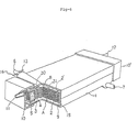
- FIG. 1 is a perspective view showing an extracapillary-flow type artificial lung which is an example of the hollow fiber fluid treating apparatus of the present invention.
- the artificial lung comprises a cylindrical housing 1 (in FIG. 1 the housing is of a square-pillar shape) and a laminate A of hollow fiber sheets each comprising a multiplicity of hollow fibers 3 formed into a cord-fabric shape through warps 4, which laminate is held with a pair of shape maintaining plates 2 and 2 each having a large opening at its center.
- the both ends of the laminate A of the hollow fiber sheets are supported and fixed liquid tight by resin partitions 5 in the housing 1.
- the hollow fibers 3 expose their open ends outwardly from the resin partitions 5.
- the resin partition 5 forms a closed blood chamber inside the housing 1.
- An outlet 6 and an inlet 7 for blood are provided on the top and the bottom walls of the housing, respectively.
- a blood outlet chamber 8 connected to the blood outlet 6, and a blood inlet chamber 9 connected to the blood inlet 7 are formed between the top wall of the housing and the top surface of the laminate and between the bottom wall of the housing and the bottom surface of the laminate, respectively.
- the ends of resin partitions 5 are each covered with head covers 10, 10'.
- On the head covers 10, 10 are mounted a gas inlet 11 and a gas outlet 12.
- the head cover 10 of the gas outlet 12 side is not always necessary. When it is not present, the gas is directly discharged into atmosphere from the open ends of the hollow fibers embedded in the resin partition 5.
- 13 is a gas vent for removing bubbles contained in blood.
- 16 is an insert for a temperature sensor.
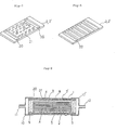
- the laminate A of hollow fiber sheets of cord-fabric type which is to be housed in a square-pillar shape housing 1, may for example be made, as shown in FIG. 2 by reciprocally folding up an endless hollow fiber sheet formed by connecting with warps 4 a multiplicity of parallely arranged single hollow fibers or bundles of a plurality of hollow fibers 20 (FIG. 2 shows the case of single hollow fibers) into cord-fabric shape, or by laminating a plurality of hollow fiber sheets previously cut to a prescribed shape one upon another.
- hollow fiber sheets are laminated one upon another, it is preferred to laminate the hollow fiber sheets in such a manner that every sheet is placed obliquely relative to the next sheet as shown in FIGURE 4, so that the upper and lower hollow fibers or bundles of a plurality of hollow fibers 20 will cross each other at an angle, whereby channeling of blood is improved.
- they for the purpose of forming a sheet from a multiplicity of parallel single hollow fibers or bundles of a plurality of hollow fibers, they, as wefts, may be woven with warps, or be adhesive-bonded to warps but, the former is preferred since it is easier.
- FIGS. 3 (a), (b), (c) and (d) show cross-sectional views of hollow fiber sheets woven into a cord-fabric shape;
- FIGS. 3 (a), (b) and (d) show ones utilizing a single hollow fiber 3 and
- FIG. 3 (c) shows another one utilizing a bundle 20 of three hollow fibers 3.
- Hollow fibers may be woven with warps into a cord fabric by any weaving method, e.g. a method comprising a warp each forming a loop around each single hollow fiber or bundle of a plurality of hollow fibers to thereby fix the single hollow fibers or bundles of a plurality of hollow fibers, e.g. chain stitch, as shown in FIGS.
- FIG. 5 shows a laminate A of the hollow fiber sheets. The top and bottom surfaces of the laminate are held between a pair of shape maintaining plates 2 and 2 each having a large opening at its central part.
- the openings of the hollow fibers at the both ends of the laminate are sealed with resin 14 and the hollow fibers are united integrally with the shape maintaining plates 2 and 2'.
- the laminate is, while being held between a pair of the shape maintaining plates 2 and 2', housed in the housing.
- the shape maintaining plates may be demounted from the laminate when it is housed in the housing. In this case the shape of the laminate of the hollow fiber sheets is well maintained since its both ends are fixed with the resin.
- hollow fiber 3 there are no specific restrictions as to the hollow fiber 3 to be formed into a sheet by the use of warps 4, insofar as the fiber has a high gas permeability; and there can be employed hollow fibers of a microporous membrane comprising a polyolefin such as polyethylene or polypropylene, polytetrafluoroethylene, polysulfones, or the like; or of a homogenous membrane comprising silicone rubber, or the like.
- a polyolefin such as polyethylene or polypropylene, polytetrafluoroethylene, polysulfones, or the like
- silicone rubber or the like.
- hollow fibers comprising polyolefins, since such fibers will not, even when their membrane thick ness is small, undergo buckling or deform when formed into a cord fabric.
- a hollow fiber comprising poly-4-methylpentene-1 because of its high gas permeability and low complement activation, as well as high affinity to blood.
- the hollow fiber to be formed into a cord-fabric shape according to the present invention generally has an outer diameter, D, of 50 to 2,000mm and a membrane thickness of 3 to 500 um. With an outer diameter or membrane thickness smaller than the above specified range the fiber may tend to snap or crack in the course of formation into a cord-fabric shape while too large an outer diameter or membrane thickness may not give a compact artificial lung suited for practical use.
- a hollow fiber having an outer diameter, D, of 100 to 500am and a membrane thickness of 6 to 100u.m.
- the effective length of the hollow fiber is generally 3 to 30 cm. If the effective length is smaller than the lower limit, the breakage loss of the fiber during fabrication of artificial lungs may be too large. On the other hand if the effective length is too large, a compact artificial lung may be difficult to realize.
- a hollow fiber or a bundle of a plurality of hollow fibers constitutes a unit weft, a multiplicity of which are then formed into a cord fabric.
- a bundle of a plurality of hollow fibers constitutes a weft preferably used is a bundle comprising not more than 35 pieces, more preferably not more than 24 pieces of hollow fibers.
- individual hollow fibers in the bundle may not fully contact with blood, whereby the gas exchange efficiency will decrease, which is not preferred.
- a single hollow fiber serves as a weft for forming a sheet of cord-fabric type.
- any fine yarn having a high tensile strength made for example of polyesters, polyamides, polyimides, polyacrylonitrile, polypropylene, polyarylates, polyvinyl alcohol, etc.
- Preferably used among the above are multifilament yarns of polyesters or polyamides having a yarn fineness of 10 to 150 deniers, more preferably 25 to 75 deniers, since they have good processability and will damage the hollow fiber only little due to their appropriate flexibility and mechanical strength.
- finishing agent to the warp should generally be avoided if possible since the product is to be used for artificial lungs. Where it is unavoidable, the finishing agent must be one having already been given safey clearance or removable by washing.
- the housing containing the laminate is, while both open ends of the hollow fibers have previously been sealed with a high-viscosity resin, immediately mounted on a centrifugal bonder. Then, a polyurethane, silicon, epoxy or the like resin is injected into the both end parts of the housing and cured there to a prescribed extent, and the both extreme ends of the resin are cut to thereby open the both ends of the hollow fiber.
- a high gas exchanging ability is achieved by specifying the shape of a hollow fiber sheet and the conditions for laminating the hollow fiber sheets.
- One of the conditions, the density, W (pieces;cm), of the warps of the hollow fiber sheet of cord-fabric type must be 0.2 W ⁇ 4.0 for the purpose of yielding with a high reproducibility an artificial lung having a high material exchanging ability, causing no stagnation or channeling of blood, and at the same time having low pressure loss and low priming volume.
- the warp density, W is less than 0.2
- the length of hollow fibers held between a pair of warps is large to thereby often cause slackening of the hollow fibers. Consequently, it will be difficult to control to arrange the hollow fibers parallel with each other at substantially constant intervals.
- the hollow fibers are thus be distributed unevenly, a larger volume of fluid flows through spaces where smaller number of hollow fibers are present caused by the slackening, thereby rendering a high gas exchanging ability impossible to achieve.
- the hollow fibers are controlled to be parallel with each other and at a very uniform distance and the volume of flow through clearances will therefore be even.
- the area of contact between the warps and the hollow fibers increases, and the area of contact between the hollow fibers and blood, i.e. effective membrane area, decreases, and further since the blood cannot flow smoothly at the parts where the warps contact the hollow fibers (crossings) there occur a decrease in the material exchanging ability and an increase in the pressure loss.
- the thickness, T, in cm of the laminate of the hollow fiber sheets be: 0.5 ⁇ T 12.0.
- the thickness of a laminate of hollow fiber sheets particularly influences the pressure loss, a thickness exceeding the above range will cause too much pressure loss rendering a pulsation-type pump difficult to use, and on the other hand too small a thickness will render the laminate too thin, whereby the nalding of the apparatus becomes complex at the time of deaeration at priming, allocation with or connectability to an artificial heart-lung apparatus, or the like.
- the hollow fiber sheets formed into a cord-fabric shape as described above are then laminated one upon another in a prescribed number of sheets and the laminate is then housed in a housing.
- the laminate may be placed in the housing as it is if the laminate can maintain its shape in the housing, and if not (e.g. as a result of the hollow fibers vi brating caused by pressure of blood whereby channeling occurs resulting in a decrease in the gas exchanging ability), the laminate should be provided on either one of the top and bottom surfaces thereof with a shape maintaining plate for holding the shape of the laminate. Whether the laminate of the hollow fiber sheets can maintain its shape in the housing or not can readily judged in the following manner:
- clearances between the laminate of hollow fiber sheets housed in a housing and the side walls of the housing might cause blood to bypass through the clearances to thereby decrease the gas exchanging ability.
- a sealing means 15 such as polyurethane, silicone, epoxy or the like resin, or by patching a thermoplastic film or the like on the both sides of the laminate, followed by fixing the film on the side walls of the housing.
- the laminate of the hollow fiber sheets can maintain its shape without the provision of any shape maintaining plate 2 or 2'.
- FIG. 6 shows an example of an artificial lung comprising a laminate A of hollow fiber sheets provided on the top and bottom surfaces thereof with a pair of shape maintaining plates 2 and 2 each having a plurality of openings.
- Perforated plates may be used as the shape maintaining plates 2 and 2' but, it is preferred for the purpose of preventing blood from stagnation to use, as shown in FIG. 7, to use a pair of plates 2 and 2' having a pair of large openings 30 at the parts contacting the resin partitions 5 on which the both ends of the laminate of hollow fiber sheets are fixed by adhesion, and a multiplicity of small openings 31 between the two large openings 30.
- Also may be used as having a function of preventing blood from stagnation is a plate having a plurality of large openings 32 as shown in FIG. 8.
- the ratio of the area of openings to the total area contacting blood i.e. the opening ratio of the shape maintaining plate 2 or 2 is preferably at least 10%, more preferably at least 30%. In the case where the opening ratio is less than 10%, stagnation of blood may occur between neighboring openings causing thrombi and it is difficult to achieve a high gas exchanging ability per unit membrane area.
- FIG. 9 is a cross-sectional view of the artificial lung shown in FIG. 6.
- the blood flows smoothly, without causing stagnation, through an opening 30 provided on the shape maintaining plates 2 and 2', as shown by the arrow.
- the shape maintaining plate 2 or 2 is a plate having a rigidity that will not allow the plate to deform by force of blood flow, made of a polyolefin such as polyethylene or polypropylene, polystyrene, polyacrylates, polyamides, polycarbonates, thin metal plates or the like. Generally used preferably are resin plates having a thickness of 0.5 to 5 mm, made of a polycarbonate, polyamide, or a polyolefin.
- the apparatus of the present invention may be used as an artificial lung as consolidated with a heat exchanger such as piping of stainless steel, aluminum or the like metals mounted in the blood inlet chamber 9 or blood outlet chamber 8 formed in the housing.
- a heat exchanger such as piping of stainless steel, aluminum or the like metals mounted in the blood inlet chamber 9 or blood outlet chamber 8 formed in the housing.
- FIG. 10 is an example of the artificial lung comprising a heat exchanger mounted in the blood chamber, in which a multiplicity of pipes 26 for heat exchanging are mounted in the blood inlet chamber 9 parallel with hollow fibers 3, both ends of the pipes being provided with head covers 19 and 19 having an inlet 17 and an outlet 18 for heating medium.
- FIG. 11 shows an example of the artificial lung comprising a laminate A of hollow fiber sheets housed in a cylindrical housing 40.
- the laminate A of the hollow fiber sheets is obtained by, as shown in FIG. 12, wrapping an endless hollow fiber sheet of cord-fabric type around an aperture inner cylinder 42, then covering the wrap with a pair of half-split outer cylinders, and bonding the joints of the two outer half- cylinders by ultrasonic bonding to thereby complete a consolidated outer cylinder 43, whereby the laminate can maintain its shape.
- the laminate A of the hollow fiber sheets housed between the apertured inner cylinder 42 and the outer cylinder 43 is supported and fixed with partitions 44 and 44 sealing the both ends of the housing such that the both ends are kept open outwardly.
- the top end of the cylindrical housing 40 is covered with a top head cover 50 having a gas inlet 45 and a blood inlet 46 connected with the inside of the apertured inner cylinder 42.
- the bottom end of the housing is covered with a bottom head cover 48 having a gas outlet 47 connecting with internal spaces of the hollow fibers.
- the cylindrical housing 40 is provided on its upper side wall with a blood outlet 49.
- the tip of the blood inlet 46 penetrates the upper partition 44 and opens into the inside of the apertured inner cylinder 42.
- the blood introduced from the inlet 46 into the inside of the apertured inner cylinder 42 flows through the holes on the apertured inner cylinder into the gas exchange chamber, and then flows radially in the gas exchange chamber outwardly to finally discharge through blood outlet 49 provided on the upper wall of the cylindrical housing 40.
- the gas introduced from gas inlet 45 into the inside of hollow fibers flow downwardly to the lower part of the cylindrical housing.
- the fluid treating apparatus of hollow fiber type of the present invention can be used for, in addition to the above-described artificial lung, treating many other fluids.
- it can be used for dialysis which comprises conducting mass transfer between two kinds of liquids via the hollow fiber.
- two liquids may either flow inside or outside the hollow fiber but, it is generally preferred that the liquid containing substance(s) to be dialyzed flows inside the hollow fiber.
- the apparatus of the present invention can also be used for gas exchange which comprises conducting mass transfer between a gas and a liquid via hollow fiber to thereby dissolve the gas in the liquid or discharge the gas. In this case it is preferred that the gas flows inside the hollow fiber while the liquid flows outside.
- the apparatus can be used for conducting mass transfer via hollow fiber between two kinds of gases or for filtering or condensing a gas or liquid by separating a specific substance(s) contained therein.
- the apparatus can be used for conducting mass transfer via hollow fiber between two kinds of gases or for filtering or condensing a gas or liquid by separating a specific substance(s) contained therein.
- either one of the two kinds of gases or the gas and liquid may flow inside the hollow fiber.
- a plurality of microporous polypropylene hollow fibers each having an outer diameter of 360 L L, an inner diameter of 28OLL and a porosity of about 50% are arranged parallel with each other in a density in the longitudinal direction, F, of 17 pieces/cm, and woven into a cord-fabric shape using as the warp a polyester yarn of 30 deniers/12 filaments in a warp density in the transversal direction, W, of 1 piece/cm.
- the thus prepared hollow fiber sheet was, as shown in FIG. 2, folded into a laminate having a number of sheets per unit thickness, I, of 30 sheets/cm, a width of 8 cm and a thickness, T, of 4 cm.
- the (F x I) of the thus obtained laminate was 510 and the effective membrane area was 1.58 m 2.
- the laminate was then held between a pair of apertured polypropylene plates of a thickness of 3.5 mm and with a multiplicity of holes each having a diameter of 2 mm and located at 8-mm intervals as well as a pair of larger openings at the both ends thereof having a width of 20 mm as shown in FIG. 7, and the obtained unit was housed in a square-pillar shape housing.
- the two ends of the hollow fiber sheets were bonded liquid tight with a pair of polyurethane partitions to the housing, and then a resin was filled into the clearances formed between the both sides of the laminate and the side walls of the housing, to prepare an arificial lung as shown in FIG. 6.
- the thus obtained artificial lung was tested according to "DRAFT OF EVALUATION STANDARD FOR ARTIFICIAL LUNG PERFORMANCE" (Japan Artificial Organs Association) by flowing bovine blood warmed to a temperature of 37° C and pure oxygen gas while the ratio of oxygen flow rate to the blood flow rate was maintained at 1.0.
- the maximum blood flow rate, the pressure loss and the P 50 /T ⁇ I ⁇ n were 7,300 ml/min/m 2 , 105 mmHg and 0.365 respectively, proving the extremely high gas exchanging ability of the artificial lung tested as compared to those of conventional ones.
- a maximum blood flow rate of not more than 2,000 ml/min/m 2 or a pressure loss at a blood flow rate of 6 I/min of not less than 300 mmHg has some problem in practice, and hence marked * at the right end of the column.
- Pluralities of the hollow fibers shown in Test 1 were bundled. Groups of the bundles were each arranged in different longitudinal densities and woven into a hollow fiber sheet in the same manner as in Experiment 1.
- Four laminates were prepared from the sheets with different number of sheets laminated, I's, to be of the same thickness of 4 cm.
- Four artificial lungs similar to those in Experiment 1 were obtained using the laminates and evaluated in the same manner as in Experiment 1. The results are shown in Table 4.
- a hollow fiber of a microporous polypropylene hollow fiber having outer and inner diameters of 250u. and 210 ⁇ respectively and a porosity of about 50% was used to prepare a hollow fiber sheet in which single filaments of the hollow fiber were arranged as wefts and woven with warps.
- Four kinds of laminates were obtained using the above-prepared sheet with parameters shown in Table 5, and corresponding artificial lungs were prepared from the laminates and evaluated in the same manner as in Experiment 1. The results are shown in Table 5.
- a hollow fiber sheet was formed by arranging parallel a multiplicity of microporous polyvinyl alcohol hollow fibers having outer an inner diameters of 510 ⁇ and 320u. respectively and a porosity of about 50% in a density in the longitudinal direction, F, of 14 pieces/cm as wefts and woven with warps of polyester yarn of 30 deniers/12 filaments in a warp density, W, of 1 piece/cm into a cord fabric.
- the thus obtained endless sheet was folded reciprocally to form a laminate of the hollow fiber sheets having a number of sheets laminated, I, of 22 sheets/cm, a width of 6 cm and a thickness, T, of n4 cm.
- the laminate was then held between a pair of the plates shown in FIG. 7 and the obtained unit was housed in a housing to give an apparatus as shown in FIG. 6.
- the then effective length was 7 cm.
- the (F x I) and the effective membrane area of the obtained laminate were 308 and 0.52 m 2 respectively.
- bovine blood warmed up to 37° C was flown outside, extracapillarily, the hollow fibers at a blood flow rate of 100 ml/min.
- the flow rate of the inside filtrate was stepwise increased.
- the maximum flow rate filtered, QFmax, just before a sharp rise of the pressure difference via the membrane in 30 minutes was 42.5 ml/min and the A P 50 T ⁇ I ⁇ n was 0.716, proving a higher flow rate achieved as compared to that conventional apparatuses.
- a hollow fiber sheet was formed by arranging parallel a multiplicity of ethylene-vinyl alcohol copolymer hollow fibers having an outer and inner diameters of 225u. and 175u. respectively in a density in the longitudinal direction, F, of 24 pieces/cm as wefts and woven with warps of polyester yarn of 30 deniers/12 filaments in a warp density, W, of 1 piece/cm into a cord fabric.
- the thus prepared endless sheet was folded reciprocally to form a laminate of the hollow fiber sheets having a number of sheets laminated, I, of 45 sheets/cm, a width of 6 cm and a thickness, T, of 4 cm.
- the laminate was then, in the same manner as in Experiment 23, held between a pair of plates and the obtained unit was housed in a housing to give an apparatus as shown in FIG. 6.
- the F x I and the effective membrane area of the laminate were 1080 and 1.14 m 2 , respectively and the effective length of the hollow fiber was 8 cm.
- the apparatus was tested while bovine blood warmed to 37° C was flown inside the hollow fibers and the dialysate outside according to ARTIFICIAL KIDNEY EVLUATION STANDARD made by Japan Artificial Organs Association to give a clearance of urea and ⁇ P 50 /T ⁇ I ⁇ n of 157 ml/min and 0.533 respectively.
- a hollow fiber sheet was formed by arranging parallel a multiplicity of microporous poly-4-methylpentene-1 hollow fibers having outer and inner diameters of 260u. and 210u. respectively in a density in the longitudinal direction, F, of 22 pieces/cm as wefts and woven with warps of polyester yarn of 30 deniers/12 filaments in a warp density, W, of 1 piece/cm into a cord fabric.
- the thus prepared endless sheet was folded reciprocally to form a laminate of the hollow fiber sheets having a number of sheets laminated, I, of 36 sheets/cm, a width of 4 cm and a thickness, T, of 3 cm.
- the F x I of the laminate was 792 and the effective length and the effective membrane area of the hollow fiber were 4 cm and 0.22 m 2 respectively.
- the laminate was then housed in a housing, then the both sides of the laminate were bonded with a polyurethane resin liquid tight to the housing, and the clearances 9 then formed between the both sides of the laminate of the hollow fiber sheets and the side walls of the housing were filled with a resin to give an apparatus as shown in FIG. 1.
- the apparatus was tested in the same way as in Experiment 1. Then, the maximum blood flow rate was 5,500 ml/min/m 2 , and the pressure loss and the ⁇ P 50 /T ⁇ I ⁇ n were 45 mmHg and 0.278 respectively.
- a hollow fiber sheet was formed by arranging parallel a multiplicity of microporous polypropylene hollow fibers having outer and inner diameters of 360 ⁇ and 280 ⁇ respectively and a porosity of about 50% in a density in the longitudinal direction, F, of 17 pieces/cm as wefts and woven with warps of polyester yarn of 30 deniers/12 filaments in a warp density, W, of 1 piece/cm into a cord fabric.
- a laminate of the hollow fiber sheets was obtained by wrapping the hollow fiber sheet of cord-fabric type around an apertured polypropylene inner cylinder with a diameter and a thickness of 2 cm and 2.5 mm respectively having a multiplicity of holes each having a diameter of 3 mm and spaced at 8-mm intervals, to a thickness of the laminate, T, of 3 cm, a laminate of the hollow fibre sheets having a number of sheets laminated, I of 30 sheets/cm, then covering the wrap with a pair of half-split outer apertured polypropylene cylinders with a diameter and a thickness of 8.5 cm and 2.5 mm respectively having a a multiplicity of holes each having a diameter of 3 mm and spaced at 8-mm intervals, and bonding the joints of the two outer half- cylinders by ultrasonic bonding to thereby complete consolidated outer cylinder, which maintained the laminate of the hollow fiber sheets.
- the F x I and the effective membrane area of the laminate were 510 and 1.48 m 2 respectively.
- the laminate unit was housed in a cylindrical housing having a diameter and a thickness of 10 cm and 2.5 mm respectively.
- the two ends of the hollow fibers were held with a pair of polyurethane partitions formed at the both ends of the housing to complete an apparatus as shown in FIG. 11.
- the apparatus was tested in the same way as in Experiment 1 to give a maximum blood flow rate, a pressure loss and a ⁇ P 50 %T ⁇ I ⁇ n of 6,500 ml/min/m 2 , 85 mmHg and 0.232 respectively.
Abstract
Description
- This invention relates to a fluid treatment apparatus utilizing a hollow fiber, for example to an apparatus suitable for treating blood.
- Fluid treatment apparatus using hollow fibres is generally, but not exclusively, used for blood dialyzers, artificial lungs, plasma separators, humidifiers and the like. For convenience, we refer herein to apparatus used in an artificial lung but it is not intended that the invention should be limited to such use.
- Artificial lungs have a gas exchanging function which can add oxygen to and remove carbon dioxide from human blood, which function is one of the functions exhibited by the human lung. Bubble-type artificial lungs and membrane-type ones are currently in use.
- The bubble-type artificial lung has had wide clinical use. It however has been found that with this system hemolysis, protein degeneration, blood clotting and minute thrombi, or activation of leukocytes or complements, tends to occur and defoaming effect weakens over long-period use to thereby cause minute bubbles to invade into the blood.
- The membrane-type artificial lung causes contact of the blood with a gas via a membrane between the two to absorb oxygen into the blood and at the same time discharge carbon dioxide from the gas. The apparatus has advantages of smaller blood damage and smaller priming volume compared to those with the bubble type and has hence gradually been used instead of the bubble type.
- The membrane-type artificial lungs so far developed conduct gas exchange via a hollow fiber membrane by using a microporous hollow fiber made of a hydrophobic polymer such as polyolefin or a homogeneous hollow fiber of a material having a gas permeable such as silicone. They consist of two types, i.e. the intracapillary flow type wherein blood flows inside a hollow fiber while a gas flows outside the hollow fiber (cf. Japanese Patent Application Laid-Open Nos. 106770/1987, 57661/1984, etc.), and the extracapillary flow type wherein gas flows inside a hollow fiber and blood flows outside the hollow fiber (cf. Japanese Patent Application Laid-Open Nos. 57963/1984, 28806/1985, etc.).
- In the intracapillary-flow type artificial lungs, when the blood is uniformly distributed inside a multiplicity of hollow fibers, blood flow inside the hollow fiber is substantially laminar through there occurs no channeling (biassed flow) of the blood. The inner diameter of the hollow fiber therefore is required to be small to increase the gas exchanging ability (gas transfer rate per unit area of membrane), and hollow fibers having an inner diameter of 150 to 300 u.m have been developed.
- However, even with a small inner diameter, the gas exchanging ability cannot be greatly increased since the blood flows in a laminar flow. Therefore, an intracapillary-flow type artificial lung requires a membrane area as large as about 6 m2 for achieving a gas exchanging ability of 200 to 300 cc/min which is necessary e.g. when open heart surgery is conducted on an adult. The apparatus is thus large and heavy and hence difficult to handle. Furthermore, they have a large priming volume which also increases the burden on a patient. If the inner diameter is made still smaller to make the artificial lung more compact to improve handling, there will occur frequent clotting (clogging of the inside of hollow fibers due to blood clotting). Besides, artificial lungs of this type cannot conduct flow by gravity due to the large resistance in the blood passage, and are hence difficult for use with a blood pump of the pulsation flow type.
- In artificial lungs, if the gas is supplied is not uniformly distributed, the carbon dioxide removing ability (transfer rate of carbon dioxide per unit area of membrane) will decrease. It is difficult to distribute and supply the gas sufficiently uniformly to several thousands to several tens of thousands of hollow fibers. Special designs therefore are necessary for supplying the gas uniformly to a multiplicity of hollow fibers.
- On the other hand, in extracapillary-flow type artificial lungs, it is expected that the gas be more uniformly distributed and the blood flow have some disturbance therein. However, it has been found that shortage of oxygenation tends to occur as a result of channeling of blood flow or blood clotting due to stagnation of blood flow. Commercially available extracapillary-flow type artificial lungs have a problem that a large membrane area is required for compensating for the shorgate of oxygenation due to channeling of blood fow, and this results in a large priming volume. where an artificial lung is used for a patient having a small amount of blood, blood transfusion therefore is required, which in turn leads to the danger of the patient catching hepatis, AIDS or the like.
- The present inventors have studied extracapillary-flow type artificial lungs, which suffer little pressure loss and have high gas exchanging ability per unit area, and tried to eliminate their drawbacks, i.e. channeling and/or stagnation of blood flow, by the use of a sheet of cord-fabric-like type comprising a multiplicity of hollow fibers connected by warps. However, it then was found that simply placing a laminate a sheets of hollow fibers connected with warps in the form of cord-fabric-like type in a housing would increase, contrary to the inventors' expectation, channeling of blood and decrease the gas exchanging ability per unit membrane area.
- However, by controlling the parameters of the laminate we have now been able to provide a compact fluid treating apparatus, for example an artificial lung, which avoids stagnation or channeling of blood and which exhibits a small pressure drop.
- Thus, we have found that blood channeling had been caused by the fact that the openings of the hollow fiber sheets formed by individual hollow fibers and the warps deform under the blood flow. The inventors have further studied how to laminate the hollow fiber sheets to minimize such deformation
- Thus, in accordance with the invention there is provided a fluid treating apparatus of the hollow fiber type which comprises a laminate of hollow fiber sheets comprising a multiplicity of single hollow fibers or bundles of hollow fibers connected by warps, said laminate being housed in a housing having an inlet and an outlet for a first fluid which inlet and outlet connect with the space defined by the hollow fibers and the housing, and an inlet and an outlet for a second fluid which inlet and outlet connect with the insides of the hollow fibers, two ends of the laminated hollow fiber sheets being embedded in partitions and held liquid tight in the housing, and wherein the following formulae are satisfied:
-
- 0.2 ≦ W 4.0
- 0.5 ≦T≦ 12.0
- 108 /(3.0 x D)2 F x I < 108.1(0.93 x D)2
- wherein:
- D is the diameter in mm of a hollow fiber or a bundle of hollow fibers,
- W is the warp density in pieces per cm of the warps connecting a multiplicity of single hollow fibers or bundles of hollow fibers,
- F is the density in pieces per cm of single hollow fibers or bundles of a plurality of hollow fibers per unit length of the hollow fiber sheet,
- I is the number of hollow fiber sheets laminated per unit thickness in sheets per cm, and
- T is the thickness in cm of the laminate of the hollow fiber sheets.
- Preferred features and embodiments of the invention are described below by way of example and with reference to the accompanying drawings, in which:-
- FIG. 1 is a partially cutaway perspective view of an embodiment of fluid treating apparatus of hollow fiber type according to the present invention;
- FIG. 2 is a perspective view showing an example of how hollow fiber sheets may be laminated;
- FIG. 3 (a), (b), (c) and (d) are cross-sectional views of hollow fiber sheets;
- FIG. 4 is a plan showing another example of how hollow fiber sheets may be laminated;
- FIG. 5 is a perspective view of an example of a laminate of hollow fiber sheets;
- FIG. 6 is a perspective view of another example of a laminate of hollow fiber sheets;
- FIGS. 7 and 8 are perspective views of shape maintaining plates for holding a laminate of hollow fiber sheets;
- FIG. 9 is a cross-sectional view of apparatus comprising the laminate shown in FIG. 5 housed therein;
- FIG. 10 is a perspective view of an apparatus comprising a heat exchanger housed in the space formed by a laminate of hollow fiber sheets and a housing;
- FIG. 11 is a cross-sectional view of an apparatus utilizing a laminate of hollow fiber sheets formed cylindrically; and
- FIG. 12 is a cross-sectional view of the apparatus of FIG. 10 taken on line A-A.
- FIG. 1 is a perspective view showing an extracapillary-flow type artificial lung which is an example of the hollow fiber fluid treating apparatus of the present invention. As shown in FIG. 1, the artificial lung comprises a cylindrical housing 1 (in FIG. 1 the housing is of a square-pillar shape) and a laminate A of hollow fiber sheets each comprising a multiplicity of
hollow fibers 3 formed into a cord-fabric shape throughwarps 4, which laminate is held with a pair ofshape maintaining plates resin partitions 5 in the housing 1. Thehollow fibers 3 expose their open ends outwardly from theresin partitions 5. Theresin partition 5 forms a closed blood chamber inside the housing 1. Anoutlet 6 and aninlet 7 for blood are provided on the top and the bottom walls of the housing, respectively. Ablood outlet chamber 8 connected to theblood outlet 6, and ablood inlet chamber 9 connected to theblood inlet 7 are formed between the top wall of the housing and the top surface of the laminate and between the bottom wall of the housing and the bottom surface of the laminate, respectively. The ends ofresin partitions 5 are each covered withhead covers 10, 10'. On the head covers 10, 10 are mounted a gas inlet 11 and agas outlet 12. Thehead cover 10 of thegas outlet 12 side is not always necessary. When it is not present, the gas is directly discharged into atmosphere from the open ends of the hollow fibers embedded in theresin partition 5. 13 is a gas vent for removing bubbles contained in blood. 16 is an insert for a temperature sensor. - In the above-described hollow fiber artificial lung, the laminate A of hollow fiber sheets of cord-fabric type, which is to be housed in a square-pillar shape housing 1, may for example be made, as shown in FIG. 2 by reciprocally folding up an endless hollow fiber sheet formed by connecting with warps 4 a multiplicity of parallely arranged single hollow fibers or bundles of a plurality of hollow fibers 20 (FIG. 2 shows the case of single hollow fibers) into cord-fabric shape, or by laminating a plurality of hollow fiber sheets previously cut to a prescribed shape one upon another. Where the hollow fiber sheets are laminated one upon another, it is preferred to laminate the hollow fiber sheets in such a manner that every sheet is placed obliquely relative to the next sheet as shown in FIGURE 4, so that the upper and lower hollow fibers or bundles of a plurality of
hollow fibers 20 will cross each other at an angle, whereby channeling of blood is improved. For the purpose of forming a sheet from a multiplicity of parallel single hollow fibers or bundles of a plurality of hollow fibers, they, as wefts, may be woven with warps, or be adhesive-bonded to warps but, the former is preferred since it is easier. - FIGS. 3 (a), (b), (c) and (d) show cross-sectional views of hollow fiber sheets woven into a cord-fabric shape; FIGS. 3 (a), (b) and (d) show ones utilizing a single
hollow fiber 3 and FIG. 3 (c) shows another one utilizing abundle 20 of threehollow fibers 3. Hollow fibers may be woven with warps into a cord fabric by any weaving method, e.g. a method comprising a warp each forming a loop around each single hollow fiber or bundle of a plurality of hollow fibers to thereby fix the single hollow fibers or bundles of a plurality of hollow fibers, e.g. chain stitch, as shown in FIGS. 3 (a) and 3 (c); a method which comprises a pair each of warps fixing each single hollow fiber or bundle of hollow fibers as shown in FIGS. 3 (b) and (d), e.g. "leno" weaving; or the like. The method of fixing each single hollow fiber or bundle of a plurality of hollow fibers by forming a loop with a warp each as shown in FIGS. 3 (a) and (c) is preferred since such method assures no sliding of the hollow fibers while keeping constant the clearance between the neighboring hollow fibers. FIG. 5 shows a laminate A of the hollow fiber sheets. The top and bottom surfaces of the laminate are held between a pair ofshape maintaining plates resin 14 and the hollow fibers are united integrally with theshape maintaining plates 2 and 2'. The laminate is, while being held between a pair of theshape maintaining plates 2 and 2', housed in the housing. In the case where the ratio of the length to the width of the laminate is small, the shape maintaining plates may be demounted from the laminate when it is housed in the housing. In this case the shape of the laminate of the hollow fiber sheets is well maintained since its both ends are fixed with the resin. - There are no specific restrictions as to the
hollow fiber 3 to be formed into a sheet by the use ofwarps 4, insofar as the fiber has a high gas permeability; and there can be employed hollow fibers of a microporous membrane comprising a polyolefin such as polyethylene or polypropylene, polytetrafluoroethylene, polysulfones, or the like; or of a homogenous membrane comprising silicone rubber, or the like. - Preferred are hollow fibers comprising polyolefins, since such fibers will not, even when their membrane thick ness is small, undergo buckling or deform when formed into a cord fabric. Particularly preferred is a hollow fiber comprising poly-4-methylpentene-1 because of its high gas permeability and low complement activation, as well as high affinity to blood.
- The hollow fiber to be formed into a cord-fabric shape according to the present invention generally has an outer diameter, D, of 50 to 2,000mm and a membrane thickness of 3 to 500 um. With an outer diameter or membrane thickness smaller than the above specified range the fiber may tend to snap or crack in the course of formation into a cord-fabric shape while too large an outer diameter or membrane thickness may not give a compact artificial lung suited for practical use. In general, preferred is a hollow fiber having an outer diameter, D, of 100 to 500am and a membrane thickness of 6 to 100u.m.
- The effective length of the hollow fiber is generally 3 to 30 cm. If the effective length is smaller than the lower limit, the breakage loss of the fiber during fabrication of artificial lungs may be too large. On the other hand if the effective length is too large, a compact artificial lung may be difficult to realize.
- A hollow fiber or a bundle of a plurality of hollow fibers constitutes a unit weft, a multiplicity of which are then formed into a cord fabric. where a bundle of a plurality of hollow fibers constitutes a weft, preferably used is a bundle comprising not more than 35 pieces, more preferably not more than 24 pieces of hollow fibers. In a bundle comprising more than 35 pieces of hollow fibers, individual hollow fibers in the bundle may not fully contact with blood, whereby the gas exchange efficiency will decrease, which is not preferred. Generally, a single hollow fiber serves as a weft for forming a sheet of cord-fabric type. In this case, not only almost 100% of the surface area of each hollow fiber is used for gas exchange, but an unexpectedly high gas exchange performance is achieved with a relatively small membrane area and the pressure loss is small. The reason is believed to be that distribution and mixing of blood in minute units can be done extremely efficiently thanks to the formation of uniform rectangular slits defined by the warp and the weft.
- There are no particular restrictions as to the type of the warp for forming the hollow fiber into a cord fabric and there may conveniently be used any fine yarn having a high tensile strength made for example of polyesters, polyamides, polyimides, polyacrylonitrile, polypropylene, polyarylates, polyvinyl alcohol, etc. Preferably used among the above are multifilament yarns of polyesters or polyamides having a yarn fineness of 10 to 150 deniers, more preferably 25 to 75 deniers, since they have good processability and will damage the hollow fiber only little due to their appropriate flexibility and mechanical strength.
- Application of any finishing agent to the warp should generally be avoided if possible since the product is to be used for artificial lungs. Where it is unavoidable, the finishing agent must be one having already been given safey clearance or removable by washing.
- The housing containing the laminate is, while both open ends of the hollow fibers have previously been sealed with a high-viscosity resin, immediately mounted on a centrifugal bonder. Then, a polyurethane, silicon, epoxy or the like resin is injected into the both end parts of the housing and cured there to a prescribed extent, and the both extreme ends of the resin are cut to thereby open the both ends of the hollow fiber.
- In the present invention, a high gas exchanging ability is achieved by specifying the shape of a hollow fiber sheet and the conditions for laminating the hollow fiber sheets. One of the conditions, the density, W (pieces;cm), of the warps of the hollow fiber sheet of cord-fabric type must be
0.2 W≤ 4.0
for the purpose of yielding with a high reproducibility an artificial lung having a high material exchanging ability, causing no stagnation or channeling of blood, and at the same time having low pressure loss and low priming volume. - Where the warp density, W, is less than 0.2, the length of hollow fibers held between a pair of warps is large to thereby often cause slackening of the hollow fibers. Consequently, it will be difficult to control to arrange the hollow fibers parallel with each other at substantially constant intervals. When the hollow fibers are thus be distributed unevenly, a larger volume of fluid flows through spaces where smaller number of hollow fibers are present caused by the slackening, thereby rendering a high gas exchanging ability impossible to achieve.
- Where the warp density, W, is larger than 4.0, the hollow fibers are controlled to be parallel with each other and at a very uniform distance and the volume of flow through clearances will therefore be even. However, as the warp density increases, the area of contact between the warps and the hollow fibers increases, and the area of contact between the hollow fibers and blood, i.e. effective membrane area, decreases, and further since the blood cannot flow smoothly at the parts where the warps contact the hollow fibers (crossings) there occur a decrease in the material exchanging ability and an increase in the pressure loss.
- As regards the density, F (pieces/cm), of the hollow fibers, which are wefts, along a longitudinal unit length and the number of the hollow fiber sheets laminated per unit thickness, I (sheets/cm), with increasing F and/or I the gas exchanging ability of the artificial lung clearly increases but the pressure loss of the blood side increases at the same time. For the purpose of realizing an artificial lung having a high gas exchange ability with low pressure loss the following relationship therefore must be assured:
108/(3.0 x D)2 F x I < 1081(0.93 x D)2
wherein where the weft of a cord-fabric sheet is a single hollow fiber, D represents the outer diameter in µm of the hollow fiber; and where the weft is a bundle of a plurality of hollow fibers, D represents the outer diameter in u.m of a hypothetical cylinder closest-packed with the plurality of the hollow fibers but without causing their collapse. - If (F x I) is smaller than the above range, the material exchanging ability will be small; and if (F x I) exceeds the above range, a large pressure loss will be encountered.
- Another requirement of the present invention is that the thickness, T, in cm of the laminate of the hollow fiber sheets be:
0.5 ≦T 12.0.
Whereas the thickness of a laminate of hollow fiber sheets particularly influences the pressure loss, a thickness exceeding the above range will cause too much pressure loss rendering a pulsation-type pump difficult to use, and on the other hand too small a thickness will render the laminate too thin, whereby the nalding of the apparatus becomes complex at the time of deaeration at priming, allocation with or connectability to an artificial heart-lung apparatus, or the like. - The hollow fiber sheets formed into a cord-fabric shape as described above are then laminated one upon another in a prescribed number of sheets and the laminate is then housed in a housing. If appropriate, the laminate may be placed in the housing as it is if the laminate can maintain its shape in the housing, and if not (e.g. as a result of the hollow fibers vi brating caused by pressure of blood whereby channeling occurs resulting in a decrease in the gas exchanging ability), the laminate should be provided on either one of the top and bottom surfaces thereof with a shape maintaining plate for holding the shape of the laminate. Whether the laminate of the hollow fiber sheets can maintain its shape in the housing or not can readily judged in the following manner:
- There is a close relationship between the laminate thickness, T (cm), the number of sheets laminated per unit thickness, I (cm), the pressure loss when the flow rate of a first fluid is 50 ml/min/cm2 A Pso - (mmHg), and the number of hollow fibers, n (pieces), constituting single hollow fiber or a bundle of a plurality of hollow fibers forming the hollow fiber sheet. As T and/or I increases, through the gas exchanging ability of the artificial lung distinctly increases, the pressure loss of the blood side at the same time increases and vibration of hollow fibers occurs to cause a decrease in the gas exchanging ability. Therefore, for the purpose of realizing an artificial lung having a high gas exchanging ability while maintaining the shape of the laminate, there must be:
ΔP50/T· I 'n 5 1.0. - If AP5o,/T * I n n is larger than the above range, the hollow fibers will suffer a too large resistance, whereby the hollow fibers tend to cause channeling or vibration forced by blood flow. Therefore in the case where ΔP50/T· I · n exceeds 1.0, it is necessary that a shape maintaining plate be provided to suppress the effect of the hollow fibers.
- In the case of square-pillar type laminate as shown in FIG. 5, formation of clearances between the laminate of hollow fiber sheets housed in a housing and the side walls of the housing might cause blood to bypass through the clearances to thereby decrease the gas exchanging ability. For the purpose of preventing such trouble, as shown in FIG. 1, the above clearances are sealed with a sealing means 15, such as polyurethane, silicone, epoxy or the like resin, or by patching a thermoplastic film or the like on the both sides of the laminate, followed by fixing the film on the side walls of the housing. Where the clearances formed between the laminate and side walls of the housing have been sealed with a sealing means and the ratio, L'D, of the effective length, L, to the width, D, of the laminate is for example not more than 2.0, the laminate of the hollow fiber sheets can maintain its shape without the provision of any
shape maintaining plate 2 or 2'. - FIG. 6 shows an example of an artificial lung comprising a laminate A of hollow fiber sheets provided on the top and bottom surfaces thereof with a pair of
shape maintaining plates shape maintaining plates 2 and 2' but, it is preferred for the purpose of preventing blood from stagnation to use, as shown in FIG. 7, to use a pair ofplates 2 and 2' having a pair oflarge openings 30 at the parts contacting theresin partitions 5 on which the both ends of the laminate of hollow fiber sheets are fixed by adhesion, and a multiplicity ofsmall openings 31 between the twolarge openings 30. Also may be used as having a function of preventing blood from stagnation is a plate having a plurality oflarge openings 32 as shown in FIG. 8. The ratio of the area of openings to the total area contacting blood, i.e. the opening ratio of theshape maintaining plate - FIG. 9 is a cross-sectional view of the artificial lung shown in FIG. 6. Here the blood flows smoothly, without causing stagnation, through an
opening 30 provided on theshape maintaining plates 2 and 2', as shown by the arrow. - The
shape maintaining plate - The apparatus of the present invention may be used as an artificial lung as consolidated with a heat exchanger such as piping of stainless steel, aluminum or the like metals mounted in the
blood inlet chamber 9 orblood outlet chamber 8 formed in the housing. - FIG. 10 is an example of the artificial lung comprising a heat exchanger mounted in the blood chamber, in which a multiplicity of
pipes 26 for heat exchanging are mounted in theblood inlet chamber 9 parallel withhollow fibers 3, both ends of the pipes being provided with head covers 19 and 19 having aninlet 17 and anoutlet 18 for heating medium. - FIG. 11 shows an example of the artificial lung comprising a laminate A of hollow fiber sheets housed in a
cylindrical housing 40. The laminate A of the hollow fiber sheets is obtained by, as shown in FIG. 12, wrapping an endless hollow fiber sheet of cord-fabric type around an apertureinner cylinder 42, then covering the wrap with a pair of half-split outer cylinders, and bonding the joints of the two outer half- cylinders by ultrasonic bonding to thereby complete a consolidatedouter cylinder 43, whereby the laminate can maintain its shape. - In FIG. 11, the laminate A of the hollow fiber sheets housed between the apertured
inner cylinder 42 and theouter cylinder 43 is supported and fixed withpartitions - The top end of the
cylindrical housing 40 is covered with atop head cover 50 having agas inlet 45 and ablood inlet 46 connected with the inside of the aperturedinner cylinder 42. The bottom end of the housing is covered with abottom head cover 48 having agas outlet 47 connecting with internal spaces of the hollow fibers. - The
cylindrical housing 40 is provided on its upper side wall with ablood outlet 49. The tip of theblood inlet 46 penetrates theupper partition 44 and opens into the inside of the aperturedinner cylinder 42. - The blood introduced from the
inlet 46 into the inside of the aperturedinner cylinder 42 flows through the holes on the apertured inner cylinder into the gas exchange chamber, and then flows radially in the gas exchange chamber outwardly to finally discharge throughblood outlet 49 provided on the upper wall of thecylindrical housing 40. The gas introduced fromgas inlet 45 into the inside of hollow fibers flow downwardly to the lower part of the cylindrical housing. - The fluid treating apparatus of hollow fiber type of the present invention can be used for, in addition to the above-described artificial lung, treating many other fluids. For example, it can be used for dialysis which comprises conducting mass transfer between two kinds of liquids via the hollow fiber. In this case, two liquids may either flow inside or outside the hollow fiber but, it is generally preferred that the liquid containing substance(s) to be dialyzed flows inside the hollow fiber. The apparatus of the present invention can also be used for gas exchange which comprises conducting mass transfer between a gas and a liquid via hollow fiber to thereby dissolve the gas in the liquid or discharge the gas. In this case it is preferred that the gas flows inside the hollow fiber while the liquid flows outside. Further, the apparatus can be used for conducting mass transfer via hollow fiber between two kinds of gases or for filtering or condensing a gas or liquid by separating a specific substance(s) contained therein. In this case either one of the two kinds of gases or the gas and liquid may flow inside the hollow fiber.
- The invention is further illustrated by way of non-limiting example with reference to the following experiments:-
- A plurality of microporous polypropylene hollow fibers each having an outer diameter of 360LL, an inner diameter of 28OLL and a porosity of about 50% are arranged parallel with each other in a density in the longitudinal direction, F, of 17 pieces/cm, and woven into a cord-fabric shape using as the warp a polyester yarn of 30 deniers/12 filaments in a warp density in the transversal direction, W, of 1 piece/cm. The thus prepared hollow fiber sheet was, as shown in FIG. 2, folded into a laminate having a number of sheets per unit thickness, I, of 30 sheets/cm, a width of 8 cm and a thickness, T, of 4 cm. The (F x I) of the thus obtained laminate was 510 and the effective membrane area was 1.58 m2. The laminate was then held between a pair of apertured polypropylene plates of a thickness of 3.5 mm and with a multiplicity of holes each having a diameter of 2 mm and located at 8-mm intervals as well as a pair of larger openings at the both ends thereof having a width of 20 mm as shown in FIG. 7, and the obtained unit was housed in a square-pillar shape housing. The two ends of the hollow fiber sheets were bonded liquid tight with a pair of polyurethane partitions to the housing, and then a resin was filled into the clearances formed between the both sides of the laminate and the side walls of the housing, to prepare an arificial lung as shown in FIG. 6.
- The thus obtained artificial lung was tested according to "DRAFT OF EVALUATION STANDARD FOR ARTIFICIAL LUNG PERFORMANCE" (Japan Artificial Organs Association) by flowing bovine blood warmed to a temperature of 37° C and pure oxygen gas while the ratio of oxygen flow rate to the blood flow rate was maintained at 1.0. The maximum blood flow rate, the pressure loss and the P50/T·I·n were 7,300 ml/min/m2, 105 mmHg and 0.365 respectively, proving the extremely high gas exchanging ability of the artificial lung tested as compared to those of conventional ones.
- Four kinds of artificial lungs comprising hollow fiber laminates having thicknesses, T's, shown in Table 2 were prepared using the same hollow fiber sheet as in Experiment 1. They were tested in the same manner as in Experiment 1 and the results are shown in Table 1.
- In the evaluation results shown below, a maximum blood flow rate of not more than 2,000 ml/min/m2 or a pressure loss at a blood flow rate of 6 I/min of not less than 300 mmHg has some problem in practice, and hence marked * at the right end of the column.

- Four kinds of hollow fiber sheets having different warp densities, W's, were used. In the same manner as in Experiment 1, they were each formed into a laminate having a thickness, T, of 4 cm and a membrane area of 1.58 m2 to prepare four artificial lungs, and the artificial lungs were tested in the same manner as in Experiment 1. The results are shown in Table 2.

- The same hollow fiber as in Experiment 1 was used, and multiplicities of them were arranged in various densities, F's, in the longitudunal direction and then woven into cord-fabric shape hollow fiber sheets in the same manner as in Experiment 1 in a warp density, W, of 1 piece/cm. The sheets were formed into laminates all with the same thickness, T, of 4 cm by laminating a different number of the sheets, I's. Five artificial lungs were then prepared using the thus obtained laminates and evaluated, in the same manner as in Experiment 1. The results are shown in Table 3.

- Pluralities of the hollow fibers shown in Test 1 were bundled. Groups of the bundles were each arranged in different longitudinal densities and woven into a hollow fiber sheet in the same manner as in Experiment 1. Four laminates were prepared from the sheets with different number of sheets laminated, I's, to be of the same thickness of 4 cm. Four artificial lungs similar to those in Experiment 1 were obtained using the laminates and evaluated in the same manner as in Experiment 1. The results are shown in Table 4.

- A hollow fiber of a microporous polypropylene hollow fiber having outer and inner diameters of 250u. and 210µ respectively and a porosity of about 50% was used to prepare a hollow fiber sheet in which single filaments of the hollow fiber were arranged as wefts and woven with warps. Four kinds of laminates were obtained using the above-prepared sheet with parameters shown in Table 5, and corresponding artificial lungs were prepared from the laminates and evaluated in the same manner as in Experiment 1. The results are shown in Table 5.

- A hollow fiber sheet was formed by arranging parallel a multiplicity of microporous polyvinyl alcohol hollow fibers having outer an inner diameters of 510µ and 320u. respectively and a porosity of about 50% in a density in the longitudinal direction, F, of 14 pieces/cm as wefts and woven with warps of polyester yarn of 30 deniers/12 filaments in a warp density, W, of 1 piece/cm into a cord fabric. The thus obtained endless sheet was folded reciprocally to form a laminate of the hollow fiber sheets having a number of sheets laminated, I, of 22 sheets/cm, a width of 6 cm and a thickness, T, of n4 cm. The laminate was then held between a pair of the plates shown in FIG. 7 and the obtained unit was housed in a housing to give an apparatus as shown in FIG. 6. The then effective length was 7 cm. The (F x I) and the effective membrane area of the obtained laminate were 308 and 0.52 m2 respectively.
- Into the thus prepared apparatus, bovine blood warmed up to 37° C was flown outside, extracapillarily, the hollow fibers at a blood flow rate of 100 ml/min. The flow rate of the inside filtrate was stepwise increased. Then, the maximum flow rate filtered, QFmax, just before a sharp rise of the pressure difference via the membrane in 30 minutes was 42.5 ml/min and the A P50T·I·n was 0.716, proving a higher flow rate achieved as compared to that conventional apparatuses.
- A hollow fiber sheet was formed by arranging parallel a multiplicity of ethylene-vinyl alcohol copolymer hollow fibers having an outer and inner diameters of 225u. and 175u. respectively in a density in the longitudinal direction, F, of 24 pieces/cm as wefts and woven with warps of polyester yarn of 30 deniers/12 filaments in a warp density, W, of 1 piece/cm into a cord fabric. The thus prepared endless sheet was folded reciprocally to form a laminate of the hollow fiber sheets having a number of sheets laminated, I, of 45 sheets/cm, a width of 6 cm and a thickness, T, of 4 cm. The laminate was then, in the same manner as in Experiment 23, held between a pair of plates and the obtained unit was housed in a housing to give an apparatus as shown in FIG. 6. The F x I and the effective membrane area of the laminate were 1080 and 1.14 m2, respectively and the effective length of the hollow fiber was 8 cm. The apparatus was tested while bovine blood warmed to 37° C was flown inside the hollow fibers and the dialysate outside according to ARTIFICIAL KIDNEY EVLUATION STANDARD made by Japan Artificial Organs Association to give a clearance of urea and ΔP50/T·I·n of 157 ml/min and 0.533 respectively.
- A hollow fiber sheet was formed by arranging parallel a multiplicity of microporous poly-4-methylpentene-1 hollow fibers having outer and inner diameters of 260u. and 210u. respectively in a density in the longitudinal direction, F, of 22 pieces/cm as wefts and woven with warps of polyester yarn of 30 deniers/12 filaments in a warp density, W, of 1 piece/cm into a cord fabric. The thus prepared endless sheet was folded reciprocally to form a laminate of the hollow fiber sheets having a number of sheets laminated, I, of 36 sheets/cm, a width of 4 cm and a thickness, T, of 3 cm. The F x I of the laminate was 792 and the effective length and the effective membrane area of the hollow fiber were 4 cm and 0.22 m2 respectively. The laminate was then housed in a housing, then the both sides of the laminate were bonded with a polyurethane resin liquid tight to the housing, and the
clearances 9 then formed between the both sides of the laminate of the hollow fiber sheets and the side walls of the housing were filled with a resin to give an apparatus as shown in FIG. 1. The apparatus was tested in the same way as in Experiment 1. Then, the maximum blood flow rate was 5,500 ml/min/m2, and the pressure loss and the ΔP50/T·I·n were 45 mmHg and 0.278 respectively. - The same hollow fiber sheet as in Experiment 25 was used to prepare four artificial lungs having different laminate thicknesses, T's, which were then tested in the same manner as in Experiment 1. The results are shown in Table 6. The then effective length of the hollow fiber and the width of the laminates were 10 cm and 5 cm, respectively.

- A hollow fiber sheet was formed by arranging parallel a multiplicity of microporous polypropylene hollow fibers having outer and inner diameters of 360µ and 280µ respectively and a porosity of about 50% in a density in the longitudinal direction, F, of 17 pieces/cm as wefts and woven with warps of polyester yarn of 30 deniers/12 filaments in a warp density, W, of 1 piece/cm into a cord fabric. A laminate of the hollow fiber sheets was obtained by wrapping the hollow fiber sheet of cord-fabric type around an apertured polypropylene inner cylinder with a diameter and a thickness of 2 cm and 2.5 mm respectively having a multiplicity of holes each having a diameter of 3 mm and spaced at 8-mm intervals, to a thickness of the laminate, T, of 3 cm, a laminate of the hollow fibre sheets having a number of sheets laminated, I of 30 sheets/cm, then covering the wrap with a pair of half-split outer apertured polypropylene cylinders with a diameter and a thickness of 8.5 cm and 2.5 mm respectively having a a multiplicity of holes each having a diameter of 3 mm and spaced at 8-mm intervals, and bonding the joints of the two outer half- cylinders by ultrasonic bonding to thereby complete consolidated outer cylinder, which maintained the laminate of the hollow fiber sheets. The F x I and the effective membrane area of the laminate were 510 and 1.48 m2 respectively. The laminate unit was housed in a cylindrical housing having a diameter and a thickness of 10 cm and 2.5 mm respectively. the two ends of the hollow fibers were held with a pair of polyurethane partitions formed at the both ends of the housing to complete an apparatus as shown in FIG. 11. The apparatus was tested in the same way as in Experiment 1 to give a maximum blood flow rate, a pressure loss and a ΔP50%T·I·n of 6,500 ml/min/m2, 85 mmHg and 0.232 respectively.
- Clearly, numerous modifications and variations of the present invention are possible in the light of the above teachings.
Claims (10)
Applications Claiming Priority (2)
| Application Number | Priority Date | Filing Date | Title |
|---|---|---|---|
| JP13074888 | 1988-05-27 | ||
| JP130748/88 | 1988-05-27 |
Publications (2)
| Publication Number | Publication Date |
|---|---|
| EP0345983A1 true EP0345983A1 (en) | 1989-12-13 |
| EP0345983B1 EP0345983B1 (en) | 1993-01-07 |
Family
ID=15041693
Family Applications (1)
| Application Number | Title | Priority Date | Filing Date |
|---|---|---|---|
| EP89305385A Expired - Lifetime EP0345983B1 (en) | 1988-05-27 | 1989-05-26 | Fluid treatment apparatus |
Country Status (5)
| Country | Link |
|---|---|
| US (1) | US4911846A (en) |
| EP (1) | EP0345983B1 (en) |
| JP (1) | JPH0696098B2 (en) |
| CA (1) | CA1323582C (en) |
| DE (1) | DE68904248T2 (en) |
Cited By (11)
| Publication number | Priority date | Publication date | Assignee | Title |
|---|---|---|---|---|
| WO1991009668A1 (en) * | 1990-01-03 | 1991-07-11 | Nederlandse Organisatie Voor Toegepast-Natuurwetenschappelijk Onderzoek Tno | Transfer device for the transfer of matter and/or heat from one medium flow to another medium flow |
| WO1991016967A1 (en) * | 1990-04-30 | 1991-11-14 | Baxter International Inc. | Hollow fiber fluid treatment apparatus and membrane oxygenator |
| EP0515033A1 (en) * | 1991-04-22 | 1992-11-25 | Hoechst Celanese Corporation | Liquid membrane modules with minimal effective membrane thickness and methods of making the same |
| EP0515034A1 (en) * | 1991-04-22 | 1992-11-25 | Hoechst Celanese Corporation | Liquid membrane modules with minimal effective membrane thickness and methods of making the same |
| US5236665A (en) * | 1988-10-20 | 1993-08-17 | Baxter International Inc. | Hollow fiber treatment apparatus and membrane oxygenator |
| WO1997019742A1 (en) * | 1995-11-30 | 1997-06-05 | Minnesota Mining And Manufacturing Company | Multilayer hollow fiber body and method of making |
| WO1998013129A1 (en) * | 1996-09-27 | 1998-04-02 | W.L. Gore & Associates Gmbh | Tube plate module |
| WO1998033581A1 (en) * | 1997-02-04 | 1998-08-06 | Akzo Nobel N.V. | Module made of at least two-type hollow fibres, and production of same |
| EP1270063A2 (en) * | 2001-06-21 | 2003-01-02 | Celgard Inc. | Hollow fiber membrane contactor |
| EP1338328A1 (en) * | 2000-08-10 | 2003-08-27 | Yuasa Corporation | Immersion type membrane filter |
| NL2009330C2 (en) * | 2012-08-16 | 2014-02-18 | X Flow Bv | Filter module and filter apparatus containing such filter module. |
Families Citing this family (62)
| Publication number | Priority date | Publication date | Assignee | Title |
|---|---|---|---|---|
| US5188801A (en) * | 1988-06-07 | 1993-02-23 | Cortek S.P.A. | Device for the treatment of blood |
| US5270004A (en) | 1989-10-01 | 1993-12-14 | Minntech Corporation | Cylindrical blood heater/oxygenator |
| US5183566A (en) * | 1989-11-01 | 1993-02-02 | Exxon Research And Engineering Company | Hollow fiber module built up from concentric cylinders of hollow fibers |
| US5198110A (en) * | 1990-07-02 | 1993-03-30 | Asahi Medical Co., Ltd. | Bundle of permselective hollow fibers and a fluid separator containing the same |
| US5264171A (en) * | 1991-12-31 | 1993-11-23 | Hoechst Celanese Corporation | Method of making spiral-wound hollow fiber membrane fabric cartridges and modules having flow-directing baffles |
| US5186832A (en) * | 1991-12-31 | 1993-02-16 | Hoechst Celanese Corporation | Spiral-wound hollow fiber membrane fabric cartridges and modules having integral turbulence promoters |
| JPH05191754A (en) * | 1992-01-08 | 1993-07-30 | Hitachi Ltd | Multi-screen system |
| US5922201A (en) * | 1992-02-12 | 1999-07-13 | Mitsubishi Rayon Co., Ltd. | Hollow fiber membrane module |
| JP2579299Y2 (en) * | 1992-02-26 | 1998-08-20 | 株式会社クラレ | Blind-shaped hollow fiber sheet |
| WO1994003266A1 (en) * | 1992-08-03 | 1994-02-17 | Maloney James V Jr | Improved mass and thermal transfer means for use in heart lung machines, dialyzers, and other applications |
| US5284584A (en) * | 1992-12-31 | 1994-02-08 | Hoechst Celanese Corporation | Hollow fiber membrane fabric - containing cartridges and modules having solvent-resistant thermoplastic tube sheets, and methods for making the same |
| US5429184A (en) * | 1994-03-28 | 1995-07-04 | Minntech Corporation | Wound heat exchanger oxygenator |
| DE4412756C2 (en) * | 1994-04-13 | 1996-06-20 | Gore W L & Ass Gmbh | Hose assembly and method of making the same |
| EP0766594B1 (en) | 1994-06-22 | 2002-10-23 | Fls Miljo A/S | Mass transfer apparatus |
| JP3324919B2 (en) * | 1995-10-12 | 2002-09-17 | エヌオーケー株式会社 | Hollow fiber membrane yarn bundle, hollow fiber membrane module, and method for producing hollow fiber membrane yarn bundle |
| US5698161A (en) * | 1996-08-26 | 1997-12-16 | Michigan Critical Care Consultants, Inc. | Hollow, multi-dimensional array membrane |
| US6217826B1 (en) | 1997-04-11 | 2001-04-17 | University Of Pittsburgh | Membrane apparatus with enhanced mass transfer, heat transfer and pumping capabilities via active mixing |
| US6106776A (en) * | 1997-04-11 | 2000-08-22 | University Of Pittsburgh | Membrane apparatus with enhanced mass transfer via active mixing |
| US6723284B1 (en) * | 1997-04-11 | 2004-04-20 | University Of Pittsburgh | Membrane apparatus with enhanced mass transfer, heat transfer and pumping capabilities via active mixing |
| JP4258908B2 (en) * | 1999-09-14 | 2009-04-30 | 株式会社ジェイ・エム・エス | Oxygenator |
| US6314735B1 (en) | 2000-02-23 | 2001-11-13 | Ford Global Technologies, Inc. | Control of exhaust temperature in lean burn engines |
| US20030075498A1 (en) * | 2001-06-01 | 2003-04-24 | Watkins Randolph H. | Hemodialyzer headers |
| US6623638B2 (en) | 2001-06-01 | 2003-09-23 | Baxter International Inc. | Hemodialyzer having improved dialysate perfusion |
| US6814561B2 (en) * | 2001-10-30 | 2004-11-09 | Scimed Life Systems, Inc. | Apparatus and method for extrusion of thin-walled tubes |
| US7597775B2 (en) * | 2001-10-30 | 2009-10-06 | Boston Scientific Scimed, Inc. | Green fluoropolymer tube and endovascular prosthesis formed using same |
| US6797212B2 (en) * | 2002-04-18 | 2004-09-28 | Medarray, Inc. | Method for forming hollow fibers |
| JP4100209B2 (en) * | 2002-11-08 | 2008-06-11 | Nok株式会社 | Membrane module |
| JP2006314890A (en) * | 2005-05-11 | 2006-11-24 | Nok Corp | Hollow fiber membrane module |
| JP2006314919A (en) * | 2005-05-12 | 2006-11-24 | Nok Corp | Hollow fiber membrane module |
| DE102005028718A1 (en) * | 2005-06-20 | 2006-12-28 | Carl Freudenberg Kg | Air humidifier has layers of hollow fibers sandwiched in a spiral wrapping of fleece or open-pored foam |
| JP5168777B2 (en) * | 2005-11-24 | 2013-03-27 | 株式会社ジェイ・エム・エス | Hollow fiber membrane oxygenator |
| JP5012109B2 (en) * | 2006-03-24 | 2012-08-29 | Nok株式会社 | Hollow fiber membrane module |
| US7964049B2 (en) * | 2006-07-28 | 2011-06-21 | E. I. Du Pont De Nemours And Company | Processes for making fiber-on-end materials |
| JP5088537B2 (en) * | 2007-03-30 | 2012-12-05 | 株式会社ジェイ・エム・エス | Medical heat exchanger and heart-lung machine |
| JP5088538B2 (en) * | 2007-03-30 | 2012-12-05 | 株式会社ジェイ・エム・エス | Medical heat exchanger and heart-lung machine |
| JP2008273763A (en) * | 2007-04-26 | 2008-11-13 | Aisin Seiki Co Ltd | Reformer and fuel cell system |
| US8087923B1 (en) | 2007-05-18 | 2012-01-03 | C. R. Bard, Inc. | Extremely thin-walled ePTFE |
| JP5354248B2 (en) * | 2008-03-05 | 2013-11-27 | Nok株式会社 | Humidifying membrane module |
| US8545754B2 (en) | 2009-04-23 | 2013-10-01 | Medtronic, Inc. | Radial design oxygenator with heat exchanger |
| US9048469B2 (en) | 2009-07-24 | 2015-06-02 | Honda Motor Co., Ltd | Hollow-fiber membrane module for moisture exchange |
| JP5308950B2 (en) * | 2009-07-24 | 2013-10-09 | 本田技研工業株式会社 | Hollow fiber membrane module for moisture exchange |
| CN102695554A (en) * | 2009-11-08 | 2012-09-26 | 梅达雷公司 | Method for forming hollow fibers and bundles thereof |
| US9925730B2 (en) | 2009-11-08 | 2018-03-27 | Medarray, Inc. | Method for forming hollow fiber bundles |
| KR101144076B1 (en) * | 2009-11-30 | 2012-05-23 | 기아자동차주식회사 | Humidification device for fuel cell |
| US9713521B2 (en) * | 2010-04-21 | 2017-07-25 | Taipei Medical University | Electrostatic-assisted fiber spinning method and production of highly aligned and packed hollow fiber assembly and membrane |
| US9139935B2 (en) * | 2010-04-21 | 2015-09-22 | Taipei Medical University | Electrostatic-assisted fiber spinning method and production of highly aligned and packed hollow fiber assembly and membrane |
| US8580184B2 (en) | 2010-06-21 | 2013-11-12 | Jean Patrick Montoya | Hollow fiber mat with soluble warps and method of making hollow fiber bundles |
| WO2013043883A1 (en) | 2011-09-20 | 2013-03-28 | Lockheed Martin Corporation | Extended travel flexure bearing and micro check valve |
| US9784505B2 (en) * | 2012-05-15 | 2017-10-10 | Lockheed Martin Corporation | System, apparatus, and method for micro-capillary heat exchanger |
| EP2777801B1 (en) | 2013-03-15 | 2019-08-28 | Maquet Cardiopulmonary AG | Device for eliminating CO2 from patient blood |
| JP2016524533A (en) * | 2013-06-12 | 2016-08-18 | エボニック ファイバース ゲゼルシャフト ミット ベシュレンクテル ハフツングEvonik Fibres GmbH | Membrane cartridge system |
| US9683766B1 (en) | 2013-07-12 | 2017-06-20 | Lockheed Martin Corporation | System and method for electronic de-clogging of microcoolers |
| JP6217370B2 (en) * | 2013-12-11 | 2017-10-25 | 宇部興産株式会社 | Separation membrane module |
| US9283524B2 (en) * | 2013-12-20 | 2016-03-15 | L'Air Liquide Société Anonyme Pour L'Étude Et L'Exploitation Des Procedes Georges Claude | Woven membrane module with controlled tubesheet epoxy wicking |
| JPWO2016021321A1 (en) | 2014-08-06 | 2017-05-18 | テルモ株式会社 | Hollow fiber membrane bundle, artificial lung and method for producing hollow fiber membrane bundle |
| DE102014219960B4 (en) * | 2014-10-01 | 2017-10-05 | Mahle International Gmbh | Method of manufacturing a humidifier block for a humidifier and humidifier |
| WO2018034153A1 (en) * | 2016-08-18 | 2018-02-22 | 東洋紡株式会社 | Flat hollow fiber membrane module and membrane separation unit |
| WO2018139333A1 (en) | 2017-01-26 | 2018-08-02 | テルモ株式会社 | Heat exchanger and artificial lung |
| CN110099705B (en) | 2017-01-26 | 2022-05-17 | 泰尔茂株式会社 | Heat exchanger and artificial lung |
| CN110545902B (en) * | 2017-04-11 | 2021-12-21 | Nok株式会社 | Hollow fiber membrane module |
| US10758844B2 (en) * | 2017-07-25 | 2020-09-01 | Hamilton Sundstrand Corporation | Fluid degassing devices having selected profiles |
| JP2021010466A (en) * | 2019-07-04 | 2021-02-04 | 富士システムズ株式会社 | Hollow yarn membrane and artificial lung |
Citations (4)
| Publication number | Priority date | Publication date | Assignee | Title |
|---|---|---|---|---|
| DE2721444A1 (en) * | 1977-05-12 | 1978-11-16 | Fresenius Chem Pharm Ind | HOLLOW FIBER DIALYZER |
| US4140637A (en) * | 1977-10-06 | 1979-02-20 | Walter Carl W | Permeability separatory method and apparatus |
| EP0089122A2 (en) * | 1982-02-19 | 1983-09-21 | CD Medical, Inc. | Hollow fibre oxygenator, assembly containing same and method for making same |
| DE3144813C2 (en) * | 1981-11-11 | 1987-02-05 | Akzo Gmbh, 5600 Wuppertal, De |
Family Cites Families (16)
| Publication number | Priority date | Publication date | Assignee | Title |
|---|---|---|---|---|
| FR2214502B1 (en) * | 1973-01-18 | 1976-05-14 | Rhone Poulenc Ind | |
| FR2236537B1 (en) * | 1973-07-11 | 1977-12-23 | Rhone Poulenc Ind | |
| JPS5753564Y2 (en) * | 1977-06-01 | 1982-11-19 | ||
| US4384954A (en) * | 1980-04-16 | 1983-05-24 | Kuraray Co., Ltd. | Column for adsorption of blood proteins |
| US4350594A (en) * | 1980-04-16 | 1982-09-21 | Kuraray Co., Ltd. | Blood purification using plural ultrafiltration stages |
| JPS583705B2 (en) * | 1980-07-18 | 1983-01-22 | 川澄化学工業株式会社 | Double filtration plasma exchange device |
| JPS5731867A (en) * | 1980-08-04 | 1982-02-20 | Kuraray Co | Concentrating filtering device for body fluid |
| CA1177718A (en) * | 1981-04-16 | 1984-11-13 | Masaru Kawahashi | Line for use in body fluid treatment |
| JPS5810056A (en) * | 1981-07-10 | 1983-01-20 | 株式会社クラレ | Blood purifying apparatus |
| JPS58155865A (en) * | 1982-03-12 | 1983-09-16 | 株式会社クラレ | Hollow yarn membrane for treating serum |
| JPS58190447A (en) * | 1982-04-30 | 1983-11-07 | 株式会社クラレ | Pulse generating apparatus |
| CA1221645A (en) * | 1983-02-28 | 1987-05-12 | Yoshihiro Okano | Filtration apparatus using hollow fiber-membrane |
| JPS6028806A (en) * | 1983-07-27 | 1985-02-14 | Mitsubishi Rayon Co Ltd | Manufacture of module by using porous hollow yarn membrane |
| DE3570188D1 (en) * | 1984-02-24 | 1989-06-22 | Kuraray Co | Apparatus for the treatment of plasma |
| US4650457A (en) * | 1985-08-16 | 1987-03-17 | Kuraray Co., Ltd. | Apparatus for extracorporeal lung assist |
| US4721564A (en) * | 1985-10-22 | 1988-01-26 | Kuraray Co., Ltd. | Apparatus for the filtration of plasma from blood |
-
1989
- 1989-04-28 JP JP1109754A patent/JPH0696098B2/en not_active Expired - Lifetime
- 1989-05-18 CA CA000600058A patent/CA1323582C/en not_active Expired - Lifetime
- 1989-05-22 US US07/354,794 patent/US4911846A/en not_active Expired - Lifetime
- 1989-05-26 DE DE8989305385T patent/DE68904248T2/en not_active Expired - Lifetime
- 1989-05-26 EP EP89305385A patent/EP0345983B1/en not_active Expired - Lifetime
Patent Citations (4)
| Publication number | Priority date | Publication date | Assignee | Title |
|---|---|---|---|---|
| DE2721444A1 (en) * | 1977-05-12 | 1978-11-16 | Fresenius Chem Pharm Ind | HOLLOW FIBER DIALYZER |
| US4140637A (en) * | 1977-10-06 | 1979-02-20 | Walter Carl W | Permeability separatory method and apparatus |
| DE3144813C2 (en) * | 1981-11-11 | 1987-02-05 | Akzo Gmbh, 5600 Wuppertal, De | |
| EP0089122A2 (en) * | 1982-02-19 | 1983-09-21 | CD Medical, Inc. | Hollow fibre oxygenator, assembly containing same and method for making same |
Non-Patent Citations (1)
| Title |
|---|
| PATENT ABSTRACTS OF JAPAN, unexamined applications, C section, vol. 9, no. 145, June 20, 1985 THE PATENT OFFICE JAPANESE GOVERNMENT page 100 C 287 * |
Cited By (20)
| Publication number | Priority date | Publication date | Assignee | Title |
|---|---|---|---|---|
| US5236665A (en) * | 1988-10-20 | 1993-08-17 | Baxter International Inc. | Hollow fiber treatment apparatus and membrane oxygenator |
| US5230796A (en) * | 1990-01-03 | 1993-07-27 | Nederlandse Organisatie Voor Toegepastnatuurwetenschappelijk Onderzoek Tno | Transfer device for the transfer of matter and/or heat from one medium flow to another medium flow |
| WO1991009668A1 (en) * | 1990-01-03 | 1991-07-11 | Nederlandse Organisatie Voor Toegepast-Natuurwetenschappelijk Onderzoek Tno | Transfer device for the transfer of matter and/or heat from one medium flow to another medium flow |
| WO1991016967A1 (en) * | 1990-04-30 | 1991-11-14 | Baxter International Inc. | Hollow fiber fluid treatment apparatus and membrane oxygenator |
| EP0515033A1 (en) * | 1991-04-22 | 1992-11-25 | Hoechst Celanese Corporation | Liquid membrane modules with minimal effective membrane thickness and methods of making the same |
| EP0515034A1 (en) * | 1991-04-22 | 1992-11-25 | Hoechst Celanese Corporation | Liquid membrane modules with minimal effective membrane thickness and methods of making the same |
| US5449457A (en) * | 1991-04-22 | 1995-09-12 | Hoechst Celanese Corporation | Liquid membrane modules with minimal effective membrane thickness and methods of making the same |
| US5888611A (en) * | 1995-11-30 | 1999-03-30 | Leonard; Ronald J. | Multilayer hollow fiber body and method of making |
| WO1997019742A1 (en) * | 1995-11-30 | 1997-06-05 | Minnesota Mining And Manufacturing Company | Multilayer hollow fiber body and method of making |
| US5747138A (en) * | 1995-11-30 | 1998-05-05 | Minnesota Mining And Manufacturing Company | Multilayer hollow-fiber body and method of making |
| WO1998013129A1 (en) * | 1996-09-27 | 1998-04-02 | W.L. Gore & Associates Gmbh | Tube plate module |
| WO1998033581A1 (en) * | 1997-02-04 | 1998-08-06 | Akzo Nobel N.V. | Module made of at least two-type hollow fibres, and production of same |
| US6271023B1 (en) * | 1997-02-04 | 2001-08-07 | Akzo Nobel N.V. | Module made of at least two-type hollow fibres, and production of same |
| EP1338328A1 (en) * | 2000-08-10 | 2003-08-27 | Yuasa Corporation | Immersion type membrane filter |
| EP1338328A4 (en) * | 2000-08-10 | 2006-09-20 | Gs Yuasa Corp | Immersion type membrane filter |
| EP1270063A2 (en) * | 2001-06-21 | 2003-01-02 | Celgard Inc. | Hollow fiber membrane contactor |
| EP1270063A3 (en) * | 2001-06-21 | 2003-06-25 | Celgard Inc. | Hollow fiber membrane contactor |
| NL2009330C2 (en) * | 2012-08-16 | 2014-02-18 | X Flow Bv | Filter module and filter apparatus containing such filter module. |
| WO2014027889A1 (en) | 2012-08-16 | 2014-02-20 | X-Flow B.V. | Parallel tubular membranes with resilient wire support structure |
| CN104640617A (en) * | 2012-08-16 | 2015-05-20 | X-Flow有限责任公司 | Parallel tubular membranes with resilient wire support structure |
Also Published As
| Publication number | Publication date |
|---|---|
| DE68904248D1 (en) | 1993-02-18 |
| JPH0286817A (en) | 1990-03-27 |
| EP0345983B1 (en) | 1993-01-07 |
| US4911846A (en) | 1990-03-27 |
| CA1323582C (en) | 1993-10-26 |
| DE68904248T2 (en) | 1993-07-15 |
| JPH0696098B2 (en) | 1994-11-30 |
Similar Documents
| Publication | Publication Date | Title |
|---|---|---|
| EP0345983B1 (en) | Fluid treatment apparatus | |
| US6113782A (en) | Potting of tubular bundles in housing | |
| US5162102A (en) | Medical instrument and production thereof | |
| EP0089122B1 (en) | Hollow fibre oxygenator, assembly containing same and method for making same | |
| CA2185124C (en) | Wound heat exchanger oxygenator | |
| EP1810705B1 (en) | Oxygenator | |
| EP0394221A1 (en) | Outside perfusion type blood oxygenator. | |
| EP0453441A1 (en) | Oxygenator wedge configuration. | |
| KR860001798B1 (en) | Device for membrane oxygenator | |
| EP1531922B1 (en) | Filter for the depletion of leukocytes from blood products | |
| CA2110568A1 (en) | Cardioplegia filter | |
| JPH0614966B2 (en) | Hollow fiber type fluid treatment equipment | |
| EP0041692B2 (en) | Blood oxygenator | |
| WO1984001522A1 (en) | Filter | |
| JPH0798061B2 (en) | Blood processing equipment | |
| WO2021191661A1 (en) | Extracorporeal blood conditioning devices and methods | |
| JP2792048B2 (en) | Hollow fiber type fluid treatment device | |
| EP0530232B1 (en) | Hollow fiber fluid treatment apparatus and blood oxygenator | |
| JP2827228B2 (en) | Hollow fiber type fluid treatment device | |
| JP7458605B1 (en) | Plasma exchange system and control method for plasma exchange system | |
| GB1602791A (en) | Semipermeable mass transfer apparatus including support members | |
| JPS62240067A (en) | Hollow fiber membrane type artificial lung | |
| JPS60225572A (en) | Hollow yarn membrane type artificial lung | |
| JPH09234245A (en) | Outside perfusion type artificial lung | |
| CA2049046A1 (en) | Multiple blood path membrane oxygenator |
Legal Events
| Date | Code | Title | Description |
|---|---|---|---|
| PUAI | Public reference made under article 153(3) epc to a published international application that has entered the european phase |
Free format text: ORIGINAL CODE: 0009012 |
|
| AK | Designated contracting states |
Kind code of ref document: A1 Designated state(s): DE FR GB IT SE |
|
| 17P | Request for examination filed |
Effective date: 19900523 |
|
| 17Q | First examination report despatched |
Effective date: 19910712 |
|
| GRAA | (expected) grant |
Free format text: ORIGINAL CODE: 0009210 |
|
| AK | Designated contracting states |
Kind code of ref document: B1 Designated state(s): DE FR GB IT SE |
|
| REF | Corresponds to: |
Ref document number: 68904248 Country of ref document: DE Date of ref document: 19930218 |
|
| ITF | It: translation for a ep patent filed |
Owner name: MODIANO & ASSOCIATI S.R.L. |
|
| ET | Fr: translation filed | ||
| PLBE | No opposition filed within time limit |
Free format text: ORIGINAL CODE: 0009261 |
|
| STAA | Information on the status of an ep patent application or granted ep patent |
Free format text: STATUS: NO OPPOSITION FILED WITHIN TIME LIMIT |
|
| 26N | No opposition filed | ||
| EAL | Se: european patent in force in sweden |
Ref document number: 89305385.0 |
|
| REG | Reference to a national code |
Ref country code: GB Ref legal event code: IF02 |
|
| REG | Reference to a national code |
Ref country code: GB Ref legal event code: 732E |
|
| REG | Reference to a national code |
Ref country code: FR Ref legal event code: TP |
|
| PGFP | Annual fee paid to national office [announced via postgrant information from national office to epo] |
Ref country code: DE Payment date: 20080529 Year of fee payment: 20 |
|
| PGFP | Annual fee paid to national office [announced via postgrant information from national office to epo] |
Ref country code: IT Payment date: 20080527 Year of fee payment: 20 |
|
| PGFP | Annual fee paid to national office [announced via postgrant information from national office to epo] |
Ref country code: SE Payment date: 20080509 Year of fee payment: 20 |
|
| PGFP | Annual fee paid to national office [announced via postgrant information from national office to epo] |
Ref country code: GB Payment date: 20080528 Year of fee payment: 20 |
|
| REG | Reference to a national code |
Ref country code: GB Ref legal event code: PE20 Expiry date: 20090525 |
|
| EUG | Se: european patent has lapsed | ||
| PG25 | Lapsed in a contracting state [announced via postgrant information from national office to epo] |
Ref country code: GB Free format text: LAPSE BECAUSE OF EXPIRATION OF PROTECTION Effective date: 20090525 |
|
| PGFP | Annual fee paid to national office [announced via postgrant information from national office to epo] |
Ref country code: FR Payment date: 20080514 Year of fee payment: 20 |