EP1337450B1 - Transport switch for a plate material conveyor line, especially a flat glass conveyor line - Google Patents
Transport switch for a plate material conveyor line, especially a flat glass conveyor line Download PDFInfo
- Publication number
- EP1337450B1 EP1337450B1 EP01992680A EP01992680A EP1337450B1 EP 1337450 B1 EP1337450 B1 EP 1337450B1 EP 01992680 A EP01992680 A EP 01992680A EP 01992680 A EP01992680 A EP 01992680A EP 1337450 B1 EP1337450 B1 EP 1337450B1
- Authority
- EP
- European Patent Office
- Prior art keywords
- transport
- branch
- glass
- conveyor line
- conveyor
- Prior art date
- Legal status (The legal status is an assumption and is not a legal conclusion. Google has not performed a legal analysis and makes no representation as to the accuracy of the status listed.)
- Expired - Lifetime
Links
Images

Classifications
-
- B—PERFORMING OPERATIONS; TRANSPORTING
- B65—CONVEYING; PACKING; STORING; HANDLING THIN OR FILAMENTARY MATERIAL
- B65G—TRANSPORT OR STORAGE DEVICES, e.g. CONVEYORS FOR LOADING OR TIPPING, SHOP CONVEYOR SYSTEMS OR PNEUMATIC TUBE CONVEYORS
- B65G13/00—Roller-ways
- B65G13/08—Roller-ways of curved form; with branch-offs
- B65G13/10—Switching arrangements
-
- B—PERFORMING OPERATIONS; TRANSPORTING
- B65—CONVEYING; PACKING; STORING; HANDLING THIN OR FILAMENTARY MATERIAL
- B65G—TRANSPORT OR STORAGE DEVICES, e.g. CONVEYORS FOR LOADING OR TIPPING, SHOP CONVEYOR SYSTEMS OR PNEUMATIC TUBE CONVEYORS
- B65G47/00—Article or material-handling devices associated with conveyors; Methods employing such devices
- B65G47/52—Devices for transferring articles or materials between conveyors i.e. discharging or feeding devices
- B65G47/64—Switching conveyors
- B65G47/641—Switching conveyors by a linear displacement of the switching conveyor
- B65G47/643—Switching conveyors by a linear displacement of the switching conveyor in a vertical plane
-
- B—PERFORMING OPERATIONS; TRANSPORTING
- B65—CONVEYING; PACKING; STORING; HANDLING THIN OR FILAMENTARY MATERIAL
- B65G—TRANSPORT OR STORAGE DEVICES, e.g. CONVEYORS FOR LOADING OR TIPPING, SHOP CONVEYOR SYSTEMS OR PNEUMATIC TUBE CONVEYORS
- B65G49/00—Conveying systems characterised by their application for specified purposes not otherwise provided for
- B65G49/05—Conveying systems characterised by their application for specified purposes not otherwise provided for for fragile or damageable materials or articles
- B65G49/06—Conveying systems characterised by their application for specified purposes not otherwise provided for for fragile or damageable materials or articles for fragile sheets, e.g. glass
- B65G49/063—Transporting devices for sheet glass
- B65G49/064—Transporting devices for sheet glass in a horizontal position
Definitions
- the invention relates to a transfer switch for a Conveyor line for plate material suitable for roller conveyors.
- the invention is used as a transport switch for a flat glass conveyor line application.
- the invention can but also for conveyor lines for other plate materials Find application, for example in the construction area for plasterboard, which is similar to flat glass on a production line produced as a continuous plate belt and then divided into individual plate formats by cutting become.
- the glass runs in continuously Form a band several meters wide from the glass furnace and arrives on a conveyor line that the flat glass belt with defined conveying speed synchronous to the production of glass strips at the furnace outlet.
- These include conveyor lines from the area where the glass ribbon has cooled sufficiently roller conveyors.
- the conveyor line is initially synchronous with the continuous conveying movement of the glass ribbon that optical inspection of the glass for defects such as inclusions, gas bubbles etc., and their marking, as well as cross cutting of the glass ribbon, usually under computer control in different Formats, as well as the longitudinal scribing of through Cross cutting manufactured glass panels.
- Through acceleration sections In the conveyor line distances between the successive ones created by cross cutting Glass panels produced.
- such transport switches are designed as conveyor sections of a roller conveyor, between a horizontal operating position, in which they put the arriving glass panels on the same Forward level conveyor branch, and one pivoted into an inclined position around the upstream end ramp-like position switchable, in which it the arriving glass panels like a ramp on the upper conveyor branch redirect.
- a second problem is that the Transport switches due to the limited possible steepness the ramp-shaped position a corresponding length in Must have transport direction and switch between the two positions is only possible after an incoming Glass panel has completely passed the switch. This applies in particular to the swinging up into the ramp-like Position. Including those required for switching Time means that the distance between successive Glass panels on the conveyor line larger than that The length of the transport switch must be.
- the invention has for its object an improved To create transport switch, both problems more conventional Avoids transport switches, namely sudden stresses excludes the glass panels and thus the risk of damage or the glass breakage and on the other hand shorter ones Distances of the successive on the transport route Glass panels made possible than the conventional ones Transport switches is the case.
- the task applies accordingly also for a transport switch for other board materials as flat glass, for example plasterboard, the mechanically are sensitive and similar problems in promoting them occur.
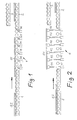
- the drawings show a flat glass conveyor line in side view, with a feed branch 1, a first discharge branch 2 in the plane of the feed branch 1, and a second Discharge branch 3, which is parallel to the first discharge branch 2 is arranged to this, the two discharge branches 2 and 3 are aligned with the feed branch 1 in the transport direction, and with one between the feed branch 1 and the discharge branches 2, 3 arranged transport switch 4. Also three consecutively transported on the conveyor line Glass panels G1, G2, G3 drawn to the mode of operation of the To make the transport switch clear. The glass panel G1 should be directed to the lower branch 2, the following Glass plate G2 is to be redirected to the upper discharge branch 3 and the following glass panel G3 should again get to the lower discharge branch 2.
- Figure 1 shows the conveyor line with the transport switch 4 in their one operating position, in which they the feed branch 1 with the lower discharge branch lying on the same level 2 connects.
- the distances are between the successive glass panels G1, G2, G3 clearly less than the length L of the transport switch 4.
- the conveying direction is marked by an arrow.
- the first one Glass panel G1 already has the transport switch 4 for the most part passes and runs on the lower discharge branch 2. Die the next following glass panel G2 is already partially on the transport switch 4; you follow the next glass plate G3 on the feed branch 2.
- Figure 2 shows the position of the transport switch 4 in the other Operating position in which the second glass sheet G2, while remaining in a horizontal position, to the level of the upper discharge branch 3 is raised and continue to run on it can.
- Figure 2 also shows the construction of the transport switch 4 clearly. It consists of a number of in the direction of transport successive short roller conveyor segments 41, 42, 43, 44, 45, 46, each in the drawings are symbolically represented by a conveyor roller, and the individually and independently of each other between the lower Position (Figure 1) and the upper position ( Figure 2) can be raised are lowerable.
- These liftable turnout segments 41 to 46 can, as shown in the drawings, alternately with fixed short roller conveyor sections 47 may be arranged or in immediate succession. They each include driven conveyor rollers, so that the transport movement one on the transport switch located glass plate, here the glass plate G2, too continuously during the lifting of the transport switch segments goes on.
- the lifting and lowering of the transport switch segments 41 to 46 takes place under computer control in synchronization with the transport of the Glass panels on the conveyor line and, if necessary, taking into account the size of the individual glass panels or their Length in the conveying direction.
- the lifting switch segments 41 to 46 are lifted simultaneously and synchronously as soon as the glass sheet in question G2 is largely or to a sufficient extent on the transport switch area to be able to be lifted.
- FIGS. 3A to 3C show highlights three phases of the return of the transfer switch in the lower position during the further movement of the glass panels on the conveyor line.
- 3B and 3C show like the next glass sheet G3 already in the transport switch area runs in while the outlet is still on the upper discharge branch 3 redirected glass sheet G2 from the transport switch area is underway.
Landscapes
- Engineering & Computer Science (AREA)
- Mechanical Engineering (AREA)
- Branching, Merging, And Special Transfer Between Conveyors (AREA)
- Relays Between Conveyors (AREA)
- Joining Of Glass To Other Materials (AREA)
Abstract
Description
Die Erfindung bezieht sich auf eine Transportweiche für eine Förderstrecke für Rollenförderer-geeignetes Plattenmaterial. Insbesondere findet die Erfindung als Transportweiche für eine Flachglas-Förderstrecke Anwendung. Die Erfindung kann aber auch bei Förderstrecken für andere Plattenmaterialien Anwendung finden, beispielsweise im Baubereich für Rigipsplatten, die in ähnlicher Weise wie Flachglas auf einer Produktionslinie als kontinuierliches Plattenband erzeugt und dann durch Schneiden in einzelne Plattenformate aufgeteilt werden.The invention relates to a transfer switch for a Conveyor line for plate material suitable for roller conveyors. In particular, the invention is used as a transport switch for a flat glass conveyor line application. The invention can but also for conveyor lines for other plate materials Find application, for example in the construction area for plasterboard, which is similar to flat glass on a production line produced as a continuous plate belt and then divided into individual plate formats by cutting become.
Bei der Flachglasproduktion läuft das Glas kontinuierlich in Form eines mehrere Meter breiten Bands aus dem Glasofen aus und gelangt auf eine Förderstrecke, die das Flachglasband mit definierter Fördergeschwindigkeit synchron zur Glasbanderzeugung am Ofenauslaß abfördert. Diese Förderstrecken umfassen von dem Bereich an, wo das Glasband ausreichend abgekühlt worden ist und entsprechende Festigkeit erlangt hat, Rollenförderer. Entlang der Förderstrecke erfolgt zunächst synchron mit der kontinuierlichen Förderbewegung des Glasbands das optische Prüfen des Glases auf Fehler wie Einschlüsse, Gasblasen usw., und deren Markierung, sowie das Querschneiden des Glasbands, üblicherweise unter Rechnersteuerung in unterschiedliche Formate, sowie auch das Längsritzen der durch Querschneiden hergestellten Glastafeln. Durch Beschleunigungsabschnitte in der Förderstrecke werden Abstände zwischen den aufeinanderfolgenden durch Querschneiden entstandenen Glastafeln erzeugt.In flat glass production, the glass runs in continuously Form a band several meters wide from the glass furnace and arrives on a conveyor line that the flat glass belt with defined conveying speed synchronous to the production of glass strips at the furnace outlet. These include conveyor lines from the area where the glass ribbon has cooled sufficiently roller conveyors. Along the conveyor line is initially synchronous with the continuous conveying movement of the glass ribbon that optical inspection of the glass for defects such as inclusions, gas bubbles etc., and their marking, as well as cross cutting of the glass ribbon, usually under computer control in different Formats, as well as the longitudinal scribing of through Cross cutting manufactured glass panels. Through acceleration sections In the conveyor line, distances between the successive ones created by cross cutting Glass panels produced.
Anschließend kann der Materialfluß der Glastafeln, der zum Zwecke der Verschnittoptimierung unter optimaler Aussparung von Glasfehlern in unterschiedliche Formate quergeschnitten und längs geritzt worden ist und daher als formatgrößengemischter Glastafelstrom auf der Förderstrecke befördert wird, mittels Transportweichen auf verschiedene Förderstreckenzweige verteilt werden, um dann beispielsweise ein formatgrößenreines Stapeln der Glastafeln zu ermöglichen. Solche Transportweichen schalten, da wegen des kontinuierlichen Glasplattenflusses die Transportrichtung erst einmal beibehalten werden muß, zwischen einer in der Ebene der Zuförderstrecke gelegenen Förderstreckenzweig und einem über diesem angeordneten parallelen Förderstreckenzweig um.Then the material flow of the glass sheets, which for Purpose of waste optimization with optimal recess of glass defects cut into different formats and has been scratched lengthways and therefore as a mixed format Glass sheet stream is transported on the conveyor line, by means of transport switches on different conveyor track branches distributed, for example, then a format-sized To allow stacking of the glass panels. Such transport switches switch because of the continuous flow of glass plates the direction of transport must be maintained for the time being must, between one located in the plane of the feed line Production line branch and one arranged above this parallel conveyor branch.
Bei bekannten Glasproduktionslinien (siehe z.B. US-A-3194417) sind solche Transportweichen als Förderstreckenabschnitte eines Rollenförderers ausgebildet, die zwischen einer horizontalen Betriebsstellung, in der sie die ankommenden Glastafeln auf den in derselben Ebene liegenden Förderstreckenzweig weiterleiten, und einer um das stromaufwärtige Ende in eine Schrägstellung geschwenkten rampenartigen Position umschaltbar, in welcher sie die ankommenden Glastafeln rampenartig auf den oberen Förderstreckenzweig umlenken.In known glass production lines (see e.g. US-A-3194417) such transport switches are designed as conveyor sections of a roller conveyor, between a horizontal operating position, in which they put the arriving glass panels on the same Forward level conveyor branch, and one pivoted into an inclined position around the upstream end ramp-like position switchable, in which it the arriving glass panels like a ramp on the upper conveyor branch redirect.
Diese bekannten Transportweichen in herkömmlichen Glasproduktionlinien sind aber nicht frei von Problemen. Zum einen haben die Glastafeln mit etwa 1 Meter pro Sekunde eine bemerkenswerte Geschwindigkeit, und die Förderrichtungsänderung aus der Horizontalen auf der rampenartig angestellten Transportweiche führt zu harten Schlägen an der Vorderkante einer ankommenden Glastafel, und beim Abkippen aus der rampenartig angestellten Transportweiche auf die oben liegende, wieder horizontal verlaufende weitere Förderstrecke treten erneut Beanspruchungen der Glastafel durch Aufschlagen auf die wieder horizontale Förderbahn auf. Dadurch können Glasbrüche auftreten, wobei diese Gefahr insbesondere dadurch gesteigert wird, daß die ankommenden und umgelenkten Glastafeln bereits längs geritzt sind, so daß es gerade dort ungewollt zum Bruch kommen kann. Ein zweites Problem besteht darin, daß die Transportweichen aufgrund der begrenzten möglichen Steilheit der rampenförmigen Stellung eine entsprechende Länge in Transportrichtung haben müssen und ein Umschalten zwischen den beiden Positionen erst möglich ist, nachdem eine ankommende Glastafel die Transportweiche vollständig passiert hat. Dies gilt insbesondere für das Aufschwenken in die rampenartige Stellung. Unter Einschluß der für das Umschalten benötigten Zeit bedeutet dies, daß der Abstand zwischen aufeinanderfolgenden Glastafeln auf der Förderstrecke größer als die Länge der Transportweiche sein muß.These well-known transport switches in conventional glass production lines but are not free of problems. On the one hand the glass panels have a remarkable rate of about 1 meter per second Speed, and the conveying direction change from the horizontal on the ramp-like transport switch leads to hard blows on the front edge of a arriving glass panel, and when tipping off the ramp-like employed transport switch to the one above, again horizontally running further conveyor track occur again Stresses the glass sheet by striking it again horizontal conveyor track. This can cause glass breaks occur, which increases this risk in particular is that the incoming and redirected glass panels already are scratched lengthways so that it breaks there unintentionally can come. A second problem is that the Transport switches due to the limited possible steepness the ramp-shaped position a corresponding length in Must have transport direction and switch between the two positions is only possible after an incoming Glass panel has completely passed the switch. This applies in particular to the swinging up into the ramp-like Position. Including those required for switching Time means that the distance between successive Glass panels on the conveyor line larger than that The length of the transport switch must be.
Der Erfindung liegt die Aufgabe zugrunde, eine verbesserte Transportweiche zu schaffen, die beide Probleme herkömmlicher Transportweichen vermeidet, nämlich schlagartige Beanspruchungen der Glastafeln ausschließt und damit die Gefahr der Beschädigung bzw. des Glasbruchs vermeidet und zum anderen kürzere Abstände der auf der Transportstrecke aufeinanderfolgenden Glastafeln ermöglicht, als das bei den herkömmlichen Transportweichen der Fall ist. Die Aufgabe gilt sinngemäß auch für eine Transportweiche für andere Plattenmaterialien als Flachglas, beispielsweise Rigipsplatten, die mechanisch empfindlich sind und bei deren Förderung gleichartige Probleme auftreten.The invention has for its object an improved To create transport switch, both problems more conventional Avoids transport switches, namely sudden stresses excludes the glass panels and thus the risk of damage or the glass breakage and on the other hand shorter ones Distances of the successive on the transport route Glass panels made possible than the conventional ones Transport switches is the case. The task applies accordingly also for a transport switch for other board materials as flat glass, for example plasterboard, the mechanically are sensitive and similar problems in promoting them occur.
Diese Aufgabe wird gemäß der Erfindung durch die im Patentenspruch angegebene Anordnung gelöst.This object is achieved according to the invention by the in the patent claim specified arrangement solved.
Ein Ausführungsbeispiel der Erfindung wird nachstehend unter Bezugnahme auf die anliegenden Zeichnungen beschrieben, in denen zeigt:
- Fig. 1.
- Eine Flachglas-Förderstrecke mit Transportweiche in Seitenansicht in der einen Betriebsstellung,
- Fig. 2
- die Anordnung nach
Figur 1 mit der Transportweiche in der anderen Betriebsstellung, - die Figuren 3A bis 3C
- die Anordnung in aufeinanderfolgenden
Phasen des Rückführens
der Transportweiche aus der Betriebsstellung
nach
Figur 2 in die Betriebsstellung nachFigur 1.
- Fig. 1.
- A flat glass conveyor line with transport switch in side view in one operating position,
- Fig. 2
- 1 with the transfer switch in the other operating position,
- Figures 3A to 3C
- the arrangement in successive phases of returning the transport switch from the operating position according to FIG. 2 to the operating position according to FIG. 1.
Die Zeichnungen sind sehr schematisch gehalten und sollen nur das Prinzip der Erfindung verdeutlichen.The drawings are very schematic and are only meant to be illustrate the principle of the invention.
Die Zeichnungen zeigen eine Flachglas-Förderstrecke in Seitenansicht,
mit einem Zuförderzweig 1, einem ersten Abförderzweig
2 in der Ebene des Zuförderzweigs 1, und einem zweiten
Abförderzweig 3, der über den ersten Abförderzweig 2 parallel
zu diesem angeordnet ist, wobei die beiden Abförderzweige 2
und 3 mit dem Zuförderzweig 1 in Transportrichtung fluchten,
und mit einer zwischen dem Zuförderzweig 1 und den Abförderzweigen
2, 3 angeordneten Transportweiche 4. Außerdem sind
drei aufeinanderfolgend auf der Förderstrecke transportierte
Glastafeln G1, G2, G3 eingezeichnet, um die Wirkungsweise der
Transportweiche deutlich werden zu lassen. Die Glastafel G1
soll auf den unteren Abföderzweig 2 geleitet werden, die folgende
Glastafel G2 soll auf den oberen Abförderzweig 3 umgeleitet
werden, und die dann folgende Glastafel G3 soll wiederum
auf den unteren Abförderzweig 2 gelangen.The drawings show a flat glass conveyor line in side view,
with a
Figur 1 zeigt die Förderstrecke mit der Transportweiche 4 in
ihrer einen Betriebsstellung, in welcher sie den Zuförderzweig
1 mit dem damit in gleicher Ebene liegenden unteren Abförderzweig
2 verbindet. Wie man sieht, sind die Abstände
zwischen den aufeinanderfolgenden Glastafeln G1, G2, G3 deutlich
kleiner als die Länge L der Transportweiche 4. Die Förderrichtung
ist durch einen Pfeil markiert. Die vorderste
Glastafel G1 hat die Transportweiche 4 schon zum größten Teil
passiert und läuft auf den unteren Abförderzweig 2. Die
nächstfolgende Glastafel G2 befindet sich schon teilweise auf
der Transportweiche 4; ihr folgt die nächstfolgende Glastafel
G3 auf dem Zuförderzweig 2.Figure 1 shows the conveyor line with the
Figur 2 zeigt die Stellung der Transportweiche 4 in der anderen
Betriebsstellung, in welcher die zweite Glastafel G2,
während sie in horizontaler Lage verbleibt, auf das Niveau
des oberen Abförderzweigs 3 angehoben ist und auf diesen weiterlaufen
kann.Figure 2 shows the position of the
Aus Figur 2 wird auch der konstruktive Aufbau der Transportweiche
4 deutlich. Er besteht aus einer Anzahl von in Transportrichtung
aufeinanderfolgender kurzer Rollenförderersegmente
41, 42, 43, 44, 45, 46, die in den Zeichnungen jeweils
durch eine Förderrolle symbolisch dargestellt sind, und die
jeweils einzeln und unabhängig voneinander zwischen der unteren
Position (Figur 1) und der oberen Position (Figur 2) anhebbar
bzw. absenkbar sind. Diese anhebbaren Transportweichensegmente
41 bis 46 können, wie in den Zeichnungen dargestellt,
jeweils abwechselnd mit feststehenden kurzen Rollenfördererabschnitten
47 angeordnet sein oder unmittelbar aufeinanderfolgen.
Sie umfassen jeweils angetriebene Förderrollen,
so daß die Transportbewegung einer auf der Transportweiche
befindlichen Glastafel, hier der Glastafel G2, auch
während des Anhebens der Transportweichensegmente kontinuierlich
weiter geht.Figure 2 also shows the construction of the
Das Anheben und Absenken der Transportweichensegmente 41 bis
46 erfolgt rechnergesteuert synchron mit dem Transport der
Glastafeln auf der Förderstrecke und gegebenenfalls unter Berücksichtigung
der Größe der einzelnen Glastafeln bzw. deren
Länge in Förderrichtung.The lifting and lowering of the
Das Anheben der Transportweichensegmente 41 bis 46 erfolgt
gleichzeitig und synchron, sobald die betreffende Glastafel
G2 sich weitgehend bzw. in ausreichendem Maße auf dem Transportweichenbereich
befindet, um angehoben werden zu können. The
Das Absenken der Transportweichensegmente wieder in die untere
Position erfolgt jedoch nicht mehr gleichzeitig, sondern
gestaffelt, also einzeln nacheinander und synchron mit der
Weiterbewegung der von den Transportweichensegmenten angehobenen
Glastafel G2. Sobald die betreffende Glastafel mit
ihrem rückwärtigem Endbereich das betreffende Transportweichensegment
verlassen hat, erfolgt dessen Absenkung in die
untere Position. Die Figuren 3A bis 3C zeigen schlaglichtartig
drei Phasen des Rückführvorgangs der Transportweiche in
die untere Position während der Weiterbewegung der Glastafeln
auf der Förderstrecke. Dabei zeigen die Figuren 3B und 3C,
wie die nächstfolgende Glastafel G3 schon in den Transportweichenbereich
einläuft, während noch der Auslauf der auf den
oberen Abführzweig 3 umgeleiteten Glastafel G2 aus dem Transportweichenbereich
im Gange ist.Lowering the transport switch segments back into the lower one
Position no longer occurs simultaneously, however
staggered, i.e. one after the other and in sync with the
Further movement of the lift switch segments raised
Glass panel G2. As soon as the relevant glass panel with
the relevant turnout segment at its rear end region
has left, it is lowered into the
lower position. FIGS. 3A to 3C show highlights
three phases of the return of the transfer switch in
the lower position during the further movement of the glass panels
on the conveyor line. 3B and 3C show
like the next glass sheet G3 already in the transport switch area
runs in while the outlet is still on the
Mit der erfindungsgemäß ausgebildeten Transportweiche könnte auch, was bei den herkömmlichen, in eine Rampenstellung umschaltbaren Transportweichen nicht möglich ist, eine Materialflußaufteilung auf 3 Abförderzweige realisiert werden, indem zwei Abförderzweige in zwei Etagen über dem mit dem Zuförderzweig ebenen gleichen Abförderzweig angeordnet werden, und auch ein unter dem mit dem Zuförderzweig ebenen gleichen Abförderzweig angeordneter Abförderzweig wäre denkbar.With the transport switch designed according to the invention also what the conventional switchable to a ramp position Transport switches are not possible, a material flow distribution can be realized on 3 discharge branches, by two discharge branches on two levels above the one with the feed branch same level discharge branch are arranged, and also one under the same one with the feeder branch A discharge branch arranged would be conceivable.
Claims (1)
- Transport points for conveyor lines for plate materials, for switching the flow of plate material between a supply branch (1) and at least two discharge branches (2, 3) which are arranged aligned with the supply branch (1) in the transport direction and of which the one discharge branch (2) is situated in the same plane as the supply branch (1) and the other discharge branch (3) lies at a level offset in height, in which the transport points (4) are formed by a multiplicity of short conveyor line segments (41 to 46) which are arranged successively in the transport direction and can be moved individually between the level of the first discharge branch (2) and the level of the second discharge branch (3), and in which these segments can be height-adjusted together and in synchrony for transferring a plate from the supply branch (1) to the height-offset discharge branch (3) and can be returned individually and successively to the level of the supply branch (1) in synchrony with the exit of the plate into the height-offset discharge branch (3).
Applications Claiming Priority (3)
| Application Number | Priority Date | Filing Date | Title |
|---|---|---|---|
| DE10053852 | 2000-10-30 | ||
| DE10053852A DE10053852A1 (en) | 2000-10-30 | 2000-10-30 | Transport switch for plate material conveyor line, especially flat glass conveyor line |
| PCT/DE2001/004057 WO2002036467A1 (en) | 2000-10-30 | 2001-10-30 | Transport switch for a plate material conveyor line, especially a flat glass conveyor line |
Publications (2)
| Publication Number | Publication Date |
|---|---|
| EP1337450A1 EP1337450A1 (en) | 2003-08-27 |
| EP1337450B1 true EP1337450B1 (en) | 2004-04-14 |
Family
ID=7661607
Family Applications (1)
| Application Number | Title | Priority Date | Filing Date |
|---|---|---|---|
| EP01992680A Expired - Lifetime EP1337450B1 (en) | 2000-10-30 | 2001-10-30 | Transport switch for a plate material conveyor line, especially a flat glass conveyor line |
Country Status (6)
| Country | Link |
|---|---|
| US (1) | US6669003B2 (en) |
| EP (1) | EP1337450B1 (en) |
| AT (1) | ATE264247T1 (en) |
| CA (1) | CA2395860A1 (en) |
| DE (2) | DE10053852A1 (en) |
| WO (1) | WO2002036467A1 (en) |
Families Citing this family (14)
| Publication number | Priority date | Publication date | Assignee | Title |
|---|---|---|---|---|
| US7296673B2 (en) * | 2005-06-10 | 2007-11-20 | Applied Materials, Inc. | Substrate conveyor system |
| US7284651B2 (en) * | 2005-06-20 | 2007-10-23 | Durr Systems, Inc. | Conveyor system and method of conveying elements |
| US7497317B2 (en) * | 2005-11-02 | 2009-03-03 | Chunghwa Picture Tubes, Ltd. | Apparatus for conveying and raising objects |
| DE102006039697B4 (en) * | 2006-08-21 | 2010-07-29 | SSI Schäfer Noell GmbH Lager- und Systemtechnik | Device and method for unloading trays loaded with pallet layers |
| DE102007058786B3 (en) * | 2007-12-06 | 2009-01-29 | Grenzebach Maschinenbau Gmbh | Device and method for discharging glass plates in a production line and computer program and machine-readable carrier therefor |
| US8826851B2 (en) * | 2008-07-17 | 2014-09-09 | Oberlikon Solar AG, Trubbach | Cover for a roller |
| CN102009840B (en) * | 2010-11-10 | 2012-08-01 | 友达光电股份有限公司 | Conveying device |
| AU2013287004A1 (en) * | 2012-07-05 | 2015-01-15 | Laitram, L.L.C. | Rotating-spiral diverter |
| DE102013102843B4 (en) * | 2013-03-20 | 2016-03-17 | Elopak Systems Ag | Method and device for removing packaging containers |
| ITUB20152553A1 (en) * | 2015-07-28 | 2017-01-28 | Biesse Spa | PROCESS OF PROCESSING GLASS SHEETS, STONE, MARBLE OR THE LIKE, OF LARGE DIMENSIONS IN A NUMERIC CONTROLLED WORK CENTER |
| US9745137B1 (en) * | 2016-06-03 | 2017-08-29 | Zme, Llc | Apparatus, system and method for material handling and/or processing |
| DE102018133052A1 (en) * | 2018-12-20 | 2020-06-25 | Deutsche Post Ag | Continuous conveyor for conveying objects and object conveyor hall with continuous conveyor |
| CN113320880A (en) * | 2021-06-08 | 2021-08-31 | 北京七星华创集成电路装备有限公司 | Conveying assembly for liquid crystal panel clamp and liquid crystal panel manufacturing equipment |
| DE102022128965A1 (en) | 2022-11-02 | 2024-05-02 | Amova Gmbh | Cross conveyors for roller tables |
Family Cites Families (19)
| Publication number | Priority date | Publication date | Assignee | Title |
|---|---|---|---|---|
| US2693135A (en) * | 1949-03-15 | 1954-11-02 | Stimson Lumber Company | Hot plate press loader |
| US2856055A (en) * | 1954-05-10 | 1958-10-14 | Petersen Oven Co | Tunnel oven unloader |
| US2921663A (en) * | 1956-05-16 | 1960-01-19 | Coe Mfg Co | Sheet handling apparatus |
| US3169630A (en) * | 1962-04-16 | 1965-02-16 | Western Electric Co | Conveyor mechanism |
| US3194417A (en) * | 1964-08-03 | 1965-07-13 | Libbey Owens Ford Glass Co | Method and apparatus for transferring sheets from a first conveyor to a second conveyor |
| DE2040879C3 (en) * | 1970-08-18 | 1974-01-17 | Alfred 2000 Hamburg Wriedt | Device for moving objects by means of several conveyor rollers connected to negative pressure |
| DE2041686C3 (en) * | 1970-08-21 | 1973-11-29 | Guenter 7421 Mehrstetten Stumpf | Ford magazine |
| US4047625A (en) * | 1974-05-21 | 1977-09-13 | Willson Barrat David Grant | Gravity roller conveyors |
| GB1463036A (en) * | 1975-06-03 | 1977-02-02 | Ni I Pt I Mash | Conveyors |
| US4016969A (en) * | 1975-07-22 | 1977-04-12 | Ppg Industries, Inc. | Flow dividing mechanism for a conveyor system |
| JPS6422758A (en) * | 1987-07-16 | 1989-01-25 | Meinan Machinery Works | Distributed transport device for board |
| JPH0266020A (en) * | 1988-08-31 | 1990-03-06 | Eidai Co Ltd | Method for conveyance of coated decorative sheet into coating surface dryer and decorative sheet conveyor |
| US5205394A (en) * | 1991-02-22 | 1993-04-27 | Natec, Reich, Summer Gmbh & Co. Kg. | Device for the perpendicular change in the direction of conveyance of a foodstuff, in particular cheese, sausage and similar product in slice form |
| US5284252A (en) * | 1991-11-13 | 1994-02-08 | United Parcel Service Of America, Inc. | Automatic rotary sorter |
| DE4339092C2 (en) * | 1993-11-16 | 1995-10-19 | Hubertus Dipl Ing Hein | Transport device for flat material |
| JPH08169536A (en) * | 1994-12-20 | 1996-07-02 | Honda Motor Co Ltd | Automatic carrying method and its device for work piece |
| IT1276144B1 (en) * | 1995-11-16 | 1997-10-27 | Cml Handling Technology S P A | APPARATUS AND METHOD FOR LOADING OBJECTS ON A SORTING MACHINE WITH TRANSPORT PLANS ON TWO LEVELS |
| IT1305875B1 (en) * | 1998-12-18 | 2001-05-21 | Lanfranco Anzani | GRAVITY HANDLING DEVICE, FOR AUTOMATED WAREHOUSES |
| DE10005752A1 (en) * | 2000-02-09 | 2001-08-23 | Schuler Pressen Gmbh & Co | Assembly for stacking large sheet plate components from a press station has direction change points to divert the pressed workpieces into two or more stacking belts in a start/stop feed to gripping transfer units or for manual removal |
-
2000
- 2000-10-30 DE DE10053852A patent/DE10053852A1/en not_active Withdrawn
-
2001
- 2001-10-30 DE DE50102017T patent/DE50102017D1/en not_active Expired - Fee Related
- 2001-10-30 EP EP01992680A patent/EP1337450B1/en not_active Expired - Lifetime
- 2001-10-30 CA CA002395860A patent/CA2395860A1/en not_active Abandoned
- 2001-10-30 AT AT01992680T patent/ATE264247T1/en not_active IP Right Cessation
- 2001-10-30 WO PCT/DE2001/004057 patent/WO2002036467A1/en active IP Right Grant
-
2002
- 2002-07-09 US US10/190,657 patent/US6669003B2/en not_active Expired - Lifetime
Also Published As
| Publication number | Publication date |
|---|---|
| DE50102017D1 (en) | 2004-05-19 |
| WO2002036467A1 (en) | 2002-05-10 |
| US20020175043A1 (en) | 2002-11-28 |
| EP1337450A1 (en) | 2003-08-27 |
| CA2395860A1 (en) | 2002-05-10 |
| DE10053852A1 (en) | 2002-05-16 |
| US6669003B2 (en) | 2003-12-30 |
| ATE264247T1 (en) | 2004-04-15 |
Similar Documents
| Publication | Publication Date | Title |
|---|---|---|
| EP0403901B2 (en) | Sorting device for cut flat elements | |
| EP1337450B1 (en) | Transport switch for a plate material conveyor line, especially a flat glass conveyor line | |
| DE2648269C2 (en) | Method and device for breaking flat glass panes into small pieces or shards | |
| DE69934375T2 (en) | Plant for producing and packaging roll-shaped objects | |
| DD141916A5 (en) | METHOD AND DEVICE FOR TRANSPORTING PLATES | |
| DE1556146A1 (en) | Method and device for the transport of table-shaped pieces | |
| DE2702724C2 (en) | Device for sorting and storing blanks in panel dividing systems | |
| DE2728016C3 (en) | Horizontal conveyor for glass sheets | |
| DE1235811B (en) | Device for nested, layer-wise stacking of profiled rolling stock | |
| AT405821B (en) | SORTING AND STACKING DEVICE | |
| EP0465916B1 (en) | Conveying device for stapled units | |
| DE4003024C2 (en) | ||
| DE3023008A1 (en) | Conveyor switch points installation - is fitted with two inclined roller tracks arranged in V=shape and with backward angled rollers for books transport | |
| AT384800B (en) | Distributing table for plate-like workpieces or workpiece assemblies | |
| DE3916686C2 (en) | Matrix distributors | |
| AT405508B (en) | Sorting and stacking apparatus for panel-cutting installations | |
| EP0867264B1 (en) | Apparatus for feeding insulating filler material during the production of sandwich boards | |
| DE3926966A1 (en) | Device for forming gaps in overlapping material flow - has stationary guide rollers and different speeds for outlet conveyor | |
| DE3734655A1 (en) | Installation for dividing plates and conveying and stacking the blanks | |
| EP1609747A1 (en) | Device for redirecting crates conveyed on a first conveyor | |
| EP0168573B1 (en) | Device for positioning burning saggers on a transporting surface | |
| DE3502279A1 (en) | Device for charging an operating apparatus, especially a heating furnace, with rod-shaped material and the like such as, in particular, rod-shaped semifinished product | |
| DE3431819A1 (en) | DISCHARGE RUNNING OF A FORGING BLOCK HEATING SYSTEM | |
| WO2019206858A1 (en) | Device and method for transporting containers, comprising a switch unit | |
| DE1481349A1 (en) | Process and system for the uniform and smooth division of a stream, which is conveyed on a track at high speed, of pieces located closely behind one another on several tracks |
Legal Events
| Date | Code | Title | Description |
|---|---|---|---|
| PUAI | Public reference made under article 153(3) epc to a published international application that has entered the european phase |
Free format text: ORIGINAL CODE: 0009012 |
|
| 17P | Request for examination filed |
Effective date: 20020802 |
|
| AK | Designated contracting states |
Designated state(s): AT BE CH CY DE DK ES FI FR GB GR IE IT LI LU MC NL PT SE TR |
|
| GRAP | Despatch of communication of intention to grant a patent |
Free format text: ORIGINAL CODE: EPIDOSNIGR1 |
|
| GRAS | Grant fee paid |
Free format text: ORIGINAL CODE: EPIDOSNIGR3 |
|
| GRAA | (expected) grant |
Free format text: ORIGINAL CODE: 0009210 |
|
| AK | Designated contracting states |
Kind code of ref document: B1 Designated state(s): AT BE CH CY DE DK ES FI FR GB GR IE IT LI LU MC NL PT SE TR |
|
| PG25 | Lapsed in a contracting state [announced via postgrant information from national office to epo] |
Ref country code: IT Free format text: LAPSE BECAUSE OF FAILURE TO SUBMIT A TRANSLATION OF THE DESCRIPTION OR TO PAY THE FEE WITHIN THE PRESCRIBED TIME-LIMIT;WARNING: LAPSES OF ITALIAN PATENTS WITH EFFECTIVE DATE BEFORE 2007 MAY HAVE OCCURRED AT ANY TIME BEFORE 2007. THE CORRECT EFFECTIVE DATE MAY BE DIFFERENT FROM THE ONE RECORDED. Effective date: 20040414 Ref country code: CY Free format text: LAPSE BECAUSE OF FAILURE TO SUBMIT A TRANSLATION OF THE DESCRIPTION OR TO PAY THE FEE WITHIN THE PRESCRIBED TIME-LIMIT Effective date: 20040414 Ref country code: FI Free format text: LAPSE BECAUSE OF FAILURE TO SUBMIT A TRANSLATION OF THE DESCRIPTION OR TO PAY THE FEE WITHIN THE PRESCRIBED TIME-LIMIT Effective date: 20040414 Ref country code: IE Free format text: LAPSE BECAUSE OF FAILURE TO SUBMIT A TRANSLATION OF THE DESCRIPTION OR TO PAY THE FEE WITHIN THE PRESCRIBED TIME-LIMIT Effective date: 20040414 Ref country code: NL Free format text: LAPSE BECAUSE OF FAILURE TO SUBMIT A TRANSLATION OF THE DESCRIPTION OR TO PAY THE FEE WITHIN THE PRESCRIBED TIME-LIMIT Effective date: 20040414 Ref country code: TR Free format text: LAPSE BECAUSE OF FAILURE TO SUBMIT A TRANSLATION OF THE DESCRIPTION OR TO PAY THE FEE WITHIN THE PRESCRIBED TIME-LIMIT Effective date: 20040414 |
|
| REG | Reference to a national code |
Ref country code: GB Ref legal event code: FG4D Free format text: NOT ENGLISH |
|
| REG | Reference to a national code |
Ref country code: CH Ref legal event code: EP |
|
| GBT | Gb: translation of ep patent filed (gb section 77(6)(a)/1977) |
Effective date: 20040414 |
|
| REF | Corresponds to: |
Ref document number: 50102017 Country of ref document: DE Date of ref document: 20040519 Kind code of ref document: P |
|
| REG | Reference to a national code |
Ref country code: IE Ref legal event code: FG4D Free format text: GERMAN |
|
| PG25 | Lapsed in a contracting state [announced via postgrant information from national office to epo] |
Ref country code: DK Free format text: LAPSE BECAUSE OF FAILURE TO SUBMIT A TRANSLATION OF THE DESCRIPTION OR TO PAY THE FEE WITHIN THE PRESCRIBED TIME-LIMIT Effective date: 20040714 Ref country code: SE Free format text: LAPSE BECAUSE OF FAILURE TO SUBMIT A TRANSLATION OF THE DESCRIPTION OR TO PAY THE FEE WITHIN THE PRESCRIBED TIME-LIMIT Effective date: 20040714 Ref country code: GR Free format text: LAPSE BECAUSE OF FAILURE TO SUBMIT A TRANSLATION OF THE DESCRIPTION OR TO PAY THE FEE WITHIN THE PRESCRIBED TIME-LIMIT Effective date: 20040714 |
|
| PG25 | Lapsed in a contracting state [announced via postgrant information from national office to epo] |
Ref country code: ES Free format text: LAPSE BECAUSE OF FAILURE TO SUBMIT A TRANSLATION OF THE DESCRIPTION OR TO PAY THE FEE WITHIN THE PRESCRIBED TIME-LIMIT Effective date: 20040725 |
|
| NLV1 | Nl: lapsed or annulled due to failure to fulfill the requirements of art. 29p and 29m of the patents act | ||
| PG25 | Lapsed in a contracting state [announced via postgrant information from national office to epo] |
Ref country code: LU Free format text: LAPSE BECAUSE OF NON-PAYMENT OF DUE FEES Effective date: 20041030 Ref country code: AT Free format text: LAPSE BECAUSE OF NON-PAYMENT OF DUE FEES Effective date: 20041030 |
|
| PG25 | Lapsed in a contracting state [announced via postgrant information from national office to epo] |
Ref country code: MC Free format text: LAPSE BECAUSE OF NON-PAYMENT OF DUE FEES Effective date: 20041031 Ref country code: BE Free format text: LAPSE BECAUSE OF NON-PAYMENT OF DUE FEES Effective date: 20041031 |
|
| ET | Fr: translation filed | ||
| REG | Reference to a national code |
Ref country code: IE Ref legal event code: FD4D |
|
| PLBE | No opposition filed within time limit |
Free format text: ORIGINAL CODE: 0009261 |
|
| STAA | Information on the status of an ep patent application or granted ep patent |
Free format text: STATUS: NO OPPOSITION FILED WITHIN TIME LIMIT |
|
| 26N | No opposition filed |
Effective date: 20050117 |
|
| BERE | Be: lapsed |
Owner name: *GRENZEBACH MASCHINENBAU G.M.B.H. Effective date: 20041031 |
|
| PG25 | Lapsed in a contracting state [announced via postgrant information from national office to epo] |
Ref country code: DE Free format text: LAPSE BECAUSE OF NON-PAYMENT OF DUE FEES Effective date: 20050503 |
|
| PG25 | Lapsed in a contracting state [announced via postgrant information from national office to epo] |
Ref country code: FR Free format text: LAPSE BECAUSE OF NON-PAYMENT OF DUE FEES Effective date: 20050630 |
|
| REG | Reference to a national code |
Ref country code: FR Ref legal event code: ST |
|
| PG25 | Lapsed in a contracting state [announced via postgrant information from national office to epo] |
Ref country code: GB Free format text: LAPSE BECAUSE OF NON-PAYMENT OF DUE FEES Effective date: 20051030 |
|
| PG25 | Lapsed in a contracting state [announced via postgrant information from national office to epo] |
Ref country code: CH Free format text: LAPSE BECAUSE OF NON-PAYMENT OF DUE FEES Effective date: 20051031 Ref country code: LI Free format text: LAPSE BECAUSE OF NON-PAYMENT OF DUE FEES Effective date: 20051031 |
|
| REG | Reference to a national code |
Ref country code: CH Ref legal event code: PL |
|
| GBPC | Gb: european patent ceased through non-payment of renewal fee |
Effective date: 20051030 |
|
| BERE | Be: lapsed |
Owner name: *GRENZEBACH MASCHINENBAU G.M.B.H. Effective date: 20041031 |
|
| PG25 | Lapsed in a contracting state [announced via postgrant information from national office to epo] |
Ref country code: PT Free format text: LAPSE BECAUSE OF NON-PAYMENT OF DUE FEES Effective date: 20040914 |