Technical Field
The present invention relates to polymer electrolyte
fuel cells, and more particularly relates to an improvement of
the porous electrodes in the polymer electrolyte fuel cells.
Background Art
The basic principle of the polymer electrolyte fuel
cell includes exposing one side of a hydrogen ion conductive
polymer electrolyte membrane to a fuel gas such as hydrogen
and exposing the other side to oxygen to synthesize water by
chemical reaction through the electrolyte membrane, and
extracting the resulting reaction energy electrically. The
structure of this type of fuel cell is shown in FIG. 23.
A hydrogen ion conductive polymer electrolyte
membrane 1 and a pair of porous electrodes 2 including a
catalyst, which sandwich this electrolyte membrane 1, are
joined integrally by heat press or other method. The
resulting unit is called an electrolyte membrane-electrode
assembly (MEA), and can be handled independently. Disposed
outside of the electrodes 2 are a pair of conductive separator
plates 3 having gas flow paths 4 for supplying a fuel gas or
an oxidant gas to the respective electrodes. Placed between
each conductive separator plate and the peripheral portion of
the electrolyte membrane 1, which is present outside of the
electrodes 2, is a gasket 5 for preventing the gases from
leaking out. The reaction gases introduced from the gas flow
paths 4 of the separator plates 3 electrochemically react at
the porous electrodes 2 through the electrolyte membrane 1,
and the resulting electric power is collected outside through
the separator plates 3.
The requirements for the porous electrodes are good
conductivity, gas permeability, water permeability and
corrosion resistance. Hence, there has been used a technique
by which a carbon fiber (fiber which was baked at a
temperature of around 1000° C after a stabilization process and
has a graphitization degree of around 50%, this fiber being
hereinafter referred to as "carbon fiber") is made into paper
or woven into fabric so as to produce a sheet that
structurally has gas permeability (hereinafter referred to as
"carbonized paper" or "carbonized woven fabric"), and then the
sheet is treated with heat at 2000°C or higher temperature to
make graphite paper or graphite woven fabric having a
graphitization degree of not less than 80% so as to utilize
good electric conductivity, corrosion resistance and water
repellency of graphite carbon.
In principle, the polymer electrolyte fuel cell
needs to supply water participating in ionic conduction to the
anode, while water is produced in the cathode. Thus,
basically, the anode-side porous electrode needs to promptly
permeate the supplied water to the polymer electrolyte
membrane, and the cathode-side porous electrode needs to
promptly eliminate the generated water from the polymer
electrolyte membrane. It is therefore desirable that the
porous electrodes have water repellency. However, if there
are expectations for a reduction in water to be supplied and a
cooling effect provided by temporally storage of
supplied/generated water and latent heat of vaporization with
an abrupt increase/decrease in load, then appropriate water
retention property may be required.
In order to satisfy such controversial requirements,
there has been a proposal to use a water-repellent porous
electrode and a hydrophilic porous electrode to constitute a
porous electrode so as to partly impart hydrophilicity while
keeping water repellency as a whole. However, if the entire
surface is covered with the hydrophilic porous electrode,
there will be a problem that a phenomenon (flooding) in which
the hydrophilic porous electrode is clogged with water and
interferes with gas permeation is likely to occur.
Disclosure of Invention
The present invention provides a gas diffusion layer,
which is a porous electrode made of a conductive carbon fiber
sheet and comprises a gas flow path having a bottom face
facing the electrode membrane, or a gas flow path having a
bottom face facing the electrolyte membrane and a top face
facing the opposite side. Moreover, there is a difference in
the carbon fiber structure between the part forming the bottom
of the gas flow path and the part forming the side wall of the
gas flow path and/or the part forming the top face of the gas
flow path.
A polymer electrolyte fuel cell of the present
invention is a polymer electrolyte fuel cell comprising: an
electrolyte membrane-electrode assembly composed of a hydrogen
ion conductive polymer electrolyte membrane and a pair of
electrodes sandwiching the hydrogen ion conductive polymer
electrolyte membrane; and a pair of conductive separator
plates sandwiching the electrolyte membrane-electrode assembly,
and characterized in that each of the electrodes has a
catalyst layer in contact with the electrolyte membrane, and a
gas diffusion layer made of a conductive carbon fiber sheet in
contact with the catalyst layer, the gas diffusion layer
comprises a gas flow path having a bottom face facing the
electrolyte membrane, and the properties of a carbon fiber
that forms the bottom face of the gas flow path are different
from the properties of a carbon fiber that forms a side wall
of the gas flow path.
It is preferable that the hydrophilicity of the
carbon fiber forming the bottom of the gas flow path is lower
than that of the carbon fiber forming the side wall of the gas
flow path.
The present invention provides a polymer electrolyte
fuel cell comprising: an electrolyte membrane-electrode
assembly composed of a hydrogen ion conductive polymer
electrolyte membrane and a pair of electrodes sandwiching the
hydrogen ion conductive polymer electrolyte membrane; and a
pair of conductive separator plates sandwiching the
electrolyte membrane-electrode assembly, the polymer
electrolyte fuel cell being characterized in that each of the
electrodes has a catalyst layer in contact with the
electrolyte membrane; and a gas diffusion layer made of a
conductive carbon fiber sheet in contact with the catalyst
layer; the gas diffusion layer comprises a gas flow path
having a bottom face facing the electrolyte membrane and a top
face facing the opposite side, and the properties of a carbon
fiber that forms the bottom face of the gas flow path are
different from the properties of at least one of a carbon
fiber that forms the' top face of the gas flow path and a
carbon fiber that forms a side wall of the gas flow path.
Here, it is preferable that the hydrophilicity of
the carbon fiber forming the bottom face of the gas flow path
is lower than that of at least one of the carbon fiber forming
the top face of the gas flow path and the carbon fiber forming
the side wall of the gas flow path.
The difference in the graphitization degree,
graphite orientation degree, or the fiber microstructure is
derived from a difference between mutually different carbon
fiber materials selected from the group consisting of PAN-based,
pitch-based, cellulose-based, and phenol-based carbon
fiber materials.
The porous electrode can be made of a complex of a
flat carbon fiber sheet and a carbon fiber sheet having
grooves that form a gas flow path on one side.
It is preferable that the carbon fiber sheet having
the grooves and the flat carbon fiber sheet have different
properties from each other in at least one of their fiber
density, pore density, graphitization degree, graphite
orientation degree, fiber microstructure, and hydrophilic
group density.
Brief Description of Drawings
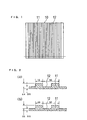
FIG. 1 is a plan view of a woven fabric made from
carbon fiber raw yarn that is a material for a porous
electrode in an example of the present invention.
FIG. 2 is a cross sectional view of the woven fabric.
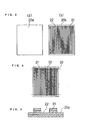
FIG. 3 is a plan view of two carbon fiber sheets to
be a material for a porous electrode in another example of the
present invention.
FIG. 4 is a plan view showing a state where the two
sheets are stacked.
FIG. 5 is a cross sectional view of the sheets.
FIG. 6 is a cross sectional view of a sheet produced
by weaving another carbon fiber into a fabric that will be a
material for a porous electrode in still another example of
the present invention.
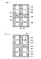
FIG. 7 is a cross sectional view showing a
structural example of an MEA.
FIG. 8 is a cross sectional view showing another
structural example of an MEA.
FIG. 9 is a cross sectional view showing still
another structural example of an MEA.
FIG. 10 is a cross sectional view showing the
process of locally imparting hydrophilicity to an electrode in
yet another example of the present invention.
FIG. 11 is a cross sectional view showing the
process of manufacturing a porous electrode in another example
of the present invention.
FIG. 12 is a cross sectional view of a porous
electrode obtained by the manufacturing process.
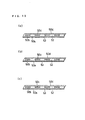
FIG. 13 is a cross sectional view showing examples
of the combination of sheets constituting a similar electrode.
FIG. 14 is a cross sectional view showing the
process of locally imparting hydrophilicity to an electrode in
still another example of the present invention.
FIG. 15 is a view showing the process of producing a
single electrode sheet from four layers of carbon fiber sheets.
FIG. 16 is a front view of the anode side of an MEA
in another example.
FIG. 17 is a top view of the MEA.
FIG. 18 is a front view of a cathode-side separator
plate.
FIG. 19 is a rear view of the cathode-side separator
plate.
FIG. 20 is a cross sectional view cut along the A-A'
line in FIG. 18.
FIG. 21 is a front view of an anode-side separator
plate.
FIG. 22 is a cross sectional view of essential parts
of a fuel cell of an example of the present invention.
FIG. 23 is a cross sectional view of essential parts
of a conventional fuel cell.
FIG. 24 is a view showing the relationship between
the anode bubbler temperature and the cell voltage at a
current density of 200 mA/cm2 in a fuel cell of an example of
the present invention and a fuel cell of a comparative example.
FIG. 25 is a view showing cell voltage behavior
corresponding to increase/decrease of fuel gas in the fuel
cells of the example of the present invention and the
comparative example.
FIG. 26 is a view showing the relationship between
the output current density and the amount of cooling water
necessary for keeping the cell temperature at 75°C in the fuel
cells of the example of the present invention and the
comparative example.
FIG. 27 is a plan view showing the state where
layers are exposed out of an electrode sheet composed of a
plurality of sheets.
FIG. 28 is a plan view showing how the water
repellency of the respective layers of the electrode sheet is
evaluated.
FIG. 29 is a view showing the X-ray diffraction
patterns and the water repellency index of the respective
layers of the electrode sheet.
Best Mode for Carrying Out the Invention
A gas diffusion layer for use in a polymer
electrolyte fuel cell of the present invention comprises a gas
flow path having a bottom face facing the electrolyte membrane
as described above, and the properties of a carbon fiber that
forms the bottom face of the gas flow path are different from
the properties of a carbon fiber that forms the side wall of
the gas flow path.
In another aspect, the gas diffusion layer of the
present invention comprises a gas flow path having a bottom
face facing the electrolyte membrane and a top face facing the
opposite side, and the properties of a carbon fiber that forms
the bottom face of the gas flow path are different from the
properties of at least one of a carbon fiber that forms the
top face of the gas flow path and a carbon fiber that forms
the side wall of the gas flow path.
Typical examples of conductive carbon fibers include
PAN-based, pitch-based, rayon-based (cellulose-based), and
phenol-based (kynol-based) graphite fibers, and the
graphitization degree that they can reach differs depending on
the properties of their starting materials. For example, in
the case of PAN-based and mesophase pitch-based (also called
liquid crystal pitch or anisotropic pitch) graphite fibers,
long fibers having a high degree of orientation are obtained
in the spinning stage, and the starting materials have simple
structure and can readily form a benzene ring. Therefore, if
such a fiber is carbonized and graphitized, a carbon fiber
with a high degree of crystal orientation and a high degree of
graphitization is obtained. On the other hand, in the case of
rayon-based and phenol-based graphite fibers, the degree of
crystal orientation and the degree of graphitization are both
low because of the difficulty in forming a benzene ring due to
the complexity of the starting materials and a low degree of
crystal orientation originated in the materials.
Even when graphite fibers are of the same type, it
is possible to obtain electrodes having differences in the
degree of orientation and the degree of graphitization by
changing the manufacturing conditions, such as temperature and
time. For example, in the case of pitch-based graphite fiber,
decant oil (the bottom oil in a petroleum refining
distillation column) is treated at a temperature of around
400°C to cause part of the benzene ring to have an anisotropic
property by condensation polymerization. Then, a mixture with
an isotropic part (mesophase pitch or liquid crystal pitch) is
oriented by spinning. Next, the mixture is stabilized,
carbonized and graphitized to obtain a graphite fiber. At
this time, by increasing or decreasing the treatment
temperature or the treatment time in the stage of
manufacturing the mesophase pitch, the ratio of the
anisotropic part and the isotropic part and the degree of
polymerization of the anisotropic part can be controlled.
Moreover, by increasing/decreasing the spinning temperature,
it is possible to obtain yarn with different degree of
orientation. Adoption of such preparation means is reflected
in the degree of crystal orientation and the degree of
graphitization of the finally obtained graphite fiber.
For example, a PAN-based graphite fiber is produced
mainly by the following processes, and, if any one of the
processes is incomplete, it is impossible to obtain a fiber
with a high degree of graphitization.
Therefore, for example, by producing a plurality of
carbon fibers having differences in their orientation
characteristic and graphite structure by decreasing the
treatment temperature in the carbonization process and
controlling the treatment time, and then bonding a plurality
of carbon fiber sheets, which were produced by making the
carbon fibers into paper or weaving the carbon fibers into a
fabric, together with a binder and graphitizing them under the
same condition, it is possible to readily produce a multi-layer
carbon sheet that has differences in the degree of
crystal orientation and graphitization between the respective
layers and thus has a water repellency gradient.
By chemically modifying the thus obtained carbon
sheets having differences in their degree of orientation and
graphitization by a suitable method, it is possible to adjust
the amount of water repellency gradient and order. In other
words, in a sheet having a high degree of crystal orientation
and graphitization, since the graphite crystal is chemically
inactive and there is no space for a modification group to
enter therein due to its high degree of orientation, it is
difficult to chemically modify such a sheet. On the contrary,
it is easy to chemically modify a sheet having a low degree of
orientation and graphitization. Hence, if the carbon sheets
are treated to have hydrophilicity by using a technique such
as oxidation with nitric acid, electrolytic oxidation (anodic
oxidation), and steam oxidation, for example, the amount of
gradient is increased according to the original water
repellency gradient order. On the other hand, after the
treatment to impart hydrophilicity, when a treatment to impart
water repellency is applied using a fluorocarbon-based water
repellent, for example, since the hydrophilic group is
modified with fluorocarbon, the carbon sheets have water
repellency in the order reverse to the original water
repellency gradient order, and the water repellency exceeds
the original water repellency. It is thus possible to produce
sheets having hydrophilic/water repellent functions of desired
order and strength by combining the process of manufacturing
the carbon sheets with the chemical modification process.
By taking the above into accounts, it is possible to
select materials for forming the respective parts of an
electrode made of carbon sheets with a gas flow path.
Moreover, a sheet that forms the bottom face of the gas flow
path and/or a sheet that forms the top face of the gas flow
path can also be composed of a plurality of sheets having
differences in their degree of crystal orientation and
graphitization.
Referring to the drawings, the following description
will explain some embodiments.
In a porous electrode having a gas flow path, a part
that needs to have gas permeability is the above-mentioned
part forming the bottom of the gas flow path, while a part
that needs not to have gas permeability is the above-mentioned
part forming the side wall of the gas flow path and the part
forming the top face of the gas flow path. Therefore, if the
part corresponding to the bottom of the gas flow path is made
from water repellent carbon fiber and the side-wall part of
the gas flow path and/or the top face part of the gas flow
path are made from hydrophilic carbon fiber, it is possible to
impart water repellency without sacrificing the gas
permeability.
The carbon fiber raw yarn in the spinning stage
before being stabilized by oxygen crosslinking has flexibility
and can be knitted into any shape. Hence, as shown in FIG. 1
and FIG. 2, a fiber fabric 10 having grooves 12 formed by
providing a number of protruding ribs 11 in parallel is
prepared, and it is stabilized, carbonized and graphitized.
In this manner, it is possible to readily obtain a porous
electrode having a gas flow path in the portion of the grooves
12. Moreover, since short fiber of carbon fiber can be made
into a mat and felt of any shape, it is possible to obtain a
porous electrode having a gas flow path in the same manner.
FIG. 6 shows an example in which a side-wall part 24
that forms a groove 25 is produced integrally by weaving
another carbon fiber yarn in a raw woven fabric.
The example illustrated above is a method suitable
for pitch-based and rayon-based carbon fibers which do not
produce much heat during stabilization. This method is not
suitable for PAN-based carbon fibers which produce a large
amount of heat during stabilization and are hard to stabilize
unless being a single yarn.
Next, a method applicable to PAN-based carbon fibers
is shown.
First, as shown in FIG. 3, a carbonized sheet 20a
produced by cutting long fiber to a suitable length and making
the fiber into paper is bonded to a sheet 20b having slits 22
formed by stamping the same carbonized sheet in a flow path
form with a binder (FIG. 4). Then, the binder and the
carbonized sheets 20a, 20b are graphitized together, and cut
along the broken lines shown in FIG. 4. Consequently, as
shown in FIG. 5, a carbon fiber sheet having grooves formed by
the slits 22 is obtained. FIG. 5 illustrates an example in
which two carbonized sheets 20a and two carbonized sheets 20b
are used. The side-wall part is made of the section 21 of the
sheets 20b.
By forming the gas flow path in this manner, even a
PAN-based carbon fiber which has poor flexibility and has, for
example, gone through the carbonization process and partially
developed graphite crystal can be formed into a shape similar
to that shown in FIG. 1. In other words, even when any kind
of carbon fiber is used, it is possible to form a gas flow
path according to a suitable processing method.
FIG. 7 shows an example of electrolyte membrane-electrode
assembly (MEA) comprising porous electrodes made of
carbon sheets obtained as described above. 32 represents a
hydrogen ion conductive polymer electrolyte membrane. A pair
of water repellent porous electrodes 31 formed by a common
method are placed to sandwich this electrolyte membrane 32. A
porous electrode 30 placed outside of the electrode 31 is a
hydrophilic porous electrode obtained by treating an electrode
having grooves 34 formed by a method as described above to
impart hydrophilicity using a technique such as oxidation with
nitric acid, electrolytic oxidation (anodic oxidation), and
steam oxidation, for example. Thus, in an electrode composed
of the water repellent porous electrode 31 and the hydrophilic
porous electrode 30, the bottom part that is the electrolyte
membrane side of the gas flow path 34 has water repellency,
while the side-wall part and top face part of the gas flow
path 34 have hydrophilicity. In short, with this structure,
it is possible to realize a porous electrode imparted with
hydrophilicity, without sacrificing the gas permeability. 33
represents a conductive separator plate.
For the raw fiber fabric 23 in FIG. 6 and the sheet
20a of woven fabric or paper which is not stamped in FIG. 3, a
carbon fiber having a high degree of crystal orientation and a
small surface area, for example, PAN-based or mesophase pitch-based
carbon fiber is used. On the other hand, for the carbon
fiber yarn woven in the raw fiber fabric 23 in FIG. 6 and the
sheet 20b of woven fabric or paper which is stamped in FIG. 3,
a carbon fiber having a low degree of crystal orientation
(glass form) and a large surface area, for example, phenol-based
activated carbon fiber is used. Then, by slightly
applying hydrophilic treatment after forming the carbon fibers
into the structure shown in FIG. 6 and FIG. 5, the carbon
fiber having a low degree of crystal orientation is given
priority in hydrophilic treatment and the carbon fiber having
a high degree of orientation has almost no hydrophilic
modification, thereby making it possible to manufacture a
single electrode having a water repellent part and a
hydrophilic part.
Examples of the MEA comprising porous electrodes
thus obtained are shown in FIG. 8 and FIG. 9.
FIG. 8 shows an example using an electrode made of a
carbon fiber sheet having the structure as shown in FIG. 6.
Specifically, this example uses an electrode in which a side-wall
part 36 of the gas flow path 34 was formed by weaving a
carbon fiber having a low degree of crystal orientation and a
large surface area in a sheet 35 made from a carbon fiber
having a high degree of crystal orientation and a small
surface area. The MEA is formed by sandwiching the
electrolyte membrane 32 between the sheets 35 of two pieces of
this electrode.
FIG. 9 shows an example using a carbon fiber sheet
having the structure as shown in FIG. 5. Specifically, this
example uses an electrode in which the side-wall part of the
gas flow path 34 is formed by joining three sheets 38 made
from a carbon fiber having a low degree of crystal orientation
and a large surface area to a sheet 37 made from a carbon
fiber having a high degree of crystal orientation and a small
surface area.
Even when the same carbon fibers are used, the water
repellent part and the hydrophilic part can be formed by
increasing/decreasing the fiber density. The reason for this
is that a capillary phenomenon can be utilized with an
increase in the density. Since the water repellent part has a
low density, the gas permeability is not sacrificed, and the
high-density hydrophilic part wet with water can sufficiently
function as a gas bulkhead between the flow paths.
With the use of the porous characteristic of the
electrode, it is possible to form the hydrophilic part by
filling the side-wall part of the gas flow path with a
hydrophilic agent, for example, silica gel. FIG. 10 shows the
process of manufacturing such an electrode.
First, a sheet 41 made from a carbon fiber is joined
to three sheets made from the same carbon fiber to produce a
side-wall part 42 that forms a gas flow path 43 (FIG. 10(a)).
Subsequently, a screen 45 is set on the side-wall part 42 (FIG.
10(b)), an ink containing a silica gel powder 47 is printed
(FIG. 10(c), and then the ink is pushed into the side-wall
part 42 by a pressure plate 46 (FIG. 10(d)). Consequently, an
electrode having the side-wall part 42 composed of a portion
42a made from the original carbon fiber and a portion 42b
filled with silica gel is formed (FIG. 10(e)).
By suitably combining the above-mentioned techniques,
it is possible to impart a desired hydrophilicity to the
hydrophilic part while ensuring sufficient gas permeability in
the water repellent part.
Next, the following description will explain another
method for manufacturing an electrode having a gas flow path
comprising the electrode membrane side as its bottom face and
the opposite side as its top face.
First, as shown in FIG. 11, carbonized sheets 50a,
50d produced by cutting long fiber to a suitable length and
making the fiber into paper and sheets 50b, 50c having slits
52 formed by stamping the same carbonized sheets in a flow
path form are stacked in the order of the sheets 50a, 50b, 50c
and 50d, and bonded together with a binder. Then, the binder
and the carbonized sheets are graphitized together, and cut
along the broken lines shown in FIG. 11(b). Consequently, as
shown in FIG. 12, an electrode comprising the sheet 50a as its
bottom face, the sheet 50d as its top face, and a gas flow
path formed by the slits 52 is obtained. Here, an example in
which the electrode is composed of four sheets of the same
material is illustrated, but it is needless to say that the
number of the sheets and the material can be changed according
to need.
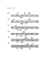
FIG. 13 shows examples of the combination of sheets
constituting an electrode produced in the above-described
manner. FIG. 13(a) shows an example in which PAN-based or
pitch-based water repellent carbon sheets are used for the
sheet 50a forming the bottom face of the gas flow path 52 and
for the sheets 50b, 50c forming the side-wall part of the gas
flow path, and a cellulose-based or phenol-based hydrophilic
carbon sheet is used for the sheet 50d forming the top face of
the gas flow path. In FIG. 13(b), a water repellent carbon
sheet is used for the sheet 50a that forms the bottom face of
the gas flow path 52, and hydrophilic carbon sheets are used
for the sheets 50b, 50c that form the side-wall part of the
gas flow path and for the sheet 50d that forms the top face of
the gas flow path. In FIG. 13(c), water repellent carbon
sheets are used for the sheet 50a that forms the bottom face
of the gas flow path 52 and for the sheet 50d that forms the
top face of the gas flow path, and hydrophilic carbon sheets
are used for the sheets 50b, 50c that form the side-wall part
of the gas flow path. In any of the examples, a water
repellent layer 53 is formed on the electrolyte membrane side
of the sheet 50a forming the bottom face of the gas flow path.
FIG. 14 shows an example of applying hydrophilic
treatment to a specific part of an electrode sheet produced by
a method as illustrated in FIG. 11, and of applying a water
repelling treatment to other specific portion.
A mask 65 is positioned on a sheet 60d of an
electrode sheet composed of a sheet 60a that forms the bottom
face of a gas flow path 62, sheet 60d that forms the top face,
and sheets 60b, 60c that form the side walls (FIG. 14(b)).
Subsequently, a hydrophilic material 64 is printed on the
surface on which the mask 65 is set (FIG. 14(c)), and the
sheet 60d is impregnated with this hydrophilic material 64
(FIG. 14(d)). Next, the entire sheet is reversed, and a water
repellent 63 is printed on the sheet 60a (FIG. 14(e)) and
treated with heat. Consequently, an electrode having the gas
flow path 62 comprising a top face made of the hydrophilic
sheet 60d and a bottom face made of the sheet 60a including
the water repellent layer 63 is obtained (FIG. 14(f)). The
hydrophilic agent used here is silica gel, for example, while
the water repellent is polytetrafluoroethylene, and the
temperature of the heat treatment is around 340°C. Suitable
hydrophilicity and water repellency are imparted by this heat
treatment.
Next, the following description will explain a
method for producing an electrode by binding two or three of
the carbon fiber sheet that forms the bottom face of the gas
flow path, the carbon sheets that form the side wall of the
gas flow path, and the carbon fiber sheet that forms the top
face of the gas flow path together with a graphitized material,
or producing an electrode made of a multi-layer sheet by
binding the sheets of the respective parts with a graphitized
material.
The device of FIG. 15 is explained. A first-layer
raw carbonized paper 72a, a second-layer raw carbonized paper
72b, a third-layer raw carbonized paper 72c, and a fourth-layer
raw carbonized paper 72d are fed from rolls 71a, 71b,
71c, and 71d, respectively. A binder is applied to the
carbonized paper 72b, 72c and 72d by coating rollers 73b, 73c
and 73d, respectively, and the carbonized paper 72b, 72c and
72d pass through rolls 74b, 74c and 74d and are then joined
onto the carbonized paper 72a by rolls 74a and 75b. Next, a
carbonized paper 76 obtained by joining the four layers
together is graphitized in a kiln 77, passes through rolls 78a
and 78b, and is then cut to an individual electrode size with
a cutter 79. Consequently, a single conductive carbon fiber
sheet 80 composed of four layers is obtained.
Next, the following description will explain the
structure of a fuel cell using the above-described gas
diffusion layers or porous electrodes of the present invention.
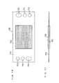
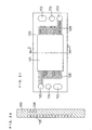
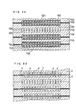
An MEA is shown in FIG. 16 and FIG. 17, a cathode-side
separator plate is shown in FIGS. 18 through 20, an
anode-side separator plate is shown in FIG. 21, and a fuel
cell is shown in FIG. 22.
An MEA 100 is composed of a polymer electrolyte
membrane 101, an anode 102 and a cathode 103 joined to both
sides of the polymer electrolyte membrane 101, and a gasket
110 covering the peripheral portion of the electrolyte
membrane. In the gasket 110, a pair of manifold apertures 112
for fuel gas, a pair of manifold apertures 113 for oxidant gas,
and a pair of manifold apertures 113 for cooling water are
formed. These manifold apertures are connected to manifold
apertures of the separator plate to be described later. In
this example, as shown in FIG. 22, the anode 102 and the
cathode 103 are formed by the combination of a water repellent
sheet 104 placed on the electrolyte membrane side and a
hydrophilic electrode sheet 105 having a gas flow path 106
made of grooves which are open on the sheet 104 side.
An anode-side separator plate 120 includes a pair of
manifold apertures 122 for fuel gas, a pair of manifold
apertures 123 for oxidant gas, and a pair of manifold
apertures 124 for cooling water. Furthermore, the anode-side
separator plate 120 has a recessed portion 121 on the side
facing the anode of the MEA, for accommodating the anode 102
in the center, and grooves 125 on both sides of this recessed
portion, that form a gas flow path extending from one manifold
aperture 122 to the other manifold aperture 122 for fuel gas
by the combination with the gas flow path 106 of the anode 102.
Similarly, a cathode-side separator plate 130 includes a pair
of manifold apertures 132 for fuel gas, a pair of manifold
apertures 133 for oxidant gas, and a pair of manifold
apertures 134 for cooling water. Furthermore, the cathode-side
separator plate 130 has a recessed portion 131 on the
side facing the cathode of the MEA, for accommodating the
cathode 103 in the center, and grooves 135 on both sides of
this recessed portion, that form a gas flow path extending
from one manifold aperture 133 to the other manifold aperture
133 for oxidant gas by the combination with the gas flow path
106 of the cathode 103.
The cathode-side separator plate 103 has grooves 136
for forming a cooling water flow path in its rear side so as
to connect a pair of manifold apertures 134 for cooling water.
By combining this with the anode-side separator plate 120
having similar grooves for cooling water flow path, a cooling
part for cooling cells is produced. In a portion where the
cooling part is not formed, one separator plate 140 whose one
side functions as an anode-side separator plate and the other
side functions as a cathode-side separator plate is inserted
in between cells.
In a cell having the above-described structure, a
fuel gas supplied from the manifold aperture 122 of the
separator plate 120 is fed from the grooves 125 of the
separator plate to the anode through the gas flow path 106 of
the anode 102. Excess fuel gas and water generated by an
electrode reaction are discharged from the gas flow path 106
of the anode 102 to the manifold aperture 122 through the
grooves 125 of the separator plate. Similarly, an oxidant gas
supplied from the manifold aperture 133 of the separator plate
130 is fed from the grooves 135 of the separator plate 130 to
the anode (sic) through the gas flow path 106 of the cathode
103, and excess gas and moisture are discharged through the
grooves 135 of the separator plate to the manifold aperture
133.
The following description will explain examples of
the present invention.
Example 1
A continuous fabric was produced by knitting
mesophase pitch-based carbon fiber raw yarn into the shape
shown in FIG. 1 and FIG. 2 and stabilized at 250°C by a
continuous heating furnace, and then cut to a suitable size.
The resulting fabric was carbonized at 1200° C in a batch
furnace, and then graphitized at 2400°C to produce a porous
electrode. For the anode, as shown in FIG. 2(a), the width of
each groove and side wall for forming a gas flow path was 1.5
mm, the pitch was 3.0 mm, the groove depth was 0.4 mm, and the
thickness of the bottom of groove was 0.15 mm. For the
cathode, as shown in FIG. 2(b), the same configuration as the
anode was adopted except that the depth of groove was 0.6 mm.
In addition, an electrode was produced in the shape of a flat
plate with a thickness of 0.36 mm, without a gas flow path,
under the same condition.
These porous electrodes exhibit water repellency.
Next, a hydrophilic electrode was prepared by applying a
hydrophilic treatment to the porous electrode having the gas
flow path by refluxing the electrode with 2% nitric acid for
one hour. The flat electrode was not subjected to the
hydrophilic treatment, and it is called a water-repellent
electrode. Table 1 shows the results of evaluating the
hydrophilic properties of these electrodes. For the
evaluation of the hydrophilic properties, standard wetting
index solutions having a variety of surface tensions were
dropped, and the surface tension of a solution having the
largest surface tension among the soaked standard solutions
was taken as the hydrophilicity index of the layers. The
hydrophilicity index shows that the greater the value, the
higher the hydrophilicity. For the standard wetting index
solutions, those having a surface tension between 23 mN/cm and
72 mN/cm were used.
| Part | Surface tension (mN/cm) |
| Hydrophilic electrode | Not less than 72 |
| Water-repellent electrode | 42 |
Next, Ketjen Black EC (furnace black manufactured by
Ketjen Black International Co.) having a specific surface area
of 800 m2/g and DBP oil adsorption of 360 ml/100 g was caused
to support platinum in a weight ratio of 1:1. 10 g of this
catalyst powder was mixed with 35 g of water and 59 g of an
alcohol dispersion of hydrogen ion conductive polymer
electrolyte ("9% FFS" (trade name) manufactured by Asahi Glass
Co., Ltd.), and then the powder was dispersed using an
ultrasonic agitator to produce a catalyst layer ink. This
catalyst layer ink was coated on a polypropylene film
("Torayfan 50-2500" (trade name) manufactured by Toray
Industries, Inc.), and dried to form a catalyst layer. The
resulting catalyst layer was cut to a predetermined size of 6
cm × 6 cm. The catalyst layer thus formed was transferred to
both sides of a polymer electrolyte membrane (Nafion 112
membrane manufactured by E.I. du Pont de Nemours and Company
in the U.S.A.).
An aqueous ink containing a polytetrafluoroethylene
fine powder (manufactured by Daikin Industries, Ltd.) and
acetylene black (manufactured by Denki Kagaku Kogyo K.K.) in a
weight ratio of 1:4 was prepared. This ink was coated on one
side of the water-repellent electrode and baked at 350° C for
20 minutes to form a water-repellent layer. The water-repellent
layer density after baking was 2.0 mg/cm2 per unit
area of the electrode. An MEA was produced by joining a pair
of electrodes on which the water-repellent layers were formed
to the electrolyte membrane to which the catalyst layers were
joined so that the water-repellent layers were present on the
electrolyte membrane side, by hot-pressing at a temperature of
130°C and a pressure of 15 kg/cm2. A test cell was assembled
by combining this MEA with the anode and cathode as the above-mentioned
hydrophilic electrodes having the gas flow paths so
that the open part of the grooves is adjacent to the water-repellent
electrodes.
The cell used here has the above-explained structure
shown in FIG. 21.
The cell was kept at 75°C, and a pure hydrogen gas
humidified and heated to various dew points was supplied to
the anode, while the air humidified and heated to a dew point
of 65° C was supplied to the cathode so as to execute a cell
discharge test under the condition that the fuel gas
utilization was 70% and the air utilization was 40%.
As a comparative example, a cell having the
structure shown in FIG. 23, i.e., a unit cell including
conductive separator plates which were processed to have flow
paths with the same groove width, pitch and groove depth as
the hydrophilic electrode, in place of the hydrophilic
electrode sheets 105 having the gas flow paths, and the above-mentioned
MEA sandwiched between the separator plates was
assembled, and a cell discharge test was carried out under the
same condition.
FIG. 24 shows the relationship between the anode
bubbler temperature and the voltage per unit cell of the cells
at a current density of 200 mA/cm2. The cell of this example
showed an improvement of the cell voltage in a low humidified
condition when compared to the comparative example. It is
considered that this improvement was made by an improvement of
the utilization of water to be supplied, which was caused by
an improvement of the moisture retention characteristic of the
electrode.
FIG. 25 shows cell voltage behavior corresponding to
intermittent increase/decrease of the fuel gas. In FIG. 25,
"UP" indicates the start of supply of fuel gas, and "DN" shows
the termination of supply of fuel gas. It can be understood
that the cell of this example has a better voltage rising
characteristic than the comparative example when the fuel gas
is increased with an increase in load, but has a slower
response than the comparative example when the fuel gas is
decreased with a decrease in load. In general, irrespective
of the type of humidifying device used, there is a time lag
between the fuel gas feed rate and the water feed rate, and
this lag becomes a cause of the deterioration of the voltage
rising characteristic. In the cell of this example, the water
retained in the electrode compensates for the delay of the
supply of water with respect to the supply of fuel gas, and
the effect of shortening the time lag is recognized. In
particular, for a fuel cell for use in vehicles, the response
to an increase in load is considered more important than the
response to a decrease in load, and therefore the cell of this
embodiment is judged superior to the comparative example.
Cell stacks were assembled by stacking 10 cells for
each cell stack in the cell structure of the above-mentioned
example or comparative example, and operated under the same
condition as above. Usually, in a unit cell, heating is
necessary to keep the cell temperature, but, in a cell stack,
cooling is necessary because the cell stack will overheat due
to self-heating.
FIG. 26 shows the relationship between the output
current density and the amount of cooling water necessary to
keep the cell temperature at 75° C. In the cell of this
example, the required amount of cooling water at a high output
current density is particularly small compared to the
comparative example. It is presumed that the reason for this
is that a large amout of water generated at a high current
density stays in the electrode temporarily, and then absorbs
latent heat of vaporization and is discharged out of the cell.
This characteristic is suitable particularly for fuel cells
for use in vehicles, which need not to use waste heat directly
and are operated at a high current density.
Example 2
A mesophase pitch-based carbon fiber raw yarn (which
was spun but had not been stabilized) was woven into a fabric
with a thickness of 150 µm, and a phenol-based carbon fiber
raw yarn was sewn in the fabric to have a thickness of 600 µm.
The resulting fabric was graphitized after the stabilization
and carbonization processes so as to produce an electrode as
shown in FIG. 6. Thereafter, the fabric was activated by
steam oxidation in a continuous furnace under the condition of
800° C and 240 seconds. The specific surface area and the
hydrophilicity of a part that forms the bottom of the gas flow
path and the side-wall part were evaluated before and after
the activation, and the results of evaluation are shown in
Table 2. As shown in Table 2, a significant increase was
observed as a result of the activation, particularly, in the
specific surface area and the hydrophilicity of the flow
path's side-wall part made from the phenol-based fiber.
| Part | Specific surface area (m2/g) | Surface tension (mN/cm) |
| | Before activation | After activation | Before activation | After activation |
| Passage's bottom part | 28 | 33 | 38 | 48 |
| Side-wall part | 115 | 652 | 44 | Not less than 72 |
A water-repellent layer similar to that of Example 1
was formed on one side of this electrode, having no gas flow
path. Then, an MEA was fabricated by joining the electrodes
to the electrolyte membrane so that their side having the
water-repellent layer is present on the electrolyte membrane
side, and a test unit cell having the cross sectional
structure shown in FIG. 8 was assembled using the same
separator plates as in Example 1. This cell exhibited almost
the same characteristics as in Example 1.
Example 3
A PAN-based carbon fiber which had gone through up
to the carbonization process was cut to a fiber length of 2 mm,
and then the fiber was made into paper to form a sheet having
a thickness of 50 µm and 0.12 g/cm2 as the weight per unit
area.
Thereafter, as shown in FIG. 3 and FIG. 4, three
sheets which were not stamped and eight stamped sheets were
joined together using an aqueous solution of carboxylmethyl
cellulose as a binder while positioning them. The resulting
sheet was graphitized at 2400°C to produce a single electrode.
The stamped shape of sheet B had a groove width of 1.5 mm and
a pitch of 3 mm.
For this single electrode, a hydrophilic treatment
was applied to the side-wall part by using a technique shown
in FIG. 11. Specifically, an ink was prepared by adding 25
parts by weight of acetylene black (manufactured by Denki
Kagaku Kogyo K.K.), 15 parts by weight of silica gel (particle
size: 10 to 30 µm, JIS A grade) and 5 parts by weight of
thermosetting epoxy resin (90% cross linking point was 75°C, 1
minute) to 60 parts by weight of colloidal silica (IPA-ST
silica sol manufactured by Nissan Chemical Industries, Ltd.),
and then mixing and kneading them. This ink was printed
(coated three times) on the side-wall part forming the gas
flow path of the above-mentioned electrode by screen printing,
and press-fitted by pressing it with a spatula. Then, after
removing the solvent at 120°C, the epoxy resin was crosslinked
at 200° C and further heated at 320° C for two hours for
dehydration condensation of the colloidal silica, so that the
electrode with hydrophilicity imparted only to the side-wall
part was obtained. It was confirmed that the electrode of
this example has the same effects as those of Examples 1 and 2.
In addition, it was possible to arbitrarily control the
hydrophilicity of the side-wall part by an appropriate ink
composition, and readily enhance/reduce the above-mentioned
effects.
Example 4
After binding the following raw carbonized papers
with a pitch-based binder, the resulting paper was graphitized
at 2450°C under an inert gas atmosphere for three hours to
fabricate an electrode sheet X1 composed of four layers.
First layer: mesophase pitch-based carbonized paper
(fiber diameter of 12 µm, fiber length of 5 mm, and a
thickness of 150 µm).
Second layer: highly elastic PAN-based carbonized
paper (fiber diameter of 6.5 µm, fiber length of 5 mm, and a
thickness of 150 µm).
Third layer: anisotropic pitch-based carbonized
paper (fiber diameter of 13 µm, fiber length of 2 mm, and a
thickness of 80 µm).
Fourth layer: phenol-based carbonized paper (fiber
diameter of 11 µm, fiber length of 2 mm, and a thickness of 80
µm).
After adhering the above-mentioned sheet 80 to a
glass for fixture, the sheet 80 was polished to expose the
respective polished surfaces of the first layer 80a, second
layer 80b, third layer 80c and fourth layer 80d as shown in
FIG. 27. As indicated by 90 in FIG. 28, the water repellency
of the respective layers was evaluated by dropping various
standard wetting index solutions to the polished surfaces.
The surface tension of a solution having the largest surface
tension among the soaked standard solutions was taken as the
index of water repellency of the layers. The index of water
repellency shows that the smaller the value, the higher the
water repellency. For the standard wetting index solutions,
those having a surface tension between 23 mN/cm and 72 mN/cm
were used.
The results of evaluation of the water repellency
and the X-ray diffraction patterns of the respective layers
are shown in FIG. 29. (a), (b), (c) and (d) in FIG. 29
indicate the characteristics of the first layer, the second
layer, the third layer, and the fourth layer, respectively.
It is apparent from FIG. 29 that the layers derived from the
mesophase pitch-based and PAN-based carbonized paper having a
high degree of orientation and graphitization have high water
repellency. On the other hand, the layers derived from the
anisotropic pitch-based and phenol-based carbonized paper
having a low degree of orientation and graphitization have low
water repellency. In short, the sheet 80 has a water
repellency gradient derived from the orientation degree and
the graphitization degree.
The above-mentioned sheet was denoted as X1. Next,
the sheet X1 was refluxed with 2% nitric acid for 30 minutes
to add a hydroxyl group to its surface. The resulting sheet
is denoted as X2. The hydroxyl group of the sheet X2 was
treated with heptadecafluorodecyl trichlorosilane as a water
repellent to impart water repellency. The resulting sheet is
denoted as X3. A sheet obtained by refluxing the sheet X1
with 10% nitric acid for two hours to add a hydroxyl group to
its surface is denoted as X4, and a sheet obtained by treating
the hydroxyl group of the sheet X4 with heptadecafluorodecyl
trichlorosilane as a water repellent to impart water
repellency is denoted as X5. The water repellency of these
sheets was evaluated in the same manner as above. The results
are shown in Table 3.
| | 1st layer | 2nd layer | 3rd layer | 4th layer |
| Sheet X1 |
| | 43 | 49 | 57 | 69 |
| Sheet X2 | 67 | 72 | 72 | 72 |
| Sheet X3 | 35 | 32 | 28 | 26 |
| Sheet X4 | 72 | 72 | 72 | 72 |
| Sheet X5 | 29 | 27 | 25 | 23 |
It is apparent from Table 3 that, in the sheets X2
and X4, the gradient was increased according to the water
repellency gradient order of the sheet X1, and the degree was
controllable according to the treatment process. In contrast,
the sheets X3 and X5 had a water repellency order reverse to
the water repellency gradient order of the sheet X1, and their
water repelling ability was greater than the water repelling
ability of the sheet X1 and the degree was dependent on the
hydrophilic properties of the sheets X2 and X4.
Thus, by combining the above-described electrode
sheet manufacturing process with the chemical modification
process, it becomes possible to produce a single sheet with
water repelling ability of an arbitrary order and strength.
Besides, the internal resistance of the sheet was almost equal
to that of a usually used PAN-based or pitch-based single
sheet.
Industrial Applicability
As described above, since the present invention can
impart water retention property to the electrodes without
sacrificing their gas permeability, it is possible to provide
secondary characteristics, such as a reduction in water to be
supplied, improved response to a change in load, and the
cooling effect due to latent heat of vaporization, without
scarifying the cell characteristics.