EP1336831A1 - Appareil de mesure du débit de fuite d'un dispositif d'étanchéité - Google Patents
Appareil de mesure du débit de fuite d'un dispositif d'étanchéité Download PDFInfo
- Publication number
- EP1336831A1 EP1336831A1 EP03290358A EP03290358A EP1336831A1 EP 1336831 A1 EP1336831 A1 EP 1336831A1 EP 03290358 A EP03290358 A EP 03290358A EP 03290358 A EP03290358 A EP 03290358A EP 1336831 A1 EP1336831 A1 EP 1336831A1
- Authority
- EP
- European Patent Office
- Prior art keywords
- fluid
- enclosure
- parts
- measuring
- fraction
- Prior art date
- Legal status (The legal status is an assumption and is not a legal conclusion. Google has not performed a legal analysis and makes no representation as to the accuracy of the status listed.)
- Granted
Links
- 239000012530 fluid Substances 0.000 claims abstract description 82
- 238000007789 sealing Methods 0.000 claims abstract description 12
- 238000010408 sweeping Methods 0.000 claims abstract description 4
- 238000004458 analytical method Methods 0.000 claims description 5
- 239000000203 mixture Substances 0.000 claims description 5
- 230000033228 biological regulation Effects 0.000 claims description 3
- 238000004817 gas chromatography Methods 0.000 claims description 3
- LFQSCWFLJHTTHZ-UHFFFAOYSA-N Ethanol Chemical compound CCO LFQSCWFLJHTTHZ-UHFFFAOYSA-N 0.000 description 18
- LRHPLDYGYMQRHN-UHFFFAOYSA-N N-Butanol Chemical compound CCCCO LRHPLDYGYMQRHN-UHFFFAOYSA-N 0.000 description 10
- 239000007789 gas Substances 0.000 description 10
- 238000005259 measurement Methods 0.000 description 9
- 239000007788 liquid Substances 0.000 description 8
- 239000002904 solvent Substances 0.000 description 5
- 239000000463 material Substances 0.000 description 4
- BDERNNFJNOPAEC-UHFFFAOYSA-N propan-1-ol Chemical compound CCCO BDERNNFJNOPAEC-UHFFFAOYSA-N 0.000 description 4
- 241001415961 Gaviidae Species 0.000 description 2
- 230000004913 activation Effects 0.000 description 2
- 238000004587 chromatography analysis Methods 0.000 description 2
- 230000035945 sensitivity Effects 0.000 description 2
- 230000003068 static effect Effects 0.000 description 2
- 229910000831 Steel Inorganic materials 0.000 description 1
- 239000004809 Teflon Substances 0.000 description 1
- 229920006362 Teflon® Polymers 0.000 description 1
- 238000003287 bathing Methods 0.000 description 1
- 230000000295 complement effect Effects 0.000 description 1
- 150000001875 compounds Chemical class 0.000 description 1
- 230000007423 decrease Effects 0.000 description 1
- 238000001514 detection method Methods 0.000 description 1
- 238000010813 internal standard method Methods 0.000 description 1
- 238000002955 isolation Methods 0.000 description 1
- 238000000034 method Methods 0.000 description 1
- 238000012544 monitoring process Methods 0.000 description 1
- 230000000284 resting effect Effects 0.000 description 1
- 230000000717 retained effect Effects 0.000 description 1
- 229910052594 sapphire Inorganic materials 0.000 description 1
- 239000010980 sapphire Substances 0.000 description 1
- 239000010959 steel Substances 0.000 description 1
- 238000012360 testing method Methods 0.000 description 1
- 239000012780 transparent material Substances 0.000 description 1
- 230000000007 visual effect Effects 0.000 description 1
Images


Classifications
-
- G—PHYSICS
- G01—MEASURING; TESTING
- G01M—TESTING STATIC OR DYNAMIC BALANCE OF MACHINES OR STRUCTURES; TESTING OF STRUCTURES OR APPARATUS, NOT OTHERWISE PROVIDED FOR
- G01M3/00—Investigating fluid-tightness of structures
- G01M3/02—Investigating fluid-tightness of structures by using fluid or vacuum
- G01M3/04—Investigating fluid-tightness of structures by using fluid or vacuum by detecting the presence of fluid at the leakage point
- G01M3/20—Investigating fluid-tightness of structures by using fluid or vacuum by detecting the presence of fluid at the leakage point using special tracer materials, e.g. dye, fluorescent material, radioactive material
- G01M3/22—Investigating fluid-tightness of structures by using fluid or vacuum by detecting the presence of fluid at the leakage point using special tracer materials, e.g. dye, fluorescent material, radioactive material for pipes, cables or tubes; for pipe joints or seals; for valves; for welds; for containers, e.g. radiators
- G01M3/223—Investigating fluid-tightness of structures by using fluid or vacuum by detecting the presence of fluid at the leakage point using special tracer materials, e.g. dye, fluorescent material, radioactive material for pipes, cables or tubes; for pipe joints or seals; for valves; for welds; for containers, e.g. radiators for pipe joints or seals
-
- G—PHYSICS
- G01—MEASURING; TESTING
- G01M—TESTING STATIC OR DYNAMIC BALANCE OF MACHINES OR STRUCTURES; TESTING OF STRUCTURES OR APPARATUS, NOT OTHERWISE PROVIDED FOR
- G01M3/00—Investigating fluid-tightness of structures
- G01M3/02—Investigating fluid-tightness of structures by using fluid or vacuum
- G01M3/26—Investigating fluid-tightness of structures by using fluid or vacuum by measuring rate of loss or gain of fluid, e.g. by pressure-responsive devices, by flow detectors
- G01M3/28—Investigating fluid-tightness of structures by using fluid or vacuum by measuring rate of loss or gain of fluid, e.g. by pressure-responsive devices, by flow detectors for pipes, cables or tubes; for pipe joints or seals; for valves ; for welds
- G01M3/2853—Investigating fluid-tightness of structures by using fluid or vacuum by measuring rate of loss or gain of fluid, e.g. by pressure-responsive devices, by flow detectors for pipes, cables or tubes; for pipe joints or seals; for valves ; for welds for pipe joints or seals
- G01M3/2869—Investigating fluid-tightness of structures by using fluid or vacuum by measuring rate of loss or gain of fluid, e.g. by pressure-responsive devices, by flow detectors for pipes, cables or tubes; for pipe joints or seals; for valves ; for welds for pipe joints or seals for seals not incorporated in a pipe joint
Definitions
- the present invention relates to an apparatus for measuring the leakage rate of a sealing device for a pressure vessel of said fluid and, more particularly, to such an apparatus in which said enclosure is delimited by at least two pieces joined and pressed against each other along two facing surfaces surrounding the enclosure and constituting said device.
- the fluids, liquid or gaseous, used in industry are commonly confined in enclosures such as tanks or conduits, tubes, etc.
- a "static" sealing device is conventionally consisting of the assembly, under tightening, of two conforming surfaces belonging each one of the two parts, with or without interposition of a material seal flexible, crushed between the two surfaces.
- sealing is obtained by ensuring contact under pressure between two facing surfaces.
- the quality of the seal obtained depends on several factors, including the nature of the materials assembled and the privacy of the contact established by mechanical pressurization of the contacting surfaces.
- Document DE 196 52 514 discloses a device in accordance with the preamble of claim 1 appended hereto.
- This device of the prior art is particularly intended for measure gas leaks in the pipe connection areas.
- This device has the drawback of allowing only flow rates to be measured relatively large leaks.
- the object of the present invention is to provide an apparatus for measuring in particular very low leak rates, see infinitesimals.
- This object of the invention is achieved with an apparatus for measuring the leakage rate of a device for sealing a chamber under pressure of a first fluid, said chamber being delimited by at least two adjoining and clamped parts. one against the other along two facing surfaces surrounding said enclosure and constituting said device, a fraction of said first pressurized fluid being capable of leaving said enclosure passing between said surfaces, this apparatus comprising a) means for introducing said fraction of said first fluid in a second fluid and b) means for measuring the quantity of said first fluid collected by said second fluid, this device being remarkable in that said introduction means ensure a closed loop circulation of said second fluid, suitable for collecting by sweeping said fraction of said first fluid.
- the volume of the loop can be adapted to the leakage rate of the first fluid, so as to adapt the order of magnitude of the concentration of the first fluid in the second fluid to the sensitivity of the measuring devices available: will use a low volume loop for a low leakage rate of the first fluid, and Conversely.
- the apparatus according to the invention makes it possible to simply and conveniently recover all of the leaking fluid through the sealing device and accurately measure the leak rate.
- FIG. 1 Figures 1 and 2 of the accompanying drawing where it appears that the heart of the measuring device shown is constituted by an enclosure 1 delimited essentially by two parts 2 and 3, generally cylindrical and coaxial, joined together on two opposite sides, as shown in more detail in the figure 2.
- a rib 4 with a closed contour projects from one of the two parts 2, 3 (from part 2 in the embodiment shown in Figures 1 and 2) to rely on the other part, thus defining two facing contact surfaces surrounding the enclosure 1.
- Parts 2 and 3 are pressed against each other by clamping means constituted, for example, by a jack 5 shown in more detail in Figure 2.
- the cylinder 5 is supplied by a source of pressurized fluid 6 associated with means conventional 6a for adjusting the pressure of the fluid delivered to the jack, and therefore the force of tightening of the aforementioned facing contact surfaces.
- the enclosure 1, of flattened cross section as shown in FIG. 2, is itself filled with a fluid coming through a pipe 7 passing axially through the jack 5 to communicate with an axial hole 8 drilled in the part 2 and opening into the enclosure.
- This fluid is pressurized in line 7 by any known means, for example at by means of a piston 9 interposed, in a cylinder 10, between the pipe 7 and a source 11 of a pressurized fluid, preferably a gas, said source being associated with means 11a making it possible to vary the pressure of the gas which it delivers, and therefore that fluid contained in enclosure 1, this fluid being, for example, a liquid.
- a pressurized fluid preferably a gas
- a sensor 13 sensitive to the force exerted by the jack 5 on the part 2 and a pressure sensor 14 sensitive to the pressure of the fluid supplying the enclosure 1 allow, in conjunction with the means 6a and 11a, respectively, the adjustment of the fluid pressures delivered by sources 6 and 11, respectively, at values predetermined ones chosen.
- parts 2, 3 and cylinder 5 are stacked coaxially in the same frame 15 comprising a cylinder part 15a and two end caps 15b and 15c each retained against a base of the cylindrical part 15a by complementary screws of axial threads 16a, 16b and 16c, 16d, respectively.
- the parts 2, 3 are pinched between the end piece 15b and the jack 5, with interposition washers 17a, 17b, in Teflon (registered trademark) for example.
- Lights 18a, 18b can be drilled in the end piece 15b and the washer 17a at the rib 4 to allow direct observation of the contact between parts 2 and 3, when the part 3 is made of a transparent material.
- Annular seals 19a, 19b are mounted in the part cylindrical 15a of the frame 15 at the level of parts 2 and 3 respectively, for a purpose that we will explain later.
- the jack 5 comprises a core 5a movable axially in a casing 5b.
- the end of the core 5a which comes out of the casing 5b rests on the washer 17b under the pressure of the source fluid 6 which enters via a conduit 20 into a chamber waterproof 20a bathing the other end of the core 5a.
- the core 5a and the casing 5b are drilled with respective axial holes through which the pipe 7 of the fluid from the source 11 to fill the enclosure 1, through the axial hole 8 drilled in the part 2.
- the force sensor 13 takes the form of a washer mounted on the bottom of the frame 15, between the latter and the casing 5b of the jack 5, so as to be sensitive to the reaction of the core 5a at the fluid pressure prevailing in enclosure 1. It can be constituted by a bridge of strain gauges, or by a washer of piezoelectric material, by example.
- the signal delivered by the sensor 13 makes it possible, in connection with the means of adjustment 6a, to adjust the pressure of the fluid supplied by the source 6 to the jack 5, and therefore the clamping force applied to parts 2, 3.
- enclosure 1 does not retain the pressurized fluid which it contains only insofar as this fluid does not leak through the interface of parts 2 and 3.
- This interface thus simulates a conventional "static" sealing device constituted by contacting two surfaces under pressure. It can be drawn so to simulate a wide variety of such devices, consisting of a part comprising a replica of a seal resting on a free part, as shown in Figures 1 and 2, by a seal / flange assembly, etc.
- the effectiveness of such a device is a function of various parameters such as the pressure of the fluid contained in the enclosure to be sealed, the clamping force applied to the surfaces, the porosity of the materials constituting parts 2 and 3, the roughness of the contact surfaces, ambient temperature, etc.
- the device according to the invention could be duly thermostatically controlled by any suitable means, so that its temperature, and in particular that of the fluid of the enclosure, can be set to a predetermined value.
- the effectiveness of the sealing device can be measured by the fluid flow of the device, i.e. the fraction of the pressurized fluid contained in enclosure 1 which is likely to leave this enclosure by passing between the two surfaces in contact tight from part 3 and rib 4 from part 2.
- the apparatus comprises means for introducing of this fraction of the fluid in a second fluid circulating in a closed loop in a circuit 21 (see figure 1) using a pump 22.
- the circuit 21 passes through a chamber 23 which extends around the enclosure 1, this chamber then having an outline which follows that of the rib 4, an annular contour for example. Ring seals 19a, 19b prevent leakage of the second fluid through the periphery of the parts 2, 3.
- the second fluid Due to its circulation in a closed circuit, the second fluid ensures a sweeping of room 23, that is to say a permanent circulation in this room, allowing to gradually charge the second fluid with a measurable amount of the first fluid.
- the apparatus comprises means 24, 25 for measuring the quantity of the first fluid which is gradually incorporated into the second fluid.
- these means include means for taking samples of the second fluid, constituted by a conventional syringe for example, and means for analyzing the composition of this sample.
- these analysis means operate by gas chromatography, with ionization detector flame, precise method, inexpensive and fast.
- second fluid an internal standard for the reasons explained below.
- the first and second fluids are respectively of the butanol and ethanol. It is therefore a question of measuring a mass of butanol introduced by leak in the ethanol of circuit 21.
- the measurement of this mass by chromatography in gas phase is based on the detection of signals, electrical for example, proportional to the mass of butanol included in the fluid sample taken from circuit 21, consisting of a mixture of ethanol and butanol. This mass depends on that of the sample and therefore of the volume of liquid withdrawn to constitute this sample. Any error in the measurement of this volume consequently penalizes the precision of the measurement sought.
- Measuring the mass of butanol introduced by leakage into the sample taken is then done relative to the mass of standard (propanol) contained in this sample, this which makes the measurement independent of the volume of the sample taken.
- part 2 "test tube” is as shown in section axial in Figure 3, with enlargement of detail A.
- This detail represents the section transverse of the rib 4, of substantially rectangular shape.
- part 3 is formed from a transparent part, a sapphire blade of 20 mm thick for example, to allow visual monitoring of leaks at level of the rib 4, through the slots 18a, 18b.
- the device is thermostatically controlled at 20 ° C by temperature regulation means (not shown).
- the piston 9 / cylinder 10 assembly can be eliminated because the gas can replace the means 11, 11a which ensure, in the case where the fluid contained in the enclosure 1 is a liquid, pressurizing this liquid.
- parts 2 and 3 of the sealing device measured in the device according to the invention can take forms other than those shown, according to the desired application, for example those of a joint-flange assembly or those of a part comprising the replica of a joint, supported on another, smooth part.
Landscapes
- Physics & Mathematics (AREA)
- General Physics & Mathematics (AREA)
- Examining Or Testing Airtightness (AREA)
- Sampling And Sample Adjustment (AREA)
Abstract
Description
cet appareil étant remarquable en ce que lesdits moyens d'introduction assurent une circulation en boucle fermée dudit deuxième fluide, propre à collecter par balayage ladite fraction dudit premier fluide.
- lesdits moyens d'introduction comprennent une chambre s'étendant autour de ladite enceinte pour récupérer ladite fraction dudit premier fluide,
- lesdits moyens de mesure comprennent des moyens de prélèvement d'un échantillon dudit deuxième fluide et des moyens d'analyse par chromatographie en phase gazeuse de la composition dudit échantillon, pour mesurer la quantité du premier fluide comprise dans le deuxième fluide,
- ledit échantillon contient une masse d'un étalon interne, dans un rapport de masse à celle dudit échantillon précisément déterminé,
- ledit appareil comprend des moyens pour faire varier l'effort de serrage desdites surfaces et des moyens pour mesurer ledit effort,
- ledit appareil comprend des moyens pour faire varier la pression dudit premier fluide dans ladite enceinte et des moyens pour mesurer ladite pression,
- ladite enceinte est limitée par deux faces en regard desdites pièces entourées par lesdites surfaces en regard accolées de ces pièces,
- lesdites faces en regard sont délimitées par un contour fermé duquel déborde une nervure formée dans au moins une desdites pièces pour s'appuyer sous pression de serrage contre l'autre pièce,
- ladite nervure présente une section droite sensiblement rectangulaire,
- ledit appareil est thermostaté par des moyens de régulation de température,
- ledit appareil comprend des moyens pour observer la zone de contact entre les surfaces en regard desdites pièces.
- la figure 1 est une représentation schématique de l'appareil suivant l'invention,
- la figure 2 est une vue en coupe axiale d'une partie essentielle de l'appareil de la figure 1,
- la figure 3 est une vue en coupe axiale d'un mode de réalisation particulier d'une des pièces qui délimite l'enceinte de l'appareil suivant l'invention, et
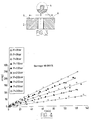
- les figures 4 à 6 sont des graphes illustrant les mesures réalisables à l'aide de l'appareil suivant l'invention.
- mise en charge de l'appareil par activation des moyens de serrage 5, 6, 6a,
- mise en circulation d'un solvant (éthanol) dans le circuit 21, ce circuit contenant environ 25 cl d'éthanol et d'étalon interne, par exemple du propanol, à raison de 2% en masse.
- mise en pression du fluide (soluté) contenu dans l'enceinte 1, à l'aide des moyens 9, 10, 11, 11a.
- l'évolution de la masse m de soluté dans le solvant en fonction du temps, sous un effort de serrage de 10.000 N, pour diverses valeurs de la pression du soluté,
- l'évolution du débit massique Q de fuite en fonction de cette pression, pour diverses valeurs de l'effort de serrage appliqué (de 10kN à 30kN), et
- l'évolution du débit massique Q en fonction de l'effort de serrage exercé.
Claims (11)
- Appareil de mesure du débit de fuite d'un dispositif d'étanchéité d'une enceinte (1) sous pression d'un premier fluide, ladite enceinte (1) étant délimitée par au moins deux pièces (2, 3) accolées et serrées l'une contre l'autre suivant deux surfaces en regard entourant ladite enceinte (1) et constituant ledit dispositif, une fraction dudit premier fluide sous pression étant susceptible de sortir de ladite enceinte (1) en passant entre lesdites surfaces, cet appareil comprenant a) des moyens (21, 22, 23) pour introduire ladite fraction dudit premier fluide dans un deuxième fluide et b) des moyens (24, 25) pour mesurer la quantité dudit premier fluide collectée par ledit deuxième fluide,
caractérisé en ce que lesdits moyens d'introduction (21, 22, 23) assurent une circulation en boucle fermée dudit deuxième fluide, propre à collecter par balayage ladite fraction dudit premier fluide. - Appareil conforme à la revendication 1, caractérisé en ce que lesdits moyens d'introduction comprennent une chambre (23) s'étendant autour de ladite enceinte (1) pour récupérer ladite fraction dudit premier fluide.
- Appareil conforme à l'une des revendications 1 ou 2, caractérisé en ce que lesdits moyens de mesure (24, 25) comprennent des moyens (24) de prélèvement d'un échantillon dudit deuxième fluide et des moyens d'analyse (25) par chromatographie en phase gazeuse de la composition dudit échantillon, pour mesurer la quantité du premier fluide comprise dans le deuxième fluide.
- Appareil conforme à la revendication 3, caractérisé en ce que ledit échantillon contient une masse d'un étalon interne, dans un rapport de masse à celle dudit échantillon précisément déterminé.
- Appareil conforme à l'une quelconque des revendications précédentes, caractérisé en ce qu'il comprend des moyens (6, 6a) pour faire varier l'effort de serrage desdites surfaces et des moyens (13) pour mesurer ledit effort.
- Appareil conforme à l'une quelconque des revendications précédentes, caractérisé en ce qu'il comprend des moyens (9, 10, 11, 11a) pour faire varier la pression dudit premier fluide dans ladite enceinte (1) et des moyens (14) pour mesurer ladite pression.
- Appareil conforme à l'une quelconque des revendications précédentes, caractérisé en ce que ladite enceinte (1) est limitée par deux faces en regard desdites pièces (2, 3), entourées par lesdites surfaces en regard accolées de ces pièces.
- Appareil conforme à la revendication 7, caractérisé en ce que lesdites faces en regard sont délimitées par un contour fermé duquel déborde une nervure (4) formée dans au moins une desdites pièces (2, 3) pour s'appuyer sous pression de serrage contre l'autre pièce.
- Appareil conforme à la revendication 8, caractérisé en ce que ladite nervure (4) présente une section droite sensiblement rectangulaire.
- Appareil conforme à l'une quelconque des revendications précédentes, caractérisé en ce qu'il est thermostaté par des moyens de régulation de température.
- Appareil conforme à l'une quelconque des revendications précédentes, caractérisé en ce qu'il comprend des moyens (18a, 18b) pour observer la zone de contact entre les surfaces en regard desdites pièces (2, 3).
Applications Claiming Priority (2)
| Application Number | Priority Date | Filing Date | Title |
|---|---|---|---|
| FR0201930A FR2836225B1 (fr) | 2002-02-15 | 2002-02-15 | Appareil de mesure du debit de fuite d'un dispositif d'etancheite |
| FR0201930 | 2002-02-15 |
Publications (2)
| Publication Number | Publication Date |
|---|---|
| EP1336831A1 true EP1336831A1 (fr) | 2003-08-20 |
| EP1336831B1 EP1336831B1 (fr) | 2008-04-30 |
Family
ID=27620241
Family Applications (1)
| Application Number | Title | Priority Date | Filing Date |
|---|---|---|---|
| EP03290358A Expired - Lifetime EP1336831B1 (fr) | 2002-02-15 | 2003-02-14 | Appareil de mesure du débit de fuite d'un dispositif d'étanchéité |
Country Status (4)
| Country | Link |
|---|---|
| EP (1) | EP1336831B1 (fr) |
| AT (1) | ATE393908T1 (fr) |
| DE (1) | DE60320601T2 (fr) |
| FR (1) | FR2836225B1 (fr) |
Cited By (3)
| Publication number | Priority date | Publication date | Assignee | Title |
|---|---|---|---|---|
| WO2009010458A3 (fr) * | 2007-07-13 | 2009-04-02 | Deutsch Zentr Luft & Raumfahrt | Dispositif et procédé de test d'un joint d'étanchéité prévu pour des applications à basse température |
| CN103454043A (zh) * | 2013-07-31 | 2013-12-18 | 哈尔滨东安汽车发动机制造有限公司 | 自动变速器控制阀体自泄漏量测量装置 |
| CN117249943A (zh) * | 2023-11-16 | 2023-12-19 | 中汽研汽车检验中心(天津)有限公司 | 一种油泵密封圈耐渗透试验装置及测试方法 |
Citations (2)
| Publication number | Priority date | Publication date | Assignee | Title |
|---|---|---|---|---|
| US5375453A (en) * | 1993-08-31 | 1994-12-27 | Westinghouse Electric Corporation | Assembly for evaluating gasket service life and method for performing the same |
| DE19652514A1 (de) * | 1996-12-17 | 1998-06-18 | Schmidt Traub Henner Prof Dr I | Meßverfahren zur kontinuierlichen Ermittlung der Emissionen an Flanschverbindungen |
-
2002
- 2002-02-15 FR FR0201930A patent/FR2836225B1/fr not_active Expired - Fee Related
-
2003
- 2003-02-14 DE DE60320601T patent/DE60320601T2/de not_active Expired - Lifetime
- 2003-02-14 EP EP03290358A patent/EP1336831B1/fr not_active Expired - Lifetime
- 2003-02-14 AT AT03290358T patent/ATE393908T1/de not_active IP Right Cessation
Patent Citations (2)
| Publication number | Priority date | Publication date | Assignee | Title |
|---|---|---|---|---|
| US5375453A (en) * | 1993-08-31 | 1994-12-27 | Westinghouse Electric Corporation | Assembly for evaluating gasket service life and method for performing the same |
| DE19652514A1 (de) * | 1996-12-17 | 1998-06-18 | Schmidt Traub Henner Prof Dr I | Meßverfahren zur kontinuierlichen Ermittlung der Emissionen an Flanschverbindungen |
Cited By (4)
| Publication number | Priority date | Publication date | Assignee | Title |
|---|---|---|---|---|
| WO2009010458A3 (fr) * | 2007-07-13 | 2009-04-02 | Deutsch Zentr Luft & Raumfahrt | Dispositif et procédé de test d'un joint d'étanchéité prévu pour des applications à basse température |
| CN103454043A (zh) * | 2013-07-31 | 2013-12-18 | 哈尔滨东安汽车发动机制造有限公司 | 自动变速器控制阀体自泄漏量测量装置 |
| CN117249943A (zh) * | 2023-11-16 | 2023-12-19 | 中汽研汽车检验中心(天津)有限公司 | 一种油泵密封圈耐渗透试验装置及测试方法 |
| CN117249943B (zh) * | 2023-11-16 | 2024-03-22 | 中汽研汽车检验中心(天津)有限公司 | 一种油泵密封圈耐渗透试验装置及测试方法 |
Also Published As
| Publication number | Publication date |
|---|---|
| FR2836225A1 (fr) | 2003-08-22 |
| DE60320601D1 (de) | 2008-06-12 |
| ATE393908T1 (de) | 2008-05-15 |
| FR2836225B1 (fr) | 2004-05-28 |
| EP1336831B1 (fr) | 2008-04-30 |
| DE60320601T2 (de) | 2009-05-28 |
Similar Documents
| Publication | Publication Date | Title |
|---|---|---|
| US6968728B2 (en) | Test tap adapter for extracting dissolved gases from insulating oil and measuring electrical parameters of a transformer bushing | |
| WO2023057579A1 (fr) | Dispositif de test d'etancheite et methode associee | |
| FR2782804A1 (fr) | Dispositif de separation et de mesure du volume des differentes phases d'un melange de fluides | |
| EP1336831B1 (fr) | Appareil de mesure du débit de fuite d'un dispositif d'étanchéité | |
| CA2133296C (fr) | Appareil de mesure de caracteristiques thermodynamiques d'un echantillon d'hydrocarbures | |
| EP0806648A1 (fr) | Dipositif de prise d'échantillon sur une canalisation | |
| FR2905176A1 (fr) | Dispositif et procede de test d'etancheite d'articles. | |
| EP1967268B1 (fr) | Collerette en verre solidaire de la branche latérale de la colonne du ballon de distillation | |
| FR3052557A1 (fr) | Systeme de prelevement et d'analyse d'un echantillon gazeux | |
| JPH05256756A (ja) | 連続流メンブレンオスモメータ | |
| WO2021058738A1 (fr) | Capteur de pression differentielle et dispositif de detection comprenant un tel capteur | |
| US5198094A (en) | Counterflow device to reduce the negative impact of contaminating materials used in moisture sensitive apparatuses or procedures | |
| FR3122732A1 (fr) | Membrane pour l’insertion d’un matériau poreux | |
| EP0272983A1 (fr) | Dispositif d'étanchéité d'une enceinte contenant un fluide dilatable, notamment dans un ensemble de connexion électrique | |
| CN117249943B (zh) | 一种油泵密封圈耐渗透试验装置及测试方法 | |
| CN213580643U (zh) | 一种用于液体检测的衰减全反射红外光谱流通池 | |
| WO2000014509A1 (fr) | Dispositif pour la determination, dans des conditions de temperature et de pression extremes, des relations entre pression, volume et temperature d'un corps pur et/ou d'un melange | |
| CA2835021A1 (fr) | Procede de mesure de la viscosite d'un fluide et viscosimetre | |
| FR2479466A1 (fr) | Dispositif d'injection d'echantillons d'un produit gazeux ou liquide sous pression en vue d'analyse | |
| FR3071303A1 (fr) | Systeme de connexion entre un organe de distribution et un organe de reception et procede de detection de fuite | |
| FR2670894A1 (fr) | Procede et dispositif de determination du taux de gaz dans un liquide. | |
| CH430278A (fr) | Installation de chromatographie | |
| Cane | II Vacuum Apparatus and Auxiliaries II Abstract No. | |
| FR2625319A1 (fr) | Dispositif incorporant une electrode de reference pour la mesure de donnees electrochimiques | |
| FR2785387A1 (fr) | Procede et dispositif de mesure non destructive de la pression interne d'un crayon combustible |
Legal Events
| Date | Code | Title | Description |
|---|---|---|---|
| PUAI | Public reference made under article 153(3) epc to a published international application that has entered the european phase |
Free format text: ORIGINAL CODE: 0009012 |
|
| AK | Designated contracting states |
Designated state(s): AT BE BG CH CY CZ DE DK EE ES FI FR GB GR HU IE IT LI LU MC NL PT SE SI SK TR |
|
| AX | Request for extension of the european patent |
Extension state: AL LT LV MK RO |
|
| 17P | Request for examination filed |
Effective date: 20040120 |
|
| AKX | Designation fees paid |
Designated state(s): AT BE BG CH CY CZ DE DK EE ES FI FR GB GR HU IE IT LI LU MC NL PT SE SI SK TR |
|
| GRAP | Despatch of communication of intention to grant a patent |
Free format text: ORIGINAL CODE: EPIDOSNIGR1 |
|
| GRAJ | Information related to disapproval of communication of intention to grant by the applicant or resumption of examination proceedings by the epo deleted |
Free format text: ORIGINAL CODE: EPIDOSDIGR1 |
|
| RIN1 | Information on inventor provided before grant (corrected) |
Inventor name: MARIE, CHRISTOPHE Inventor name: LASSEUX, DIDIER |
|
| 17Q | First examination report despatched |
Effective date: 20060828 |
|
| 17Q | First examination report despatched |
Effective date: 20060828 |
|
| 17Q | First examination report despatched |
Effective date: 20060828 |
|
| GRAP | Despatch of communication of intention to grant a patent |
Free format text: ORIGINAL CODE: EPIDOSNIGR1 |
|
| GRAS | Grant fee paid |
Free format text: ORIGINAL CODE: EPIDOSNIGR3 |
|
| GRAA | (expected) grant |
Free format text: ORIGINAL CODE: 0009210 |
|
| AK | Designated contracting states |
Kind code of ref document: B1 Designated state(s): AT BE BG CH CY CZ DE DK EE ES FI FR GB GR HU IE IT LI LU MC NL PT SE SI SK TR |
|
| REG | Reference to a national code |
Ref country code: GB Ref legal event code: FG4D Free format text: NOT ENGLISH |
|
| REG | Reference to a national code |
Ref country code: CH Ref legal event code: EP |
|
| REG | Reference to a national code |
Ref country code: IE Ref legal event code: FG4D |
|
| REF | Corresponds to: |
Ref document number: 60320601 Country of ref document: DE Date of ref document: 20080612 Kind code of ref document: P |
|
| PG25 | Lapsed in a contracting state [announced via postgrant information from national office to epo] |
Ref country code: SI Free format text: LAPSE BECAUSE OF FAILURE TO SUBMIT A TRANSLATION OF THE DESCRIPTION OR TO PAY THE FEE WITHIN THE PRESCRIBED TIME-LIMIT Effective date: 20080430 |
|
| PG25 | Lapsed in a contracting state [announced via postgrant information from national office to epo] |
Ref country code: PT Free format text: LAPSE BECAUSE OF FAILURE TO SUBMIT A TRANSLATION OF THE DESCRIPTION OR TO PAY THE FEE WITHIN THE PRESCRIBED TIME-LIMIT Effective date: 20080930 Ref country code: ES Free format text: LAPSE BECAUSE OF FAILURE TO SUBMIT A TRANSLATION OF THE DESCRIPTION OR TO PAY THE FEE WITHIN THE PRESCRIBED TIME-LIMIT Effective date: 20080810 Ref country code: BG Free format text: LAPSE BECAUSE OF FAILURE TO SUBMIT A TRANSLATION OF THE DESCRIPTION OR TO PAY THE FEE WITHIN THE PRESCRIBED TIME-LIMIT Effective date: 20080730 Ref country code: FI Free format text: LAPSE BECAUSE OF FAILURE TO SUBMIT A TRANSLATION OF THE DESCRIPTION OR TO PAY THE FEE WITHIN THE PRESCRIBED TIME-LIMIT Effective date: 20080430 |
|
| PG25 | Lapsed in a contracting state [announced via postgrant information from national office to epo] |
Ref country code: AT Free format text: LAPSE BECAUSE OF FAILURE TO SUBMIT A TRANSLATION OF THE DESCRIPTION OR TO PAY THE FEE WITHIN THE PRESCRIBED TIME-LIMIT Effective date: 20080430 |
|
| PG25 | Lapsed in a contracting state [announced via postgrant information from national office to epo] |
Ref country code: DK Free format text: LAPSE BECAUSE OF FAILURE TO SUBMIT A TRANSLATION OF THE DESCRIPTION OR TO PAY THE FEE WITHIN THE PRESCRIBED TIME-LIMIT Effective date: 20080430 Ref country code: CZ Free format text: LAPSE BECAUSE OF FAILURE TO SUBMIT A TRANSLATION OF THE DESCRIPTION OR TO PAY THE FEE WITHIN THE PRESCRIBED TIME-LIMIT Effective date: 20080430 Ref country code: SE Free format text: LAPSE BECAUSE OF FAILURE TO SUBMIT A TRANSLATION OF THE DESCRIPTION OR TO PAY THE FEE WITHIN THE PRESCRIBED TIME-LIMIT Effective date: 20080731 |
|
| PG25 | Lapsed in a contracting state [announced via postgrant information from national office to epo] |
Ref country code: SK Free format text: LAPSE BECAUSE OF FAILURE TO SUBMIT A TRANSLATION OF THE DESCRIPTION OR TO PAY THE FEE WITHIN THE PRESCRIBED TIME-LIMIT Effective date: 20080430 |
|
| PLBE | No opposition filed within time limit |
Free format text: ORIGINAL CODE: 0009261 |
|
| STAA | Information on the status of an ep patent application or granted ep patent |
Free format text: STATUS: NO OPPOSITION FILED WITHIN TIME LIMIT |
|
| 26N | No opposition filed |
Effective date: 20090202 |
|
| PG25 | Lapsed in a contracting state [announced via postgrant information from national office to epo] |
Ref country code: EE Free format text: LAPSE BECAUSE OF FAILURE TO SUBMIT A TRANSLATION OF THE DESCRIPTION OR TO PAY THE FEE WITHIN THE PRESCRIBED TIME-LIMIT Effective date: 20080430 |
|
| BERE | Be: lapsed |
Owner name: CENTRE NATIONAL D'ETUDES SPATIALES Effective date: 20090228 |
|
| PG25 | Lapsed in a contracting state [announced via postgrant information from national office to epo] |
Ref country code: MC Free format text: LAPSE BECAUSE OF NON-PAYMENT OF DUE FEES Effective date: 20090228 |
|
| PG25 | Lapsed in a contracting state [announced via postgrant information from national office to epo] |
Ref country code: BE Free format text: LAPSE BECAUSE OF NON-PAYMENT OF DUE FEES Effective date: 20090228 |
|
| PG25 | Lapsed in a contracting state [announced via postgrant information from national office to epo] |
Ref country code: GR Free format text: LAPSE BECAUSE OF FAILURE TO SUBMIT A TRANSLATION OF THE DESCRIPTION OR TO PAY THE FEE WITHIN THE PRESCRIBED TIME-LIMIT Effective date: 20080731 |
|
| PG25 | Lapsed in a contracting state [announced via postgrant information from national office to epo] |
Ref country code: LU Free format text: LAPSE BECAUSE OF NON-PAYMENT OF DUE FEES Effective date: 20090214 |
|
| PG25 | Lapsed in a contracting state [announced via postgrant information from national office to epo] |
Ref country code: HU Free format text: LAPSE BECAUSE OF FAILURE TO SUBMIT A TRANSLATION OF THE DESCRIPTION OR TO PAY THE FEE WITHIN THE PRESCRIBED TIME-LIMIT Effective date: 20081101 |
|
| PG25 | Lapsed in a contracting state [announced via postgrant information from national office to epo] |
Ref country code: TR Free format text: LAPSE BECAUSE OF FAILURE TO SUBMIT A TRANSLATION OF THE DESCRIPTION OR TO PAY THE FEE WITHIN THE PRESCRIBED TIME-LIMIT Effective date: 20080430 |
|
| PG25 | Lapsed in a contracting state [announced via postgrant information from national office to epo] |
Ref country code: CY Free format text: LAPSE BECAUSE OF FAILURE TO SUBMIT A TRANSLATION OF THE DESCRIPTION OR TO PAY THE FEE WITHIN THE PRESCRIBED TIME-LIMIT Effective date: 20080430 |
|
| REG | Reference to a national code |
Ref country code: FR Ref legal event code: PLFP Year of fee payment: 14 |
|
| PGFP | Annual fee paid to national office [announced via postgrant information from national office to epo] |
Ref country code: NL Payment date: 20160113 Year of fee payment: 14 |
|
| PGFP | Annual fee paid to national office [announced via postgrant information from national office to epo] |
Ref country code: IE Payment date: 20160118 Year of fee payment: 14 Ref country code: DE Payment date: 20160212 Year of fee payment: 14 Ref country code: CH Payment date: 20160208 Year of fee payment: 14 Ref country code: IT Payment date: 20160212 Year of fee payment: 14 |
|
| PGFP | Annual fee paid to national office [announced via postgrant information from national office to epo] |
Ref country code: FR Payment date: 20160229 Year of fee payment: 14 Ref country code: GB Payment date: 20160216 Year of fee payment: 14 |
|
| REG | Reference to a national code |
Ref country code: DE Ref legal event code: R119 Ref document number: 60320601 Country of ref document: DE |
|
| REG | Reference to a national code |
Ref country code: CH Ref legal event code: PL |
|
| REG | Reference to a national code |
Ref country code: NL Ref legal event code: MM Effective date: 20170301 |
|
| GBPC | Gb: european patent ceased through non-payment of renewal fee |
Effective date: 20170214 |
|
| PG25 | Lapsed in a contracting state [announced via postgrant information from national office to epo] |
Ref country code: CH Free format text: LAPSE BECAUSE OF NON-PAYMENT OF DUE FEES Effective date: 20170228 Ref country code: LI Free format text: LAPSE BECAUSE OF NON-PAYMENT OF DUE FEES Effective date: 20170228 |
|
| REG | Reference to a national code |
Ref country code: IE Ref legal event code: MM4A |
|
| PG25 | Lapsed in a contracting state [announced via postgrant information from national office to epo] |
Ref country code: NL Free format text: LAPSE BECAUSE OF NON-PAYMENT OF DUE FEES Effective date: 20170301 |
|
| REG | Reference to a national code |
Ref country code: FR Ref legal event code: ST Effective date: 20171031 |
|
| PG25 | Lapsed in a contracting state [announced via postgrant information from national office to epo] |
Ref country code: FR Free format text: LAPSE BECAUSE OF NON-PAYMENT OF DUE FEES Effective date: 20170228 Ref country code: DE Free format text: LAPSE BECAUSE OF NON-PAYMENT OF DUE FEES Effective date: 20170901 |
|
| PG25 | Lapsed in a contracting state [announced via postgrant information from national office to epo] |
Ref country code: IT Free format text: LAPSE BECAUSE OF NON-PAYMENT OF DUE FEES Effective date: 20170214 Ref country code: IE Free format text: LAPSE BECAUSE OF NON-PAYMENT OF DUE FEES Effective date: 20170214 Ref country code: GB Free format text: LAPSE BECAUSE OF NON-PAYMENT OF DUE FEES Effective date: 20170214 |