EP1336810A2 - Joining structure of piping to a flange - Google Patents
Joining structure of piping to a flange Download PDFInfo
- Publication number
- EP1336810A2 EP1336810A2 EP03250391A EP03250391A EP1336810A2 EP 1336810 A2 EP1336810 A2 EP 1336810A2 EP 03250391 A EP03250391 A EP 03250391A EP 03250391 A EP03250391 A EP 03250391A EP 1336810 A2 EP1336810 A2 EP 1336810A2
- Authority
- EP
- European Patent Office
- Prior art keywords
- flange
- pipe
- inner pipe
- hole
- joining
- Prior art date
- Legal status (The legal status is an assumption and is not a legal conclusion. Google has not performed a legal analysis and makes no representation as to the accuracy of the status listed.)
- Granted
Links
Images


Classifications
-
- F—MECHANICAL ENGINEERING; LIGHTING; HEATING; WEAPONS; BLASTING
- F28—HEAT EXCHANGE IN GENERAL
- F28D—HEAT-EXCHANGE APPARATUS, NOT PROVIDED FOR IN ANOTHER SUBCLASS, IN WHICH THE HEAT-EXCHANGE MEDIA DO NOT COME INTO DIRECT CONTACT
- F28D7/00—Heat-exchange apparatus having stationary tubular conduit assemblies for both heat-exchange media, the media being in contact with different sides of a conduit wall
- F28D7/10—Heat-exchange apparatus having stationary tubular conduit assemblies for both heat-exchange media, the media being in contact with different sides of a conduit wall the conduits being arranged one within the other, e.g. concentrically
- F28D7/106—Heat-exchange apparatus having stationary tubular conduit assemblies for both heat-exchange media, the media being in contact with different sides of a conduit wall the conduits being arranged one within the other, e.g. concentrically consisting of two coaxial conduits or modules of two coaxial conduits
-
- F—MECHANICAL ENGINEERING; LIGHTING; HEATING; WEAPONS; BLASTING
- F01—MACHINES OR ENGINES IN GENERAL; ENGINE PLANTS IN GENERAL; STEAM ENGINES
- F01N—GAS-FLOW SILENCERS OR EXHAUST APPARATUS FOR MACHINES OR ENGINES IN GENERAL; GAS-FLOW SILENCERS OR EXHAUST APPARATUS FOR INTERNAL COMBUSTION ENGINES
- F01N3/00—Exhaust or silencing apparatus having means for purifying, rendering innocuous, or otherwise treating exhaust
- F01N3/02—Exhaust or silencing apparatus having means for purifying, rendering innocuous, or otherwise treating exhaust for cooling, or for removing solid constituents of, exhaust
- F01N3/0205—Exhaust or silencing apparatus having means for purifying, rendering innocuous, or otherwise treating exhaust for cooling, or for removing solid constituents of, exhaust using heat exchangers
-
- F—MECHANICAL ENGINEERING; LIGHTING; HEATING; WEAPONS; BLASTING
- F01—MACHINES OR ENGINES IN GENERAL; ENGINE PLANTS IN GENERAL; STEAM ENGINES
- F01N—GAS-FLOW SILENCERS OR EXHAUST APPARATUS FOR MACHINES OR ENGINES IN GENERAL; GAS-FLOW SILENCERS OR EXHAUST APPARATUS FOR INTERNAL COMBUSTION ENGINES
- F01N3/00—Exhaust or silencing apparatus having means for purifying, rendering innocuous, or otherwise treating exhaust
- F01N3/02—Exhaust or silencing apparatus having means for purifying, rendering innocuous, or otherwise treating exhaust for cooling, or for removing solid constituents of, exhaust
- F01N3/04—Exhaust or silencing apparatus having means for purifying, rendering innocuous, or otherwise treating exhaust for cooling, or for removing solid constituents of, exhaust using liquids
- F01N3/043—Exhaust or silencing apparatus having means for purifying, rendering innocuous, or otherwise treating exhaust for cooling, or for removing solid constituents of, exhaust using liquids without contact between liquid and exhaust gases
-
- F—MECHANICAL ENGINEERING; LIGHTING; HEATING; WEAPONS; BLASTING
- F02—COMBUSTION ENGINES; HOT-GAS OR COMBUSTION-PRODUCT ENGINE PLANTS
- F02M—SUPPLYING COMBUSTION ENGINES IN GENERAL WITH COMBUSTIBLE MIXTURES OR CONSTITUENTS THEREOF
- F02M26/00—Engine-pertinent apparatus for adding exhaust gases to combustion-air, main fuel or fuel-air mixture, e.g. by exhaust gas recirculation [EGR] systems
- F02M26/11—Manufacture or assembly of EGR systems; Materials or coatings specially adapted for EGR systems
-
- F—MECHANICAL ENGINEERING; LIGHTING; HEATING; WEAPONS; BLASTING
- F02—COMBUSTION ENGINES; HOT-GAS OR COMBUSTION-PRODUCT ENGINE PLANTS
- F02M—SUPPLYING COMBUSTION ENGINES IN GENERAL WITH COMBUSTIBLE MIXTURES OR CONSTITUENTS THEREOF
- F02M26/00—Engine-pertinent apparatus for adding exhaust gases to combustion-air, main fuel or fuel-air mixture, e.g. by exhaust gas recirculation [EGR] systems
- F02M26/12—Engine-pertinent apparatus for adding exhaust gases to combustion-air, main fuel or fuel-air mixture, e.g. by exhaust gas recirculation [EGR] systems characterised by means for attaching parts of an EGR system to each other or to engine parts
-
- F—MECHANICAL ENGINEERING; LIGHTING; HEATING; WEAPONS; BLASTING
- F02—COMBUSTION ENGINES; HOT-GAS OR COMBUSTION-PRODUCT ENGINE PLANTS
- F02M—SUPPLYING COMBUSTION ENGINES IN GENERAL WITH COMBUSTIBLE MIXTURES OR CONSTITUENTS THEREOF
- F02M26/00—Engine-pertinent apparatus for adding exhaust gases to combustion-air, main fuel or fuel-air mixture, e.g. by exhaust gas recirculation [EGR] systems
- F02M26/13—Arrangement or layout of EGR passages, e.g. in relation to specific engine parts or for incorporation of accessories
- F02M26/22—Arrangement or layout of EGR passages, e.g. in relation to specific engine parts or for incorporation of accessories with coolers in the recirculation passage
- F02M26/29—Constructional details of the coolers, e.g. pipes, plates, ribs, insulation or materials
- F02M26/32—Liquid-cooled heat exchangers
-
- F—MECHANICAL ENGINEERING; LIGHTING; HEATING; WEAPONS; BLASTING
- F16—ENGINEERING ELEMENTS AND UNITS; GENERAL MEASURES FOR PRODUCING AND MAINTAINING EFFECTIVE FUNCTIONING OF MACHINES OR INSTALLATIONS; THERMAL INSULATION IN GENERAL
- F16L—PIPES; JOINTS OR FITTINGS FOR PIPES; SUPPORTS FOR PIPES, CABLES OR PROTECTIVE TUBING; MEANS FOR THERMAL INSULATION IN GENERAL
- F16L39/00—Joints or fittings for double-walled or multi-channel pipes or pipe assemblies
- F16L39/005—Joints or fittings for double-walled or multi-channel pipes or pipe assemblies for concentric pipes
-
- F—MECHANICAL ENGINEERING; LIGHTING; HEATING; WEAPONS; BLASTING
- F28—HEAT EXCHANGE IN GENERAL
- F28F—DETAILS OF HEAT-EXCHANGE AND HEAT-TRANSFER APPARATUS, OF GENERAL APPLICATION
- F28F9/00—Casings; Header boxes; Auxiliary supports for elements; Auxiliary members within casings
- F28F9/02—Header boxes; End plates
- F28F9/0219—Arrangements for sealing end plates into casing or header box; Header box sub-elements
-
- F—MECHANICAL ENGINEERING; LIGHTING; HEATING; WEAPONS; BLASTING
- F01—MACHINES OR ENGINES IN GENERAL; ENGINE PLANTS IN GENERAL; STEAM ENGINES
- F01N—GAS-FLOW SILENCERS OR EXHAUST APPARATUS FOR MACHINES OR ENGINES IN GENERAL; GAS-FLOW SILENCERS OR EXHAUST APPARATUS FOR INTERNAL COMBUSTION ENGINES
- F01N13/00—Exhaust or silencing apparatus characterised by constructional features ; Exhaust or silencing apparatus, or parts thereof, having pertinent characteristics not provided for in, or of interest apart from, groups F01N1/00 - F01N5/00, F01N9/00, F01N11/00
- F01N13/08—Other arrangements or adaptations of exhaust conduits
-
- F—MECHANICAL ENGINEERING; LIGHTING; HEATING; WEAPONS; BLASTING
- F01—MACHINES OR ENGINES IN GENERAL; ENGINE PLANTS IN GENERAL; STEAM ENGINES
- F01N—GAS-FLOW SILENCERS OR EXHAUST APPARATUS FOR MACHINES OR ENGINES IN GENERAL; GAS-FLOW SILENCERS OR EXHAUST APPARATUS FOR INTERNAL COMBUSTION ENGINES
- F01N13/00—Exhaust or silencing apparatus characterised by constructional features ; Exhaust or silencing apparatus, or parts thereof, having pertinent characteristics not provided for in, or of interest apart from, groups F01N1/00 - F01N5/00, F01N9/00, F01N11/00
- F01N13/18—Construction facilitating manufacture, assembly, or disassembly
- F01N13/1805—Fixing exhaust manifolds, exhaust pipes or pipe sections to each other, to engine or to vehicle body
-
- F—MECHANICAL ENGINEERING; LIGHTING; HEATING; WEAPONS; BLASTING
- F01—MACHINES OR ENGINES IN GENERAL; ENGINE PLANTS IN GENERAL; STEAM ENGINES
- F01N—GAS-FLOW SILENCERS OR EXHAUST APPARATUS FOR MACHINES OR ENGINES IN GENERAL; GAS-FLOW SILENCERS OR EXHAUST APPARATUS FOR INTERNAL COMBUSTION ENGINES
- F01N13/00—Exhaust or silencing apparatus characterised by constructional features ; Exhaust or silencing apparatus, or parts thereof, having pertinent characteristics not provided for in, or of interest apart from, groups F01N1/00 - F01N5/00, F01N9/00, F01N11/00
- F01N13/18—Construction facilitating manufacture, assembly, or disassembly
- F01N13/1838—Construction facilitating manufacture, assembly, or disassembly characterised by the type of connection between parts of exhaust or silencing apparatus, e.g. between housing and tubes, between tubes and baffles
-
- F—MECHANICAL ENGINEERING; LIGHTING; HEATING; WEAPONS; BLASTING
- F01—MACHINES OR ENGINES IN GENERAL; ENGINE PLANTS IN GENERAL; STEAM ENGINES
- F01N—GAS-FLOW SILENCERS OR EXHAUST APPARATUS FOR MACHINES OR ENGINES IN GENERAL; GAS-FLOW SILENCERS OR EXHAUST APPARATUS FOR INTERNAL COMBUSTION ENGINES
- F01N2450/00—Methods or apparatus for fitting, inserting or repairing different elements
- F01N2450/22—Methods or apparatus for fitting, inserting or repairing different elements by welding or brazing
-
- F—MECHANICAL ENGINEERING; LIGHTING; HEATING; WEAPONS; BLASTING
- F01—MACHINES OR ENGINES IN GENERAL; ENGINE PLANTS IN GENERAL; STEAM ENGINES
- F01N—GAS-FLOW SILENCERS OR EXHAUST APPARATUS FOR MACHINES OR ENGINES IN GENERAL; GAS-FLOW SILENCERS OR EXHAUST APPARATUS FOR INTERNAL COMBUSTION ENGINES
- F01N2470/00—Structure or shape of gas passages, pipes or tubes
- F01N2470/24—Concentric tubes or tubes being concentric to housing, e.g. telescopically assembled
-
- F—MECHANICAL ENGINEERING; LIGHTING; HEATING; WEAPONS; BLASTING
- F28—HEAT EXCHANGE IN GENERAL
- F28F—DETAILS OF HEAT-EXCHANGE AND HEAT-TRANSFER APPARATUS, OF GENERAL APPLICATION
- F28F2275/00—Fastening; Joining
- F28F2275/20—Fastening; Joining with threaded elements
-
- Y—GENERAL TAGGING OF NEW TECHNOLOGICAL DEVELOPMENTS; GENERAL TAGGING OF CROSS-SECTIONAL TECHNOLOGIES SPANNING OVER SEVERAL SECTIONS OF THE IPC; TECHNICAL SUBJECTS COVERED BY FORMER USPC CROSS-REFERENCE ART COLLECTIONS [XRACs] AND DIGESTS
- Y02—TECHNOLOGIES OR APPLICATIONS FOR MITIGATION OR ADAPTATION AGAINST CLIMATE CHANGE
- Y02T—CLIMATE CHANGE MITIGATION TECHNOLOGIES RELATED TO TRANSPORTATION
- Y02T10/00—Road transport of goods or passengers
- Y02T10/10—Internal combustion engine [ICE] based vehicles
- Y02T10/12—Improving ICE efficiencies
Definitions
- the present invention relates to a joining structure of piping to a flange, which piping constitute a passage for oil, blowby gas, fuel, EGR, or the like in an internal combustion engine.
- an inner pipe joining hole 20 and a through hole 22 there are formed an inner pipe joining hole 20 and a through hole 22.
- a branch pipe joining hole 23 On the front surface 4a of the flange 4 is formed a branch pipe joining hole 23 at the end of the through hole 22 and further formed bolt holes 25, 25 for the bolt 15. From this front surface 4a the inner pipe 7 and branch pipe 8a are respectively inserted into the joining holes 20, 23 and fixed by brazing or welding.
- the inner pipe 7 of the dual-pipe 5 carries EGR gas and the outer pipe 6 of the same has a passage R formed around the outer periphery of the inner pipe 7, making the cooling water for an engine pass through the passage R.
- the other end of the double-pipe 5 is connected to an intake manifold 14 and also provided with a branch pipe 11 and a hose 12, which is connected to a suction pipe 13.
- the cooling water in the outer pipe 6 is returned through the suction pipe 13 to a water pump.
- the through hole 22 for cooling water is provided in the flange 4 and the cooling water is introduced into the double-pipe 5 by the use of the branch pipe 8a or hose 9. Accordingly, there is a problem that the need of the branch pipe, hose, etc has raised the cost.
- the present invention is worked out in view of the above-described problems in the prior art. It is an object of the present invention to provide a joining structure of piping to a flange wherein the joining work is easy, the strength is secured, and the cost can be decreased.
- the first subject matter of the present invention is that in the piping of a double-pipe structure including an inner pipe to carry a fluid and an outer pipe to carry a coolant through a passage formed around the outer periphery of the inner pipe, the inner and the outer pipe are joined together to a flange.
- the second subject matter of the present invention is that on the flange are formed an inner pipe joining hole communicating only with the inner pipe and a through hole communicating only with the passage.
- the third subject matter is that on the front surface of the flange is formed a recess of the same outer periphery as the outer pipe, the periphery of which recess surrounds the inner pipe joining hole and the through hole, the outer pipe is inserted into the recess and the inner pipe into the inner pipe joining hole, and both pipes are fixed to the flange by means of brazing.
- the double-pipe can be easily joined to the flange by brazing; the inner pipe of the double-pipe can carry a fluid satisfactorily; and the passage between the inner and the outer pipe can well pass a coolant through the through hole.
- the flange comprises a front flange and a back flange; through the back flange are formed an inner pipe joining hole for the inner pipe to be inserted and fixed by brazing and a through hole outside the inner pipe joining hole; through the front flange is formed an outer pipe joining hole of which the periphery surrounds the inner pipe joining hole and the through hole and into which the outer pipe is inserted and fixed by brazing; and the front flange is placed on the back flange and fixed to it by brazing.
- the flange can be made of thin plate, so that it is possible for the flange to be made compact to guarantee the degree of freedom for the formation.
- sectional area in the joined portion of the flange and double-pipe increases to improve the strength.
- the members such as branch pipes, hoses, etc in the past become useless, so that it is possible to decrease the cost because of less number of parts.
- the fifth subject matter is that the inner pipe is inserted into the inner pipe joining hole and fixed to it by brazing, to the front surface of the flange is joined a cone-shaped connecting member of which the periphery surrounds the inner pipe joining hole and the through hole, and the outer pipe is fixed to the connecting member by brazing.
- the invention contemplates the following: a joint for joining a double pipe to a double orifice, e.g. in a flange, a flange adapted for joining to such a double pipe, a double pipe adopted for joining to a double orifice, and to a combination of the double pipe and the flange, and/or a separate joint.
- a joint for joining a double pipe to a double orifice e.g. in a flange, a flange adapted for joining to such a double pipe, a double pipe adopted for joining to a double orifice, and to a combination of the double pipe and the flange, and/or a separate joint.
- the invention also extends to an internal combustion engine incorporating such arrangements.
- FIG. 1 is a perspective view of the relevant parts of a double-pipe structure joined to a flange in the first embodiment.
- FIG.2 is a vertical sectional view of the structure in FIG.1.
- the flange 4 in this case is secured with bolts 15, 15 to the EGR passage 2 that is the same as shown in FIG. 11 referred to above.
- a double-pipe 5 that constitutes an EGR tube is joined to this flange 4.
- the double-pipe 5 is formed in double structure with the inner tube 7 and outer tube 6 outside the tube 7. Between the outside periphery of the inner tube 7 and the inner periphery of the outer tube 6 is formed a passage R to carry water.
- the inner tube 7 carries EGR gas.
- the inner pipe 7 is formed in circular cross section.
- the outer pipe is also formed circular in general cross section, while the end portion of it is widened outside to form a bulging portion 6a. Accordingly, because of the bulging portion 6a, the end portion of the outer pipe 6 is in nearly gourd-shaped section.
- the end of the inner pipe 7 is projected outside from that of the outer pipe 6.
- the dimension of this end projection of the inner pipe 7 is defined to be slightly shorter than the thickness of the flange 4.
- a through hole 22 to carry cooling water
- an outer pipe joining recess 24 is provided on the front surface 4a of the flange 4 in hollow fashion.
- This outer pipe joining recess 24 surrounds the outer periphery of the inner pipe joining hole 20 and through hole 22, having a nearly gourd-shaped outer periphery for the end of the outer pipe 6. Namely, within this outer pipe joining recess 24 formed in hollow fashion in nearly gourd-shaped section, there are pierced the inner pipe joining hole 20 and the through hole 22.
- the outer pipe 6 is inserted into the outer pipe joining recess 24, and the inner pipe 7 into the inner pipe joining hole 20. Then, the outer pipe 6 is brazed to the front surface 4a and the inner pipe 7 is fixed to the inner pipe joining hole 20 by brazing. Namely, the inner pipe 7 and outer pipe 6 are joined together to the flange 4 by brazing.
- the fastening work of the hose 9 becomes unnecessary and there is no stress concentration at the brazed area of the inner pipe 7 as in the prior art, so that the strength increases in this embodiment.
- the brazed area of the inner pipe 7 to the flange 4 can be cooled by circulation of the cooling water from the through hole 22, the use of Ni solder as in the prior art becomes needless, so that it is possible to use inexpensive copper solder, etc for brazing to decrease the cost.
- the second embodiment will be described with reference to the perspective exploded view of FIG.3, the perspective view of the assembly of FIG.4, and the enlarged sectional view of the structure of FIG.5.
- the inner pipe 7 and the outer pipe 6 of the double-pipe 5 are joined together to the flange, except that the flange 4 is composed of a thin front flange 41 and a thick back flange 42.
- the inner pipe 7 is inserted into the inner pipe joining hole 20 of the back flange 42 to be fixed by brazing, and the back flange 42 is placed on the front flange 41 to be joined together by brazing.
- the outer pipe 6 is inserted into the outer pipe joining hole 24A of the front flange 41 to be fixed by brazing, and in this joined condition the outer pipe 6 comes to be arranged outside the through hole 22, so that the cooling water can pass through the through hole 22 into the passage R of the double-pipe 5.
- the formation of a complex outer pipe joining recess 24 on the flange 4 as in the first embodiment is not required, and also the formation of a bulging portion 6a at the end portion of the outer pipe 6 is needless.
- the front flange 41 and back flange 42 can be easily provided in pierced fashion with the joining holes 24A, 20 with true circular periphery, so that the machining cost can be decreased. Further, the members such as hoses 9 in the past become needless, so that the less number of parts makes the cost decrease.
- the fastening work of the hose 9 becomes unnecessary and there is no stress concentration at the brazed area of the inner pipe 7 as in the prior art, so that the strength increases in this embodiment.
- the brazed area of the inner pipe 7 to the flange 4 can be cooled by circulation of the cooling water from the through hole 22, the use of Ni solder as in the prior art becomes needless, so that it is possible to use inexpensive copper solder, etc for brazing to decrease the cost.
- the flange 4 can be made of thin plate, so that it is possible to make the peripheral dimension D of the bolt hole 25 short as shown in the plan view of FIG.6. Namely, though the dimension D should be more than the thickness of the flange plate, the flange 4 can be short in the dimension D owing to the thin plate, so that it is possible for the flange 4 to be made compact to guarantee the degree of freedom for the formation.
- an inner pipe joining hole 20 through a flange 4 there are formed an inner pipe joining hole 20 and a through hole 22, outside which holes 20, 22 are formed bolt holes 25, 25.
- an inner pipe 7 Into the inner pipe joining hole 20 is inserted an inner pipe 7 to be fixed by brazing.
- An outer pipe 6 is joined to the end of a cone-shaped connecting member 30 by brazing.
- the cone-shaped connecting member 30 is formed in a cone-shape that is widened at the bottom and tapered to the top end.
- a connecting rim 30a is projected around the outer periphery at the bottom;
- a shoulder 30b is formed at the upper portion; and
- a connecting cylinder 30c is projected upward from this shoulder 30b.
- the outer pipe 6 is inserted into the outer periphery of this connecting cylinder 30c, and the end of pipe 6 abuts against the shoulder 30b, fixed by brazing.
- the bottom end of the cone-shaped connecting member 30 has the diameter that can surround the periphery of the inner pipe-joining hole 20 and through hole 22.
- the formation of a bulging portion 6a at the end portion of the outer pipe 6 as in the first embodiment is needless.
- the outer pipe 6 can be joined through the cone-shaped connecting member 30 to the flange 4.
- the cooling water is introduced through the through hole 22 into the cone-shaped connecting member 30 and passed through the inside of the connecting cylinder 30c into the passage R of the double-pipe 5. Since the cooling water is circulated also around the brazed area of the inner pipe 7 and flange 4, the brazed area can be well cooled, so that it is possible to guarantee the durability of brazing even by use of inexpensive copper solder.
- the dimension A in FIG.10 may be defined small and the degree of freedom for layout may be attained large.
- EGR passage members for internal combustion engines where an inner pipe 7 may carry EGR gas and a passage R may pass cooling water through
- such constitution as a double-pipe joined to a flange can be adopted also for the joining structure of such piping to a flange as passages for oil, blowby gas, fuel, etc in the internal combustion engines.
- the inner pipe 7 may carry other fluid and the passage R may pass through any coolant for cooling the fluid within the inner pipe 7.
Landscapes
- Engineering & Computer Science (AREA)
- General Engineering & Computer Science (AREA)
- Mechanical Engineering (AREA)
- Chemical & Material Sciences (AREA)
- Combustion & Propulsion (AREA)
- Physics & Mathematics (AREA)
- Thermal Sciences (AREA)
- Manufacturing & Machinery (AREA)
- Quick-Acting Or Multi-Walled Pipe Joints (AREA)
- Branch Pipes, Bends, And The Like (AREA)
- Flanged Joints, Insulating Joints, And Other Joints (AREA)
- Exhaust-Gas Circulating Devices (AREA)
Abstract
Description
- The present invention relates to a joining structure of piping to a flange, which piping constitute a passage for oil, blowby gas, fuel, EGR, or the like in an internal combustion engine.
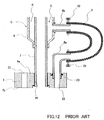
- In a case of the prior art, as shown in Fig. 11 of the attached drawings, on the side of a cylinder head 1 is provided an
EGR passage 2 withEGR valve 3, and on the side of thisEGR passage 2 is secured aflange 4 withbolts flange 4 is joined aninner pipe 7 as the end of a double-pipe 5 that constitutes an EGR tube, and also to theflange 4 is joined abranch pipe 8a parallel to theinner pipe 7. To the end of thisbranch pipe 8a is connected ahose 9 with aclip 10, the other end of whichhose 9 is connected through a clip to abranch pipe 8b that is joined to anouter pipe 6 of the double-pipe 5. - As shown in the enlarged sectional view of FIG.12, through the
flange 4 there are formed an innerpipe joining hole 20 and a throughhole 22. On thefront surface 4a of theflange 4 is formed a branchpipe joining hole 23 at the end of the throughhole 22 and further formedbolt holes bolt 15. From thisfront surface 4a theinner pipe 7 andbranch pipe 8a are respectively inserted into the joiningholes - The
inner pipe 7 of the dual-pipe 5 carries EGR gas and theouter pipe 6 of the same has a passage R formed around the outer periphery of theinner pipe 7, making the cooling water for an engine pass through the passage R. - Incidentally, the other end of the double-
pipe 5 is connected to anintake manifold 14 and also provided with abranch pipe 11 and ahose 12, which is connected to asuction pipe 13. The cooling water in theouter pipe 6 is returned through thesuction pipe 13 to a water pump. - As described above, in the piping structure of the prior art, the through
hole 22 for cooling water is provided in theflange 4 and the cooling water is introduced into the double-pipe 5 by the use of thebranch pipe 8a orhose 9. Accordingly, there is a problem that the need of the branch pipe, hose, etc has raised the cost. - Further, the work to fasten the
hose 9 withclip 10 or the like is required and the need to separate thehose 9 from high temperature portion has been caused. - Still further, there is a problem of strength that the stress concentration is liable to occur on the joined portion of the
inner pipe 7 andflange 4. - Moreover, since the brazed portion of the
inner pipe 7 andflange 4 is exposed to high temperature of EGR gas, it is required to perform the brazing with Ni solder of high heat-resistance. Accordingly, there is a problem of high cost. - Incidentally, the following is a patent document as an example of the reference:
- Unexamined patent publication 2000-130964
-
- The present invention is worked out in view of the above-described problems in the prior art. It is an object of the present invention to provide a joining structure of piping to a flange wherein the joining work is easy, the strength is secured, and the cost can be decreased.
- The first subject matter of the present invention is that in the piping of a double-pipe structure including an inner pipe to carry a fluid and an outer pipe to carry a coolant through a passage formed around the outer periphery of the inner pipe, the inner and the outer pipe are joined together to a flange.
- Thereby, the branch pipes, hoses, etc to carry cooling water become unnecessary, so that it is possible to decrease the cost because of less number of parts. Besides, it is possible to make the piping in a compact structure.
- The second subject matter of the present invention is that on the flange are formed an inner pipe joining hole communicating only with the inner pipe and a through hole communicating only with the passage.
- Accordingly, it is possible to carry the fluid from the inner pipe joining hole of the flange into the inner pipe, and it is possible to lead coolant from the through hole of the flange into the passage of the double-pipe.
- The third subject matter is that on the front surface of the flange is formed a recess of the same outer periphery as the outer pipe, the periphery of which recess surrounds the inner pipe joining hole and the through hole, the outer pipe is inserted into the recess and the inner pipe into the inner pipe joining hole, and both pipes are fixed to the flange by means of brazing.
- Thereby, the double-pipe can be easily joined to the flange by brazing; the inner pipe of the double-pipe can carry a fluid satisfactorily; and the passage between the inner and the outer pipe can well pass a coolant through the through hole.
- The fourth subject matter is that the flange comprises a front flange and a back flange; through the back flange are formed an inner pipe joining hole for the inner pipe to be inserted and fixed by brazing and a through hole outside the inner pipe joining hole; through the front flange is formed an outer pipe joining hole of which the periphery surrounds the inner pipe joining hole and the through hole and into which the outer pipe is inserted and fixed by brazing; and the front flange is placed on the back flange and fixed to it by brazing.
- Owing to adopting the split structure of the flange, the flange can be made of thin plate, so that it is possible for the flange to be made compact to guarantee the degree of freedom for the formation.
- Further, the sectional area in the joined portion of the flange and double-pipe increases to improve the strength. Besides, the members such as branch pipes, hoses, etc in the past become useless, so that it is possible to decrease the cost because of less number of parts.
- The fifth subject matter is that the inner pipe is inserted into the inner pipe joining hole and fixed to it by brazing, to the front surface of the flange is joined a cone-shaped connecting member of which the periphery surrounds the inner pipe joining hole and the through hole, and the outer pipe is fixed to the connecting member by brazing.
- Thereby, the cooling water from the through hole is well circulated around the brazed area, so that it is possible to guarantee the durability of brazing even by use of inexpensive copper solder.
- Further, there is no stress concentration at the joined area of the inner pipe and the flange, so that it is possible to guarantee the strength.
- The invention contemplates the following: a joint for joining a double pipe to a double orifice, e.g. in a flange, a flange adapted for joining to such a double pipe, a double pipe adopted for joining to a double orifice, and to a combination of the double pipe and the flange, and/or a separate joint. The invention also extends to an internal combustion engine incorporating such arrangements.
- The invention will be further described by way of example with reference to the accompanying drawings, in which:-
- Fig. 1 is a perspective view of the relevant parts of a double pipe structure joined to a flange in the first embodiment;
- FIG.2 is a vertical sectional view of the structure in FIG.1;
- FIG.3 is a perspective exploded view of a double-pipe structure, a front and a back flange in the second embodiment;
- FIG.4 is a perspective view of the assembly composed of the members in FIG.3;
- FIG.5 is an enlarged sectional view of the structure in FIG.4;
- FIG.6 is a plan view of a flange in the second embodiment;
- FIG.7 is a perspective view of a flange provided with a stay in the second embodiment;
- FIG.8 is a perspective exploded view of a double-pipe, flange and cone-shaped connecting member in the third embodiment;
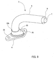
- FIG.9 is a perspective view of an assembly composed of the members in FIG.8;
- FIG.10 is a vertical sectional view of the structure in FIG.9;
- FIG.11 is a perspective view of an engine; and
- FIG.12 is an enlarged sectional view of a conventional joining structure of a flange and double-pipe in the engine of FIG.11.
-
- Hereinafter, an embodiment of the present invention will be described with reference to the drawings.
- FIG. 1 is a perspective view of the relevant parts of a double-pipe structure joined to a flange in the first embodiment. FIG.2 is a vertical sectional view of the structure in FIG.1.
- The
flange 4 in this case is secured withbolts passage 2 that is the same as shown in FIG. 11 referred to above. A double-pipe 5 that constitutes an EGR tube is joined to thisflange 4. The double-pipe 5 is formed in double structure with theinner tube 7 andouter tube 6 outside thetube 7. Between the outside periphery of theinner tube 7 and the inner periphery of theouter tube 6 is formed a passage R to carry water. Theinner tube 7 carries EGR gas. - The
inner pipe 7 is formed in circular cross section. The outer pipe is also formed circular in general cross section, while the end portion of it is widened outside to form a bulgingportion 6a. Accordingly, because of the bulgingportion 6a, the end portion of theouter pipe 6 is in nearly gourd-shaped section. - The end of the
inner pipe 7 is projected outside from that of theouter pipe 6. The dimension of this end projection of theinner pipe 7 is defined to be slightly shorter than the thickness of theflange 4. - On the other hand, through the
flange 4 there is formedbolt holes bolt 15 to be inserted so that theflange 4 may be secured toEGR passage 2. Also, through theflange 4, inside theseholes pipe joining hole 20 for theinner pipe 7 of the double-pipe 5 to be inserted, which joininghole 20 is in circular cross section corresponding to theinner pipe 7. This innerpipe joining hole 20 can make EGR gas pass through. - Further, through the
flange 4 is provided a throughhole 22 to carry cooling water, and on thefront surface 4a of theflange 4 is formed in hollow fashion an outerpipe joining recess 24. - This outer
pipe joining recess 24 surrounds the outer periphery of the innerpipe joining hole 20 and throughhole 22, having a nearly gourd-shaped outer periphery for the end of theouter pipe 6. Namely, within this outerpipe joining recess 24 formed in hollow fashion in nearly gourd-shaped section, there are pierced the innerpipe joining hole 20 and the throughhole 22. - As shown in the sectional view of FIG.2, from the
front surface 4a of theflange 4 theouter pipe 6 is inserted into the outerpipe joining recess 24, and theinner pipe 7 into the innerpipe joining hole 20. Then, theouter pipe 6 is brazed to thefront surface 4a and theinner pipe 7 is fixed to the innerpipe joining hole 20 by brazing. Namely, theinner pipe 7 andouter pipe 6 are joined together to theflange 4 by brazing. - Even though it is attempted to join the
inner pipe 7 andouter pipe 6 together to thefront surface 4a of theflange 4, the brazing of theinner pipe 7 is impossible, so that theinner pipe 7 is fixed to theback surface 4b of theflange 4 by brazing. Besides, on theback surface 4b of theflange 4 is placed a gasket, through which theflange 4 is secured toEGR passage 2 in watertight fashion, so that it is needed to make theback surface 4b flat. Accordingly, the end of theinner pipe 7 is located at the upper position than theback surface 4b in FIG.2. - In this embodiment as described above, since the
inner pipe 7 andouter pipe 6 of the double-pipe 5 are joined together to theflange 4, the members such asbranch pipes hose 9, etc in the prior art become unnecessary, so that it is possible to decrease the cost because of less number of parts. Besides, it is possible to make the piping in a compact structure and to secure the degree of freedom for the layout of piping. - Further, the drawing work to cause the
outer pipe 6 to make contact with theinner pipe 7 as in the prior art becomes unnecessary, or the piercing work to insert thebranch pipe 8b also falls into disuse, so that it is possible to decrease the cost. - Still further, the fastening work of the
hose 9 becomes unnecessary and there is no stress concentration at the brazed area of theinner pipe 7 as in the prior art, so that the strength increases in this embodiment. Besides, since the brazed area of theinner pipe 7 to theflange 4 can be cooled by circulation of the cooling water from the throughhole 22, the use of Ni solder as in the prior art becomes needless, so that it is possible to use inexpensive copper solder, etc for brazing to decrease the cost. - Next, the second embodiment will be described with reference to the perspective exploded view of FIG.3, the perspective view of the assembly of FIG.4, and the enlarged sectional view of the structure of FIG.5. In this case, as similar to the first embodiment, the
inner pipe 7 and theouter pipe 6 of the double-pipe 5 are joined together to the flange, except that theflange 4 is composed of a thinfront flange 41 and athick back flange 42. - In the center area of the
front flange 41, there is pierced an outerpipe joining hole 24A with the inner diameter corresponding to the outer diameter of theouter pipe 6, outside of which hole 24A are pierced a right and aleft bolt hole bolts - Also, in the center area of the
back flange 42, which is placed on thefront flange 41 in the same outer shape, there is pierced an innerpipe joining hole 20 with the inner diameter corresponding to the outer diameter of theinner pipe 7, outside of whichhole 20 is pierced a throughhole 22 to carry cooling water. Also, outside of thehole 20 there are pierced a right and aleft bolt hole - As shown in the enlarged sectional view of FIG.5, the
inner pipe 7 is inserted into the innerpipe joining hole 20 of theback flange 42 to be fixed by brazing, and theback flange 42 is placed on thefront flange 41 to be joined together by brazing. Also, theouter pipe 6 is inserted into the outerpipe joining hole 24A of thefront flange 41 to be fixed by brazing, and in this joined condition theouter pipe 6 comes to be arranged outside the throughhole 22, so that the cooling water can pass through the throughhole 22 into the passage R of the double-pipe 5. - In this embodiment as described above, the formation of a complex outer
pipe joining recess 24 on theflange 4 as in the first embodiment is not required, and also the formation of a bulgingportion 6a at the end portion of theouter pipe 6 is needless. Thefront flange 41 and backflange 42 can be easily provided in pierced fashion with the joiningholes hoses 9 in the past become needless, so that the less number of parts makes the cost decrease. - Still further, the fastening work of the
hose 9 becomes unnecessary and there is no stress concentration at the brazed area of theinner pipe 7 as in the prior art, so that the strength increases in this embodiment. Besides, since the brazed area of theinner pipe 7 to theflange 4 can be cooled by circulation of the cooling water from the throughhole 22, the use of Ni solder as in the prior art becomes needless, so that it is possible to use inexpensive copper solder, etc for brazing to decrease the cost. - Moreover, owing to adopting the split structure of the
front flange 41 and theback flange 42, theflange 4 can be made of thin plate, so that it is possible to make the peripheral dimension D of thebolt hole 25 short as shown in the plan view of FIG.6. Namely, though the dimension D should be more than the thickness of the flange plate, theflange 4 can be short in the dimension D owing to the thin plate, so that it is possible for theflange 4 to be made compact to guarantee the degree of freedom for the formation. - Besides, as shown in FIG.7, it is also possible to provide a
stay 41a with abolt hole 41b, which stay 41a is integrally bent on thefront flange 41 made of thin plate. By utilizing such astay 41a, it is possible to mount other parts. - Next, the third embodiment will be described with reference to FIG.8, FIG.9 and FIG.10.
- In this case, through a
flange 4 there are formed an innerpipe joining hole 20 and a throughhole 22, outside which holes 20, 22 are formed bolt holes 25, 25. Into the innerpipe joining hole 20 is inserted aninner pipe 7 to be fixed by brazing. Anouter pipe 6 is joined to the end of a cone-shaped connectingmember 30 by brazing. - The cone-shaped connecting
member 30 is formed in a cone-shape that is widened at the bottom and tapered to the top end. In this cone-shape, a connectingrim 30a is projected around the outer periphery at the bottom; ashoulder 30b is formed at the upper portion; and a connectingcylinder 30c is projected upward from thisshoulder 30b. Theouter pipe 6 is inserted into the outer periphery of this connectingcylinder 30c, and the end ofpipe 6 abuts against theshoulder 30b, fixed by brazing. - The bottom end of the cone-shaped connecting
member 30 has the diameter that can surround the periphery of the inner pipe-joininghole 20 and throughhole 22. When theinner pipe 7 is inserted through the connectingmember 30 into the inner pipe-joininghole 20 and the connectingrim 30a is brazed to theflange 4, there is formed a passage, together with the throughhole 22, to carry cooling water between the outer periphery of theinner pipe 7 and the inner periphery of the connectingcylinder 30c. This joined constitution is shown in the sectional view of FIG.10. - In this embodiment as described above, the formation of a bulging
portion 6a at the end portion of theouter pipe 6 as in the first embodiment is needless. Theouter pipe 6 can be joined through the cone-shaped connectingmember 30 to theflange 4. The cooling water is introduced through the throughhole 22 into the cone-shaped connectingmember 30 and passed through the inside of the connectingcylinder 30c into the passage R of the double-pipe 5. Since the cooling water is circulated also around the brazed area of theinner pipe 7 andflange 4, the brazed area can be well cooled, so that it is possible to guarantee the durability of brazing even by use of inexpensive copper solder. - Further, the drawing work to cause the
outer pipe 6 to make contact with theinner pipe 7 after bending of theinner pipe 7 and theouter pipe 6 as in the past become unnecessary, or the piercing work to insert the branch pipe for cooling water also falls into disuse, so that it is possible to decrease the cost. - Still further, there is no stress concentration at the joined area of the
inner pipe 7 and theflange 4, so that it is possible to guarantee the strength. - Moreover, since the
inner pipe 7 and theouter pipe 6 can be made of pipe without any restriction of bending work, the dimension A in FIG.10 may be defined small and the degree of freedom for layout may be attained large. - Although in each aforementioned embodiment are exemplified EGR passage members for internal combustion engines where an
inner pipe 7 may carry EGR gas and a passage R may pass cooling water through, such constitution as a double-pipe joined to a flange can be adopted also for the joining structure of such piping to a flange as passages for oil, blowby gas, fuel, etc in the internal combustion engines. Further, it can be used for other than the internal combustion engine, where theinner pipe 7 may carry other fluid and the passage R may pass through any coolant for cooling the fluid within theinner pipe 7. - Having described the invention in detail and by reference to the preferred embodiment thereof, it will be apparent that other modifications and variations are possible without departing from the scope of the invention defined in the appended claims.
Claims (5)
- A joining structure of piping to a flange, comprising:a double-pipe structure including an inner pipe and an outer pipe;said inner pipe to carry a fluid therethrough;said outer pipe to carry a coolant through a passage formed around the periphery of said inner pipe; anda flange joining said inner and outer pipes together.
- A joining structure of piping to a flange as claimed in claim 1, wherein on said flange are formed an inner pipe joining hole communicating only with said inner pipe and a through hole communicating only with said passage.
- A joining structure of piping to a flange as claimed in claim 2, wherein on the front surface of said flange is formed a recess of the same periphery as said outer pipe, the periphery of which recess surrounds said inner pipe joining hole and said through hole, said outer pipe is inserted into said recess and said inner pipe into said inner pipe joining hole, and both pipes are fixed to said flange by means of brazing.
- A joining structure of piping to a flange as claimed in claim 2, wherein said flange comprises a front flange and a back flange;through said back flange are formed an inner pipe joining hole for said inner pipe to be inserted and fixed by brazing and a through hole outside said inner pipe joining hole;through said front flange is formed an outer pipe joining hole of which the periphery surrounds said inner pipe joining hole and said through hole and into which said outer pipe is inserted and fixed by brazing; andsaid front flange is placed on said back flange and fixed to it by brazing.
- A joining structure of piping to a flange as claimed in claim 2, wherein said inner pipe is inserted into said inner pipe joining hole and fixed to it by brazing,
to the front surface of said flange is joined a cone-shaped connecting member of which the periphery surrounds said inner pipe joining hole and said through hole, and
said outer pipe is fixed to said connecting member by brazing.
Applications Claiming Priority (6)
| Application Number | Priority Date | Filing Date | Title |
|---|---|---|---|
| JP2002040665 | 2002-02-18 | ||
| JP2002040665 | 2002-02-18 | ||
| JP2002153157 | 2002-05-27 | ||
| JP2002153157 | 2002-05-27 | ||
| JP2002321840 | 2002-11-05 | ||
| JP2002321840A JP4287125B2 (en) | 2002-02-18 | 2002-11-05 | Piping connection structure to flange |
Publications (3)
| Publication Number | Publication Date |
|---|---|
| EP1336810A2 true EP1336810A2 (en) | 2003-08-20 |
| EP1336810A3 EP1336810A3 (en) | 2003-11-12 |
| EP1336810B1 EP1336810B1 (en) | 2005-06-15 |
Family
ID=27625277
Family Applications (1)
| Application Number | Title | Priority Date | Filing Date |
|---|---|---|---|
| EP03250391A Expired - Lifetime EP1336810B1 (en) | 2002-02-18 | 2003-01-22 | Joining structure of piping to a flange |
Country Status (3)
| Country | Link |
|---|---|
| EP (1) | EP1336810B1 (en) |
| JP (1) | JP4287125B2 (en) |
| DE (1) | DE60300828T2 (en) |
Cited By (15)
| Publication number | Priority date | Publication date | Assignee | Title |
|---|---|---|---|---|
| EP1413719A3 (en) * | 2002-10-23 | 2004-09-22 | Zeuna-Stärker Gmbh & Co Kg | Exhaust manifold for a combustion engine driven vehicle and an exhaust gas system assembly comprising such an exhaust manifold |
| FR2863308A1 (en) * | 2003-12-04 | 2005-06-10 | Renault Sas | Exhaust manifold for internal combustion engine of motor vehicle, has outlet pipe including inner partition wall fixed on inner wall of main body, and clamping plate fixed on both downstream end of pipe and partition wall |
| WO2008034604A2 (en) * | 2006-09-19 | 2008-03-27 | Behr Gmbh & Co. Kg | Heat exchanger for an internal combustion engine |
| CN101413464B (en) * | 2006-12-06 | 2011-04-13 | 陈焕春 | Method for manufacturing and mounting assembled cylinder cap spray pipe and specific bending tool |
| CN101525048B (en) * | 2009-02-27 | 2012-05-30 | 沪东中华造船(集团)有限公司 | Double-wall pipeline for the connection of fuel-gas valve set and engine on LNG ship and installation method of double-wall pipeline |
| FR2985774A1 (en) * | 2012-01-16 | 2013-07-19 | Faurecia Sys Echappement | DOUBLE-WALL EXHAUST VOLUME AND METHOD FOR MANUFACTURING THE SAME |
| CN103216690A (en) * | 2012-01-19 | 2013-07-24 | 曼柴油机和涡轮公司,德国曼柴油机和涡轮欧洲股份公司的联营公司 | Connection flange for high pressure conduit and method for manufacturing same |
| CN108915910A (en) * | 2018-08-15 | 2018-11-30 | 宁波福士汽车部件有限公司 | A kind of automotive air intake pipe heat management pipeline assembly |
| EP3587110A3 (en) * | 2018-06-29 | 2020-05-06 | Witzenmann GmbH | Metallic pipeline system with additively manufactured connecting part |
| US10697075B2 (en) | 2018-03-29 | 2020-06-30 | Unison Industries, Llc | Duct assembly and method of forming |
| US10697076B2 (en) | 2018-03-29 | 2020-06-30 | Unison Industries, Llc | Duct assembly and method of forming |
| US10731486B2 (en) | 2018-03-29 | 2020-08-04 | Unison Industries, Llc | Duct assembly and method of forming |
| US10975486B2 (en) | 2018-03-29 | 2021-04-13 | Unison Industries, Llc | Duct assembly and method of forming |
| CN113389660A (en) * | 2021-07-27 | 2021-09-14 | 淄柴机器有限公司 | Double-wall corrugated pipe for supplying natural gas to engine |
| EP3056682B1 (en) * | 2015-02-10 | 2021-11-24 | Raytheon Technologies Corporation | Thermally compliant fitting for high temperature tube applications |
Families Citing this family (2)
| Publication number | Priority date | Publication date | Assignee | Title |
|---|---|---|---|---|
| JP4864439B2 (en) * | 2005-12-06 | 2012-02-01 | 株式会社デンソー | Double tube and manufacturing method thereof |
| KR101174865B1 (en) | 2011-02-14 | 2012-08-17 | (유)성문 | Gas pipe for ship and manufacturing method of the same |
Citations (4)
| Publication number | Priority date | Publication date | Assignee | Title |
|---|---|---|---|---|
| US4142366A (en) * | 1976-05-18 | 1979-03-06 | Toyota Jidosha Kogyo Kabushiki Kaisha | Exhaust double pipe of an internal combustion engine |
| US5148675A (en) * | 1991-04-26 | 1992-09-22 | Inman Frederick R | Marine exhaust manifold and header pipe system |
| WO2001016468A1 (en) * | 1999-08-31 | 2001-03-08 | Custom Marine, Inc. | Exhaust pipes and assemblies |
| WO2001053666A1 (en) * | 2000-01-21 | 2001-07-26 | Westerbeke Corporation | Controlling exhaust manifold temperatures |
-
2002
- 2002-11-05 JP JP2002321840A patent/JP4287125B2/en not_active Expired - Fee Related
-
2003
- 2003-01-22 DE DE60300828T patent/DE60300828T2/en not_active Expired - Lifetime
- 2003-01-22 EP EP03250391A patent/EP1336810B1/en not_active Expired - Lifetime
Patent Citations (4)
| Publication number | Priority date | Publication date | Assignee | Title |
|---|---|---|---|---|
| US4142366A (en) * | 1976-05-18 | 1979-03-06 | Toyota Jidosha Kogyo Kabushiki Kaisha | Exhaust double pipe of an internal combustion engine |
| US5148675A (en) * | 1991-04-26 | 1992-09-22 | Inman Frederick R | Marine exhaust manifold and header pipe system |
| WO2001016468A1 (en) * | 1999-08-31 | 2001-03-08 | Custom Marine, Inc. | Exhaust pipes and assemblies |
| WO2001053666A1 (en) * | 2000-01-21 | 2001-07-26 | Westerbeke Corporation | Controlling exhaust manifold temperatures |
Cited By (20)
| Publication number | Priority date | Publication date | Assignee | Title |
|---|---|---|---|---|
| EP1413719A3 (en) * | 2002-10-23 | 2004-09-22 | Zeuna-Stärker Gmbh & Co Kg | Exhaust manifold for a combustion engine driven vehicle and an exhaust gas system assembly comprising such an exhaust manifold |
| FR2863308A1 (en) * | 2003-12-04 | 2005-06-10 | Renault Sas | Exhaust manifold for internal combustion engine of motor vehicle, has outlet pipe including inner partition wall fixed on inner wall of main body, and clamping plate fixed on both downstream end of pipe and partition wall |
| WO2008034604A2 (en) * | 2006-09-19 | 2008-03-27 | Behr Gmbh & Co. Kg | Heat exchanger for an internal combustion engine |
| WO2008034604A3 (en) * | 2006-09-19 | 2008-06-12 | Behr Gmbh & Co Kg | Heat exchanger for an internal combustion engine |
| JP2010503817A (en) * | 2006-09-19 | 2010-02-04 | ベール ゲーエムベーハー ウント コー カーゲー | Heat exchanger for internal combustion engines |
| CN101413464B (en) * | 2006-12-06 | 2011-04-13 | 陈焕春 | Method for manufacturing and mounting assembled cylinder cap spray pipe and specific bending tool |
| CN101525048B (en) * | 2009-02-27 | 2012-05-30 | 沪东中华造船(集团)有限公司 | Double-wall pipeline for the connection of fuel-gas valve set and engine on LNG ship and installation method of double-wall pipeline |
| US9279357B2 (en) | 2012-01-16 | 2016-03-08 | Faurecia Systemes D'echappement | Double-walled exhaust volume and corresponding manufacturing method |
| FR2985774A1 (en) * | 2012-01-16 | 2013-07-19 | Faurecia Sys Echappement | DOUBLE-WALL EXHAUST VOLUME AND METHOD FOR MANUFACTURING THE SAME |
| CN103216690B (en) * | 2012-01-19 | 2016-06-22 | 曼柴油机和涡轮公司,德国曼柴油机和涡轮欧洲股份公司的联营公司 | Flange, flange and pipe assembly and electromotor |
| CN103216690A (en) * | 2012-01-19 | 2013-07-24 | 曼柴油机和涡轮公司,德国曼柴油机和涡轮欧洲股份公司的联营公司 | Connection flange for high pressure conduit and method for manufacturing same |
| EP3056682B1 (en) * | 2015-02-10 | 2021-11-24 | Raytheon Technologies Corporation | Thermally compliant fitting for high temperature tube applications |
| US10697075B2 (en) | 2018-03-29 | 2020-06-30 | Unison Industries, Llc | Duct assembly and method of forming |
| US10697076B2 (en) | 2018-03-29 | 2020-06-30 | Unison Industries, Llc | Duct assembly and method of forming |
| US10731486B2 (en) | 2018-03-29 | 2020-08-04 | Unison Industries, Llc | Duct assembly and method of forming |
| US10975486B2 (en) | 2018-03-29 | 2021-04-13 | Unison Industries, Llc | Duct assembly and method of forming |
| EP3587110A3 (en) * | 2018-06-29 | 2020-05-06 | Witzenmann GmbH | Metallic pipeline system with additively manufactured connecting part |
| CN108915910A (en) * | 2018-08-15 | 2018-11-30 | 宁波福士汽车部件有限公司 | A kind of automotive air intake pipe heat management pipeline assembly |
| CN108915910B (en) * | 2018-08-15 | 2024-04-30 | 宁波福士汽车部件有限公司 | Automobile air inlet pipe heat management pipeline assembly |
| CN113389660A (en) * | 2021-07-27 | 2021-09-14 | 淄柴机器有限公司 | Double-wall corrugated pipe for supplying natural gas to engine |
Also Published As
| Publication number | Publication date |
|---|---|
| EP1336810B1 (en) | 2005-06-15 |
| DE60300828T2 (en) | 2006-05-18 |
| JP4287125B2 (en) | 2009-07-01 |
| JP2004053002A (en) | 2004-02-19 |
| EP1336810A3 (en) | 2003-11-12 |
| DE60300828D1 (en) | 2005-07-21 |
Similar Documents
| Publication | Publication Date | Title |
|---|---|---|
| EP1336810A2 (en) | Joining structure of piping to a flange | |
| EP1764573B1 (en) | Flanged connection for heat exchanger | |
| US9581107B2 (en) | Exhaust gas heat exchanging device | |
| US20100300664A1 (en) | Heat exchanger | |
| JPH11281292A (en) | Lamination-type heat exchanger | |
| US20110277707A1 (en) | Water pump with integrated oil cooler | |
| US5685368A (en) | Oil cooler | |
| CN101603446A (en) | The exhaust-heat exchanger that has the tube bank of vibration damping exchanger | |
| US20040177950A1 (en) | Stacked plate heat exchanger with integrated connector | |
| KR102463205B1 (en) | Egr cooler for vehicle | |
| US8215113B2 (en) | Pedestal mounted turbocharger system for internal combustion engine | |
| JP2005233576A (en) | Heat exchanger | |
| JPH09303225A (en) | Support structure of intake manifold | |
| WO2002092973A1 (en) | Exhaust manifold collecting part connection structure of multi-cylinder internal combustion engine | |
| US7228890B2 (en) | Heat exchanger with integral shell and tube plates | |
| JP2003220465A (en) | Piping joint structure for flange | |
| JPH08233481A (en) | Heat exchanger | |
| AU709089B2 (en) | Oil cooler with improved coolant hose connection | |
| US20180252481A1 (en) | Heat exchanger | |
| CN216592915U (en) | Brazing ring and heat exchanger | |
| JP3183523B2 (en) | Pipe tank for aluminum heat exchanger with built-in oil cooler and method of manufacturing the same | |
| JP2004162682A (en) | Secondary air supply structure, method for manufacturing the same, exhaust manifold, and flange structure thereof | |
| CA2520238A1 (en) | Flanged connection for heat exchanger | |
| JP3058731U (en) | Radiator tank with built-in oil cooler | |
| JPH09113155A (en) | Triple-tube type heat exchanger |
Legal Events
| Date | Code | Title | Description |
|---|---|---|---|
| PUAI | Public reference made under article 153(3) epc to a published international application that has entered the european phase |
Free format text: ORIGINAL CODE: 0009012 |
|
| AK | Designated contracting states |
Designated state(s): AT BE BG CH CY CZ DE DK EE ES FI FR GB GR HU IE IT LI LU MC NL PT SE SI SK TR |
|
| AX | Request for extension of the european patent |
Extension state: AL LT LV MK RO |
|
| PUAL | Search report despatched |
Free format text: ORIGINAL CODE: 0009013 |
|
| AK | Designated contracting states |
Kind code of ref document: A3 Designated state(s): AT BE BG CH CY CZ DE DK EE ES FI FR GB GR HU IE IT LI LU MC NL PT SE SI SK TR |
|
| AX | Request for extension of the european patent |
Extension state: AL LT LV MK RO |
|
| RIC1 | Information provided on ipc code assigned before grant |
Ipc: 7F 28D 7/10 A Ipc: 7F 02D 21/08 B Ipc: 7F 01N 3/04 B Ipc: 7F 01N 7/08 B Ipc: 7F 02M 25/07 B |
|
| 17P | Request for examination filed |
Effective date: 20040102 |
|
| 17Q | First examination report despatched |
Effective date: 20040331 |
|
| AKX | Designation fees paid |
Designated state(s): DE FR GB |
|
| GRAP | Despatch of communication of intention to grant a patent |
Free format text: ORIGINAL CODE: EPIDOSNIGR1 |
|
| GRAS | Grant fee paid |
Free format text: ORIGINAL CODE: EPIDOSNIGR3 |
|
| GRAA | (expected) grant |
Free format text: ORIGINAL CODE: 0009210 |
|
| AK | Designated contracting states |
Kind code of ref document: B1 Designated state(s): DE FR GB |
|
| REG | Reference to a national code |
Ref country code: GB Ref legal event code: FG4D |
|
| RIN1 | Information on inventor provided before grant (corrected) |
Inventor name: SUNAGA, YASUO Inventor name: TAMAI, AKIYOSHI |
|
| REF | Corresponds to: |
Ref document number: 60300828 Country of ref document: DE Date of ref document: 20050721 Kind code of ref document: P |
|
| ET | Fr: translation filed | ||
| PLBE | No opposition filed within time limit |
Free format text: ORIGINAL CODE: 0009261 |
|
| STAA | Information on the status of an ep patent application or granted ep patent |
Free format text: STATUS: NO OPPOSITION FILED WITHIN TIME LIMIT |
|
| 26N | No opposition filed |
Effective date: 20060316 |
|
| REG | Reference to a national code |
Ref country code: FR Ref legal event code: PLFP Year of fee payment: 14 |
|
| REG | Reference to a national code |
Ref country code: FR Ref legal event code: PLFP Year of fee payment: 15 |
|
| REG | Reference to a national code |
Ref country code: FR Ref legal event code: PLFP Year of fee payment: 16 |
|
| PGFP | Annual fee paid to national office [announced via postgrant information from national office to epo] |
Ref country code: FR Payment date: 20201210 Year of fee payment: 19 |
|
| PGFP | Annual fee paid to national office [announced via postgrant information from national office to epo] |
Ref country code: GB Payment date: 20210113 Year of fee payment: 19 Ref country code: DE Payment date: 20210112 Year of fee payment: 19 |
|
| REG | Reference to a national code |
Ref country code: DE Ref legal event code: R119 Ref document number: 60300828 Country of ref document: DE |
|
| GBPC | Gb: european patent ceased through non-payment of renewal fee |
Effective date: 20220122 |
|
| PG25 | Lapsed in a contracting state [announced via postgrant information from national office to epo] |
Ref country code: GB Free format text: LAPSE BECAUSE OF NON-PAYMENT OF DUE FEES Effective date: 20220122 Ref country code: DE Free format text: LAPSE BECAUSE OF NON-PAYMENT OF DUE FEES Effective date: 20220802 |
|
| PG25 | Lapsed in a contracting state [announced via postgrant information from national office to epo] |
Ref country code: FR Free format text: LAPSE BECAUSE OF NON-PAYMENT OF DUE FEES Effective date: 20220131 |