EP1336579B1 - A device to aid packaging items - Google Patents
A device to aid packaging items Download PDFInfo
- Publication number
- EP1336579B1 EP1336579B1 EP03250979A EP03250979A EP1336579B1 EP 1336579 B1 EP1336579 B1 EP 1336579B1 EP 03250979 A EP03250979 A EP 03250979A EP 03250979 A EP03250979 A EP 03250979A EP 1336579 B1 EP1336579 B1 EP 1336579B1
- Authority
- EP
- European Patent Office
- Prior art keywords
- hub
- jaw
- clips
- bags
- clip
- Prior art date
- Legal status (The legal status is an assumption and is not a legal conclusion. Google has not performed a legal analysis and makes no representation as to the accuracy of the status listed.)
- Expired - Lifetime
Links
Images
Classifications
-
- B—PERFORMING OPERATIONS; TRANSPORTING
- B65—CONVEYING; PACKING; STORING; HANDLING THIN OR FILAMENTARY MATERIAL
- B65B—MACHINES, APPARATUS OR DEVICES FOR, OR METHODS OF, PACKAGING ARTICLES OR MATERIALS; UNPACKING
- B65B67/00—Apparatus or devices facilitating manual packaging operations; Sack holders
- B65B67/02—Packaging of articles or materials in containers
-
- B—PERFORMING OPERATIONS; TRANSPORTING
- B65—CONVEYING; PACKING; STORING; HANDLING THIN OR FILAMENTARY MATERIAL
- B65B—MACHINES, APPARATUS OR DEVICES FOR, OR METHODS OF, PACKAGING ARTICLES OR MATERIALS; UNPACKING
- B65B35/00—Supplying, feeding, arranging or orientating articles to be packaged
- B65B35/10—Feeding, e.g. conveying, single articles
- B65B35/26—Feeding, e.g. conveying, single articles by rotary conveyors
-
- B—PERFORMING OPERATIONS; TRANSPORTING
- B65—CONVEYING; PACKING; STORING; HANDLING THIN OR FILAMENTARY MATERIAL
- B65G—TRANSPORT OR STORAGE DEVICES, e.g. CONVEYORS FOR LOADING OR TIPPING, SHOP CONVEYOR SYSTEMS OR PNEUMATIC TUBE CONVEYORS
- B65G47/00—Article or material-handling devices associated with conveyors; Methods employing such devices
- B65G47/74—Feeding, transfer, or discharging devices of particular kinds or types
- B65G47/84—Star-shaped wheels or devices having endless travelling belts or chains, the wheels or devices being equipped with article-engaging elements
- B65G47/846—Star-shaped wheels or wheels equipped with article-engaging elements
- B65G47/847—Star-shaped wheels or wheels equipped with article-engaging elements the article-engaging elements being grippers
-
- B—PERFORMING OPERATIONS; TRANSPORTING
- B65—CONVEYING; PACKING; STORING; HANDLING THIN OR FILAMENTARY MATERIAL
- B65H—HANDLING THIN OR FILAMENTARY MATERIAL, e.g. SHEETS, WEBS, CABLES
- B65H29/00—Delivering or advancing articles from machines; Advancing articles to or into piles
- B65H29/02—Delivering or advancing articles from machines; Advancing articles to or into piles by mechanical grippers engaging the leading edge only of the articles
- B65H29/06—Delivering or advancing articles from machines; Advancing articles to or into piles by mechanical grippers engaging the leading edge only of the articles the grippers being carried by rotating members
-
- B—PERFORMING OPERATIONS; TRANSPORTING
- B65—CONVEYING; PACKING; STORING; HANDLING THIN OR FILAMENTARY MATERIAL
- B65H—HANDLING THIN OR FILAMENTARY MATERIAL, e.g. SHEETS, WEBS, CABLES
- B65H2405/00—Parts for holding the handled material
- B65H2405/50—Gripping means
- B65H2405/58—Means for achieving gripping/releasing operation
- B65H2405/5812—Means for achieving gripping/releasing operation pivoting the movable gripping part towards the other part
-
- B—PERFORMING OPERATIONS; TRANSPORTING
- B65—CONVEYING; PACKING; STORING; HANDLING THIN OR FILAMENTARY MATERIAL
- B65H—HANDLING THIN OR FILAMENTARY MATERIAL, e.g. SHEETS, WEBS, CABLES
- B65H2406/00—Means using fluid
- B65H2406/30—Suction means
- B65H2406/34—Suction grippers
- B65H2406/345—Rotary suction grippers
-
- B—PERFORMING OPERATIONS; TRANSPORTING
- B65—CONVEYING; PACKING; STORING; HANDLING THIN OR FILAMENTARY MATERIAL
- B65H—HANDLING THIN OR FILAMENTARY MATERIAL, e.g. SHEETS, WEBS, CABLES
- B65H2701/00—Handled material; Storage means
- B65H2701/10—Handled articles or webs
- B65H2701/19—Specific article or web
- B65H2701/191—Bags, sachets and pouches or the like
Definitions
- the present invention relates to a device to aid workers to place items in a box or bag, and more particularly but not exclusively, to aid a worker in placing a plurality of bags in a box.
- bags containing food items such as snack foods
- a worker gathers the bags and places them in an adjacent box. This process is generally time consuming and therefore expensive.
- a conveyor having a similar general configuration to the present invention is described by GB403711. However, this apparatus is relevant only for sheet delivery such as required in a printing machine.
- a bag conveyor device to convey bags containing a product, said device including: a base; a clip assembly including a hub rotatably mounted on the base for angular movement relative thereto about an axis, a plurality of clips mounted on the hub so as to be moved thereby along a generally circular path, said path having a lower most segment and an upper segment, the clips being adapted to each receive a bag, each clip having an open configuration enabling a bag to be engaged therein and a closed configuration holding a bag located therein; a clip actuating mechanism to operate the clips so that the clips move between the open configuration and the closed configuration at predetermined angular positions with respect to said axis so that said clips are in said closed configuration at said lower most segment and in said open configuration at said upper segment; and drive means to cause angular movement of said hub so that said bags are delivered to a further angular position at which a person can be positioned so that the person can engage the bags and remove the bags from the clips.
- said axis is substantially horizontal so that said hub is generally located in a vertical plane.
- said axis is inclined by an acute angle to the horizontal so that the hub extends upwardly and away from the person.
- said angle is an angle of about 5° to about 20°.
- said angle is about 10°
- each clip includes a first jaw, the first jaw being fixed with respect to said hub, and a second jaw movably mounted on the hub so as to be movable with respect to the first jaw between the open and closed positions of the clip.
- said hub is positioned so that said lower most segment is approximately shoulder height.
- said second jaw is resiliently urged towards said first jaw
- said actuating mechanism is a cam member located adjacent said predetermined angular position so as to engage the second jaws to cause pivoting thereof to an open position to receive a bag, with said second jaw moving to the closed position of the clip upon passing said cam member.
- the device includes ducting extending to each fixed jaw so that upon a vacuum being delivered thereto the bags are urged into contact with the fixed jaws.
- a conveyor device 10 to aid a person 11 to place bags 12 of snack foods in a box 13.
- the device 10 includes a stand or base 14 that rests on a floor surface so as to extend upwardly therefrom.
- a conveyor or supporting table 15 Typically adjacent the base 14, there would be provided a conveyor or supporting table 15, so that boxes 13 may be positioned adjacent the device 10.
- the device 10 further includes a hub 17 rotatably mounted on the base 14 for angular movement (rotation) about a generally horizontal axis 18. Also mounted in the base 14 is a motor (preferably electric) 19 that rotates the hub 17. Typically, the device 10 would include switches (such as pedals) that are used by the person 11 to control the delivery of electric energy to the motor 19 to thereby control the hub 17. Alternatively, the motor 19 may be electronically controlled.
- Attached to the hub 17 is a plurality of clips 20 that engage the bags 12.
- the bags 12 are delivered to the device 10 by means of a conveyor 22, with the bags 12 mounted thereon in a particular orientation, that is, with an end seal of the bag being positioned to enter a respective one of the clips 20.
- Each clip 20 includes a fixed jaw 21 and a movable jaw 23 associated with each fixed jaw 21.
- Each clip 20 has two configurations, that is, an open configuration ready to receive one of the bags 12, and a closed configuration securing one of the bags 12 to the hub 17.
- the open configuration of each jaw 20 is a configuration in which the jaw 23 is spaced from the jaw 21. In the closed position, the jaw 23 is positioned in contact with or adjacent its respective fixed jaw 21 so that a portion of the bag 12 is located therebetween and secured to the hub 17.
- Each jaw 23 is pivotably mounted on the hub 17 by means of a pin 24.
- a spring 25 extending between each jaw 23 and the hub 17 urging each jaw 23 to pivot toward its respective fixed jaw 21. Accordingly, the jaws 23 are moved along a predetermined path and are moved from an open configuraton to a closed configuration at a predetermined location on said path. In the embodiment the path is circular.
- the cam mechanism 26 includes a pivotably mounted arm 27 that engages a projection 28 on each jaw 23 to cause angular deflection of each jaw 23 to the open position.
- the jaw member 23 is released so as to be urged into contact with a bag 12 located between the jaw 21 and the jaw 23.
- the arm 27 is pivotably mounted and is urged by a spring to the position depicted in Figure 4.
- a spring 30 urges the arm 27 to the position depicted in Figure 4.
- the motor 19 may be operated so that the bags 12 are located in spaced batches 31.
- the batches 31 being spaced by one or more empty clips 20. This would then enable the person 11 to engage a single batch 31 with each operation and place the batch 31 in the box 13. Accordingly, the speed of the motor 19 is varied.
- the hub 17 includes a central shaft 31 from which there extends a plurality of spokes 32 that are fixed to a rim 33.
- the clips 20 are mounted on the rim 33 so as to be at the same radius relative to the axis 18, and so as to be equally angularly spaced about the axis 18.
- each fixed jaw 21 may be provided with a duct 34 to which a vacuum is delivered to aid in securing the bags 12 in position between the jaws 21 and 23.
- a vacuum is delivered to aid in securing the bags 12 in position between the jaws 21 and 23.
- each duct 34 would communicate with a duct 34 in the rim 33, with the duct 34 in the rim 33 communicating with a duct through one of the spokes 32 to be connected to a duct extending through the shaft 31 to an air pump.
- the hub 17 would be positioned so that the person 11 has the bags 12 arrive at approximately shoulder height to be gripped and placed in the box 13. In this respect, it should be appreciated that the person 11 may be seated or standing.
- the axis 18 is at an angle to the horizontal of between 0° and 20°, preferably about 10° so that the hub 17 and axis 18 extends upwardly and away from the person 11.
- the clips 20 are moved along a generally circular path having a lower most segment 35 and an upper segment 36. At the segment 35 the clips 20 are closed while at the segment 36 the clips are open.
Landscapes
- Engineering & Computer Science (AREA)
- Mechanical Engineering (AREA)
- Auxiliary Devices For And Details Of Packaging Control (AREA)
- Supplying Of Containers To The Packaging Station (AREA)
- Containers And Plastic Fillers For Packaging (AREA)
- Basic Packing Technique (AREA)
Abstract
Description
- The present invention relates to a device to aid workers to place items in a box or bag, and more particularly but not exclusively, to aid a worker in placing a plurality of bags in a box.
- Typically, bags containing food items such as snack foods, arrive at a packing station on a conveyor. A worker gathers the bags and places them in an adjacent box. This process is generally time consuming and therefore expensive.
- The above discussed problem is the subject of USA Patent 6164436.
- A conveyor having a similar general configuration to the present invention is described by GB403711. However, this apparatus is relevant only for sheet delivery such as required in a printing machine.
- It is the object of the present invention to overcome or substantially ameliorate the abovementioned disadvantage of the packing method described.
- There is disclosed herein a bag conveyor device to convey bags containing a product, said device including: a base;
a clip assembly including a hub rotatably mounted on the base for angular movement relative thereto about an axis, a plurality of clips mounted on the hub so as to be moved thereby along a generally circular path, said path having a lower most segment and an upper segment, the clips being adapted to each receive a bag, each clip having an open configuration enabling a bag to be engaged therein and a closed configuration holding a bag located therein;
a clip actuating mechanism to operate the clips so that the clips move between the open configuration and the closed configuration at predetermined angular positions with respect to said axis so that said clips are in said closed configuration at said lower most segment and in said open configuration at said upper segment; and
drive means to cause angular movement of said hub so that said bags are delivered to a further angular position at which a person can be positioned so that the person can engage the bags and remove the bags from the clips. - Preferably, said axis is substantially horizontal so that said hub is generally located in a vertical plane.
- In a further preferred form said axis is inclined by an acute angle to the horizontal so that the hub extends upwardly and away from the person. Preferably said angle is an angle of about 5° to about 20°. Preferably said angle is about 10°
- Preferably, each clip includes a first jaw, the first jaw being fixed with respect to said hub, and a second jaw movably mounted on the hub so as to be movable with respect to the first jaw between the open and closed positions of the clip.
- Preferably, said hub is positioned so that said lower most segment is approximately shoulder height.
- Preferably, said second jaw is resiliently urged towards said first jaw, and said actuating mechanism is a cam member located adjacent said predetermined angular position so as to engage the second jaws to cause pivoting thereof to an open position to receive a bag, with said second jaw moving to the closed position of the clip upon passing said cam member.
- In a further preferred form the device includes ducting extending to each fixed jaw so that upon a vacuum being delivered thereto the bags are urged into contact with the fixed jaws.
- A preferred form of the present invention will now be described by way of example with reference to the accompanying drawings wherein:
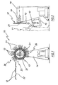
- Figure 1 is a schematic front elevation of a device to aid a person placing bags of snack foods in a box;
- Figure 2 is a schematic side elevation of the device of Figure 1;
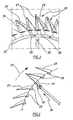
- Figure 3 is a schematic enlarged front elevation of a plurality of clips employed in the device of Figure 1; and
- Figure 4 is a schematic front elevation of portion of the clips of Figure 3.
-
- In the accompanying drawings, there is schematically depicted a
conveyor device 10 to aid aperson 11 to placebags 12 of snack foods in abox 13. Thedevice 10 includes a stand orbase 14 that rests on a floor surface so as to extend upwardly therefrom. Typically adjacent thebase 14, there would be provided a conveyor or supporting table 15, so thatboxes 13 may be positioned adjacent thedevice 10. - The
device 10 further includes ahub 17 rotatably mounted on thebase 14 for angular movement (rotation) about a generallyhorizontal axis 18. Also mounted in thebase 14 is a motor (preferably electric) 19 that rotates thehub 17. Typically, thedevice 10 would include switches (such as pedals) that are used by theperson 11 to control the delivery of electric energy to themotor 19 to thereby control thehub 17. Alternatively, themotor 19 may be electronically controlled. - Attached to the
hub 17 is a plurality ofclips 20 that engage thebags 12. Thebags 12 are delivered to thedevice 10 by means of aconveyor 22, with thebags 12 mounted thereon in a particular orientation, that is, with an end seal of the bag being positioned to enter a respective one of theclips 20. - Each
clip 20 includes afixed jaw 21 and amovable jaw 23 associated with each fixedjaw 21. Eachclip 20 has two configurations, that is, an open configuration ready to receive one of thebags 12, and a closed configuration securing one of thebags 12 to thehub 17. The open configuration of eachjaw 20 is a configuration in which thejaw 23 is spaced from thejaw 21. In the closed position, thejaw 23 is positioned in contact with or adjacent its respective fixedjaw 21 so that a portion of thebag 12 is located therebetween and secured to thehub 17. - Each
jaw 23 is pivotably mounted on thehub 17 by means of apin 24. Aspring 25 extending between eachjaw 23 and thehub 17 urging eachjaw 23 to pivot toward its respective fixedjaw 21. Accordingly, thejaws 23 are moved along a predetermined path and are moved from an open configuraton to a closed configuration at a predetermined location on said path. In the embodiment the path is circular. - At the predetermined
angular position 23, there is located acam mechanism 26. Thecam mechanism 26 includes a pivotably mountedarm 27 that engages aprojection 28 on eachjaw 23 to cause angular deflection of eachjaw 23 to the open position. When eachjaw 23 passes beyond thecam mechanism 26, thejaw member 23 is released so as to be urged into contact with abag 12 located between thejaw 21 and thejaw 23. Preferably, thearm 27 is pivotably mounted and is urged by a spring to the position depicted in Figure 4. As eachjaw 23 moves angularly in thedirection 29 when engaged with thearm 27, thearm 27 pivots to enable thejaw 23 to pass thereby. Aspring 30 urges thearm 27 to the position depicted in Figure 4. - The
motor 19 may be operated so that thebags 12 are located in spacedbatches 31. Thebatches 31 being spaced by one or moreempty clips 20. This would then enable theperson 11 to engage asingle batch 31 with each operation and place thebatch 31 in thebox 13. Accordingly, the speed of themotor 19 is varied. - The
hub 17 includes acentral shaft 31 from which there extends a plurality ofspokes 32 that are fixed to arim 33. Theclips 20 are mounted on therim 33 so as to be at the same radius relative to theaxis 18, and so as to be equally angularly spaced about theaxis 18. - In a further preferred form, each fixed
jaw 21 may be provided with aduct 34 to which a vacuum is delivered to aid in securing thebags 12 in position between thejaws jaws duct 34. Eachduct 34 would communicate with aduct 34 in therim 33, with theduct 34 in therim 33 communicating with a duct through one of thespokes 32 to be connected to a duct extending through theshaft 31 to an air pump. - Preferably, the
hub 17 would be positioned so that theperson 11 has thebags 12 arrive at approximately shoulder height to be gripped and placed in thebox 13. In this respect, it should be appreciated that theperson 11 may be seated or standing. - The
axis 18 is at an angle to the horizontal of between 0° and 20°, preferably about 10° so that thehub 17 andaxis 18 extends upwardly and away from theperson 11. - Accordingly, the
clips 20 are moved along a generally circular path having a lowermost segment 35 and anupper segment 36. At thesegment 35 theclips 20 are closed while at thesegment 36 the clips are open.
Claims (9)
- A bag conveyor device (10) to convey bags containing a product, said device including:a base (14);a clip assembly including a hub (17) rotatably mounted on the base for angular movement relative thereto about an axis (18), a plurality of clips (20) mounted on the hub so as to be moved thereby along a generally circular path having a lower most segment (35) and an upper segment (36), the clips being adapted to each receive a bag (12), each clip having an open configuration enabling a bag to be engaged therein and a closed configuration holding a bag located therein;a clip actuating mechanism (26) to operate the clips so that the clips move between the open configuration and the closed configuration at predetermined angular positions with respect to said axis so that said clips are in said closed configuration at said lower most segment and in said open configuration at said upper segment; anddrive means (19) to cause angular movement of said hub about said axis so that said bags are delivered to said lower most segment at which a person (11) can be positioned so that the person can engage the bags and remove the bags from the clips.
- The device of claim 1 wherein said axis (18) is substantially horizontal so that said hub is generally located in a generally vertical plane.
- The device of claim 1 wherein said axis is inclined by an acute angle to the horizontal so that the hub extends upwardly and away from the person.
- The device of claim 3 wherein said angle is between 5° and 20°.
- The device of claim 4 wherein said angle is about 10°.
- The device of claim 1 wherein each clip includes a first jaw (21), the first jaw being fixed with respect to said hub, and a second jaw (23) movably mounted on the hub so as to be movable with respect to the first jaw between the open and closed positions of the clip.
- The device of claim 6 wherein said hub (17) is positioned so that said lower most segment (35) is approximately shoulder height.
- The device of claim 7 wherein said second jaw (23) is resiliently urged towards said first jaw, and said actuating mechanism (26) is a cam member located adjacent said predetermined angular position so as to engage the second jaws to cause pivoting thereof to an open position to receive a bag, with said second jaw moving to the closed position of the clip upon passing said cam member.
- The device of claim 6 further including ducting extending to the fixed jaws so that a vacuum delivered thereto will urge the bags into contact with the fixed jaws.
Applications Claiming Priority (2)
| Application Number | Priority Date | Filing Date | Title |
|---|---|---|---|
| AUPS0614A AUPS061402A0 (en) | 2002-02-19 | 2002-02-19 | A device to aid packaging items |
| AUPS061402 | 2002-02-19 |
Publications (2)
| Publication Number | Publication Date |
|---|---|
| EP1336579A1 EP1336579A1 (en) | 2003-08-20 |
| EP1336579B1 true EP1336579B1 (en) | 2004-12-15 |
Family
ID=3834213
Family Applications (1)
| Application Number | Title | Priority Date | Filing Date |
|---|---|---|---|
| EP03250979A Expired - Lifetime EP1336579B1 (en) | 2002-02-19 | 2003-02-18 | A device to aid packaging items |
Country Status (7)
| Country | Link |
|---|---|
| US (1) | US7600630B2 (en) |
| EP (1) | EP1336579B1 (en) |
| JP (1) | JP2003246306A (en) |
| AT (1) | ATE284829T1 (en) |
| AU (2) | AUPS061402A0 (en) |
| BR (1) | BR0300388B1 (en) |
| DE (1) | DE60300200T2 (en) |
Families Citing this family (8)
| Publication number | Priority date | Publication date | Assignee | Title |
|---|---|---|---|---|
| EP2181948A1 (en) * | 2008-10-29 | 2010-05-05 | Wild Parma S.r.l. | Device for aligning pouches and similar |
| ITRM20120601A1 (en) | 2011-12-05 | 2013-06-06 | Tna Australia Pty Ltd | SHOULDER FORMER. |
| AU2012258403B2 (en) | 2011-12-05 | 2016-07-07 | Tna Australia Pty Limited | A former shoulder |
| ITRM20120599A1 (en) | 2011-12-05 | 2013-06-06 | Tna Australia Pty Ltd | DRAGGING GROUP OF THE FILM. |
| AU2014227559B2 (en) | 2013-11-19 | 2018-02-08 | Tna Australia Pty Limited | A film drive assembly for a packaging machine |
| AU2014227558B2 (en) * | 2013-11-19 | 2018-02-08 | Tna Australia Pty Limited | Sealing jaws for a packaging machine |
| MX2017010470A (en) | 2016-08-15 | 2018-09-19 | Tna Australia Pty Ltd | Packaging assembly. |
| KR101909266B1 (en) | 2017-05-30 | 2018-10-17 | (주)진성 테크템 | High speed-stacking machine for bundle packing |
Family Cites Families (32)
| Publication number | Priority date | Publication date | Assignee | Title |
|---|---|---|---|---|
| GB403711A (en) * | 1932-06-22 | 1933-12-22 | Frank Hugh Sowden | Improvements in or relating to sheet delivery apparatus for printing machines |
| NL296527A (en) | 1962-08-13 | |||
| US3232446A (en) | 1962-12-17 | 1966-02-01 | Monsanto Co | Article transfer mechanism |
| GB1316933A (en) | 1969-09-05 | 1973-05-16 | Molins Machine Co Ltd | Rotary conveyor article transfer apparatus |
| US3837474A (en) | 1971-11-12 | 1974-09-24 | Dalamere & Williams Co Ltd | Article handling apparatus |
| IT982254B (en) | 1973-03-05 | 1974-10-21 | Gd Spa | EQUIPMENT FOR THE OUTPUT OF PRODUCTS FROM A Wrapping and packaging line of said products, particularly packs of cigarettes and similar |
| US3868009A (en) | 1973-03-29 | 1975-02-25 | Carle & Montanari Spa | Transferring device |
| US3865631A (en) * | 1973-12-26 | 1975-02-11 | Charles S Naiman | Reserve batteries |
| US4283973A (en) | 1979-11-15 | 1981-08-18 | Paper Converting Machine Company | Method and apparatus for handling articles |
| GB2092090A (en) | 1981-01-29 | 1982-08-11 | Hulbritt Dev Ltd | Packing apparatus |
| DE3404459A1 (en) * | 1984-02-08 | 1985-08-14 | Frankenthal Ag Albert | METHOD AND DEVICE FOR DISPLAYING ARC-SHAPED PRODUCTS IN THE FORM OF A SHED FLOW |
| DE3605534A1 (en) * | 1986-02-20 | 1987-08-27 | Rotaprint Gmbh | BOW CONVEYOR FOR BOW PROCESSING MACHINES |
| IT1201607B (en) | 1986-12-17 | 1989-02-02 | Gd Spa | METHOD FOR TRANSFER AND ORDERING ACCORDING TO A DETERMINED STEP OF PRODUCTS FEEDING WITH A RANDOM ORDER |
| DD264660A1 (en) | 1987-10-29 | 1989-02-08 | Nagema Veb K | SWEET TRANSFER DEVICE |
| FR2672031B1 (en) | 1991-01-29 | 1994-10-21 | Cazas Ets | CASE MACHINE FOR UNIT DOSING. |
| DE4105388C2 (en) | 1991-02-21 | 1994-04-28 | Werner Bonnet | Device for gripping and transporting objects |
| DE4223555A1 (en) * | 1991-08-12 | 1993-02-18 | Koenig & Bauer Ag | DRUM FOR TRANSPORTING BOWS |
| EP0541835B1 (en) | 1991-11-11 | 1995-02-01 | PACTEC DRESDEN GmbH | Device for conveying sweets |
| DE4219631C2 (en) | 1992-06-16 | 1994-04-07 | Pactec Dresden Gmbh | Device for the continuous acceptance of the candies separated from a massage strand fed at a constant speed |
| DK0606550T3 (en) * | 1993-01-14 | 1997-10-06 | Ferag Ag | Device for conveying flat products to a printing device processing device |
| US5452886A (en) * | 1993-08-09 | 1995-09-26 | Heidelberger Druckmaschinen Ag | Device for slowing down signatures in a folding machine |
| IT1279673B1 (en) | 1995-11-07 | 1997-12-16 | Acma Spa | EQUIPMENT AND METHOD FOR THE FORMATION OF ORDERED GROUPS OF PRODUCTS TO BE FOOD BY STEP. |
| DE19616989C1 (en) * | 1996-04-27 | 1997-10-02 | Bosch Gmbh Robert | Device for separating and picking up sweets |
| IT1294073B1 (en) | 1997-02-19 | 1999-03-22 | Chronos Richardson S A | DEVICE TO TRANSFER BAGS FROM A FILLING STATION TO A CONVEYOR. |
| DE19752680A1 (en) * | 1997-11-28 | 1999-06-02 | Heidelberger Druckmasch Ag | Method and device for transferring the trailing edge of a sheet in a turning device of a sheet-fed rotary printing press |
| AUPP093997A0 (en) | 1997-12-12 | 1998-01-08 | Tna Australia Pty Limited | A conveyor |
| DE19822306A1 (en) * | 1998-05-18 | 1999-11-25 | Heidelberger Druckmasch Ag | Suction pad in a turning device of a sheet-fed rotary printing press |
| EP0967164B1 (en) * | 1998-06-22 | 2001-10-31 | Grapha-Holding Ag | Method and device for feeding folded printed sheets astride on a gathering section |
| IT1304033B1 (en) * | 1998-07-14 | 2001-03-02 | Gd Spa | PACKAGING MACHINE. |
| US6227589B1 (en) * | 1999-12-01 | 2001-05-08 | Philadelphia Newspapers, Inc. | Gripper assembly for a conveying device for conveying single-sheet or multi-sheet printed products and a method for modifying the same |
| US6612563B1 (en) * | 2000-03-31 | 2003-09-02 | Graphic Management Associates, Inc. | Stacking and counting device for planar products |
| ATE258533T1 (en) * | 2000-10-02 | 2004-02-15 | Ferag Ag | METHOD AND DEVICE FOR FORMING A DOUBLE SHADE FORMATION FROM PRINTED PRODUCTS |
-
2002
- 2002-02-19 AU AUPS0614A patent/AUPS061402A0/en not_active Abandoned
-
2003
- 2003-02-12 AU AU2003200456A patent/AU2003200456B9/en not_active Ceased
- 2003-02-18 DE DE60300200T patent/DE60300200T2/en not_active Expired - Lifetime
- 2003-02-18 AT AT03250979T patent/ATE284829T1/en not_active IP Right Cessation
- 2003-02-18 EP EP03250979A patent/EP1336579B1/en not_active Expired - Lifetime
- 2003-02-19 JP JP2003041236A patent/JP2003246306A/en active Pending
- 2003-02-19 US US10/371,164 patent/US7600630B2/en not_active Expired - Fee Related
- 2003-02-19 BR BRPI0300388-4A patent/BR0300388B1/en not_active IP Right Cessation
Also Published As
| Publication number | Publication date |
|---|---|
| US7600630B2 (en) | 2009-10-13 |
| DE60300200D1 (en) | 2005-01-20 |
| BR0300388B1 (en) | 2014-07-22 |
| EP1336579A1 (en) | 2003-08-20 |
| JP2003246306A (en) | 2003-09-02 |
| ATE284829T1 (en) | 2005-01-15 |
| AU2003200456A1 (en) | 2003-09-04 |
| AU2003200456B9 (en) | 2008-11-20 |
| US20040003983A1 (en) | 2004-01-08 |
| BR0300388A (en) | 2004-08-17 |
| DE60300200T2 (en) | 2006-03-02 |
| AU2003200456B2 (en) | 2008-06-19 |
| AUPS061402A0 (en) | 2002-03-14 |
Similar Documents
| Publication | Publication Date | Title |
|---|---|---|
| JP4454968B2 (en) | Product packing method and machine using flat cylindrical parcel | |
| US7364029B2 (en) | Apparatus for simultaneously conveying and rotating objects | |
| EP1336579B1 (en) | A device to aid packaging items | |
| JP4667633B2 (en) | Empty bag supply device and product bag take-out device in continuous transfer type bag filling and packaging machine | |
| US11203455B2 (en) | Wrapping machine printer arrangement and wrapping machine film cutter arrangement | |
| JP2022169338A (en) | bag processing machine | |
| CN115402593A (en) | Bag feeding and packaging method | |
| US6263645B1 (en) | Vertical bagger | |
| WO2002072430A1 (en) | Bag take-out device, and suction port construction in bag or sheet suction take-out means | |
| JP4992007B2 (en) | Device for feeding carton blanks to packaging machines | |
| US6922977B2 (en) | Ergonomic blister packaging machine | |
| JP2011073777A (en) | Bag discharge auxiliary device in bagging and packaging machine | |
| JPH09249201A (en) | Carton cover closing equipment | |
| JP4666603B2 (en) | Bag feeder | |
| JP2003137219A (en) | Conveyer-magazine-type bag feeder | |
| JPH07241939A (en) | Folding case opening method and opening device | |
| JP4184214B2 (en) | Gazette bag / flat bag packaging machine | |
| KR101905373B1 (en) | Packing pouch transfer | |
| MX2013010028A (en) | Transfer system for setting a piece in a required orientation, and robot gripper for said transfer system. | |
| JP3568519B2 (en) | Packaging machine bag feeding device | |
| JPH10194238A (en) | Method for supplying of packaging bag and device thereof | |
| JPH092422A (en) | Packing device | |
| JPS63281903A (en) | Bagging apparatus | |
| JP2710643B2 (en) | Sealing machine | |
| CN112298679A (en) | Automatic packaging equipment and automatic packaging method |
Legal Events
| Date | Code | Title | Description |
|---|---|---|---|
| PUAI | Public reference made under article 153(3) epc to a published international application that has entered the european phase |
Free format text: ORIGINAL CODE: 0009012 |
|
| AK | Designated contracting states |
Designated state(s): AT BE BG CH CY CZ DE DK EE ES FI FR GB GR HU IE IT LI LU MC NL PT SE SI SK TR |
|
| AX | Request for extension of the european patent |
Extension state: AL LT LV MK RO |
|
| 17P | Request for examination filed |
Effective date: 20030901 |
|
| 17Q | First examination report despatched |
Effective date: 20031027 |
|
| AKX | Designation fees paid |
Designated state(s): AT BE BG CH CY CZ DE DK EE ES FI FR GB GR HU IE IT LI LU MC NL PT SE SI SK TR |
|
| GRAP | Despatch of communication of intention to grant a patent |
Free format text: ORIGINAL CODE: EPIDOSNIGR1 |
|
| GRAS | Grant fee paid |
Free format text: ORIGINAL CODE: EPIDOSNIGR3 |
|
| GRAA | (expected) grant |
Free format text: ORIGINAL CODE: 0009210 |
|
| AK | Designated contracting states |
Kind code of ref document: B1 Designated state(s): AT BE BG CH CY CZ DE DK EE ES FI FR GB GR HU IE IT LI LU MC NL PT SE SI SK TR |
|
| PG25 | Lapsed in a contracting state [announced via postgrant information from national office to epo] |
Ref country code: IT Free format text: LAPSE BECAUSE OF FAILURE TO SUBMIT A TRANSLATION OF THE DESCRIPTION OR TO PAY THE FEE WITHIN THE PRESCRIBED TIME-LIMIT;WARNING: LAPSES OF ITALIAN PATENTS WITH EFFECTIVE DATE BEFORE 2007 MAY HAVE OCCURRED AT ANY TIME BEFORE 2007. THE CORRECT EFFECTIVE DATE MAY BE DIFFERENT FROM THE ONE RECORDED. Effective date: 20041215 Ref country code: BG Free format text: LAPSE BECAUSE OF FAILURE TO SUBMIT A TRANSLATION OF THE DESCRIPTION OR TO PAY THE FEE WITHIN THE PRESCRIBED TIME-LIMIT Effective date: 20041215 Ref country code: LI Free format text: LAPSE BECAUSE OF FAILURE TO SUBMIT A TRANSLATION OF THE DESCRIPTION OR TO PAY THE FEE WITHIN THE PRESCRIBED TIME-LIMIT Effective date: 20041215 Ref country code: CZ Free format text: LAPSE BECAUSE OF FAILURE TO SUBMIT A TRANSLATION OF THE DESCRIPTION OR TO PAY THE FEE WITHIN THE PRESCRIBED TIME-LIMIT Effective date: 20041215 Ref country code: FI Free format text: LAPSE BECAUSE OF FAILURE TO SUBMIT A TRANSLATION OF THE DESCRIPTION OR TO PAY THE FEE WITHIN THE PRESCRIBED TIME-LIMIT Effective date: 20041215 Ref country code: EE Free format text: LAPSE BECAUSE OF FAILURE TO SUBMIT A TRANSLATION OF THE DESCRIPTION OR TO PAY THE FEE WITHIN THE PRESCRIBED TIME-LIMIT Effective date: 20041215 Ref country code: SI Free format text: LAPSE BECAUSE OF FAILURE TO SUBMIT A TRANSLATION OF THE DESCRIPTION OR TO PAY THE FEE WITHIN THE PRESCRIBED TIME-LIMIT Effective date: 20041215 Ref country code: CH Free format text: LAPSE BECAUSE OF FAILURE TO SUBMIT A TRANSLATION OF THE DESCRIPTION OR TO PAY THE FEE WITHIN THE PRESCRIBED TIME-LIMIT Effective date: 20041215 Ref country code: AT Free format text: LAPSE BECAUSE OF FAILURE TO SUBMIT A TRANSLATION OF THE DESCRIPTION OR TO PAY THE FEE WITHIN THE PRESCRIBED TIME-LIMIT Effective date: 20041215 Ref country code: TR Free format text: LAPSE BECAUSE OF FAILURE TO SUBMIT A TRANSLATION OF THE DESCRIPTION OR TO PAY THE FEE WITHIN THE PRESCRIBED TIME-LIMIT Effective date: 20041215 Ref country code: BE Free format text: LAPSE BECAUSE OF FAILURE TO SUBMIT A TRANSLATION OF THE DESCRIPTION OR TO PAY THE FEE WITHIN THE PRESCRIBED TIME-LIMIT Effective date: 20041215 Ref country code: FR Free format text: LAPSE BECAUSE OF FAILURE TO SUBMIT A TRANSLATION OF THE DESCRIPTION OR TO PAY THE FEE WITHIN THE PRESCRIBED TIME-LIMIT Effective date: 20041215 Ref country code: SK Free format text: LAPSE BECAUSE OF FAILURE TO SUBMIT A TRANSLATION OF THE DESCRIPTION OR TO PAY THE FEE WITHIN THE PRESCRIBED TIME-LIMIT Effective date: 20041215 |
|
| REG | Reference to a national code |
Ref country code: CH Ref legal event code: EP Ref country code: GB Ref legal event code: FG4D |
|
| REG | Reference to a national code |
Ref country code: IE Ref legal event code: FG4D |
|
| REF | Corresponds to: |
Ref document number: 60300200 Country of ref document: DE Date of ref document: 20050120 Kind code of ref document: P |
|
| PG25 | Lapsed in a contracting state [announced via postgrant information from national office to epo] |
Ref country code: IE Free format text: LAPSE BECAUSE OF NON-PAYMENT OF DUE FEES Effective date: 20050218 Ref country code: LU Free format text: LAPSE BECAUSE OF NON-PAYMENT OF DUE FEES Effective date: 20050218 Ref country code: CY Free format text: LAPSE BECAUSE OF FAILURE TO SUBMIT A TRANSLATION OF THE DESCRIPTION OR TO PAY THE FEE WITHIN THE PRESCRIBED TIME-LIMIT Effective date: 20050218 |
|
| PG25 | Lapsed in a contracting state [announced via postgrant information from national office to epo] |
Ref country code: MC Free format text: LAPSE BECAUSE OF NON-PAYMENT OF DUE FEES Effective date: 20050228 |
|
| PG25 | Lapsed in a contracting state [announced via postgrant information from national office to epo] |
Ref country code: DK Free format text: LAPSE BECAUSE OF FAILURE TO SUBMIT A TRANSLATION OF THE DESCRIPTION OR TO PAY THE FEE WITHIN THE PRESCRIBED TIME-LIMIT Effective date: 20050315 Ref country code: SE Free format text: LAPSE BECAUSE OF FAILURE TO SUBMIT A TRANSLATION OF THE DESCRIPTION OR TO PAY THE FEE WITHIN THE PRESCRIBED TIME-LIMIT Effective date: 20050315 |
|
| PG25 | Lapsed in a contracting state [announced via postgrant information from national office to epo] |
Ref country code: HU Free format text: LAPSE BECAUSE OF FAILURE TO SUBMIT A TRANSLATION OF THE DESCRIPTION OR TO PAY THE FEE WITHIN THE PRESCRIBED TIME-LIMIT Effective date: 20050316 |
|
| PG25 | Lapsed in a contracting state [announced via postgrant information from national office to epo] |
Ref country code: ES Free format text: LAPSE BECAUSE OF FAILURE TO SUBMIT A TRANSLATION OF THE DESCRIPTION OR TO PAY THE FEE WITHIN THE PRESCRIBED TIME-LIMIT Effective date: 20050326 |
|
| REG | Reference to a national code |
Ref country code: GR Ref legal event code: EP Ref document number: 20050400698 Country of ref document: GR |
|
| REG | Reference to a national code |
Ref country code: CH Ref legal event code: PL |
|
| PLBE | No opposition filed within time limit |
Free format text: ORIGINAL CODE: 0009261 |
|
| STAA | Information on the status of an ep patent application or granted ep patent |
Free format text: STATUS: NO OPPOSITION FILED WITHIN TIME LIMIT |
|
| REG | Reference to a national code |
Ref country code: IE Ref legal event code: MM4A |
|
| 26N | No opposition filed |
Effective date: 20050916 |
|
| EN | Fr: translation not filed | ||
| PG25 | Lapsed in a contracting state [announced via postgrant information from national office to epo] |
Ref country code: PT Free format text: LAPSE BECAUSE OF NON-PAYMENT OF DUE FEES Effective date: 20050515 |
|
| PGFP | Annual fee paid to national office [announced via postgrant information from national office to epo] |
Ref country code: NL Payment date: 20140208 Year of fee payment: 12 |
|
| PGFP | Annual fee paid to national office [announced via postgrant information from national office to epo] |
Ref country code: GR Payment date: 20140214 Year of fee payment: 12 |
|
| PGFP | Annual fee paid to national office [announced via postgrant information from national office to epo] |
Ref country code: GB Payment date: 20140212 Year of fee payment: 12 |
|
| PGFP | Annual fee paid to national office [announced via postgrant information from national office to epo] |
Ref country code: DE Payment date: 20140417 Year of fee payment: 12 |
|
| REG | Reference to a national code |
Ref country code: DE Ref legal event code: R119 Ref document number: 60300200 Country of ref document: DE |
|
| REG | Reference to a national code |
Ref country code: NL Ref legal event code: V1 Effective date: 20150901 |
|
| PG25 | Lapsed in a contracting state [announced via postgrant information from national office to epo] |
Ref country code: NL Free format text: LAPSE BECAUSE OF NON-PAYMENT OF DUE FEES Effective date: 20150901 |
|
| GBPC | Gb: european patent ceased through non-payment of renewal fee |
Effective date: 20150218 |
|
| REG | Reference to a national code |
Ref country code: GR Ref legal event code: ML Ref document number: 20050400698 Country of ref document: GR Effective date: 20150902 |
|
| PG25 | Lapsed in a contracting state [announced via postgrant information from national office to epo] |
Ref country code: GR Free format text: LAPSE BECAUSE OF NON-PAYMENT OF DUE FEES Effective date: 20150902 |
|
| PG25 | Lapsed in a contracting state [announced via postgrant information from national office to epo] |
Ref country code: DE Free format text: LAPSE BECAUSE OF NON-PAYMENT OF DUE FEES Effective date: 20150901 Ref country code: GB Free format text: LAPSE BECAUSE OF NON-PAYMENT OF DUE FEES Effective date: 20150218 |