EP1335552B1 - Estimation of channel response and of delay in multicarrier systems - Google Patents
Estimation of channel response and of delay in multicarrier systems Download PDFInfo
- Publication number
- EP1335552B1 EP1335552B1 EP02250843A EP02250843A EP1335552B1 EP 1335552 B1 EP1335552 B1 EP 1335552B1 EP 02250843 A EP02250843 A EP 02250843A EP 02250843 A EP02250843 A EP 02250843A EP 1335552 B1 EP1335552 B1 EP 1335552B1
- Authority
- EP
- European Patent Office
- Prior art keywords
- sub
- carriers
- values
- distortion
- channel
- Prior art date
- Legal status (The legal status is an assumption and is not a legal conclusion. Google has not performed a legal analysis and makes no representation as to the accuracy of the status listed.)
- Expired - Lifetime
Links
Images


Classifications
-
- H—ELECTRICITY
- H04—ELECTRIC COMMUNICATION TECHNIQUE
- H04L—TRANSMISSION OF DIGITAL INFORMATION, e.g. TELEGRAPHIC COMMUNICATION
- H04L27/00—Modulated-carrier systems
- H04L27/26—Systems using multi-frequency codes
- H04L27/2601—Multicarrier modulation systems
- H04L27/2647—Arrangements specific to the receiver only
-
- H—ELECTRICITY
- H04—ELECTRIC COMMUNICATION TECHNIQUE
- H04L—TRANSMISSION OF DIGITAL INFORMATION, e.g. TELEGRAPHIC COMMUNICATION
- H04L25/00—Baseband systems
- H04L25/02—Details ; arrangements for supplying electrical power along data transmission lines
- H04L25/0202—Channel estimation
- H04L25/0224—Channel estimation using sounding signals
- H04L25/0228—Channel estimation using sounding signals with direct estimation from sounding signals
- H04L25/023—Channel estimation using sounding signals with direct estimation from sounding signals with extension to other symbols
- H04L25/0232—Channel estimation using sounding signals with direct estimation from sounding signals with extension to other symbols by interpolation between sounding signals
- H04L25/0234—Channel estimation using sounding signals with direct estimation from sounding signals with extension to other symbols by interpolation between sounding signals by non-linear interpolation
Definitions
- the invention relates to multicarrier systems, for example Orthogonal Frequency Division Multiplex (OFDM) receivers.
- the invention relates to estimating the channel transfer function of a transmission, for example to enable correction for the distortions which can occur between a transmitter output and a receiver input, especially due to multipath interference in radio transmission.
- OFDM Orthogonal Frequency Division Multiplex
- each individual modulation symbol on each sub-carrier has a long duration.
- channel impairments caused by a particular receiver receiving reflected signals so-called multipath distortion and channel delay spread, are greatly reduced. This occurs since data on delayed signals from reflected paths hardly overlap with previously transmitted data on the direct path, as the duration of the data symbols on each sub-carrier is much longer than the delay spread caused by reflections.
- a channel estimator calculates this effect and allows the distortion to be compensated.
- Coherent modulation employs absolute values of amplitude and phase to convey the data. This makes the signal much more susceptible to channel impairments. For this reason, when employing coherently modulated OFDM, 'pilot' sub-carriers, with modulation values known by the receiver, are normally transmitted along with the main signal. The received pilots are then compared with what they should be and the difference is used to estimate and remove the channel distortion. This procedure is called equalisation.
- DVB-T digital video broadcasting terrestrial
- ISDB-T Integrated Service Digital Broadcasting Terrestrial
- WLANs wireless local area networks
- DVB-T and WLANs the pilots are only transmitted on certain sub-carriers at certain times.
- pilot sub-carriers may be transmitted on each OFDM symbol, but only on a few of the sub-carriers.
- US 2001/015954 A1 discloses an OFDM receiver in which data signals and pilot signals are extracted.
- a complex dividing unit divides the extracted pilot signal by values corresponding with the transmitted pilot signal.
- the results for several pilot signals are interpolated in order to calculate transmission path estimation values used to correct the extracted data signal.
- WO 01/56239 A describes an OFDM receiver in which signals indicative of distortion in pilot signals are analysed in order to compute correction factors which are applied to received signals. Separate correction factors may be computed for each frequency using interpolation.
- the receiver includes means for calculating the rate at which phase errors in pilots change with time.
- characteristics of the channel over which the signal has passed are identified by using the transmitted sub-carriers, particularly the pilots, in a novel way.
- the identification is done by evaluation of the characteristic change in phase introduced by the channel between distortion values of adjacent pilot sub-carriers.
- the channel distortion can then be compensated by equalising the channel response.
- This system generally produces superior results to prior art interpolation or filtering which technique becomes progressively worse as the multipath delay spread becomes a larger fraction of the OFDM symbol length. This is because the ripples in the signal spectrum caused by the multipath channel become more closely spaced relative to the pilot spacing. The filtered or interpolated estimation then becomes less exact.
- the invention could be applied to multicarrier systems which do not use pilots, provided the signal constellation of the transmitted data is known, for example in binary phase-shift keying and quadrature phase-shift keying systems.
- a data-aided decision procedure could be used wherein, for at least some sub-carriers, the derived complex data value is used to select one of a set of predetermined possible data values, the closest one being selected.
- a data distortion value can then be determined by comparing the derived complex value with the selected predetermined value. This permits the determination of distortion estimates for other sub-carriers. Accordingly, assuming that the data carried by some sub-carriers can be determined, it is possible to compensate for noise which may make the determination of the values carried by other sub-carriers difficult.
- the invention will primarily be described in relation to estimated channel transfer functions for the purpose of channel equalisation, it is possible alternatively or additionally to use the techniques for measurement of the delay between two versions of a multicarrier signal. This is because the phase change between distortion values of different sub-carriers is dependent upon this time delay and therefore by determining the rate at which the phase changes, the time delay can be calculated. Accordingly, the invention could be applied to range finding or object-detection systems in which the time delay represents the distance between two points, one of which is the location of an object reflecting the signal, and the other of which is the location of another reflecting object or the source of the multicarrier signal (which may also be the location of the receiver of the signal).
- An OFDM receiver 2 is shown in Figure 1.
- An OFDM signal which may have been subjected to multi-path reflection, is received at an antenna 4 and down converted to a suitable intermediate frequency (IF) by a down-converter 6.
- the signal is then sampled and converted to in-phase and quadrature components (complex numbers) by an IF-to-baseband converter 8 using methods which are in themselves well known.
- This sampled time domain signal is then transformed to the frequency domain by the receiver's Fast Fourier Transform (FFT) signal-processing block 10.
- FFT Fast Fourier Transform
- the outputs of the FFT block are the received OFDM sub-carriers free of inter-carrier-interference (ICI).
- ICI inter-carrier-interference
- the equalised data sub-carriers are then delivered to a demodulation and data decoding block 18.
- the technique described so far is known in the prior art.
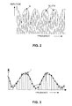
- this shows a typical plot of the amplitudes of pilot sub-carriers at different frequencies within a signal subject to multi-path interference which causes rapid variations, with respect to frequency, of the channel response characteristic R.
- Prior art techniques attempt to determine the response characteristic R by interpolation between adjacent pairs of pilot sub-carriers.
- a pilot distortion value is calculated, for example by taking the ratio of the received signal to the known modulation values, to obtain a value P n for the channel transfer function of the sub-carrier n.
- a two-path system will produce a linear change in this phase, i.e. ⁇ is a constant.
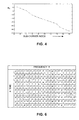
- the phase when plotted against frequency, shows a varying degree of ripple along a dominant trend of a straight line, reflecting the aggregate effects from all the paths, as indicated in Figure 4.
- the variation of the phase ⁇ n with respect to frequency is calculated, for example by assuming a straight line and determining the slope ⁇ of the line, this describing an equivalent two-path model that approximates the phase characteristic of the actual sampled channel response.
- n the sub-carrier index
- N the number of pilots used
- k the pilot spacing
- n 0 the carrier position of the lowest frequency pilot
- Equation (8) can be shown to be valid for i ⁇ 0 and 0 ⁇ i ⁇ k .
- Equations (8) and (9) are globally valid only for precise two-paths channels. For other more generic multi-paths scenarios, they should be regarded as a local small signal approximation to the channel gains expressed as an equivalent two paths model centred at the pivotal point.
- Figure 5 is a block diagram of a channel estimation and equalisation block 16 which operates using these techniques.
- the OFDM sub-carriers are fed from block input 50 to a sorting component 51 which separates the pilots from the data sub-carriers, based on the control output from a pilot selector 52, which indicates which sub-carriers are pilots.
- the pilots are then fed to a divider 53, where the channel response samples at the pilot positions are evaluated, by comparison with the known modulated data (obtained from pilot data source 54) on these pilot sub-carriers.
- the output from divider 53 is a serial string of the channel response samples. These samples are regrouped, in general at the boundary of a symbol, to form framed data for filtering operations in time within a filter 55.
- phase calculator 58 The output of subtractor 57 is fed to a phase calculator 58.
- the phase value ⁇ n of the value ⁇ P n is calculated using an inverse trigonometric function.
- An array of phase values is then grouped for phase unwrapping in a phase unwrapper 59.
- this procedure can be refined to avoid potential errors due to noise.
- the number of times 2 ⁇ is subtracted from ⁇ n can be controlled to ensure a uniform trend in the amount by which the unwrapped values ⁇ n change.
- the mean value of all ⁇ n - ⁇ n-k , ⁇ n , out of the unwrapped array [..., ⁇ n-k , ⁇ n , ⁇ n+k , ...] can be calculated, and then in a second stage the mean value ⁇ n is used as guidance in deciding whether the last 2 ⁇ adjustment (unwrapping) of ⁇ n should be avoided.
- the idea is to compare which value, i.e.
- ⁇ n or ⁇ n +2 ⁇ is closer to the predicted straight line trend point of ⁇ n as indicated by ⁇ n-k + ⁇ n , and use the closer value one for ⁇ n (the net effect is maintaining or cancelling the last 2 ⁇ adjustment on ⁇ n ). This however leads to a degree of increased complexity and some extra time delay in pipeline implementations.
- the unwrapped phase array is then forwarded to an evaluation component 60 where the parameter ⁇ , i.e. the rotation variable, is evaluated in accordance with equation (1).
- the result is fed to an interpolator 61 for calculating the set of data sub-carrier channel response interpolation gains, which for each data sub-carrier would be: ( 1 - e j ⁇ i / k ) / 1 - e j ⁇ or ( 1 - e j ⁇ i / k ) / 1 - e - j ⁇ ⁇ .
- k 3 and all the data sub-carriers are located between two pilots, there would be k -1 (i.e. 2) complex gains in the gain sets, corresponding to each of the two data sub-carrier positions respectively.
- the gain elements in the set are then successively fed to a complex multiplier 62 which multiples by ⁇ P n received from subtractor 57.
- the output is fed to a summer 63 which also receives P n from filter 55, thus outputting interpolations of the channel response at the data sub-carrier positions, as described by equations (8) and (9).
- equation (8) is used where n is the closest pilot, and equation (9) where n+k is the closest pilot, at least for data sub-carrier positions near the edges of the signal spectrum, i.e. where the carriers are not between a pair of pilots; for other data sub-carriers either of equations (8) and (9) could be used.
- the output from summer 63 is fed to a complex divider 64.
- the other input to divider 64 is the FFT result of each received data sub-carrier in a serial stream, the division of this stream by its corresponding channel response resulting in a stream of equalised data sub-carriers, with the channel distortion removed or alleviated.
- These equalised data sub-carriers appear at the output 66 of the channel equalisation block and are ready to be demodulated to recover the transmitted data in the demodulation and data decoding block.
- the threshold may be the value that leads to the magnitude of (1 - e -j ⁇ ) having only one least significant bit (LSB) which is non-zero in amplitude. This situation would occur, for example, when the channel consists of a single ray (i.e. a flat channel response with no multi-path interference).
- the filtering in time performed by filter 55 is particularly important where to improve accuracy interpolation is based on pilot carriers distributed over a plurality of symbols, possibly with the pilots in different symbols located at different sub-carriers (which would require the pilot selector 52 to operate differently from symbol to symbol), and/or possibly by combining a plurality of pilots at the same sub-carriers in respective symbols.
- pilots are transmitted every 12 th sub-carrier in a rotating fashion as shown in Figure 6, a system called "scattered pilots".
- the signal spectrum is split up into 13 segments, not all of which may contain coherent modulation.
- the pilots sub-carriers are defined as scattered pilots as for DVB-T.
- filtering can be achieved by linear interpolation among a group of consecutive symbols in which pilots are repeated at the same sub-carrier locations. In the cases of DVB-T and ISDB-T, this would require filtering over seven symbols, though a performance benefit can be achieved.
- time delay spread 1 / k ⁇ ⁇ ⁇ f OFDM
- the OFDM carrier spectrum is partitioned into a number of sections and interpolation is performed separately in each of the sections.
- Section based modelling has some inherent advantages in segment based OFDM transmission schemes, such as the ISDB-T.
- Another alternative implementation involves filtering the rotational angle variable ⁇ in time and using the filter output to guide the phase angle unwrapping operation. It is also possible, in a section-partition based implementation, for the ⁇ value from a previous section to be used to guide the current section's phase unwrapping operations. These alternatives can lead to reduction of pipelining complexity and throughput latency.
- all the sub-carriers may be pilots carrying known data values, and equalisation (and consequently interpolation) may not be required.
Landscapes
- Engineering & Computer Science (AREA)
- Computer Networks & Wireless Communication (AREA)
- Signal Processing (AREA)
- Physics & Mathematics (AREA)
- Nonlinear Science (AREA)
- Power Engineering (AREA)
- Noise Elimination (AREA)
- Cable Transmission Systems, Equalization Of Radio And Reduction Of Echo (AREA)
- Radio Transmission System (AREA)
Description
- The invention relates to multicarrier systems, for example Orthogonal Frequency Division Multiplex (OFDM) receivers. In particular, the invention relates to estimating the channel transfer function of a transmission, for example to enable correction for the distortions which can occur between a transmitter output and a receiver input, especially due to multipath interference in radio transmission.
- Using OFDM, each individual modulation symbol on each sub-carrier has a long duration. In this way channel impairments caused by a particular receiver receiving reflected signals, so-called multipath distortion and channel delay spread, are greatly reduced. This occurs since data on delayed signals from reflected paths hardly overlap with previously transmitted data on the direct path, as the duration of the data symbols on each sub-carrier is much longer than the delay spread caused by reflections. However, if reflected signals are present, the frequency response of the channel is affected, and individual sub-carriers within the OFDM signal may be attenuated. A channel estimator calculates this effect and allows the distortion to be compensated.
- To increase the data rate, coherent modulation is often employed. Coherent modulation employs absolute values of amplitude and phase to convey the data. This makes the signal much more susceptible to channel impairments. For this reason, when employing coherently modulated OFDM, 'pilot' sub-carriers, with modulation values known by the receiver, are normally transmitted along with the main signal. The received pilots are then compared with what they should be and the difference is used to estimate and remove the channel distortion. This procedure is called equalisation.
- Current wireless transmission schemes, for example digital video broadcasting terrestrial (DVB-T), Integrated Service Digital Broadcasting Terrestrial (ISDB-T), wireless local area networks, WLANs, (HIPERLAN/2, IEEE802.11a, MMAC) and digital audio broadcasting (DAB) all make use of pilot sub-carriers to help overcome the effect of multi-path signals. In the cases of DVB-T, ISDB-T and wireless LANs the pilots are only transmitted on certain sub-carriers at certain times. For DVB-T and ISDB-T pilot sub-carriers may be transmitted on each OFDM symbol, but only on a few of the sub-carriers.
- In order to be able to correct for the signal distortions caused by the channel on the data sub-carriers between the known pilots, current receivers use filters and/or linear interpolators to interpolate between the pilots, and use the interpolated results to correct for the channel. Often several pilots are used with filtering in the frequency direction and in the time direction to remove the effects of noise. However, if the variations in the channel in the sub-carrier direction (i.e. in the frequency direction) are rapid, as will occur if reflected secondary signals are delayed for a relative long period with respect to the symbol duration of the main path OFDM signal, it is difficult to interpolate correctly. Additionally, it is difficult for the filter based channel equalisation approach to deal with the sub-carriers at the edge of the signal spectrum. At the low frequency edge there are no pilots which can be used below the edge of the spectrum; similarly at the high frequency edge there are no pilot sub-carriers higher in frequency. This increases the complexity of the filter implementation.
- US 2001/015954 A1 discloses an OFDM receiver in which data signals and pilot signals are extracted. A complex dividing unit divides the extracted pilot signal by values corresponding with the transmitted pilot signal. The results for several pilot signals are interpolated in order to calculate transmission path estimation values used to correct the extracted data signal.
- WO 01/56239 A describes an OFDM receiver in which signals indicative of distortion in pilot signals are analysed in order to compute correction factors which are applied to received signals. Separate correction factors may be computed for each frequency using interpolation. For the purposes of synchronisation, the receiver includes means for calculating the rate at which phase errors in pilots change with time.
- It would be desirable to provide an improved signal-processing method for channel estimation.
- Aspects of the present invention are set out in the accompanying claims.
- In the preferred embodiment described below, characteristics of the channel over which the signal has passed are identified by using the transmitted sub-carriers, particularly the pilots, in a novel way. The identification is done by evaluation of the characteristic change in phase introduced by the channel between distortion values of adjacent pilot sub-carriers.
- The channel distortion can then be compensated by equalising the channel response. This system generally produces superior results to prior art interpolation or filtering which technique becomes progressively worse as the multipath delay spread becomes a larger fraction of the OFDM symbol length. This is because the ripples in the signal spectrum caused by the multipath channel become more closely spaced relative to the pilot spacing. The filtered or interpolated estimation then becomes less exact.
- Various alternative possibilities are envisaged.
- For example, the invention could be applied to multicarrier systems which do not use pilots, provided the signal constellation of the transmitted data is known, for example in binary phase-shift keying and quadrature phase-shift keying systems. Thus, a data-aided decision procedure could be used wherein, for at least some sub-carriers, the derived complex data value is used to select one of a set of predetermined possible data values, the closest one being selected. A data distortion value can then be determined by comparing the derived complex value with the selected predetermined value. This permits the determination of distortion estimates for other sub-carriers. Accordingly, assuming that the data carried by some sub-carriers can be determined, it is possible to compensate for noise which may make the determination of the values carried by other sub-carriers difficult.
- Although the invention will primarily be described in relation to estimated channel transfer functions for the purpose of channel equalisation, it is possible alternatively or additionally to use the techniques for measurement of the delay between two versions of a multicarrier signal. This is because the phase change between distortion values of different sub-carriers is dependent upon this time delay and therefore by determining the rate at which the phase changes, the time delay can be calculated. Accordingly, the invention could be applied to range finding or object-detection systems in which the time delay represents the distance between two points, one of which is the location of an object reflecting the signal, and the other of which is the location of another reflecting object or the source of the multicarrier signal (which may also be the location of the receiver of the signal).
- An arrangement embodying the invention will now be described by way of example with reference to the accompanying drawings, in which:
- Figure 1 is a block diagram of an OFDM receiver to which the techniques of the present invention can be applied;
- Figure 2 shows the spectrum of the pilot sub-carriers of a signal resulting from a two path channel;
- Figure 3 is a diagram to show interpolation errors resulting from a prior art linear interpolation technique;
- Figure 4 shows a typical trend of the phase of a value representing changes in the distortion of sub-carriers in a signal subject to multi-path interference;
- Figure 5 is a block diagram of a channel estimation and equalisation system according to the present invention; and
- Figure 6 is a chart showing an example of the distribution of pilots amongst OFDM symbols.
- An
OFDM receiver 2 is shown in Figure 1. An OFDM signal, which may have been subjected to multi-path reflection, is received at anantenna 4 and down converted to a suitable intermediate frequency (IF) by a down-converter 6. The signal is then sampled and converted to in-phase and quadrature components (complex numbers) by an IF-to-baseband converter 8 using methods which are in themselves well known. This sampled time domain signal is then transformed to the frequency domain by the receiver's Fast Fourier Transform (FFT) signal-processing block 10. If the receiver is correctly tuned and synchronised to the signal using a sample clock andfrequency synchronisation block 12 and asymbol synchronisation block 14, the outputs of the FFT block are the received OFDM sub-carriers free of inter-carrier-interference (ICI). These OFDM sub-carriers are then fed to a channel estimation andequalisation block 16 for estimating the channel distortion at the data sub-carrier positions based on the sampled channel frequency response obtained at the pilot positions within the transmitted OFDM symbol and for removing or alleviating the distortion of the data sub-carriers by making use of the channel estimation results, yielding improved system performance. - The equalised data sub-carriers are then delivered to a demodulation and
data decoding block 18. The technique described so far is known in the prior art. - Referring to Figure 2, this shows a typical plot of the amplitudes of pilot sub-carriers at different frequencies within a signal subject to multi-path interference which causes rapid variations, with respect to frequency, of the channel response characteristic R. Prior art techniques attempt to determine the response characteristic R by interpolation between adjacent pairs of pilot sub-carriers.
- Thus, for each pilot sub-carrier, a pilot distortion value is calculated, for example by taking the ratio of the received signal to the known modulation values, to obtain a value Pn for the channel transfer function of the sub-carrier n. Referring to Figure 3, this plots the channel transfer function T with respect to frequency. It will be appreciated that by using linear interpolation it is possible to determine approximately the channel transfer function T values for the data sub-carriers (shown in broken lines) between adjacent pilot sub-carriers (shown in solid lines). It is assumed that the pilot sub-carriers are evenly spaced such that every kth sub-carrier is a pilot sub-carrier. The intervening data sub-carriers are at indexes i offset with respect to the pilots, whereby i = 1,..., (k-1). Prior art techniques for linear interpolation give a channel transfer function for the data sub-carrier (n + i) of:

- However, such interpolated data distortion estimates can be inaccurate, particularly in the areas of the peaks and troughs of the channel transfer function T, as can be seen from Figure 3.
- In accordance with the present invention, these problems are mitigated by using the techniques described below for the channel estimation process in the
block 16. In the following, it is assumed that thereceiver 2 is synchronised to the strongest path of the channel, which is normally the component associated with the main or direct ray of the received signal, in order for the system to operate most effectively. - It has been observed that, as a result of multi-path distortion, in a receiver which is synchronised to the main response or channel amplitude peak region, the phase of the difference between a particular pair of samples of the channel response at lower frequency sub-carriers tends to be higher than that of another particular pair of sub-carriers which are higher in frequency. It is the aggregated delay in the channel which causes the phase value to fall as frequency increases. This phase behaviour can be harnessed to establish a phase rotation variable α resulting in a two-path model that approximates the phase characteristic of the underlying multi-path channel response. In practice the strongest two paths dominate. Thus, by determining the extent α to which this phase varies with respect to sub-carrier frequency, it is possible to perform a more accurate interpolation between pilot distortion values in order to obtain data distortion estimates.
- Assuming that the receiver is synchronised with respect to the directly-received signal, and that there is a single, delayed reflected signal, with a delay of τ, then the phase ϕn of the difference δPn between channel responses Pn, Pn+k at two sub-frequencies will vary with respect to sub-carrier frequency at a rate α = - δωτ, where δω is the angular frequency increment between the sub-carriers. A two-path system will produce a linear change in this phase, i.e. α is a constant. For typical multi-path channels with more than two paths, the phase, when plotted against frequency, shows a varying degree of ripple along a dominant trend of a straight line, reflecting the aggregate effects from all the paths, as indicated in Figure 4.
- In the preferred embodiment of the present invention, the variation of the phase ϕn with respect to frequency is calculated, for example by assuming a straight line and determining the slope α of the line, this describing an equivalent two-path model that approximates the phase characteristic of the actual sampled channel response. This can be done using the following linear regression function, which can be derived in a per se known manner:

- It would alternatively be possible to derive a non-linear function representing the change of phase ϕn of δPn, with respect to sub-carrier frequency, to give greater accuracy in situations where α is not constant, but at the expense of greater complexity.
- For the two-path situation, it can be shown that, if the signals from the respective paths are λ0 and λ1 , the time delay between them is τ, and the FFT window in the OFDM receiver is synchronized to λ0 , the frequency response of the channel at the carrier positions can be represented as :


- Thus:


- Rearranging equation (5) and substituting α = - δωτ yields:

- Combining equations (5) and (7), the channel response at the data carrier position n+i is

- Equation (8) can be shown to be valid for i<0 and 0<i<k. Following a similar approach, the following, valid for i>k and 0<i<k, can be shown:

- Equations (8) and (9) are globally valid only for precise two-paths channels. For other more generic multi-paths scenarios, they should be regarded as a local small signal approximation to the channel gains expressed as an equivalent two paths model centred at the pivotal point.
- Figure 5 is a block diagram of a channel estimation and
equalisation block 16 which operates using these techniques. After the FFT operation at block 10 (Figure 1), the OFDM sub-carriers are fed fromblock input 50 to asorting component 51 which separates the pilots from the data sub-carriers, based on the control output from apilot selector 52, which indicates which sub-carriers are pilots. The pilots are then fed to adivider 53, where the channel response samples at the pilot positions are evaluated, by comparison with the known modulated data (obtained from pilot data source 54) on these pilot sub-carriers. - The output from
divider 53 is a serial string of the channel response samples. These samples are regrouped, in general at the boundary of a symbol, to form framed data for filtering operations in time within afilter 55. - The filtered channel samples Pn from
filter 55, representing the k-decimated channel spectrum, where k is the spacing of the filtered channel response samples, are serially fed to adelay 56 and asubtractor 57 to calculate δPn= Pn - Pn+k. - The output of
subtractor 57 is fed to aphase calculator 58. Withincalculator 58, the phase value φn of the value δPn is calculated using an inverse trigonometric function. An array of phase values is then grouped for phase unwrapping in aphase unwrapper 59. - There is an inherent 2π ambiguity in the phase calculation function, and thus the result ϕn may need to be adjusted (referred to as "phase unwrapping") to establish the value of the rotation variable α. This is done by serially comparing ϕn with ϕn-k, starting from n=n 0 + k, and, if ϕn is not less than ϕn-k, recursively subtracting 2π from ϕn until the result becomes less than ϕn-k.
- If desired, this procedure can be refined to avoid potential errors due to noise. For example, the number of times 2π is subtracted from ϕn can be controlled to ensure a uniform trend in the amount by which the unwrapped values ϕn change. For example, to minimise noise disturbances, the mean value of all ϕn-ϕn-k, δϕn, out of the unwrapped array [...,ϕn-k, ϕn, ϕn+k, ...] can be calculated, and then in a second stage the mean value δϕn is used as guidance in deciding whether the last 2π adjustment (unwrapping) of ϕn should be avoided. The idea is to compare which value, i.e. ϕn or ϕn+2π, is closer to the predicted straight line trend point of ϕn as indicated by ϕn-k+ δϕn, and use the closer value one for ϕn (the net effect is maintaining or cancelling the last 2π adjustment on ϕn). This however leads to a degree of increased complexity and some extra time delay in pipeline implementations.
- The unwrapped phase array is then forwarded to an
evaluation component 60 where the parameter α, i.e. the rotation variable, is evaluated in accordance with equation (1). The result is fed to an interpolator 61 for calculating the set of data sub-carrier channel response interpolation gains, which for each data sub-carrier would be:
- Assuming k = 3 and all the data sub-carriers are located between two pilots, there would be k-1 (i.e. 2) complex gains in the gain sets, corresponding to each of the two data sub-carrier positions respectively. The gain elements in the set are then successively fed to a
complex multiplier 62 which multiples by δPn received fromsubtractor 57. The output is fed to asummer 63 which also receives Pn fromfilter 55, thus outputting interpolations of the channel response at the data sub-carrier positions, as described by equations (8) and (9). The arrangement is such that equation (8) is used where n is the closest pilot, and equation (9) where n+k is the closest pilot, at least for data sub-carrier positions near the edges of the signal spectrum, i.e. where the carriers are not between a pair of pilots; for other data sub-carriers either of equations (8) and (9) could be used. - After the channel response at the data sub-carrier has been interpolated, the output from
summer 63 is fed to acomplex divider 64. The other input to divider 64 is the FFT result of each received data sub-carrier in a serial stream, the division of this stream by its corresponding channel response resulting in a stream of equalised data sub-carriers, with the channel distortion removed or alleviated. These equalised data sub-carriers appear at theoutput 66 of the channel equalisation block and are ready to be demodulated to recover the transmitted data in the demodulation and data decoding block. - If the parameter α is less than a pre-determined threshold value linear interpolation is used, i.e. (1 - e j∞/k )/(1 - ejα ) and (1 - e j∞/k )/(1 - e-jα ) are replaced by i/k and -i/k respectively. The value of the threshold is dependent on system design and the numerical calculation resolution adopted in a particular implementation. For example, assuming the algorithm is implemented with fixed point calculations (an integer algebra approach), the threshold may be the value that leads to the magnitude of (1 - e-jα ) having only one least significant bit (LSB) which is non-zero in amplitude. This situation would occur, for example, when the channel consists of a single ray (i.e. a flat channel response with no multi-path interference).
- The filtering in time performed by
filter 55 is particularly important where to improve accuracy interpolation is based on pilot carriers distributed over a plurality of symbols, possibly with the pilots in different symbols located at different sub-carriers (which would require thepilot selector 52 to operate differently from symbol to symbol), and/or possibly by combining a plurality of pilots at the same sub-carriers in respective symbols. For example, in DVB-T and ISDB-T systems, the only possibility of obtaining denser than the specified pilot distribution within a symbol is by filtering several consecutive symbols. In the DVB-T standard, pilots are transmitted every 12th sub-carrier in a rotating fashion as shown in Figure 6, a system called "scattered pilots". By filtering the sub-carriers in time, for example using sample and hold techniques, it is possible to obtain an estimate of the channel every third sub-carrier over a four OFDM symbol sequence. In the ISDB-T standard, the signal spectrum is split up into 13 segments, not all of which may contain coherent modulation. For the coherent segments the pilots sub-carriers are defined as scattered pilots as for DVB-T. - Alternatively, filtering can be achieved by linear interpolation among a group of consecutive symbols in which pilots are repeated at the same sub-carrier locations. In the cases of DVB-T and ISDB-T, this would require filtering over seven symbols, though a performance benefit can be achieved.
- It is possible however to interpolate using only the pilots in the current OFDM symbol. This may be appropriate for some channel conditions where the multi-path fading is very fast which results in the filtering along the time direction being ineffective. The main drawback of this larger sampling distance in the frequency domain implies a smaller multi-path delay time spread can be accommodated. In principle, the time delay spread that can be handled by the algorithm is determined by k and the OFDM sub-carrier spacing frequency δƒOFDM such that:

- In an alternative implementation the OFDM carrier spectrum is partitioned into a number of sections and interpolation is performed separately in each of the sections. Section based modelling has some inherent advantages in segment based OFDM transmission schemes, such as the ISDB-T. In this alternative implementation, care should be exercised to avoid the sections being partitioned with too small a number of sampled frequency response points, as this may lead to an increase in the impact of noise and decrease system performance.
- Another alternative implementation involves filtering the rotational angle variable α in time and using the filter output to guide the phase angle unwrapping operation. It is also possible, in a section-partition based implementation, for the α value from a previous section to be used to guide the current section's phase unwrapping operations. These alternatives can lead to reduction of pipelining complexity and throughput latency.
- In an alternative implementation of the invention, the time delay between two versions of a multicarrier signal is determined. This is achieved by calculating the phase rotation variable α in the manner described above, and then calculating the time delay τ = α/ (-δώ), where δώ is the angular frequency increment between the sub-carriers. In this case, all the sub-carriers may be pilots carrying known data values, and equalisation (and consequently interpolation) may not be required.
Claims (12)
- A method of estimating the transfer function of a channel carrying a multicarrier signal using a receiver (2) which derives complex values from respective sub-carriers of the signal, wherein the complex values of at least some sub-carriers are compared with predetermined values to determine distortion values for those sub-carriers, characterised in that the method includes the step of determining the rate at which the phases of the differences between the distortion values vary with sub-carrier frequency.
- A method as claimed in claim 1, further comprising determining data distortion estimates for other sub-carriers by interpolating the distortion values in accordance with said determined rate.
- A method as claimed in claim 1 or 2, wherein the multicarrier transmission is an Orthogonal Frequency Division Multiplex transmission.
- A method as claimed in claim 3, wherein the Orthogonal Frequency Division Multiplex transmission is a coherent transmission.
- A method as claimed in any preceding claim, wherein the distortion values are determined for pilot sub-carriers carrying known data values.
- A method as claimed in claim 5, wherein the distortion values are derived from pilot sub-carriers distributed amongst a plurality of multicarrier symbols.
- A method as claimed in claim 6, wherein the pilot sub-carriers are located at different frequencies in different symbols.
- A method as claimed in claim 6 or 7, wherein at least some of the pilot distortion values are derived from a plurality of pilot sub-carriers of the same frequency.
- A method as claimed in any one of claims 1 to 4, wherein the distortion values are determined by selecting, for each sub-carrier, the closest of a set of predetermined possible values to the complex value derived from the sub-carrier, and comparing the derived complex value with the selected value.
- A method of correcting for distortion in a multicarrier receiver, the method comprising the step of estimating the transfer function of a channel using a method as claimed in claim 2 or any claim dependent thereon, and then adjusting the amplitudes of the complex values of the other sub-carriers in accordance with the data distortion estimates for those sub-carriers.
- A method of estimating the time delay between two versions of a multicarrier signal, the method comprising the step of estimating the transfer function of a channel using a method as claimed in any one of claims 1 to 9, and then calculating the delay from the determined rate.
- A multicarrier receiver having means arranged to perform a method as claimed in any preceding claim.
Priority Applications (4)
| Application Number | Priority Date | Filing Date | Title |
|---|---|---|---|
| DE60217464T DE60217464T2 (en) | 2002-02-07 | 2002-02-07 | Channel and delay estimation in multi-carrier systems |
| EP02250843A EP1335552B1 (en) | 2002-02-07 | 2002-02-07 | Estimation of channel response and of delay in multicarrier systems |
| US10/353,928 US7286466B2 (en) | 2002-02-07 | 2003-01-30 | Multicarrier systems |
| JP2003027495A JP4293798B2 (en) | 2002-02-07 | 2003-02-04 | Method for estimating transfer function of channel carrying multicarrier signal and multicarrier receiver |
Applications Claiming Priority (1)
| Application Number | Priority Date | Filing Date | Title |
|---|---|---|---|
| EP02250843A EP1335552B1 (en) | 2002-02-07 | 2002-02-07 | Estimation of channel response and of delay in multicarrier systems |
Publications (2)
| Publication Number | Publication Date |
|---|---|
| EP1335552A1 EP1335552A1 (en) | 2003-08-13 |
| EP1335552B1 true EP1335552B1 (en) | 2007-01-10 |
Family
ID=27589163
Family Applications (1)
| Application Number | Title | Priority Date | Filing Date |
|---|---|---|---|
| EP02250843A Expired - Lifetime EP1335552B1 (en) | 2002-02-07 | 2002-02-07 | Estimation of channel response and of delay in multicarrier systems |
Country Status (4)
| Country | Link |
|---|---|
| US (1) | US7286466B2 (en) |
| EP (1) | EP1335552B1 (en) |
| JP (1) | JP4293798B2 (en) |
| DE (1) | DE60217464T2 (en) |
Families Citing this family (22)
| Publication number | Priority date | Publication date | Assignee | Title |
|---|---|---|---|---|
| US20050059366A1 (en) * | 2003-09-16 | 2005-03-17 | Atheros Communications, Inc. | Spur mitigation techniques |
| DE10354468A1 (en) | 2003-11-21 | 2005-06-23 | Rohde & Schwarz Gmbh & Co. Kg | Method and device for monitoring the carrier frequency stability of transmitters in a common wave network |
| DE102004047600A1 (en) * | 2004-09-30 | 2006-04-13 | Robert Bosch Gmbh | Method for synchronizing a sampling clock and synchronization unit for a multi-carrier receiving system |
| JP4561329B2 (en) | 2004-11-18 | 2010-10-13 | ソニー株式会社 | Ranging system, transmitting terminal, receiving terminal, ranging method, and computer program |
| US7894818B2 (en) * | 2005-06-15 | 2011-02-22 | Samsung Electronics Co., Ltd. | Apparatus and method for multiplexing broadcast and unicast traffic in a multi-carrier wireless network |
| DE102005041520B3 (en) * | 2005-08-31 | 2006-12-07 | Oped Ag | Anti-decubitus underlayer mattress for bed has casing divided by undulating lines into cells filled with spherical infill |
| CN102142877B (en) * | 2005-09-01 | 2012-09-12 | 夏普株式会社 | Transmission control method and transmission control device |
| WO2007052649A1 (en) | 2005-10-31 | 2007-05-10 | Sharp Kabushiki Kaisha | Radio transmitter, radio communication system, and radio transmission method |
| PL1944882T3 (en) * | 2005-10-31 | 2011-07-29 | Snaptrack Inc | Terminal apparatus, base station apparatus and communication system |
| CN101674121B (en) | 2005-12-20 | 2013-10-30 | 华为技术有限公司 | Transmitter |
| EP1971042B1 (en) | 2005-12-26 | 2014-07-30 | Huawei Technologies Co., Ltd. | Wireless transmitter and wireless transmission method |
| KR100784176B1 (en) * | 2006-01-17 | 2007-12-13 | 포스데이타 주식회사 | Method for estimating a channel of an uplink signal in a wireless communication system and a channel estimator to which the method is applied |
| KR100896203B1 (en) * | 2006-02-24 | 2009-05-12 | 삼성전자주식회사 | Apparatus and method for channel estimation for data demodulation in broadband wireless access system |
| US7602853B2 (en) | 2006-04-17 | 2009-10-13 | Mediatek Inc. | Method and apparatus for channel estimation |
| US20080069250A1 (en) * | 2006-09-18 | 2008-03-20 | Conexant Systems, Inc. | Multipath processing systems and methods |
| US9515857B2 (en) * | 2006-10-11 | 2016-12-06 | Lantiq Beteiligungs-GmbH & Co. KG | Methods and systems for adaptive communication |
| US7907673B2 (en) * | 2006-10-26 | 2011-03-15 | Telefonaktiebolaget L M Ericsson (Publ) | Robust and low-complexity combined signal power estimation |
| US8027395B2 (en) * | 2006-11-03 | 2011-09-27 | Maxlinear, Inc. | Edge MMSE filters |
| US7961806B2 (en) | 2007-01-23 | 2011-06-14 | Mediatek Inc. | Power adaptive channel estimation for a multi-path receiving |
| US20090245092A1 (en) * | 2008-03-28 | 2009-10-01 | Qualcomm Incorporated | Apparatus, processes, and articles of manufacture for fast fourier transformation and beacon searching |
| US7944999B2 (en) * | 2008-04-04 | 2011-05-17 | Newport Media, Inc. | Robust fine frequency and time estimation in mobile multimedia multicast system receivers |
| TWI382683B (en) * | 2009-05-06 | 2013-01-11 | Ind Tech Res Inst | Method for pre-compensating for time delay incurred by chromatic dispersion, multi-subcarrier waveform generator employed therefor, and transmitter having the multi-subcarrier waveform generator |
Family Cites Families (10)
| Publication number | Priority date | Publication date | Assignee | Title |
|---|---|---|---|---|
| US5903823A (en) * | 1995-09-19 | 1999-05-11 | Fujitsu Limited | Radio apparatus with distortion compensating function |
| JPH09261086A (en) * | 1996-03-27 | 1997-10-03 | Mitsubishi Electric Corp | Interference wave removing device and interference wave removing method |
| US5867478A (en) * | 1997-06-20 | 1999-02-02 | Motorola, Inc. | Synchronous coherent orthogonal frequency division multiplexing system, method, software and device |
| KR100265735B1 (en) * | 1997-11-25 | 2000-09-15 | 윤종용 | OFDM receiver for jointing FFT window position recovery and sampling clock control and method therefor |
| JP3090138B2 (en) * | 1999-02-04 | 2000-09-18 | 日本電気株式会社 | Receiving machine |
| WO2000065756A1 (en) * | 1999-04-22 | 2000-11-02 | Nippon Telegraph And Telephone Corporation | Ofdm packet communication receiver |
| US6542560B1 (en) * | 1999-04-23 | 2003-04-01 | Lucent Technologies Inc. | Method of channel estimation and compensation based thereon |
| US6985432B1 (en) * | 2000-01-28 | 2006-01-10 | Zion Hadad | OFDM communication channel |
| JP4284813B2 (en) * | 2000-02-18 | 2009-06-24 | 株式会社デンソー | OFDM receiver |
| US6850481B2 (en) * | 2000-09-01 | 2005-02-01 | Nortel Networks Limited | Channels estimation for multiple input—multiple output, orthogonal frequency division multiplexing (OFDM) system |
-
2002
- 2002-02-07 DE DE60217464T patent/DE60217464T2/en not_active Expired - Lifetime
- 2002-02-07 EP EP02250843A patent/EP1335552B1/en not_active Expired - Lifetime
-
2003
- 2003-01-30 US US10/353,928 patent/US7286466B2/en not_active Expired - Lifetime
- 2003-02-04 JP JP2003027495A patent/JP4293798B2/en not_active Expired - Lifetime
Also Published As
| Publication number | Publication date |
|---|---|
| DE60217464D1 (en) | 2007-02-22 |
| DE60217464T2 (en) | 2007-11-15 |
| US20030169682A1 (en) | 2003-09-11 |
| JP4293798B2 (en) | 2009-07-08 |
| EP1335552A1 (en) | 2003-08-13 |
| JP2003264529A (en) | 2003-09-19 |
| US7286466B2 (en) | 2007-10-23 |
Similar Documents
| Publication | Publication Date | Title |
|---|---|---|
| EP1335552B1 (en) | Estimation of channel response and of delay in multicarrier systems | |
| US7058002B1 (en) | OFDM packet communication receiver | |
| US7453792B2 (en) | Receiver architecture for pilot based OFDM systems | |
| US7388922B2 (en) | Receiver | |
| EP1624602B1 (en) | Demodulation device and demodulation method | |
| US7139320B1 (en) | Method and apparatus for multicarrier channel estimation and synchronization using pilot sequences | |
| US8098567B2 (en) | Timing adjustments for channel estimation in a multi carrier system | |
| US7133479B2 (en) | Frequency synchronization apparatus and method for OFDM systems | |
| RU2444136C2 (en) | Reception device, reception method and programme | |
| EP1492259A1 (en) | Ofdm demodulation apparatus | |
| KR101468514B1 (en) | Methods and an apparatus for estimating a residual frequency error in a communications system | |
| US20100166050A1 (en) | Time error estimation for data symbols | |
| US7088787B2 (en) | Post-FFT scaling to reduce multiple effects | |
| JP5896795B2 (en) | Equalizer, receiver, and equalization method | |
| JP3576420B2 (en) | Frequency offset correction device | |
| US8059736B2 (en) | Orthogonal frequency division multiplexing receiver | |
| JP3546804B2 (en) | Receiver for OFDM packet communication | |
| JP2009519664A (en) | Method and system for estimating symbol time error in a broadband transmission system | |
| EP3145145A1 (en) | Receiver controller | |
| JP5995703B2 (en) | Equalizer, equalization method, and receiver | |
| JP2006101020A (en) | OFDM receiving apparatus and OFDM relay apparatus | |
| JP2004180346A (en) | Frequency offset correction device |
Legal Events
| Date | Code | Title | Description |
|---|---|---|---|
| PUAI | Public reference made under article 153(3) epc to a published international application that has entered the european phase |
Free format text: ORIGINAL CODE: 0009012 |
|
| AK | Designated contracting states |
Designated state(s): AT BE CH CY DE DK ES FI FR GB GR IE IT LI LU MC NL PT SE TR |
|
| AX | Request for extension of the european patent |
Extension state: AL LT LV MK RO SI |
|
| 17P | Request for examination filed |
Effective date: 20040211 |
|
| RAP1 | Party data changed (applicant data changed or rights of an application transferred) |
Owner name: MITSUBISHI DENKI KABUSHIKI KAISHA Owner name: MITSUBISHI ELECTRIC INFORMATION TECHNOLOGY CENTRE |
|
| AKX | Designation fees paid |
Designated state(s): DE FR GB |
|
| 17Q | First examination report despatched |
Effective date: 20040521 |
|
| RAP1 | Party data changed (applicant data changed or rights of an application transferred) |
Owner name: MITSUBISHI DENKI KABUSHIKI KAISHA Owner name: MITSUBISHI ELECTRIC INFORMATION TECHNOLOGY CENTRE |
|
| GRAP | Despatch of communication of intention to grant a patent |
Free format text: ORIGINAL CODE: EPIDOSNIGR1 |
|
| RTI1 | Title (correction) |
Free format text: ESTIMATION OF CHANNEL RESPONSE AND OF DELAY IN MULTICARRIER SYSTEMS |
|
| GRAS | Grant fee paid |
Free format text: ORIGINAL CODE: EPIDOSNIGR3 |
|
| GRAA | (expected) grant |
Free format text: ORIGINAL CODE: 0009210 |
|
| AK | Designated contracting states |
Kind code of ref document: B1 Designated state(s): DE FR GB |
|
| RAP1 | Party data changed (applicant data changed or rights of an application transferred) |
Owner name: MITSUBISHI ELECTRIC INFORMATION TECHNOLOGY CENTRE Owner name: MITSUBISHI DENKI KABUSHIKI KAISHA |
|
| REG | Reference to a national code |
Ref country code: GB Ref legal event code: FG4D |
|
| REF | Corresponds to: |
Ref document number: 60217464 Country of ref document: DE Date of ref document: 20070222 Kind code of ref document: P |
|
| ET | Fr: translation filed | ||
| PLBE | No opposition filed within time limit |
Free format text: ORIGINAL CODE: 0009261 |
|
| STAA | Information on the status of an ep patent application or granted ep patent |
Free format text: STATUS: NO OPPOSITION FILED WITHIN TIME LIMIT |
|
| 26N | No opposition filed |
Effective date: 20071011 |
|
| REG | Reference to a national code |
Ref country code: GB Ref legal event code: 746 Effective date: 20130510 |
|
| REG | Reference to a national code |
Ref country code: FR Ref legal event code: PLFP Year of fee payment: 15 |
|
| REG | Reference to a national code |
Ref country code: DE Ref legal event code: R082 Ref document number: 60217464 Country of ref document: DE Representative=s name: MAUCHER JENKINS, DE Ref country code: DE Ref legal event code: R082 Ref document number: 60217464 Country of ref document: DE Representative=s name: MAUCHER JENKINS PATENTANWAELTE & RECHTSANWAELT, DE |
|
| REG | Reference to a national code |
Ref country code: FR Ref legal event code: PLFP Year of fee payment: 16 |
|
| REG | Reference to a national code |
Ref country code: FR Ref legal event code: PLFP Year of fee payment: 17 |
|
| PGFP | Annual fee paid to national office [announced via postgrant information from national office to epo] |
Ref country code: FR Payment date: 20210113 Year of fee payment: 20 |
|
| PGFP | Annual fee paid to national office [announced via postgrant information from national office to epo] |
Ref country code: DE Payment date: 20210126 Year of fee payment: 20 Ref country code: GB Payment date: 20210127 Year of fee payment: 20 |
|
| REG | Reference to a national code |
Ref country code: GB Ref legal event code: PE20 Expiry date: 20220206 |
|
| PG25 | Lapsed in a contracting state [announced via postgrant information from national office to epo] |
Ref country code: GB Free format text: LAPSE BECAUSE OF EXPIRATION OF PROTECTION Effective date: 20220206 |