EP1335277B1 - Effiziente sättigende Operation - Google Patents
Effiziente sättigende Operation Download PDFInfo
- Publication number
- EP1335277B1 EP1335277B1 EP03354010A EP03354010A EP1335277B1 EP 1335277 B1 EP1335277 B1 EP 1335277B1 EP 03354010 A EP03354010 A EP 03354010A EP 03354010 A EP03354010 A EP 03354010A EP 1335277 B1 EP1335277 B1 EP 1335277B1
- Authority
- EP
- European Patent Office
- Prior art keywords
- operand
- sum
- calculation
- indicator
- result
- Prior art date
- Legal status (The legal status is an assumption and is not a legal conclusion. Google has not performed a legal analysis and makes no representation as to the accuracy of the status listed.)
- Expired - Fee Related
Links
Images


Classifications
-
- G—PHYSICS
- G06—COMPUTING; CALCULATING OR COUNTING
- G06F—ELECTRIC DIGITAL DATA PROCESSING
- G06F7/00—Methods or arrangements for processing data by operating upon the order or content of the data handled
- G06F7/38—Methods or arrangements for performing computations using exclusively denominational number representation, e.g. using binary, ternary, decimal representation
- G06F7/48—Methods or arrangements for performing computations using exclusively denominational number representation, e.g. using binary, ternary, decimal representation using non-contact-making devices, e.g. tube, solid state device; using unspecified devices
- G06F7/50—Adding; Subtracting
- G06F7/505—Adding; Subtracting in bit-parallel fashion, i.e. having a different digit-handling circuit for each denomination
- G06F7/509—Adding; Subtracting in bit-parallel fashion, i.e. having a different digit-handling circuit for each denomination for multiple operands, e.g. digital integrators
-
- G—PHYSICS
- G06—COMPUTING; CALCULATING OR COUNTING
- G06F—ELECTRIC DIGITAL DATA PROCESSING
- G06F7/00—Methods or arrangements for processing data by operating upon the order or content of the data handled
- G06F7/38—Methods or arrangements for performing computations using exclusively denominational number representation, e.g. using binary, ternary, decimal representation
- G06F7/48—Methods or arrangements for performing computations using exclusively denominational number representation, e.g. using binary, ternary, decimal representation using non-contact-making devices, e.g. tube, solid state device; using unspecified devices
- G06F7/544—Methods or arrangements for performing computations using exclusively denominational number representation, e.g. using binary, ternary, decimal representation using non-contact-making devices, e.g. tube, solid state device; using unspecified devices for evaluating functions by calculation
- G06F7/5443—Sum of products
-
- G—PHYSICS
- G06—COMPUTING; CALCULATING OR COUNTING
- G06F—ELECTRIC DIGITAL DATA PROCESSING
- G06F7/00—Methods or arrangements for processing data by operating upon the order or content of the data handled
- G06F7/38—Methods or arrangements for performing computations using exclusively denominational number representation, e.g. using binary, ternary, decimal representation
- G06F7/48—Methods or arrangements for performing computations using exclusively denominational number representation, e.g. using binary, ternary, decimal representation using non-contact-making devices, e.g. tube, solid state device; using unspecified devices
- G06F7/499—Denomination or exception handling, e.g. rounding or overflow
- G06F7/49905—Exception handling
- G06F7/4991—Overflow or underflow
- G06F7/49921—Saturation, i.e. clipping the result to a minimum or maximum value
Definitions
- the present invention relates generally to the processing of digital signals and more particularly to saturating operators.
- Such operators have a significant technical effect. They are used in many signal processing circuits, for example in mobile phone speech coding or decoding circuits, where the coding and decoding algorithms use fractional signed numbers.
- Fractional signed numbers are numbers between -1 and +1, generally encoded on n bits. These are signed numbers, the bit of rank n (most significant bit) being equal to 1 for negative numbers and 0 for positive numbers. Precisely, the value assigned to a fractional number of n bits is the value of the integer corresponding to the complement of two, divided by 2 n-1 .
- Fractional representation is a means of using computation modules that work on whole numbers. This results in circuits that are easier to perform at the hardware level than circuits using floating-point arithmetic. These circuits also use less memory and consume less.
- U.S. Patent No. 6,182,105 describes a circuit for adding several operands with saturation of intermediate results.
- a first adder / subtracter combines a first input with the highest positive number possible.
- a second adder / subtractor operating in parallel with the first, combines the first input with the largest possible negative number.
- a third adder combines the first, second and third entries.
- a multiplexer selects one of the potential sums or the highest positive or negative numbers possible as the final result.
- saturating is an operator performing saturating operations, for example additions and saturating multiplications.
- a saturating addition which will be designated here by the symbol +, is an addition of two fractional signed numbers, the result of which is a fractional signed number. This means that if one of the two extreme values of the fractional representation is exceeded during the addition, the result is raised to the extreme value exceeded.
- the saturating addition of two fractional signed numbers encoded on n bits gives a result greater than 1, the latter is reduced to the maximum value that can be taken by a fractional signed coded on n bits, ie 1-2 -n + 1 .
- the result of a saturating addition is smaller than -1, the result of the addition is reduced to the minimum number that can be represented using n bits in a fractional representation of signed numbers, ie -1.
- a saturating multiplication is a multiplication whose result belongs to the domain of the fractional signed numbers to which the operands belong. If the result of the multiplication exceeds one of the two extreme values of this representation, it is reduced to the extreme value exceeded.
- a device such as a mobile phone includes a microcontroller, DSP (Digital Signal Processor) signal processing processors, and DHB ("Dedicated Hardware Bloc") dedicated hardware blocks.
- Signal processing processors and dedicated hardware blocks are used to perform a large number of various functions, for example, encryption, Fourier transform calculations, MPEG encoding, and so on. Many digital processes must also be accurate to the nearest bit. This means that the processing of a series of reference digital samples in a device must provide the same digital suite as a reference algorithm for the device to be certified, standardization bodies, such as the International Telecommunication Union (ITU) or the European Telecommunications Standard Institute (ETSI), providing samples / reference algorithms and certify devices.
- ITU International Telecommunication Union
- ETSI European Telecommunications Standard Institute
- a signal processing processor or a dedicated hardware block typically includes many MAC-type circuits ("Multiply ACcumulate operator” - “Multiply-Accumulate Operator”).
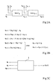
- the Figure 1A represents a series of three MAC type operators in series, MAC1, MAC2 and MAC3.
- the operator MAC1 receives on three input terminals three operands x 1 , y 1 and s 1 .
- the third operator, MAC3 receives two operands x 3 and y 3 , as well as the result s 3 of the operator MAC2.
- the number of calculations requiring operators MAC type is generally very high. To save space and processing time, it is known to group the operators by two as illustrated in relation to the FIGS. 2A to 2C .
- the Figure 2A represents two operators of MAC type, MAC k and MAC k + 1 , connected one after the other.
- the MAC operator k receives operands x k and y k and an operand s k from the previous operator.
- s k + 2 at k + 1 + ⁇ at k + ⁇ s k .
- s k + 2 s k + ⁇ ⁇ at k + ⁇ at k + 1 , because the operation is commutative.
- circuit 1 represented in FIG. Figure 2C , receiving as input three operands, a k , a k + 1 and s k .
- a k corresponds to the saturating multiplication of the operands x k and y k
- a k + 1 corresponds to the saturating multiplication of the operators x k + 1 and y k + 1
- s k corresponds to the result of the preceding circuit.
- Circuit 1 provides a result s k + 2 equal to s k + ⁇ at k + ⁇ at k + 1 .
- the operations providing the operands a k and a k + 1 are executed outside the circuit 1.
- Another object of the present invention is to provide a method and a circuit for carrying out the operation.
- s k + 2 ( s k + ⁇ at k ) + ⁇ at k + 1 particularly fast.
- Another object of the present invention is to provide a fast MAC type circuit and having a number of reduced hardware elements.
- the present invention provides a method, a circuit and a module as defined in the claims.
- the present invention utilizes the positive and negative portions of at least one operand.
- the positive part of the number a k denoted a + k is equal to a k if a k is positive or zero and equal to zero if a k is negative or zero.
- the negative part of a k denoted a - k , is equal to a k if a k is negative or zero and equal to zero if a k is positive or zero.
- the positive and negative parts are calculated very simply from the number and its sign bit, as described below.
- the use of the positive and negative parts of an operand will significantly simplify the circuit performing the operation.
- conventional overshoot circuits are not used.
- the circuit has three inputs E1, E2, E3, respectively receiving three operands s k , a k and a k + 1 .
- the circuit has an output S, providing the result s k + 2 of the operation.
- the operands s k , a k and a k + 1 , as well as the result s k + 2 are signed fractional numbers encoded on n bits.
- the circuit comprises three adders 4, 6 and 8.
- the adder 4 is a three-input adder, each of them receiving one of the three operands a k , a k + 1 and s k . It provides a sum s equal to s k + a k + a k + 1 .
- Adder 6 is a two-way adder. On one of them, it receives the maximum extreme value, max n, which corresponds to the maximum fractional signed signable number on n bits. The other input of the adder 6 receives the negative part a - k + 1 of the third operand. The adder 6 provides a sum equal to max n + a - k + 1 .
- the adder 8 is a two-way adder.
- the adder 8 outputs a sum s "equal to min n + a - k + 1.
- the circuit providing an output on n bits, only the n weakest bits of s, s' and s" can be used later.
- the n least significant bits of s, s' and s can be obtained by simple truncation at the level of adders 4, 6 and 8, or later.
- the min and max values n supplied respectively to the adders 8 and 6, can be stored or determined internally to the circuit. They can also be provided to the circuit, in particular in the case where the circuit is configurable and designed to operate with operands coded on different numbers of bits depending on the applications.
- the positive part a + k + 1 of the operator a k + 1 is determined by a module 10.
- the module 10 consists of a sign extraction module 12 and a gate 11 of the AND (AND) type. on n bits, whose input is inverting.
- the non-inverting input of the gate 11 receives the third operand a k + 1 .
- the gate 11 receives the replicated sign bit in n copies of the operand a k + 1 .
- This bit is provided by the module 12, which receives the operand a k + 1 and replicates in n copies the most significant bit of rank n.
- the output of the gate 11 provides the positive part a + k + 1 of the operand a k + 1 .
- the negative part a - k + 1 of the operand a k + 1 is determined by a module 14.
- the module 14 comprises an AND gate 15 and a sign extraction module 16.
- the module 16 receives the third operand a k + 1 and replicate in n copies its most significant bit, representing the sign of the operand.
- the gate 15 receives on an input the replicated sign bit in n copies of the operand a k + 1 , supplied by the module 16, and on the other input the operand a k + 1 .
- the exit of the gate 15 provides the negative part a - k + 1 of the third operand.
- the circuit calculates two indicators S' and S", the value of which allows the selection of the sum corresponding to the result.
- a three-input adder 20 receives the first operand s k , the second operand a k and the positive portion of the third operand a + k-1 . It provides the sum R 'of these three operands. Since each operand is coded on n bits, the result R 'is provided on n + 2 bits. The result R 'is provided to three bit extraction modules 21, 22 and 23.
- the module 21 provides the nth bit of the result R'.
- the module 22 provides the bit of rank n + 1 of the result R '.
- the module 23 provides the bit of rank n + 2 of the result R '.
- the outputs of the modules 21 and 22 feed an OR type gate (OR).
- the output of the gate 25 supplies a non-inverting input of an AND gate type 26.
- the gate 26 has two inputs, a non-inverting and an inverting.
- the inverting input of the gate 26 receives the bit of rank n + 2 of the result R 'supplied by the module 23.
- the output of the gate 26 provides the indicator S', which is equal to 1 only if the rank bit n + 2 of the result R 'is equal to 0 and one of the two bits of rank n or n + 1 of the result R' is equal to 1.
- the indicator S ' is equal to 1 if s k + a k + a k + 1 > max n + a - k + 1 , which is equivalent to s k + a k + a + k + 1 > max n.
- the indicator S ' is equal to 0 otherwise.
- the assembly constituted by the modules 21, 22, 23 and the doors 25 and 26 constitutes a module 28 indicator of overflow only and is particularly simple to implement.
- a three-input adder 30 receives the first operand s k , the second operand a k and the negative part of the third operand, a - k + 1 . 30 provides, on n + 2 bits, a result R "equal to the sum of the three signals present on its inputs.
- the output of the adder attacks three bit extracting modules 31, 32 and 33.
- the module 31 supplies the bit of rank n of the result R
- the module 32 supplies the bit of rank n + 1 of the result R” and the module 33 supplies the bit of rank n + 2 of the result R "The outputs of the modules 31 and 32 engage a NAND type gate 35.
- the output of the gate 35 drives an input of a two-input AND type gate 36 receiving on its another input, the bit of rank n + 2 of the result R ", supplied by the module 33.
- the output of the gate 36 provides the second indicator S", which is equal to 1 only if the bit of rank n + 2 of the result R "is equal to 1 and one of the two bits of rank n or n + 1 is equal to zero.
- the indicator S " is equal to 1 if s k + a k + a k + 1 ⁇ min n + a + k + 1 , which is equivalent to s k + a k + a - k + 1 ⁇ min n
- the assembly consisting of the modules 31, 32, 33 and the doors 35 and 36 constitutes a module 38 indicator of overflow down particularly simple to implement.
- the output of the gate 26 is connected to a first control input of a multiplexer 40 and the output of the gate 36 is connected to a second control input of the multiplexer 40.
- the multiplexer 40 comprises three inputs, respectively receiving the sums. s' and s ", where appropriate the n least significant bits of these sums.
- the indicators S 'and S" control the multiplexer 40 so that the multiplexer selects the sum s' and supplies the n least significant bits of this sum if the indicator S 'is equal to 1.
- the multiplexer 40 selects the sum s "and provides the n least bits of this sum if the indicator S" is equal to 1. In other cases, the multiplexer provides the n lowest bits of the sum s.
- the output of the multiplexer is connected to the output S of the circuit. It should be noted that the indicators S 'and S "can not be equal to 1 at the same time.
- the circuit of the figure 3 is particularly advantageous because it uses few elements. For example, it uses only one multiplexer 40. Moreover, one of the problems of the prior art solved by the invention relates to the passing circuits. Indeed, in the present invention, not only the use of conventional overshoot modules, calculating both an overshoot upwards and downwards, is avoided, but the calculation of the indicators S 'and S ", witnesses either of an overshoot upwards or downwards is performed in parallel with the calculation of sums, without having to wait for the result of the sums.
- the simplification of the circuit and the saving of time are significant.
- CMOS electronic circuits it is possible to reduce the power consumption significantly by lowering the supply voltage, at the cost of an increase in propagation delays.The time saved by the circuit can thus be exploited to reduce the power consumption. power consumption.
- circuits used in the circuit are extremely fast. All calculations can be provided in less than one clock cycle.
- insertion of such a circuit in a signal processing processor or a dedicated hardware block allows a significant improvement in performance in many applications, including applications where the treatment must be performed exactly to the nearest bit. Indeed, the use of this circuit makes it possible to sum with saturation twice as many operands per cycle as in the case where adders with conventional saturation are used.
- n the number of bits on which the operands are coded, can be arbitrary.
- n can be 32.
- the circuit of the present invention can be easily supplemented to perform the function of a MAC type circuit, the computation of the operands a k and a k + 1 being integrated in the circuit.
Claims (7)
- Ein Verfahren zum Bestimmen, mittels einer Schaltung, eines Ergebnisses (sk+2) von einer Operation des Typs

wobei sk, ak, und ak+1 gebrochene vorzeichenbehaftete Operanden sind und das Symboleine saturierende Additionsoperation repräsentiert, das heißt eine Addition bei der das Ergebnis, falls notwendig, zurückgebracht wird auf einen Grenzwert, der durch die gebrochene Repräsentation zugelassen wird, und zwar im Falle, dass dieser Grenzwert überschritten wird, wobei das Verfahren Folgendes aufweist: - einen Schritt zur Berechnung von drei Summen (s, s', s"), repräsentativ für einen möglichen Wert von dem Ergebnis (sk+2), und- einen Schritt zur Auswahl von einer von den drei Summen,wobei der Schritt zur Berechnung von den drei Summen Folgendes aufweist:- die Bestimmung von den positiven und negativen Teilen von dem Operanden ak+1,- die Berechnung von einer ersten Summe (s), definiert durch
 - die Berechnung von einer zweiten Summe (s'), definiert durch
und- die Berechnung von einer dritten Summe (s"), definiert durch - wobei max n der Wert von der maximalen gebrochenen vorzeichenbehafteten Zahl ist,- min n der Wert von der minimalen gebrochenen vorzeichenbehafteten Zahl ist,
a+ k+1 der positive Teil von dem Operanden ak+1 und a- k+1 der negative Teil von dem Operanden ak+1 ist, der positive Teil von einem Operanden definiert ist als sei er gleich dem Operanden, falls der Operand eine positive Zahl ist und anderenfalls gleich null, der negative Teil von einem Operanden definiert ist als sei er gleich dem Operanden, falls der Operand eine negative Zahl ist und anderenfalls gleich null,
und wobei der Auswahlschritt einen Schritt aufweist zur Berechnung von einem ersten Indikator (S') und von einem zweiten Indikator (S") und ein Ergebnis (sk+2) vorsieht das gleich ist zu:- der zweiten Summe (s'), falls der erste Indikator (S') anzeigt, dass - der dritten Summe (s"), falls der zweite Indikator (S") anzeigt, dass
und- der ersten Summe (s) in allen anderen Fällen,wobei bei dem Verfahren, bei dem der positive Teil von dem dritten Operanden ak+1 während der Berechnung Schritte von der dritten Summe (s") genutzt wird und während der Berechnung Schritte von dem ersten Indikator (S') genutzt wird, und bei dem der negative Teil von dem dritten Operanden ak+1 während der Berechnung Schritte von der zweiten Summe (s') und während der Berechnung Schritte von dem zweiten Indikator (S") genutzt wird. - Verfahren nach Anspruch 1, wobei der Schritt zur Berechnung von den Summen (s, s', s") und der Schritt zur Berechnung von den ersten und zweiten Indikatoren parallel ausgeführt werden.
- Eine Schaltung zum Bestimmen eines Ergebnisses (sk+2) von einer Operation des Typs

wobei sk, ak, und ak+1 entsprechend erste, zweite und dritte Operanden sind, die repräsentiert sind in der Form von vorzeichenbehafteten gebrochenen bzw. fraktionalen Zahlen, die über n Bits kodiert sind, wobei das Symboleine saturierende Additionsoperation repräsentiert, das heißt eine Addition, bei der das Ergebnis, falls notwendig, zurückgebracht wird auf einen Grenzwert, der durch die gebrochene Repräsentation zugelassen wird, und zwar in dem Fall, in dem dieser Grenzwert überschritten wird, wobei die Schaltung Folgendes aufweist: - Mittel (4, 6, 8, 10, 14) zum Berechnen von drei Summen (s, s', s"), die repräsentativ sind für einen möglichen Wert von dem Ergebnis (sk+2), verbunden zum Empfangen der ersten, zweiten und dritten Operanden, und- Mittel (20, 28, 30, 38, 40) zum Auswählen einer von den drei Summen, gekoppelt mit den Berechnungsmitteln,wobei die Mittel zum Berechnen der drei Summen angepasst sind für:- die Bestimmung von den positiven und negativen Teilen von dem Operanden ak+1,- die Berechnung von einer ersten Summe (s), definiert durch
 - die Berechnung von einer zweiten Summe (s'), definiert durch
und- die Berechnung von einer dritten Summe (s"), definiert durchwobei max n der Wert von der maximalen gebrochenen vorzeichenbehafteten Zahl ist, min n der Wert von der minimalen gebrochenen vorzeichenbehafteten Zahl ist,
a+ k+1 der positive Teil von dem Operanden ak+1 ist und a- k+1 der negative Teil von dem Operanden ak+1 ist, der positive Teil von einem Operanden definiert ist als sei er gleich dem Operanden, falls der Operand eine positive Zahl ist und anderenfalls gleich null, der negative Teil von einem Operanden definiert ist als sei er gleich dem Operanden, falls der Operand eine negative Zahl ist und gleich null anderenfalls,
und wobei die Schaltung angepasst ist sodass die Auswahlmittel einen ersten Indikator (S') und einen zweiten Indikator (S") berechnen und ein Ergebnis (sk+2) vorsehen, und zwar gleich zu:- der zweiten Summe (s'), falls der erste Indikator (S') anzeigt, dass
ist,- der dritten Summe (s"), falls der zweite Indikator (S") anzeigt, dass
ist, und- der ersten Summe (s), in allen anderen Fällen, die Schaltung angepasst ist derart, dass der positive Teil von dem dritten Operanden ak+1, während den Berechnungsschritten von der dritten Summe (s") und während den Berechnungsschritten von dem ersten Indikator (S') genutzt wird und wobei der negative Teil von dem dritten Operanden ak+1 während den Berechnungsschritten von der zweiten Summe (s') und während den Berechnungsschritten von dem zweiten Indikator (S") genutzt wird. - Schaltung nach Anspruch 3, wobei die Berechnungsmittel Folgendes aufweisen:- ein UND Gatter (11), angesteuert durch den dritten Operanden (ak+1) und dem Inversen von dem n Mal replizierten Vorzeichenbit von dem dritten Operanden zum Vorsehen des positiven Teils von dem dritten Operanden (a+ k+1), und- ein UND Gatter (15), angesteuert durch den dritten Operanden (ak+1) und dem n Mal replizierten Vorzeichenbit von dem dritten Operanden zum Vorsehen des negativen Teils von dem dritten Operanden (a- k+1).
- Schaltung nach Anspruch 4, wobei die Berechnungsmittel ferner Folgendes aufweisen:- einen ersten Addierer (4) zum Empfangen der ersten, zweiten und dritten Operanden und zum Vorsehen der ersten Summe (s),- einen zweiten Addierer (6) zum Vorsehen der zweiten Summe (s') und zum Empfangen des negativen Teils (a- k+1) von dem dritten Operanden und dem Wert von der maximalen gebrochenen vorzeichenbehafteten Zahl und zwar über n Bits (max n) kodiert, und- einen dritten Addierer (8) zum Vorsehen der dritten Summe (s") und zum Empfangen des positiven Teils von dem dritten Operanden (a+ k+1) und dem Wert von der minimalen gebrochenen vorzeichenbehafteten Zahl und zwar kodiert über n Bits (min n).
- Schaltung nach Anspruch 4 oder 5, wobei die Auswahlmittel Folgendes aufweisen:- einen vierten Addierer (20), zum Empfangen des ersten Operanden, des zweiten Operanden und des positiven Teils von dem dritten Operanden, berechnet durch die Berechnungsmittel,- eine Einheit zum Anzeigen eines aufwärtigen Überlaufs (28), zum Empfangen des Ergebnisses von dem vierten Addierer (20) und zum Vorsehen des ersten Indikators (S'),- einen fünften Addierer (30), zum Empfangen des ersten Operanden, des zweiten Operanden und des negativen Teils von dem dritten Operanden, berechnet durch die Berechnungsmittel,- eine Einheit zum Anzeigen eines abwärtigen Überlaufs (38), zum Empfangen des Ergebnisses von dem fünften Addierer (30) und zum Vorsehen des zweiten Indikators (S"), und- einen Multiplexer (40) zum Empfangen der ersten, zweiten und dritten Summen, berechnet durch die Berechnungsmittel und zum Vorsehen des Ergebnisses sk+2 von der Operation, wobei der Multiplexer angepasst ist, um durch die ersten und zweiten Indikatoren gesteuert zu werden.
- Eine Einheit zum Ausführen einer Funktion vom MAC-Typ, dadurch gekennzeichnet, dass sie angepasst ist zum Nutzen des Verfahrens nach Anspruch 1 oder 2 oder dass sie die Schaltung nach irgendeinem der Ansprüche 3 bis 6 aufweist.
Applications Claiming Priority (2)
| Application Number | Priority Date | Filing Date | Title |
|---|---|---|---|
| FR0201569 | 2002-02-08 | ||
| FR0201569A FR2835938A1 (fr) | 2002-02-08 | 2002-02-08 | Operateur saturant a haute efficacite |
Publications (2)
| Publication Number | Publication Date |
|---|---|
| EP1335277A1 EP1335277A1 (de) | 2003-08-13 |
| EP1335277B1 true EP1335277B1 (de) | 2009-08-12 |
Family
ID=27589611
Family Applications (1)
| Application Number | Title | Priority Date | Filing Date |
|---|---|---|---|
| EP03354010A Expired - Fee Related EP1335277B1 (de) | 2002-02-08 | 2003-02-06 | Effiziente sättigende Operation |
Country Status (4)
| Country | Link |
|---|---|
| US (1) | US7177893B2 (de) |
| EP (1) | EP1335277B1 (de) |
| DE (1) | DE60328738D1 (de) |
| FR (1) | FR2835938A1 (de) |
Families Citing this family (3)
| Publication number | Priority date | Publication date | Assignee | Title |
|---|---|---|---|---|
| JP2008522304A (ja) * | 2004-12-01 | 2008-06-26 | エヌエックスピー ビー ヴィ | マルチオペランド演算回路を有する電子装置 |
| US8352531B2 (en) * | 2008-07-22 | 2013-01-08 | International Business Machines Corporation | Efficient forcing of corner cases in a floating point rounder |
| US10564931B1 (en) * | 2018-04-05 | 2020-02-18 | Apple Inc. | Floating-point arithmetic operation range exception override circuit |
Family Cites Families (7)
| Publication number | Priority date | Publication date | Assignee | Title |
|---|---|---|---|---|
| US4215415A (en) * | 1977-09-19 | 1980-07-29 | Nippon Electric Company, Ltd. | Recursive digital filter comprising a circuit responsive to first sum and feedback sign bits and second sum sign and integer bits for detecting overflow in the second sum |
| JPH0997178A (ja) * | 1995-09-29 | 1997-04-08 | Matsushita Electric Ind Co Ltd | 飽和演算処理装置および方法 |
| US6209017B1 (en) * | 1997-08-30 | 2001-03-27 | Lg Electronics Inc. | High speed digital signal processor |
| US5889689A (en) * | 1997-09-08 | 1999-03-30 | Lucent Technologies Inc. | Hierarchical carry-select, three-input saturation |
| US6182105B1 (en) * | 1998-08-27 | 2001-01-30 | Lucent Technologies Inc. | Multiple-operand addition with intermediate saturation |
| US6519620B1 (en) * | 1999-04-22 | 2003-02-11 | International Business Machines Corporation | Saturation select apparatus and method therefor |
| US6499046B1 (en) * | 1999-05-20 | 2002-12-24 | International Business Machines Corporation | Saturation detection apparatus and method therefor |
-
2002
- 2002-02-08 FR FR0201569A patent/FR2835938A1/fr active Pending
-
2003
- 2003-02-06 EP EP03354010A patent/EP1335277B1/de not_active Expired - Fee Related
- 2003-02-06 DE DE60328738T patent/DE60328738D1/de not_active Expired - Lifetime
- 2003-02-07 US US10/360,831 patent/US7177893B2/en active Active
Also Published As
| Publication number | Publication date |
|---|---|
| FR2835938A1 (fr) | 2003-08-15 |
| US20030169077A1 (en) | 2003-09-11 |
| EP1335277A1 (de) | 2003-08-13 |
| US7177893B2 (en) | 2007-02-13 |
| DE60328738D1 (de) | 2009-09-24 |
Similar Documents
| Publication | Publication Date | Title |
|---|---|---|
| CN110222833B (zh) | 一种用于神经网络的数据处理电路 | |
| Kumar et al. | A New Fast and Area-Efficient Adder-Based Sign Detector for RNS {$2^{n}-1, 2^{n}, 2^{n}+ 1$} | |
| EP0692762A1 (de) | Logikschaltung zur parallelen Multiplikation | |
| FR2793971A1 (fr) | Multiplieur de nombres complexes | |
| FR2849512A1 (fr) | Multiplieur modulaire de montgomery et procede de multiplication correspondant | |
| EP0437876B1 (de) | Programmierbarer serieller Multiplikator | |
| EP1335277B1 (de) | Effiziente sättigende Operation | |
| US6574649B2 (en) | Efficient convolution method and apparatus | |
| Sadangi et al. | FPGA implementation of spatial filtering techniques for 2D images | |
| FR3097993A1 (fr) | Opérateur de produit scalaire de nombres à virgule flottante réalisant un arrondi correct | |
| EP0237382B1 (de) | Gerät zur Kosinustransformation eines abgetasteten digitalen Signals | |
| Zhang et al. | FPGA-based approximate multiplier for efficient neural computation | |
| CN114201140B (zh) | 指数函数处理单元、方法和神经网络芯片 | |
| Perlow et al. | Finite wordlength design for VLSI FFT processors | |
| FR3097992A1 (fr) | Opérateur d’addition et multiplication fusionnées pour nombres à virgule flottante de précision mixte réalisant un arrondi correct | |
| Cohen et al. | Complex floating point—a novel data word representation for DSP processors | |
| EP0175623A1 (de) | Einrichtung zur Echtzeitdigitalsignalverarbeitung durch Faltung | |
| EP0341097B1 (de) | Rekursiver Addierer zur Berechnung der Summe zweier Operanden | |
| FR2530854A1 (fr) | Procede d'execution d'un traitement mathematique a l'aide d'une memoire permanente et dispositif d'adressage pour sa mise en oeuvre | |
| Atitallah et al. | Reconfigurable architecture of VDF filter for multidimensional data | |
| Wang et al. | Novel design and FPGA implementation of DA-RNS FIR filters | |
| FR2731813A1 (fr) | Processeur informatique utilisant la conversion logarithmique et son procede d'utilisation | |
| JPH09245019A (ja) | 積和演算回路 | |
| EP0718755B1 (de) | Elektronisches Bauelement, insbesondere fähig zum Ausführen einer Division zur Basis 4 von zwei Zahlen | |
| FR2585150A1 (fr) | Multiplieur pour la multiplication de deux nombres complexes |
Legal Events
| Date | Code | Title | Description |
|---|---|---|---|
| PUAI | Public reference made under article 153(3) epc to a published international application that has entered the european phase |
Free format text: ORIGINAL CODE: 0009012 |
|
| AK | Designated contracting states |
Designated state(s): AT BE BG CH CY CZ DE DK EE ES FI FR GB GR HU IE IT LI LU MC NL PT SE SI SK TR |
|
| AX | Request for extension of the european patent |
Extension state: AL LT LV MK RO |
|
| 17P | Request for examination filed |
Effective date: 20040203 |
|
| AKX | Designation fees paid |
Designated state(s): DE FR GB IT |
|
| 17Q | First examination report despatched |
Effective date: 20040428 |
|
| 17Q | First examination report despatched |
Effective date: 20040428 |
|
| RIC1 | Information provided on ipc code assigned before grant |
Ipc: G06F 7/499 20060101AFI20080829BHEP Ipc: G06F 7/509 20060101ALI20080829BHEP Ipc: G06F 7/50 20060101ALI20080829BHEP Ipc: G06F 7/544 20060101ALN20080829BHEP |
|
| GRAP | Despatch of communication of intention to grant a patent |
Free format text: ORIGINAL CODE: EPIDOSNIGR1 |
|
| GRAS | Grant fee paid |
Free format text: ORIGINAL CODE: EPIDOSNIGR3 |
|
| GRAA | (expected) grant |
Free format text: ORIGINAL CODE: 0009210 |
|
| AK | Designated contracting states |
Kind code of ref document: B1 Designated state(s): DE FR GB IT |
|
| REG | Reference to a national code |
Ref country code: GB Ref legal event code: FG4D Free format text: NOT ENGLISH |
|
| REF | Corresponds to: |
Ref document number: 60328738 Country of ref document: DE Date of ref document: 20090924 Kind code of ref document: P |
|
| PLBE | No opposition filed within time limit |
Free format text: ORIGINAL CODE: 0009261 |
|
| STAA | Information on the status of an ep patent application or granted ep patent |
Free format text: STATUS: NO OPPOSITION FILED WITHIN TIME LIMIT |
|
| 26N | No opposition filed |
Effective date: 20100517 |
|
| REG | Reference to a national code |
Ref country code: FR Ref legal event code: ST Effective date: 20101029 |
|
| PG25 | Lapsed in a contracting state [announced via postgrant information from national office to epo] |
Ref country code: FR Free format text: LAPSE BECAUSE OF NON-PAYMENT OF DUE FEES Effective date: 20100301 |
|
| PG25 | Lapsed in a contracting state [announced via postgrant information from national office to epo] |
Ref country code: IT Free format text: LAPSE BECAUSE OF FAILURE TO SUBMIT A TRANSLATION OF THE DESCRIPTION OR TO PAY THE FEE WITHIN THE PRESCRIBED TIME-LIMIT Effective date: 20090812 |
|
| PGFP | Annual fee paid to national office [announced via postgrant information from national office to epo] |
Ref country code: GB Payment date: 20110128 Year of fee payment: 9 |
|
| PGFP | Annual fee paid to national office [announced via postgrant information from national office to epo] |
Ref country code: DE Payment date: 20120123 Year of fee payment: 10 |
|
| GBPC | Gb: european patent ceased through non-payment of renewal fee |
Effective date: 20120206 |
|
| PG25 | Lapsed in a contracting state [announced via postgrant information from national office to epo] |
Ref country code: GB Free format text: LAPSE BECAUSE OF NON-PAYMENT OF DUE FEES Effective date: 20120206 |
|
| REG | Reference to a national code |
Ref country code: DE Ref legal event code: R119 Ref document number: 60328738 Country of ref document: DE Effective date: 20130903 |
|
| PG25 | Lapsed in a contracting state [announced via postgrant information from national office to epo] |
Ref country code: DE Free format text: LAPSE BECAUSE OF NON-PAYMENT OF DUE FEES Effective date: 20130903 |