EP1335115A2 - Internal combustion engine provided with decompressing means - Google Patents
Internal combustion engine provided with decompressing means Download PDFInfo
- Publication number
- EP1335115A2 EP1335115A2 EP03250607A EP03250607A EP1335115A2 EP 1335115 A2 EP1335115 A2 EP 1335115A2 EP 03250607 A EP03250607 A EP 03250607A EP 03250607 A EP03250607 A EP 03250607A EP 1335115 A2 EP1335115 A2 EP 1335115A2
- Authority
- EP
- European Patent Office
- Prior art keywords
- flyweight
- camshaft
- arm
- axis
- internal combustion
- Prior art date
- Legal status (The legal status is an assumption and is not a legal conclusion. Google has not performed a legal analysis and makes no representation as to the accuracy of the status listed.)
- Granted
Links
- 238000002485 combustion reaction Methods 0.000 title claims abstract description 53
- 230000006837 decompression Effects 0.000 claims abstract description 100
- 230000033001 locomotion Effects 0.000 claims abstract description 62
- 230000006835 compression Effects 0.000 claims description 8
- 238000007906 compression Methods 0.000 claims description 8
- 239000002184 metal Substances 0.000 claims description 8
- 229910052751 metal Inorganic materials 0.000 claims description 8
- 238000002347 injection Methods 0.000 claims description 6
- 239000007924 injection Substances 0.000 claims description 6
- 230000007246 mechanism Effects 0.000 abstract description 47
- 239000003921 oil Substances 0.000 description 43
- 239000010687 lubricating oil Substances 0.000 description 12
- 230000005484 gravity Effects 0.000 description 10
- 239000007858 starting material Substances 0.000 description 10
- 239000000446 fuel Substances 0.000 description 6
- 239000012141 concentrate Substances 0.000 description 4
- 238000000034 method Methods 0.000 description 4
- 239000000203 mixture Substances 0.000 description 4
- 238000005299 abrasion Methods 0.000 description 3
- 230000000694 effects Effects 0.000 description 3
- 238000000465 moulding Methods 0.000 description 3
- 238000003825 pressing Methods 0.000 description 3
- 230000009467 reduction Effects 0.000 description 3
- PXHVJJICTQNCMI-UHFFFAOYSA-N Nickel Chemical compound [Ni] PXHVJJICTQNCMI-UHFFFAOYSA-N 0.000 description 2
- 238000013459 approach Methods 0.000 description 2
- 238000005520 cutting process Methods 0.000 description 2
- 230000001050 lubricating effect Effects 0.000 description 2
- 230000004048 modification Effects 0.000 description 2
- 238000012986 modification Methods 0.000 description 2
- 210000003371 toe Anatomy 0.000 description 2
- 229910000640 Fe alloy Inorganic materials 0.000 description 1
- 230000005540 biological transmission Effects 0.000 description 1
- 238000005266 casting Methods 0.000 description 1
- 239000000567 combustion gas Substances 0.000 description 1
- 238000010276 construction Methods 0.000 description 1
- 230000008878 coupling Effects 0.000 description 1
- 238000010168 coupling process Methods 0.000 description 1
- 238000005859 coupling reaction Methods 0.000 description 1
- 238000000354 decomposition reaction Methods 0.000 description 1
- 230000007423 decrease Effects 0.000 description 1
- 230000001747 exhibiting effect Effects 0.000 description 1
- 210000003414 extremity Anatomy 0.000 description 1
- 239000007789 gas Substances 0.000 description 1
- 238000001746 injection moulding Methods 0.000 description 1
- 238000004519 manufacturing process Methods 0.000 description 1
- 229910052759 nickel Inorganic materials 0.000 description 1
- 239000000843 powder Substances 0.000 description 1
- 230000008569 process Effects 0.000 description 1
- 239000011435 rock Substances 0.000 description 1
- 238000005245 sintering Methods 0.000 description 1
- 230000001629 suppression Effects 0.000 description 1
Images


Classifications
-
- F—MECHANICAL ENGINEERING; LIGHTING; HEATING; WEAPONS; BLASTING
- F02—COMBUSTION ENGINES; HOT-GAS OR COMBUSTION-PRODUCT ENGINE PLANTS
- F02B—INTERNAL-COMBUSTION PISTON ENGINES; COMBUSTION ENGINES IN GENERAL
- F02B75/00—Other engines
- F02B75/16—Engines characterised by number of cylinders, e.g. single-cylinder engines
- F02B75/18—Multi-cylinder engines
- F02B75/20—Multi-cylinder engines with cylinders all in one line
-
- F—MECHANICAL ENGINEERING; LIGHTING; HEATING; WEAPONS; BLASTING
- F01—MACHINES OR ENGINES IN GENERAL; ENGINE PLANTS IN GENERAL; STEAM ENGINES
- F01L—CYCLICALLY OPERATING VALVES FOR MACHINES OR ENGINES
- F01L13/00—Modifications of valve-gear to facilitate reversing, braking, starting, changing compression ratio, or other specific operations
- F01L13/08—Modifications of valve-gear to facilitate reversing, braking, starting, changing compression ratio, or other specific operations for decompression, e.g. during starting; for changing compression ratio
- F01L13/085—Modifications of valve-gear to facilitate reversing, braking, starting, changing compression ratio, or other specific operations for decompression, e.g. during starting; for changing compression ratio the valve-gear having an auxiliary cam protruding from the main cam profile
-
- F—MECHANICAL ENGINEERING; LIGHTING; HEATING; WEAPONS; BLASTING
- F02—COMBUSTION ENGINES; HOT-GAS OR COMBUSTION-PRODUCT ENGINE PLANTS
- F02B—INTERNAL-COMBUSTION PISTON ENGINES; COMBUSTION ENGINES IN GENERAL
- F02B61/00—Adaptations of engines for driving vehicles or for driving propellers; Combinations of engines with gearing
- F02B61/04—Adaptations of engines for driving vehicles or for driving propellers; Combinations of engines with gearing for driving propellers
- F02B61/045—Adaptations of engines for driving vehicles or for driving propellers; Combinations of engines with gearing for driving propellers for marine engines
-
- F—MECHANICAL ENGINEERING; LIGHTING; HEATING; WEAPONS; BLASTING
- F01—MACHINES OR ENGINES IN GENERAL; ENGINE PLANTS IN GENERAL; STEAM ENGINES
- F01L—CYCLICALLY OPERATING VALVES FOR MACHINES OR ENGINES
- F01L1/00—Valve-gear or valve arrangements, e.g. lift-valve gear
- F01L1/02—Valve drive
- F01L1/024—Belt drive
-
- F—MECHANICAL ENGINEERING; LIGHTING; HEATING; WEAPONS; BLASTING
- F01—MACHINES OR ENGINES IN GENERAL; ENGINE PLANTS IN GENERAL; STEAM ENGINES
- F01L—CYCLICALLY OPERATING VALVES FOR MACHINES OR ENGINES
- F01L1/00—Valve-gear or valve arrangements, e.g. lift-valve gear
- F01L1/02—Valve drive
- F01L1/04—Valve drive by means of cams, camshafts, cam discs, eccentrics or the like
- F01L1/047—Camshafts
- F01L1/053—Camshafts overhead type
- F01L2001/0535—Single overhead camshafts [SOHC]
-
- F—MECHANICAL ENGINEERING; LIGHTING; HEATING; WEAPONS; BLASTING
- F01—MACHINES OR ENGINES IN GENERAL; ENGINE PLANTS IN GENERAL; STEAM ENGINES
- F01L—CYCLICALLY OPERATING VALVES FOR MACHINES OR ENGINES
- F01L2301/00—Using particular materials
-
- F—MECHANICAL ENGINEERING; LIGHTING; HEATING; WEAPONS; BLASTING
- F02—COMBUSTION ENGINES; HOT-GAS OR COMBUSTION-PRODUCT ENGINE PLANTS
- F02B—INTERNAL-COMBUSTION PISTON ENGINES; COMBUSTION ENGINES IN GENERAL
- F02B75/00—Other engines
- F02B75/02—Engines characterised by their cycles, e.g. six-stroke
- F02B2075/022—Engines characterised by their cycles, e.g. six-stroke having less than six strokes per cycle
- F02B2075/027—Engines characterised by their cycles, e.g. six-stroke having less than six strokes per cycle four
-
- F—MECHANICAL ENGINEERING; LIGHTING; HEATING; WEAPONS; BLASTING
- F02—COMBUSTION ENGINES; HOT-GAS OR COMBUSTION-PRODUCT ENGINE PLANTS
- F02B—INTERNAL-COMBUSTION PISTON ENGINES; COMBUSTION ENGINES IN GENERAL
- F02B75/00—Other engines
- F02B75/16—Engines characterised by number of cylinders, e.g. single-cylinder engines
- F02B75/18—Multi-cylinder engines
- F02B2075/1804—Number of cylinders
- F02B2075/1808—Number of cylinders two
Definitions
- the present invention relates to an internal combustion engine provided with a centrifugal decompressing means for reducing compression pressure to facilitate staring the internal combustion engine by opening a valve included in the internal combustion engine during the compression stroke in starting the internal combustion engine.
- the decompressing means of those known techniques which will be referred to as "prior art A"
- the lever is supported for turning at two parts thereof diametrically facing a camshaft by a pin on the camshaft.
- the decompression cam is connected to the weight by two arms extending from the two parts of the lever supported by the pin.
- Centrifugal decompressing means of techniques disclosed in JP63-246406A and U.S. Pat. No. 3,395,689 which will be referred to as "prior art B"
- a lever provided with a weight and a decompression cam, and having the shape of a flat plate of a substantially uniform thickness.
- the lever is supported for turning at one part thereof by a pin on a camshaft. Therefore, the decompression cam is connected to the weight by a single arm extending from the one part of the lever supported by the pin.
- the weight capable of swinging on the pin relative to the camshaft overlaps the camshaft as viewed from a direction perpendicular to a plane including the axis of rotation of the camshaft and parallel to the axis of swing motion or a to a plane including the axis of rotation of the camshaft and a plane including the axis of swing motion.
- the lever which corresponds to a decompression member, has the two arms and hence the mass ratio of the weight to the lever is low. Therefore, it is difficult to concentrate a large part of the mass of the lever on the weight to generate a high centrifugal force necessary for stopping a decompressing operation at a set engine speed without increasing the weight of the lever.
- the size of the lever increases and the diameter of a cylindrical space in which the fully expanded lever revolves around the camshaft increases, the layout of members in a valve gear chamber in which the camshaft is disposed is subject to restrictions, and the weight of the lever increases.
- the lever corresponding to a decompression member is provided with the single arm. Therefore, the mass ratio of the weight to the lever of the decompressing means of the prior art B is greater than that of the weight to the lever of the decompressing means of the prior art A.
- the thickness of the weight is equal to that of the arm, i.e., the thickness of a plate forming the lever, it is difficult to concentrate mass on the weight simultaneously with the reduction of the size of the decompressing means.
- the lever needs to be bent or an additional member needs to be attached to the lever to concentrate mass on the weight included integrally with the lever formed from a plate of a uniform thickness.
- concentration of mass on the weight increases working steps, and requires difficult work because the lever has a complicated shape. Consequently, the respective operating characteristics of such complicated levers, i.e., decompression members, are distributed in a wide range.
- a third object of the present invention is to facilitate the manufacture of decompressing means respectively having operating characteristics distributed in a narrow range.
- an internal combustion engine comprises a crankshaft, a camshaft driven for rotation in synchronism with the crankshaft, a valve-operating cam formed on the camshaft, engine valves operated for opening and closing by the valve-operating cam, and a decompressing means for opening the engine valve in a compression stroke in a starting phase
- the decompressing means comprises a flyweight supported for swing motion by a pin on the camshaft, a decompression cam that operates together with the flyweight to exert a valve-opening force on the engine valve, and an arm connecting the flyweight and the decompression cam
- the flyweight has a weight body and projections projecting from the weight body and engaged with the pin
- the pin is disposed such that the axis of swing motion of the flyweight is included in a plane substantially perpendicular to the axis of rotation of the camshaft
- the weight body is a block of width along the axis of swing motion and a thickness along a radial direction which are greater than
- the mass ratio of the weight body to the decompressing means is large.
- the weight body is formed in the width along the axis of swing motion greater than the thickness of the arm, and in the thickness in the radial direction greater than the thickness of the arm to form the decompressing means of component parts respectively having different thicknesses.
- the flyweight has a necessary rigidity, the mass of the arm can be reduced to the least possible extent, most part of the mass of the decompressing means is concentrated on the weight body, and the weight body is disposed in a space radially inside the camshaft such that the weight body overlaps the camshaft as viewed from the direction perpendicular to the reference plane.
- the decompressing means thus formed has the following effects. Since the decompressing means includes the flyweight having the weight body and the projections, and the arm, and the weight body has the width and the thickness which are greater than the thickness of the arm, the decompressing means is lightweight and most part of the mass of the decompressing means can be concentrated on the weight body.
- the weight body overlapping the camshaft as viewed form the direction perpendicular to the reference plane suppresses the enlargement of the decompressing means, and therefore the fully expanded decompressing means is able to revolve around the camshaft in a small cylindrical space around the camshaft or the expansion of the cylindrical space can be suppressed.
- the arm may have the shape of a plate, and the thickness of the arm may be equal to the thickness of a plate forming the arm.
- the arm may be extended from the flyweight in a plane perpendicular to the axis of swing motion.
- camshaft has a holding part including projections provided with first holes, respectively, the projections of the flyweight are provided with second holes, respectively, the pin is inserted in the first holes so as to be turnable therein and is inserted in the second holes to support the flyweight for turning, an end part projecting outside from the first or the second hole is pressed to form an expanded part for preventing the pin from coming off the first and the second holes.
- the pin can be prevented from coming off the first and the second holes simply by pressing the end part thereof.
- the arm may be extended from the weight body. Since the projections through which the pin is inserted, and the arm connecting the flyweight and the decompression cam can be thus extended in different directions, respectively, from the weight body, the thicknesses and the shapes of the projections and the arm can be individually determined, and the optimum designing of the positional relation of the flyweight and the arm with the camshaft, the projections, the weight body and the arm is possible.
- the flyweight, the decompression cam and the arm can be formed integrally in a single structure by metal injection.
- the decompressing means is formed by integrally combining the component parts respectively having different thicknesses, the flyweight, the decompression cam and the arm can be formed in high dimensional accuracy. Since the flyweight, the decompression cam and the arm respectively having different thicknesses are formed integrally in high dimensional accuracy, the decompressing means has an operating characteristic in a narrow range around a reference operating characteristic, and the decompressing means capable of exhibiting stable operating characteristic can be easily manufactured.
- the crankshaft has a vertical axis of rotation, a cut part for receiving the flyweight therein is formed in the outer surface of the camshaft, and the decompressing means includes a return spring that exerts resilient force on the flyweight received in the cut part to hold the flyweight at an initial position.
- a second cut for receiving the arm connecting the flyweight and the decompression cam, and the decompression cam therein may be formed in the outer surface of the camshaft, and the arm may be provided with a contact protrusion that rests on the camshaft to locate the flyweight at a full-expansion position.
- the second cut part may be provided with a step with which the arm comes into contact.
- the second cut part has a bottom surface along which the arm slides when the flyweight swings.
- the expression, 'substantially perpendicular' is used for expressing both an exactly perpendicularly intersecting condition and an approximately perpendicularly intersecting condition.
- Terms, 'diametrical direction' and 'circumferential direction' signify a direction parallel to a diameter of the camshaft and a direction along the outer surface of the camshaft, respectively, unless otherwise specified.
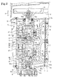
- an internal combustion engine E provided with decompressing mechanisms D is a water-cooled, inline, two-cylinder, four-stroke-cycle, vertical internal combustion engine installed in an outboard motor with the axis of rotation of its crankshaft 8 vertically extended.
- the internal combustion engine E comprises a cylinder block 2 provided with two cylinder bores 2a in a vertical, parallel arrangement with their axes longitudinally horizontally extended, a crankcase 3 joined to the front end of the cylinder block 2; a cylinder head 4 joined to the rear end of the cylinder block 2; and a cylinder head cover joined to the rear end of the cylinder head 4.
- the cylinder block 2, the crankcase 3, the cylinder head 4 and the cylinder head cover 5 constitute an engine body.
- a piston 6 is fitted for reciprocating sliding motions in each of the cylinder bores 2a and is connected to a crankshaft 8 by a connecting rod 7.
- the crankshaft 8 is installed in a crank chamber 9 and is supported for rotation in upper and lower plain bearings on the cylinder block 2 and the crankcase 3.
- the crankshaft 8 is driven for rotation by the pistons 6 driven by combustion pressure produced by the combustion of an air-fuel mixture ignited by spark plugs.
- phase difference between the pistons 6 fitted in the two cylinder bores 2a corresponds to a crank angle of 360°. Therefore, combustion occurs alternately in the cylinder bores 2a at equal angular intervals in this internal combustion engine E.
- a crankshaft pulley 11 and a rewind starter 13 are mounted in that order on an upper end part of the crankshaft 8 projecting upward from the crank changer 9.
- a camshaft 15 is installed in a valve gear chamber 14 defined by the cylinder head 4 and the cylinder head cover 5 and is supported for rotation on the cylinder head 4 with its axis L1 of rotation extended in parallel with that of the crankshaft 8.
- a camshaft pulley 16 is mounted on an upper end part 15a of the camshaft 15 projecting upward from the valve gear chamber 14.
- the camshaft 15 is driven for rotation in synchronism with the crankshaft 8 at a rotating speed equal to half that of the crankshaft 8 by the crankshaft 8 through a transmission mechanism including the crankshaft pulley 11, the camshaft pulley 16 and a timing belt 17 extended between the pulleys 11 and 16.
- a lower end part 15b of the camshaft 15 is coupled by a shaft coupling 19 with a pump drive shaft 18a connected to the inner rotor 18b of a trochoid oil pump 18 attached to the lower end wall of the cylinder head 4.
- the engine body is joined to the upper end of a support block 20.
- An extension case 21 has an upper end joined to the lower end of the support block 20 and a lower end joined to a gear case 22.
- An under cover 23 joined to the upper end of the extension case 21 covers a lower half part of the engine body and the support block 20.
- An engine cover 24 joined to the upper end of the under cover 23 covers an upper half part of the engine body.
- a drive shaft 25 connected to a lower end part of the crankshaft 8 extends downward through the support block 20 and the extension case 21, and is connected to a propeller shaft 27 by a propelling direction switching device 26 including a bevel gear mechanism and a clutch mechanism.
- the power of the internal combustion engine e is transmitted through the crankshaft 8, the drive shaft 25, a propelling direction switching device 26 and the propeller shaft 27 to a propeller 28 fixedly mounted on a rear end part of the propeller shaft 27 to drive the propeller 28 for rotation.
- the outboard motor 1 is detachably connected to a hull 30 by a transom clamp 31.
- a swing arm 33 is supported for swing motions in a vertical plane by a tilt shaft 32 on the transom clamp 31.
- a tubular swivel case 34 is connected to the rear end of the swing arm 33.
- a swivel shaft 35 fitted for rotation in the swivel case 34 has an upper end part provided with a mounting frame 36 and a lower end part provided with a center housing 37.
- the mounting frame 36 is connected elastically through a rubber mount 38a to the support block 20.
- the center housing 37 is connected elastically through a rubber mount 38b to the extension case 21.
- a steering arm is connected to the front end of the mounting frame 36. The steering arm is turned in a horizontal plane for controlling the direction of the outboard motor 1.
- An intake port 40 through which an air-fuel mixture prepared by a carburetor, not shown, flows into a combustion chamber 10 and an exhaust port 41 through which combustion gases discharged from the combustion chamber 10 flows are formed for each of the cylinder bores 2a in the cylinder head 4.
- An intake valve 42 that opens and closes the intake port 40 and an exhaust valve 43 that opens and closes the exhaust port 41 are urged always in a closing direction by the resilience of valve springs 44.
- the intake valve 42 and the exhaust valve 43 are operated for opening and closing operations by a valve train installed in the valve gear chamber 14.
- the valve train includes the camshaft 15, valve-operating cams 45 formed on the camshaft 15 so as to correspond to the cylinder bores 2a, intake rocker arms (cam followers) 47 mounted for rocking motion on a rocker shaft 46 fixedly supported on the cylinder head 4 and driven by the valve-operating cams 45, and exhaust rocker arms (cam followers) 48 mounted on the rocker shaft 46 and driven by the valve-operating cams 45.
- Each valve-operating cam 45 has an intake cam part 45i, an exhaust cam part 45e, and a cam surface 45s common to the intake cam part 45i and the exhaust cam part 45e.
- the intake rocker arm 47 has one end part provided with an adjusting screw 47a in contact with the intake valve 42 and the other end provided with a slipper 47b in contact with the cam surface 45s of the intake cam part 45i of the valve-operating cam 45.
- the exhaust rocker arm 48 has one end provided with an adjusting screw 48a in contact with the exhaust valve 43 and the other end provided with a slipper 48b in contact with the cam surface 45s of the exhaust cam part 45e of the valve-operating cam 45.
- the cam surface 45s of the valve-operating cam 45 has a heel 45a of a shape conforming to a base circle for keeping the intake valve 42 and the exhaust valve 43 closed, and a toe 45b that times the operation of the intake valve 42 and the exhaust valve 43 and determines the lift of the intake valve 42 and the exhaust valve 43.
- the valve-operating cams 45 rotate together with the camshaft 15 to rock the intake rocker arms 47 and the exhaust rocker arms 48 to operate the intake valves 42 and the exhaust valves 43.
- the camshaft 15 has the pair of valve-operating cams 45, an upper journal 50a, a lower journal 50b, an upper thrust-bearing part 51a continuous with the upper journal 50a, a lower thrust-bearing part 51b continuous with the lower journal 50b, shaft parts 52 extending between the valve-operating cams 45 and between the valve-operating cam 45 and the lower thrust-bearing part 51b, and a pump-driving cam 53 for driving a fuel pump, not shown.
- the camshaft 15 has a central bore 54 having an open lower end opening in the end surface of the lower end part 15b in which the lower journal 50b is formed, and a closed upper end in the upper journal 50a.
- the bore 54 extends vertically in the direction of the arrow A parallel with the axis of rotation of the camshaft 15.
- the upper journal 50a is supported for rotation in an upper bearing 55a held in the upper wall of the cylinder head 4, and a lower journal 55b is supported for rotation in a lower bearing 55b held in the lower wall of the cylinder head 4.
- Each shaft part 52 has a cylindrical surface 52a having the shape of a circular cylinder of a radius R smaller than the radius of the heel 45a of a shape conforming to the base circle.
- the pump-driving cam 53 is formed on the shaft part 52.
- the pump-driving cam 53 drives a drive arm 56 supported for swinging on the rocker shaft 46 for swing motion to reciprocate the drive rod included in the fuel pump in contact with the drive arm 56.
- FIG. 1 A lubricating system will be described.
- an oil pan 57 is formed in the support block 20.
- a lower end provided with an oil strainer 58 of a suction pipe 59 is immersed in a lubricating oil contained in the oil pan 57.
- the suction pipe 59 has an upper end connected by a joint to an oil passage 60a formed in the cylinder block 2.
- the oil passage 60a communicates with the suction port 18e (Fig. 2) of the oil pump 18 by means of an oil passage 60b formed in the cylinder head 4.
- the discharge port, not shown, of the oil pump 18 is connected through oil passages, not shown, formed in the cylinder head 4 and the cylinder block 2, and an oil filter, not shown, to a main oil passage, not shown, formed in the cylinder block 2.
- a plurality of branch oil passages branch from the main oil passage.
- the branch oil passages are connected to the bearings and sliding parts including the plain bearings supporting the crankshaft 8 of the internal combustion engine E.
- One branch oil passage 61 among the plurality of branch oil passages is formed in the cylinder head 4 to supply the lubricating oil to the sliding parts of the valve train and the decompressing mechanisms D in the valve gear chamber 14 as shown in Fig. 2.
- the oil pump 18 sucks the lubricating oil into a pump chamber 81d formed between an inner rotor 18b and an outer rotor 18c through the oil strainer 58, the suction pipe 59, the oil passages 60a and 60b from the oil pan 57.
- the high-pressure lubricating oil discharged from the pump chamber 18d flows through the discharge port, the oil filter, the main oil passage and the plurality of branch passages including the branch passage 61 to the sliding parts.
- the oil passage 62 communicates intermittently with the oil passage 61 once every one turn of the camshaft 15 to supply the lubricating oil into the bore 54.
- the bore 54 serves as an oil passage 63.
- the lubricating oil supplied into the oil passage 63 flows through oil passages 64 opening in the cam surfaces 45s of the valve-operating cams 45 to lubricate the sliding surfaces of the slippers 47a of the intake rocker arms 47 and the valve-operating cams 45 and to lubricate the sliding surfaces of the slippers 48b of the exhaust rocker arms 48 and the valve-operating cams 45.
- the rest of the lubricating oil flowing through the oil passage 63 flows out of the oil passage 63 through an opening 54a to lubricate the sliding parts of the lower bearing 55b and the lower journal 50b, and the sliding parts of the lower Thrust-bearing part 51b and the lower bearing 55b, and flows into the valve gear chamber 14.
- the oil passages 64 does not need to be formed necessarily in parts shown in Fig. 2; the oil passages 64 may be formed, for example, in parts opposite to the toes 45b of the valve-operating cams 45 across the axis L1 of rotation.
- the rest of the lubricating oil flowing through the oil passage 61 flows through a small gap between the upper journal 50a and the upper bearing 55a to lubricate the sliding parts of the Thrust-bearing part 51a and the upper bearing 55a, flows into the valve gear chamber 14.
- the lubricating oil flowed through the oil passages 61 and 64 into the valve gear chamber 14 lubricates the sliding parts of the intake rocker arms 47, the exhaust rocker arms 48, the drive arm, and the rocker shaft 46.
- the lubricating oil flowing through the oil passage 61 drops or flows down to the bottom of the valve gear chamber 14, and flows through return passages, not shown, formed in the cylinder head 4 and the cylinder block 2 to the oil pan 57.
- the decompressing mechanisms D which perform a decompressing operation to reduce force necessary for operating the rewind starter 13 in starting the internal combustion engine E, are combined with the camshaft 15.
- the decompressing mechanisms D correspond to the cylinder bores 2a, respectively.
- the decompressing mechanisms D perform a decompressing operation to reduce force necessary for operating the rewind starter 13 in starting the internal combustion engine E.
- Each decompressing mechanism D causes the corresponding cylinder bore 2a to discharge the gas contained therein in a compression stroke through the exhaust port 41 to decompress the cylinder bore 2a.
- the decompressing mechanisms D are identical and the difference in phase between the decompressing mechanisms D is equal to a cam angle of 180° corresponding to a crank angle of 360°.
- each decompressing mechanism D is formed on the shaft part 52 contiguous with the exhaust cam part 45e in contact with the slipper 48b of the exhaust rocker arm 48 of the valve-operating cam 45.
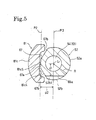
- a cut part 66 is formed between a lower end part 45e1 contiguous with the shaft part 52 of the exhaust cam part 45e, and the shaft part 52 below the lower end part 45e1.
- the cut part 66 has a bottom surface 66a included in a plane P1 (Fig. 4) perpendicular to an axis L2 of swing motion.
- a cut part 67 is formed in the shaft part 52 so as to extend downward from a position overlapping the cut part 66 with respect to the direction of the arrow A parallel to the axis of rotation.
- the cut part 67 has a middle bottom surface 67a included in a plane P2 perpendicular to the plane P1 and parallel to the axis L1 of rotation, and a pair of end bottom surfaces 67b (Fig. 5)inclined to the middle bottom surface 67a and parallel to the axis L1 of rotation.
- the cut part 66 is formed by cutting a part of the lower end part 45e1 of the exhaust cam part 45e and a part near the exhaust cam part 45e of the shaft part 52 such that the distance d1 (Fig. 5)between the axis L1 of rotation of the bottom surface 66a is smaller than the radius R of the cylindrical surface 52a, and the bottom surface 66a is nearer to the axis L1 of rotation than the surface of the shaft part 52.
- the cut part 67 is formed by cutting part of the shaft part 52 such that the distance d2 (Fig.
- a holding part 69 is formed above the cut part 67 in the shaft part 52.
- the holding part 69 has a pair of projections 68a and 68b radially outwardly projecting from the shaft part 52 in parallel to the plane P1.
- the projections 68a and 68b are provided with holes 70, and a cylindrical pin 71 is fitted in the holes 70 of the arms 68a and 68b, and a flyweight 81 is supported by the pin 71 for swing motion relative to the camshaft 15.
- the projections 68a and 68b are spaced a distance apart in the direction of the axis of the pin 71 and are formed integrally with the camshaft 15.
- each decompressing mechanism D includes a decompression member 80 of a metal, such as an iron alloy containing 15% nickel, and a return spring 90.
- the return spring 90 is a torsion coil spring.
- the decompression member 80 has the flyweight 81 supported for turning by the pin 71 on the holding part 69, a decompression cam 82 that swings together with the flyweight 81, comes into contact with the slipper 48b of the exhaust rocker arm 48 in a starting phase of the internal combustion engine E to exert a valve opening force on the exhaust valve 43, and a flat arm 83 connecting the flyweight 81 and the decompression cam 82.
- the decompression member 80 is a molding integrally including the flyweight 81, the decompression cam 82 and the arm 83 is formed by metal injection.
- Metal injection is a forming process including steps of forming a molding of metal powder by injection molding, and sintering the molding.
- the return spring 90 extended between the pair of projections 68a and 68b has one end 90a engaged with the flyweight 81, and the other end 90b (Fig. 7A) engaged with the projection 68a.
- the resilience of the return spring 90 is adjusted so that a torque capable of holding the flyweight 81 at an initial position shown in Fig. 7A while the engine speed is below a predetermined engine speed.
- the flyweight 81 has a weight body 81c, and a pair of flat projections 81a and 81b projecting from the weight body 81c in a direction parallel to the axis L2 of swing motion (hereinafter referred to as "the direction of the arrow B") and lying on the outer side of the projections 68a and 68b, respectively.
- the projections 81a and 81b extend from the weight body 81c toward the pin 71.
- the projections 81a and 81b have a thickness t3, i.e., thickness along the direction of the arrow B as viewed in Fig.
- the projections 81a and 81b are provided with holes 84 of a diameter equal to that of the holes 70.
- the pin 71 is fitted in the holes 70 and 84 so as to be turnable therein.
- the length g2 of the holes 84 along the direction of the arrow B (or the thickness of the projections 81a and 81b) is greater than the length g1 of the holes 70 along the direction of the arrow B (or the thickness of the projections 68a and 68b). Therefore, the sum of the lengths of the holes 84 (or the sum of the thicknesses of the projections 81a and 81b) is greater than the sum of the lengths of the holes 70 (or the sum of the thicknesses of the projections 68a and 68b). Therefore, the area of parts of the surface in contact with the projections 81a and 81b of the pin 71 is greater than that of parts of the surface 71 in contact with the holding part 69. As shown in Fig. 4, both the projections 68a and 68b and both the projections 81a and 81b lie in a range narrower than the outside diameter of the shaft part 52 of the camshaft 15 with respect to the direction of the arrow B.
- the axis L2 of swing motion aligned with the axis of the pin 71 is included in a plane P4 (Fig. 7A and 7B) substantially perpendicular to the axis L1 of rotation of the camshaft 15 and does not intersect the axis L1 of rotation and the bore 54.
- the axis L2 of swing motion is at a distance greater than the radius R of the shaft part 52 from the axis L1 of rotation or the reference plane P3 as shown in Fig. 4. Therefore, the holding part 69 having the projections 68a and 68b is able to set the axis L2 of swing motion at a distance greater than the radius R of the shaft part 52 from the reference plane P3. Consequently, the pin 71 does not intersect the axis L1 of rotation and the bore 54, and is separated diametrically from the axis L1 of rotation and the bore 54.
- the weight body 81c of the flyweight 81 has a thickness t2 along a diametrical direction greater than the thickness t1 of the arm 83 along a diametrical direction.
- the weight body 81c of the flyweight 81 has a thickness t2 in a diametrical direction greater than the thickness t3 of the projections 81a and 81b and the thickness t1 of the arm 83.
- the weight body 81c has a width (Fig. 4) along the direction of the arrow B greater than the thickness t3 of the projections 81a and 81b and the thickness t1 of the arm 83.
- the maximum width of the weight body 81c is approximately equal to the diameter including the heel 45a of the valve-operating cam 45.
- the weight body 81c extends from the joint 81c1 of the flyweight 81 and the arm 83 on the side of the axis L1 of rotation with respect to the arm 83 along the axis L2 of swing motion to a position on the opposite side of the arm 83 with respect to the axis L1 of rotation, and has opposite end parts 81c2 and 81c3 with respect to the axis L2 of swing motion extending nearer to the reference plane P3 than the bottom surface 67a of the cut part 67.
- the outer surface 81c6 of the weight body 81c extends radially inward with distance from the pin 71 toward the direction of the arrow A. In this embodiment, the outer surface 81c6 extends so as to approach radially the shaft part 52 with downward distance.
- the arm 83 having the thickness t1 along the direction of the arrow B is formed in a length such that the decompression cam 82 does not project from the shaft part 52 of the camshaft 15 in a direction perpendicular to the reference plane P3 as viewed in the direction of the arrow B.
- a contact protrusion 81c5 is formed in a flat part 81c4a of the inner surface 81c4 (Fig. 6D), facing the camshaft 15, of the weight body 81c.
- the contact protrusion 81c5 rests on the middle bottom surface 67a of the cut part 67 when the flyweight 81 (or the decompression member 80) is set at the initial position.
- a gap C (Fig. 7A) is formed between the decompression cam 82 and the valve-operating cam 45 with respect to the direction of the arrow A.
- a contact protrusion 83b (Fig. 6A) is formed on the flat lower end surface, i.e.
- the contact protrusion 83b rests on the upper surface 52b1 of a step 52b (Fig. 7A) adjacent to the bottom surface 66a and forming the lower side wall of the cut part 66 to determine a full-expansion position for the radially outward swing motion of the flyweight 81 (or the decompression member 80).
- the contact protrusion 81c5 is in contact with the middle bottom surface 67a (Fig. 5) and the flyweight 81 (or the decompression member 80) stays at the initial position with a part thereof lying in the cut part 67 until the internal combustion engine E is started, the camshaft 15 is rotated, and a torque acting about the axis L2 of swing motion and produced by centrifugal force acting on the decompression member 80 increase beyond an opposite torque produced by the resilience of the return spring 90.
- the flyweight 81 is restrained from swinging by frictional force acting between the decompression cam 82 and the slipper 48b pressed by the resilience of the valve spring 44 against the decompression cam 82 even if the torque produced by the centrifugal force exceeds the opposite torque produced by the resilience of the return spring 90.
- the distance between a flat part 81c4a (Fig. 6B) farthest from the reference plane P3 of the inner surface 81c4 and the reference plane P3 is shorter than the radius R of the cylindrical surface 52a as shown in Fig. 4.
- the center G of gravity (Fig. 7A) of the decompression member 80 is always below the axis L2 of swing motion, i.e., at a position near the reference plane P3, when the decompression member 80 swings in a maximum range of swing motion between the initial position and the full-expansion position, is slightly on the side of the reference plane P3 with respect to a vertical line crossing the axis L2 of swing motion when the decompression member 80 is at the initial position.
- the flyweight 81 approaches the reference plane P3 or the axis L1 of rotation when the flyweight 81 is turned to the full-expansion position. Furthermore, the pin 71 and the weight body 81c are disposed such that the pin 71 and the weight body 81c always overlap each other, as viewed in the direction of the arrow A, in the maximum range of swing motion.
- the decompression cam 82 formed at the extremity of the arm 83 has a cam lobe 82s (Fig. 4) protruding in the direction of the axis L2 of swing motion, and a contact surface 82a on the opposite side of the cam lobe 82s.
- the contact surface 82a is in contact with the bottom surface 66a and slides along the bottom surface 66a when the arm 83 swings together with the flyweight 81.
- the decompression cam 82 When the decompression member 80 is at the initial position, i.e., when the decompression member 80 is in the decompressing operation, the decompression cam 82 is on the opposite side of the axis L2 of swing motion and the flyweight 81 with respect to the reference plane P3, is received in an upper part 66b (Fig. 7A), contiguous with the exhaust cam part, of the cut part 66, does not project from the shaft part 52 of the camshaft 15 in a direction perpendicular to the reference plane P3, as viewed in the direction of the arrow B, and projects radially by a predetermined maximum height H (Figs. 3 and 4) from the heel 45a of included in the base circle of the valve-operating cam 45.
- the predetermined height H defines a decompression lift L D (Fig. 3) by which the exhaust valve 43 is lifted up for decompression.
- the center G of gravity of the decompression member 80 is on the side of the reference plane )3 with respect to the axis L2 of swing motion, and the decompression member 80 is in an initial state where a clockwise torque, as viewed in Fig. 7A, produced by the weight of the decompression member 80 about the axis L2 of swing motion and a counterclockwise torque produced by the resilience of the return spring 90 act on the decompression member 80. Since the resilience of the return spring 90 is determined such that the counterclockwise torque is greater than the clockwise torque, the flyweight 81 (or the decompression member 80) is held at the initial position as shown in Fig. 7A, and the decompression cam 82 is received in the upper part 66b contiguous with the exhaust cam part of the cut part 66.
- the crankshaft 8 is rotated by pulling a starter knob 13a (Fig. 1) connected to a rope wound on a reel included in the rewind starter 13 to start the internal combustion engine E. Then, the camshaft 15 rotates at a rotating speed equal to half the rotating speed of the crankshaft 8.
- the rotating speed of the crankshaft 8, i.e., the engine speed is not higher than the predetermined engine speed in this state, and hence the decompression member 80 is held at the initial position because the torque produced by centrifugal force acting on the decompression member 80 is lower than the torque produced by the resilience of the return spring 90.
- the decompression cam 82 is separated from the slipper 48b of the exhaust rocker arm 48 , the decompression member 80 starts being turned clockwise, as viewed in Fig. 7A, by the torque produced by the centrifugal force, the arm 83 slides along the bottom surface 66a, the decompression member 80 is turned until the same reaches the full-expansion position where the contact protrusion 83b of the arm 83 is in contact with the upper surface 52b1 of the step 52b as shown in Fig. 7B.
- the decompression cam 82 With the decompression member 80 at the full-expansion position, the decompression cam 82 is separated from the upper part 66b contiguous with the exhaust cam part of the cut part 66 in the direction of the arrow A and is separated fro the slipper 48b, so that the decompressing operation is stopped. Consequently, the slipper 48b is in contact with the heel 45a of the exhaust cam part 45e while the cylinder bore 2a is in a compression stroke as indicated by two-dot chain lines in Fig. 3 to compress an air-fuel mixture at a normal compression pressure. Thereafter, the engine speed increases to an idling speed.
- the center G of gravity of the decompression member 80 is at a distance approximately equal to the distance d2 (Fig. 5) between the axis L2 of swing motion and the reference plane P3 from the reference plane P3. Since the outer surface 81c6 of the weight body 81c of the flyweight 81 extends radially inward with distance from the pin 71 downward, the radial expansion of a cylindrical space in which the flyweight 81 revolves is suppressed, and the circumference of the cylindrical space coincides substantially with the cylindrical surface 52a having the shape of a circular cylinder of the shaft part 52.
- the mass ratio of the flyweight 81 to the decompressing mechanism D is large because the flyweight 81 is a block and the decompressing mechanism D is provided with the single arm 83.
- the decompressing mechanism D comprises the component parts respectively having different thicknesses.
- the width of the along the direction of the arrow B of the flyweight 81 is greater than the thickness t1 along the direction of the arrow B of the arm 83 extending along the plane P1, the thickness t2 along the radial direction of the flyweight 81 is greater than the thickness t1 along the direction of the arrow B of the arm 83.
- the flyweight 81 is placed in a space radially extending into the camshaft 15 so that the flyweight 81 overlaps the camshaft 15 as viewed from the direction perpendicular to the reference plane P3, the increase of the size of the decompressing mechanism D can be suppressed and, consequently, the space around the camshaft 15 in which the decompressing mechanism D in the full-expanded position revolves can be narrowed or the increase of the space can be suppressed.
- the width along the direction of the arrow B of the weight body 81c is greater than the thickness t3 of the projections 81a and 81b and the thickness t1 of the arm 83, and the thickness along the radial direction of the weight body 81c is greater than the thickness t3 of the projections 81a and 81b and the thickness t1 of the arm 83. Therefore, the masses of the projections 81a and 81b and the arm 83 is reduced to the least possible extent, maintaining necessary rigidity, to concentrate most part of the mass of the decompressing mechanism d on the weight body 81c.
- the sum of the lengths along the direction of the arrow B of the holes 84 of the projections 81a and 81b is greater than the sum of the lengths along the direction of the arrow B of the holes 70 of the projections 68a and 68b of the camshaft. Therefore, the area of a part, in contact with the projections 81a and 81b, of the pin 71 is large and hence pressure acting on the contact surfaces is reduced, so that the abrasion of the contact parts of the projections 81a and 81b and the pin 71 due to the vibration of the internal combustion engine E is reduced.
- the end part 71b of the pin 71 projecting from the hole 84 of the projection 81a on the outer side of the holding part 69 with respect to the direction of the arrow B is pressed to form an expanded part 73, so that the pin 71 is held in the holes 84 and 70.
- the pin 71 can be held in place simply by press work.
- the arm 83 and the projections 81a and 81b extend individually from the weight body 81c. Therefore, the thicknesses and shapes of the arm 83 and the projections 81a and 81b can be individually determined, and the optimum designing of the positional relation of the flyweight 81 and the arm 83 with the camshaft 15, the projections 81a and 81b, the weight body 81c and the arm 83 is possible.
- the projections 81a and 81b, and the arm 83 can be individually designed, increase in size of the projections 81a and 81b supporting only the weight body 81c can be suppressed as compared with the lever, which corresponds to the decompression member, of the prior art A in which the part supported on the pin supports the flyweight and the arm. This also contributes to the concentration of the most mass on the weight body 81c and to the suppression of the dimensional increase of the flyweight 81, hence the decompression member 80.
- the projections 81a and 81b can be easily formed in the thickness t3 greater than the thickness t1 of the arm 83 regardless of the thickness t1 of the arm 83 to increase the area of contact between the projections 81a and 81b and the pin 71, which is advantageous for reducing the abrasion of the contact parts of the flyweight 81 and the pin 71.
- the axis L2 of swing motion of the flyweight 81 of the decompressing mechanism D is included in a plane P4 substantially perpendicular to the axis L1 of rotation of the camshaft 15, is separate radially from the axis L1 of rotation and, preferably, does not intersect the oil passage 63, i.e., the bore 54. Therefore, the bore 54 can be formed in the camshaft 15 provided with the decompressing mechanism D to reduce the weight of the camshaft 15, the diameter of the bore 54 is scarcely limited by the pin 71 held on the camshaft 15, and the bore 54 can be formed in a comparatively big diameter.
- the bore 54 is able to serve as the oil passage 63 capable of passing the lubricating oil sufficient for lubricating the valve mechanism and the decompressing mechanisms D installed in the valve gear chamber 14. If the camshaft 15 having the bore 54 of a comparatively big diameter is formed by casting, a core for forming the bore 54 having a comparatively big diameter can be formed more easily than a core of a small diameter for forming an oil passage of a comparatively small diameter.
- the flyweight 81 needs to turn only through a small angle to stop the decompressing operation.
- the cylindrical space around the axis L1 of rotation, in which the fully expanded decompressing mechanism D revolves can be radially contracted, a comparatively large space does not need to be secured for the decompressing mechanism D around the camshaft 15 and, consequently, the internal combustion engine E can be formed in a comparatively small size. Since the pin 71 and the weight body 81c always overlap each other as viewed from the direction of the arrow A in the maximum range of swing motion, the cylindrical space around the camshaft 15 necessary for the fully expanded decompressing mechanism D to revolve can be contracted.
- the position of the center of gravity of the flyweight 81 and hence the center G of gravity of the decompression member 80 can be easily spaced far from the reference plane P3. Since the distance between the position of the center G of gravity of the decomposition member 80 and the axis L1 of rotation is thus increased, the weight of the flyweight 81 for generating a necessary centrifugal force can be reduced accordingly, the internal combustion engine E can be formed in lightweight construction, and the radial expansion of the cylindrical space necessary for the revolution of the fully expanded decompression member 80 and the decompressing mechanisms D can be suppressed.
- the decompressing mechanism D can be formed in a small size.
- the distance between the axis L2 of swing motion and the decompression cam 82 is longer than that when the axis L2 of swing motion is on the shaft part 52 of the camshaft 15, which enables the reduction of the maximum angle of swing motion and contributes to the radial reduction of the cylindrical space necessary for the fully expanded decompression member 80 to revolve.
- the axis L2 of swing motion is radially spaced from the axis L1 of rotation and the bore 54, the decompression member 80 is provided integrally with the flyweight 81, the decompression cam 82 and the arm 83, the weight body 81c of the flyweight 81 and the arm 83 have different thicknesses, respectively, and the weight body 81c is a block of a thickness greater than that of the arm 83.
- the concentration of the mass on the weight body 81c of the flyweight 81 is promoted, increase in size of the decompression member 80 can be suppressed, the mass of the flyweight 81 is sufficient for stopping the decompressing operation, the center of gravity of the flyweight 81 can be easily set at a position far from the reference plane P3, and the radial expansion of the cylindrical space necessary for the fully expanded decompression member 80 to revolve can be suppressed.
- the load placed on the arm 83 by the exhaust rocker arm 48 during the decompressing operation can be reduced. Therefore, the thickness t1 of the arm 83 may be small, and the arm 83 can be formed in a small weight.
- the enlargement of the weight body 81c in a radial direction can be suppressed, the weight body 81c can be extended along the axis L2 of swing motion to a position on the opposite side of the arm 83 with respect to the axis L1 of rotation, and the opposite end parts 81c2 and 81c3 can be extended nearer to the reference plane P3 than the middle bottom surface 67a of the cut part 67, which further facilitates the concentration of the mass on the flyweight 81 of the decompression member 80.
- the flyweight 81, the decompression cam 82 and the arm 83 have different thicknesses, respectively, the flyweight 81, the decompression cam 82 and the arm 83 can be integrally formed in a high dimensional accuracy by metal injection. Therefore, the difference in operating characteristic between the decompressing mechanisms D is small, and the decompressing mechanisms D capable of stably exercising the operating characteristic can be easily manufactured.
- the cut part 67 capable of receiving the flyweight 81 therein is formed near the axis L1 of rotation in the camshaft 15, the cylindrical space for the revolution of the fully expanded decompressing mechanism D extends around the axis L1 of rotation of the camshaft 15, a comparatively large space does not need to be secured around the camshaft 15 for the decompressing mechanism D, and the internal combustion engine E can be formed in a small size.
- the decompressing mechanism D has the contact protrusion 815c that comes into contact with the camshaft 15 to define the initial position of the flyweight 81 received in the cut part 67, and the return spring 90 for applying a resilient force to the flyweight 81 to press the flyweight 81 toward the initial position, the flyweight 81 is received in the cut part 67 near the axis L1 of rotation.
- the flyweight 81 can be held at the initial position with the contact protrusion 81c5 in contact with the camshaft 15 by the resilience of the return spring 90, can be held stably without being affected by gravity at the initial position, and generation of noise due to collision between the flyweight 81 and the camshaft 15 caused by vibrations can be suppressed regardless of the positional relation of the initial position of the flyweight 81 with the axis L2 of swing motion while the camshaft 15 is stopped and while the internal combustion engine E is operating at engine speeds in an engine speed range for the decompressing operation.
- a decompressing mechanism in a modification of the decompressing mechanism D in the foregoing embodiment will be described. Only parts of the decompressing mechanism in the modification different from those of the decompressing mechanism D in the foregoing embodiment will be described.
- the pin 71 is inserted slidably in the holes 70 of the holding part 69.
- the pin 71 may be slidably inserted in the holes 84 and may be fixedly pressed in the holes 70, and the flyweight 81 (or the decompression member 80) may be swingably supported on the pin 71.
- the flyweight 81 can be pivotally supported by the pin 71 on the camshaft 15 provided with the bore 54, and most part of strain developed in the camshaft 15 by the combination of the pin 71 with the camshaft 15 by press fitting can be absorbed by the holding part 69 including the projections 68a and 68b projecting radially outward from the camshaft by pressing the pin 71 supporting the flyweight 81 in the holding part 69 including the projections 68a and 68b projecting radially outward from the camshaft 15.
- the decompression member 80 of the decompressing mechanism D of the foregoing embodiment is a single member integrally including functional parts
- the decompressing mechanism D may include individual members including a flyweight, a decompression cam and an arm, at least one of those members may be a different member, and the flyweight, the decompression cam and the arm may be joined together by fixing means.
- the holding part 69 may include a single projection instead of the pair of projections 68a and 68b.
- the decompression member 80 integrally including the component parts may be formed by any suitable forming means other than metal injection.
- the intake valve 42 and the exhaust valve 43 are operated for opening and closing by the single, common valve-operating cam 45 in the foregoing embodiment, the intake valve 42 and the exhaust valve 43 may be controlled by a valve-operating cam specially for operating the intake valve 42 and a valve-operating cam specially for operating the exhaust valve 43, respectively.
- the intake valve 42 may be operated by the decompressing mechanism D instead of the exhaust valve 43.
- the center G of gravity of the decompression member 80 is nearer to the reference plane P3 than the axis L2 of swing motion and the decompression member 80 is held at the initial position by the return spring 90 in the foregoing embodiment, the center G of gravity of the decompression member 80 may be farther from reference plane P3 than the axis L2 of swing motion, the decompression member 80 may be held at the initial position by a torque produced by its own weight, and the return spring 90 may be omitted.
- the projections 81a and 81b of the flyweight 81 are on the outer side of the holding part 69 of the camshaft 15 with respect to the direction of the arrow B in the foregoing embodiment, the projections 81a and 81b of the flyweight 81 may be on the inner side of the holding part 69 of the camshaft 15 with respect to the direction of the arrow B.
- the expanded part 73 is formed by pressing the end part 71b, projecting from the hole 70 of the holding part 69, of the pin 71, and the flyweight 81 may be provided with a single projection instead of the two projections 81a and 81b.
- camshaft 15 is provided with the oil passage 63 in the foregoing embodiment, a hollow camshaft having a bore 54 not serving as an oil passage may be used.
- the present invention is applicable also to a horizontal internal combustion engine having a crankshaft having a horizontal axis of rotation.
- the present invention is applicable not only to the internal combustion engine for the outboard motor, but also for general-purpose internal combustion engines for driving generators, compressors, pumps and such, and those for vehicles.
- the present invention is applicable to single-cylinder internal combustion engines and multiple cylinder internal combustion engines provided with three or more cylinders.
- the internal combustion engine in the foregoing embodiment is a spark-ignition engine
- the internal combustion engine may be a compression-ignition engine.
- the starting device may be any suitable starting device other than the rewind starter, such as a kick starter, a manual starter or a starter motor.
- the axis L2 of swing motion is at a distance greater than the radius R of the shaft part 52 from the reference plane P3 in the foregoing embodiment, the distance may be shorter than the radius R.
- the camshaft 15 is provided with the bore 54 in the foregoing embodiment, the cam shaft 15 need not necessarily be provided with the bore 54.
- the pin 71 may be held on the camshaft 15 so that the axis L2 of swing motion is perpendicular to the axis L1 of rotation whether or not the camshaft 15 is provided with the bore 54.
- the reference plane P3 includes both the axis L1 of rotation and the axis L2 of swing motion.
- the arm 83 is connected to the weight body 81c of the flyweight in the foregoing embodiment, the arm 83 may be connected to either the projection 81a or the projection 81b.
Landscapes
- Engineering & Computer Science (AREA)
- Mechanical Engineering (AREA)
- General Engineering & Computer Science (AREA)
- Chemical & Material Sciences (AREA)
- Combustion & Propulsion (AREA)
- Ocean & Marine Engineering (AREA)
- Valve Device For Special Equipments (AREA)
- Valve-Gear Or Valve Arrangements (AREA)
Abstract

Description
- The present invention relates to an internal combustion engine provided with a centrifugal decompressing means for reducing compression pressure to facilitate staring the internal combustion engine by opening a valve included in the internal combustion engine during the compression stroke in starting the internal combustion engine.
- Internal combustion engines provided with a centrifugal decompressing means including a flyweight are disclosed in JP2000-227064A and JP11-294130A. The decompressing means of those known techniques, which will be referred to as "prior art A", includes a lever provided with a weight and a decompression cam, and having the shape of a flat plate of a substantially uniform thickness. The lever is supported for turning at two parts thereof diametrically facing a camshaft by a pin on the camshaft. The decompression cam is connected to the weight by two arms extending from the two parts of the lever supported by the pin.
- Centrifugal decompressing means of techniques disclosed in JP63-246406A and U.S. Pat. No. 3,395,689, which will be referred to as "prior art B", includes a lever provided with a weight and a decompression cam, and having the shape of a flat plate of a substantially uniform thickness. The lever is supported for turning at one part thereof by a pin on a camshaft. Therefore, the decompression cam is connected to the weight by a single arm extending from the one part of the lever supported by the pin. The weight capable of swinging on the pin relative to the camshaft overlaps the camshaft as viewed from a direction perpendicular to a plane including the axis of rotation of the camshaft and parallel to the axis of swing motion or a to a plane including the axis of rotation of the camshaft and a plane including the axis of swing motion.
- According to the prior art A, the lever, which corresponds to a decompression member, has the two arms and hence the mass ratio of the weight to the lever is low. Therefore, it is difficult to concentrate a large part of the mass of the lever on the weight to generate a high centrifugal force necessary for stopping a decompressing operation at a set engine speed without increasing the weight of the lever. To generate a necessary centrifugal force, the size of the lever increases and the diameter of a cylindrical space in which the fully expanded lever revolves around the camshaft increases, the layout of members in a valve gear chamber in which the camshaft is disposed is subject to restrictions, and the weight of the lever increases.
- According to the prior art B, the lever corresponding to a decompression member is provided with the single arm. Therefore, the mass ratio of the weight to the lever of the decompressing means of the prior art B is greater than that of the weight to the lever of the decompressing means of the prior art A. However, since the thickness of the weight is equal to that of the arm, i.e., the thickness of a plate forming the lever, it is difficult to concentrate mass on the weight simultaneously with the reduction of the size of the decompressing means.
- The lever needs to be bent or an additional member needs to be attached to the lever to concentrate mass on the weight included integrally with the lever formed from a plate of a uniform thickness. Thus, the concentration of mass on the weight increases working steps, and requires difficult work because the lever has a complicated shape. Consequently, the respective operating characteristics of such complicated levers, i.e., decompression members, are distributed in a wide range.
- The present invention has been made in view of such circumstances and it is therefore an object of the present invention to provide an internal combustion engine provided with a small, lightweight decompressing means including a flyweight on which most part of the mass of the decompressing means can be concentrated. Another object of the present invention is to provide a simple method of preventing a pin from coming off, to cancel the connection of the projection of a flyweight and an arm, and to optimize the designs of the component parts of a decompressing means. A third object of the present invention is to facilitate the manufacture of decompressing means respectively having operating characteristics distributed in a narrow range.
- According to the present invention, an internal combustion engine comprises a crankshaft, a camshaft driven for rotation in synchronism with the crankshaft, a valve-operating cam formed on the camshaft, engine valves operated for opening and closing by the valve-operating cam, and a decompressing means for opening the engine valve in a compression stroke in a starting phase, wherein the decompressing means comprises a flyweight supported for swing motion by a pin on the camshaft, a decompression cam that operates together with the flyweight to exert a valve-opening force on the engine valve, and an arm connecting the flyweight and the decompression cam, the flyweight has a weight body and projections projecting from the weight body and engaged with the pin, the pin is disposed such that the axis of swing motion of the flyweight is included in a plane substantially perpendicular to the axis of rotation of the camshaft, the weight body is a block of width along the axis of swing motion and a thickness along a radial direction which are greater than the thickness along the axis of swing motion of the arm, and the weight body overlaps the camshaft as viewed from a direction perpendicular to a reference plane including the axis of rotation of the camshaft and parallel to the axis of swing motion.
- In the decompressing means including the flyweight having the weight body and the projections engaged with the pin, and the arm, the mass ratio of the weight body to the decompressing means is large. The weight body is formed in the width along the axis of swing motion greater than the thickness of the arm, and in the thickness in the radial direction greater than the thickness of the arm to form the decompressing means of component parts respectively having different thicknesses. Therefore, the flyweight has a necessary rigidity, the mass of the arm can be reduced to the least possible extent, most part of the mass of the decompressing means is concentrated on the weight body, and the weight body is disposed in a space radially inside the camshaft such that the weight body overlaps the camshaft as viewed from the direction perpendicular to the reference plane.
- The decompressing means thus formed has the following effects. Since the decompressing means includes the flyweight having the weight body and the projections, and the arm, and the weight body has the width and the thickness which are greater than the thickness of the arm, the decompressing means is lightweight and most part of the mass of the decompressing means can be concentrated on the weight body. The weight body overlapping the camshaft as viewed form the direction perpendicular to the reference plane suppresses the enlargement of the decompressing means, and therefore the fully expanded decompressing means is able to revolve around the camshaft in a small cylindrical space around the camshaft or the expansion of the cylindrical space can be suppressed.
- The arm may have the shape of a plate, and the thickness of the arm may be equal to the thickness of a plate forming the arm. The arm may be extended from the flyweight in a plane perpendicular to the axis of swing motion.
- Preferably, camshaft has a holding part including projections provided with first holes, respectively, the projections of the flyweight are provided with second holes, respectively, the pin is inserted in the first holes so as to be turnable therein and is inserted in the second holes to support the flyweight for turning, an end part projecting outside from the first or the second hole is pressed to form an expanded part for preventing the pin from coming off the first and the second holes.
- Thus, the following effect is produced. The pin can be prevented from coming off the first and the second holes simply by pressing the end part thereof.
- The arm may be extended from the weight body. Since the projections through which the pin is inserted, and the arm connecting the flyweight and the decompression cam can be thus extended in different directions, respectively, from the weight body, the thicknesses and the shapes of the projections and the arm can be individually determined, and the optimum designing of the positional relation of the flyweight and the arm with the camshaft, the projections, the weight body and the arm is possible.
- The flyweight, the decompression cam and the arm can be formed integrally in a single structure by metal injection.
- Although the decompressing means is formed by integrally combining the component parts respectively having different thicknesses, the flyweight, the decompression cam and the arm can be formed in high dimensional accuracy. Since the flyweight, the decompression cam and the arm respectively having different thicknesses are formed integrally in high dimensional accuracy, the decompressing means has an operating characteristic in a narrow range around a reference operating characteristic, and the decompressing means capable of exhibiting stable operating characteristic can be easily manufactured.
- According to one aspect of the present invention, the crankshaft has a vertical axis of rotation, a cut part for receiving the flyweight therein is formed in the outer surface of the camshaft, and the decompressing means includes a return spring that exerts resilient force on the flyweight received in the cut part to hold the flyweight at an initial position.
- A second cut for receiving the arm connecting the flyweight and the decompression cam, and the decompression cam therein may be formed in the outer surface of the camshaft, and the arm may be provided with a contact protrusion that rests on the camshaft to locate the flyweight at a full-expansion position.
- The second cut part may be provided with a step with which the arm comes into contact. Desirably, the second cut part has a bottom surface along which the arm slides when the flyweight swings.
- In this specification, the expression, 'substantially perpendicular' is used for expressing both an exactly perpendicularly intersecting condition and an approximately perpendicularly intersecting condition. Terms, 'diametrical direction' and 'circumferential direction' signify a direction parallel to a diameter of the camshaft and a direction along the outer surface of the camshaft, respectively, unless otherwise specified.
- In the drawings:
- Fig. 1 is a schematic side elevation of an outboard motor including an internal combustion engine provided with a decompressing mechanism in a preferred embodiment according to the present invention, as viewed from the right-hand side of the outboard motor;
- Fig. 2 is a longitudinal sectional view of a part, around a cylinder head, of the internal combustion shown in Fig. 1;
- Fig. 3 is a sectional view taken on line III-III in Fig. 2, corresponding to a sectional view in a plane including the axes of an intake valve and an exhaust valve with the cylinder head and to a sectional view similar to Fig. 4 with a camshaft;
- Fig. 4 is a sectional view taken on line IV-IV in Fig. 7A;
- Fig. 5 is a sectional view taken on line V-V in Fig. 7A;
- Fig. 6A is a side elevation of a decompression member included in the decompressing mechanism shown in Fig. 1;
- Fig. 6B is a view take in the direction of the arrow B in Fig. 6A;
- Fig. 6C is a view take in the direction of the arrow C in Fig. 6A;
- Fig. 6D is a view take in the direction of the arrow D in Fig. 6A;
- Fig. 7A is a view of the decompressing mechanism at an initial position;
- Fig. 7B is a view of the decompressing mechanism at a full-expansion position.
-
- An internal combustion engine provided with decompressing mechanisms in a preferred embodiment of the present invention will be described with reference to the accompanying drawings.
- Referring to Fig. 1, an internal combustion engine E provided with decompressing mechanisms D according to the present invention is a water-cooled, inline, two-cylinder, four-stroke-cycle, vertical internal combustion engine installed in an outboard motor with the axis of rotation of its
crankshaft 8 vertically extended. The internal combustion engine E comprises acylinder block 2 provided with twocylinder bores 2a in a vertical, parallel arrangement with their axes longitudinally horizontally extended, acrankcase 3 joined to the front end of thecylinder block 2; acylinder head 4 joined to the rear end of thecylinder block 2; and a cylinder head cover joined to the rear end of thecylinder head 4. Thecylinder block 2, thecrankcase 3, thecylinder head 4 and thecylinder head cover 5 constitute an engine body. - A
piston 6 is fitted for reciprocating sliding motions in each of the cylinder bores 2a and is connected to acrankshaft 8 by a connecting rod 7. Thecrankshaft 8 is installed in a crank chamber 9 and is supported for rotation in upper and lower plain bearings on thecylinder block 2 and thecrankcase 3. Thecrankshaft 8 is driven for rotation by thepistons 6 driven by combustion pressure produced by the combustion of an air-fuel mixture ignited by spark plugs. - The phase difference between the
pistons 6 fitted in the twocylinder bores 2a corresponds to a crank angle of 360°. Therefore, combustion occurs alternately in the cylinder bores 2a at equal angular intervals in this internal combustion engine E. A crankshaft pulley 11 and a rewind starter 13 are mounted in that order on an upper end part of thecrankshaft 8 projecting upward from the crank changer 9. - Referring to Figs. 1 and 2, a
camshaft 15 is installed in avalve gear chamber 14 defined by thecylinder head 4 and thecylinder head cover 5 and is supported for rotation on thecylinder head 4 with its axis L1 of rotation extended in parallel with that of thecrankshaft 8. Acamshaft pulley 16 is mounted on anupper end part 15a of thecamshaft 15 projecting upward from thevalve gear chamber 14. Thecamshaft 15 is driven for rotation in synchronism with thecrankshaft 8 at a rotating speed equal to half that of thecrankshaft 8 by thecrankshaft 8 through a transmission mechanism including the crankshaft pulley 11, thecamshaft pulley 16 and atiming belt 17 extended between thepulleys 11 and 16. Alower end part 15b of thecamshaft 15 is coupled by ashaft coupling 19 with apump drive shaft 18a connected to theinner rotor 18b of atrochoid oil pump 18 attached to the lower end wall of thecylinder head 4. - As shown in Fig. 1, the engine body is joined to the upper end of a
support block 20. Anextension case 21 has an upper end joined to the lower end of thesupport block 20 and a lower end joined to agear case 22. An undercover 23 joined to the upper end of theextension case 21 covers a lower half part of the engine body and thesupport block 20. Anengine cover 24 joined to the upper end of theunder cover 23 covers an upper half part of the engine body. - A
drive shaft 25 connected to a lower end part of thecrankshaft 8 extends downward through thesupport block 20 and theextension case 21, and is connected to apropeller shaft 27 by a propelling direction switching device 26 including a bevel gear mechanism and a clutch mechanism. The power of the internal combustion engine e is transmitted through thecrankshaft 8, thedrive shaft 25, a propelling direction switching device 26 and thepropeller shaft 27 to apropeller 28 fixedly mounted on a rear end part of thepropeller shaft 27 to drive thepropeller 28 for rotation. - The
outboard motor 1 is detachably connected to ahull 30 by atransom clamp 31. Aswing arm 33 is supported for swing motions in a vertical plane by atilt shaft 32 on thetransom clamp 31. Atubular swivel case 34 is connected to the rear end of theswing arm 33. Aswivel shaft 35 fitted for rotation in theswivel case 34 has an upper end part provided with a mountingframe 36 and a lower end part provided with acenter housing 37. The mountingframe 36 is connected elastically through arubber mount 38a to thesupport block 20. Thecenter housing 37 is connected elastically through arubber mount 38b to theextension case 21. A steering arm, not shown, is connected to the front end of the mountingframe 36. The steering arm is turned in a horizontal plane for controlling the direction of theoutboard motor 1. - Further description of the internal combustion engine E will be made with reference to Figs. 2 and 3. An intake port 40 through which an air-fuel mixture prepared by a carburetor, not shown, flows into a
combustion chamber 10 and anexhaust port 41 through which combustion gases discharged from thecombustion chamber 10 flows are formed for each of the cylinder bores 2a in thecylinder head 4. Anintake valve 42 that opens and closes the intake port 40 and anexhaust valve 43 that opens and closes theexhaust port 41 are urged always in a closing direction by the resilience of valve springs 44. Theintake valve 42 and theexhaust valve 43 are operated for opening and closing operations by a valve train installed in thevalve gear chamber 14. The valve train includes thecamshaft 15, valve-operating cams 45 formed on thecamshaft 15 so as to correspond to the cylinder bores 2a, intake rocker arms (cam followers) 47 mounted for rocking motion on arocker shaft 46 fixedly supported on thecylinder head 4 and driven by the valve-operating cams 45, and exhaust rocker arms (cam followers) 48 mounted on therocker shaft 46 and driven by the valve-operating cams 45. - Each valve-
operating cam 45 has anintake cam part 45i, anexhaust cam part 45e, and acam surface 45s common to theintake cam part 45i and theexhaust cam part 45e. Theintake rocker arm 47 has one end part provided with an adjustingscrew 47a in contact with theintake valve 42 and the other end provided with a slipper 47b in contact with thecam surface 45s of theintake cam part 45i of the valve-operating cam 45. Theexhaust rocker arm 48 has one end provided with an adjustingscrew 48a in contact with theexhaust valve 43 and the other end provided with aslipper 48b in contact with thecam surface 45s of theexhaust cam part 45e of the valve-operating cam 45. Thecam surface 45s of the valve-operating cam 45 has aheel 45a of a shape conforming to a base circle for keeping theintake valve 42 and theexhaust valve 43 closed, and atoe 45b that times the operation of theintake valve 42 and theexhaust valve 43 and determines the lift of theintake valve 42 and theexhaust valve 43. The valve-operating cams 45 rotate together with thecamshaft 15 to rock theintake rocker arms 47 and theexhaust rocker arms 48 to operate theintake valves 42 and theexhaust valves 43. - As shown in Fig. 2, the
camshaft 15 has the pair of valve-operating cams 45, anupper journal 50a, alower journal 50b, an upper thrust-bearingpart 51a continuous with theupper journal 50a, a lower thrust-bearingpart 51b continuous with thelower journal 50b,shaft parts 52 extending between the valve-operating cams 45 and between the valve-operating cam 45 and the lower thrust-bearingpart 51b, and a pump-drivingcam 53 for driving a fuel pump, not shown. Thecamshaft 15 has acentral bore 54 having an open lower end opening in the end surface of thelower end part 15b in which thelower journal 50b is formed, and a closed upper end in theupper journal 50a. Thebore 54 extends vertically in the direction of the arrow A parallel with the axis of rotation of thecamshaft 15. - The
upper journal 50a is supported for rotation in anupper bearing 55a held in the upper wall of thecylinder head 4, and alower journal 55b is supported for rotation in alower bearing 55b held in the lower wall of thecylinder head 4. Eachshaft part 52 has acylindrical surface 52a having the shape of a circular cylinder of a radius R smaller than the radius of theheel 45a of a shape conforming to the base circle. The pump-drivingcam 53 is formed on theshaft part 52. The pump-drivingcam 53 drives adrive arm 56 supported for swinging on therocker shaft 46 for swing motion to reciprocate the drive rod included in the fuel pump in contact with thedrive arm 56. - A lubricating system will be described. Referring to Fig. 1, an
oil pan 57 is formed in thesupport block 20. A lower end provided with anoil strainer 58 of asuction pipe 59 is immersed in a lubricating oil contained in theoil pan 57. Thesuction pipe 59 has an upper end connected by a joint to anoil passage 60a formed in thecylinder block 2. Theoil passage 60a communicates with thesuction port 18e (Fig. 2) of theoil pump 18 by means of anoil passage 60b formed in thecylinder head 4. - The discharge port, not shown, of the
oil pump 18 is connected through oil passages, not shown, formed in thecylinder head 4 and thecylinder block 2, and an oil filter, not shown, to a main oil passage, not shown, formed in thecylinder block 2. A plurality of branch oil passages branch from the main oil passage. The branch oil passages are connected to the bearings and sliding parts including the plain bearings supporting thecrankshaft 8 of the internal combustion engine E. Onebranch oil passage 61 among the plurality of branch oil passages is formed in thecylinder head 4 to supply the lubricating oil to the sliding parts of the valve train and the decompressing mechanisms D in thevalve gear chamber 14 as shown in Fig. 2. - The
oil pump 18 sucks the lubricating oil into a pump chamber 81d formed between aninner rotor 18b and anouter rotor 18c through theoil strainer 58, thesuction pipe 59, theoil passages oil pan 57. The high-pressure lubricating oil discharged from thepump chamber 18d flows through the discharge port, the oil filter, the main oil passage and the plurality of branch passages including thebranch passage 61 to the sliding parts. - Part of the lubricating oil flowing through the
oil passage 61 opening into the bearing surface of theupper bearing 55a flows through anoil passage 62 formed in theupper journal 50a and opening into thebore 54. Theoil passage 62 communicates intermittently with theoil passage 61 once every one turn of thecamshaft 15 to supply the lubricating oil into thebore 54. Thebore 54 serves as anoil passage 63. The lubricating oil supplied into theoil passage 63 flows throughoil passages 64 opening in the cam surfaces 45s of the valve-operating cams 45 to lubricate the sliding surfaces of theslippers 47a of theintake rocker arms 47 and the valve-operating cams 45 and to lubricate the sliding surfaces of theslippers 48b of theexhaust rocker arms 48 and the valve-operating cams 45. The rest of the lubricating oil flowing through theoil passage 63 flows out of theoil passage 63 through anopening 54a to lubricate the sliding parts of thelower bearing 55b and thelower journal 50b, and the sliding parts of the lower Thrust-bearingpart 51b and thelower bearing 55b, and flows into thevalve gear chamber 14. Theoil passages 64 does not need to be formed necessarily in parts shown in Fig. 2; theoil passages 64 may be formed, for example, in parts opposite to thetoes 45b of the valve-operating cams 45 across the axis L1 of rotation. - The rest of the lubricating oil flowing through the
oil passage 61 flows through a small gap between theupper journal 50a and theupper bearing 55a to lubricate the sliding parts of the Thrust-bearingpart 51a and theupper bearing 55a, flows into thevalve gear chamber 14. The lubricating oil flowed through theoil passages valve gear chamber 14 lubricates the sliding parts of theintake rocker arms 47, theexhaust rocker arms 48, the drive arm, and therocker shaft 46. Eventually, the lubricating oil flowing through theoil passage 61 drops or flows down to the bottom of thevalve gear chamber 14, and flows through return passages, not shown, formed in thecylinder head 4 and thecylinder block 2 to theoil pan 57. - As shown in Figs. 2 and 3, the decompressing mechanisms D, which perform a decompressing operation to reduce force necessary for operating the rewind starter 13 in starting the internal combustion engine E, are combined with the
camshaft 15. The decompressing mechanisms D correspond to the cylinder bores 2a, respectively. The decompressing mechanisms D perform a decompressing operation to reduce force necessary for operating the rewind starter 13 in starting the internal combustion engine E. Each decompressing mechanism D causes the corresponding cylinder bore 2a to discharge the gas contained therein in a compression stroke through theexhaust port 41 to decompress thecylinder bore 2a. The decompressing mechanisms D are identical and the difference in phase between the decompressing mechanisms D is equal to a cam angle of 180° corresponding to a crank angle of 360°. - Referring to Figs. 4, 5 and 7A, each decompressing mechanism D is formed on the
shaft part 52 contiguous with theexhaust cam part 45e in contact with theslipper 48b of theexhaust rocker arm 48 of the valve-operating cam 45. As shown in Fig. 7A, acut part 66 is formed between a lower end part 45e1 contiguous with theshaft part 52 of theexhaust cam part 45e, and theshaft part 52 below the lower end part 45e1. Thecut part 66 has abottom surface 66a included in a plane P1 (Fig. 4) perpendicular to an axis L2 of swing motion. Acut part 67 is formed in theshaft part 52 so as to extend downward from a position overlapping thecut part 66 with respect to the direction of the arrow A parallel to the axis of rotation. Thecut part 67 has amiddle bottom surface 67a included in a plane P2 perpendicular to the plane P1 and parallel to the axis L1 of rotation, and a pair of end bottom surfaces 67b (Fig. 5)inclined to themiddle bottom surface 67a and parallel to the axis L1 of rotation. - More concretely, the
cut part 66 is formed by cutting a part of the lower end part 45e1 of theexhaust cam part 45e and a part near theexhaust cam part 45e of theshaft part 52 such that the distance d1 (Fig. 5)between the axis L1 of rotation of thebottom surface 66a is smaller than the radius R of thecylindrical surface 52a, and thebottom surface 66a is nearer to the axis L1 of rotation than the surface of theshaft part 52. Thecut part 67 is formed by cutting part of theshaft part 52 such that the distance d2 (Fig. 5) between thebottom surface 67a and a reference plane P3 including the axis L1 of rotation and parallel to the axis L2 of swing motion is smaller than the radius R of thecylindrical surface 52a, and thebottom surface 67a is nearer to the axis L1 of rotation than the surface of theshaft part 52. - As shown in Fig. 4, a holding
part 69 is formed above thecut part 67 in theshaft part 52. The holdingpart 69 has a pair ofprojections shaft part 52 in parallel to the plane P1. Theprojections holes 70, and acylindrical pin 71 is fitted in theholes 70 of thearms flyweight 81 is supported by thepin 71 for swing motion relative to thecamshaft 15. Theprojections pin 71 and are formed integrally with thecamshaft 15. - Referring to Figs. 6A to 6C, each decompressing mechanism D includes a
decompression member 80 of a metal, such as an iron alloy containing 15% nickel, and areturn spring 90. Thereturn spring 90 is a torsion coil spring. Thedecompression member 80 has theflyweight 81 supported for turning by thepin 71 on the holdingpart 69, adecompression cam 82 that swings together with theflyweight 81, comes into contact with theslipper 48b of theexhaust rocker arm 48 in a starting phase of the internal combustion engine E to exert a valve opening force on theexhaust valve 43, and aflat arm 83 connecting theflyweight 81 and thedecompression cam 82. Thedecompression member 80 is a molding integrally including theflyweight 81, thedecompression cam 82 and thearm 83 is formed by metal injection. Metal injection is a forming process including steps of forming a molding of metal powder by injection molding, and sintering the molding. - The
return spring 90 extended between the pair ofprojections end 90a engaged with theflyweight 81, and the other end 90b (Fig. 7A) engaged with theprojection 68a. The resilience of thereturn spring 90 is adjusted so that a torque capable of holding theflyweight 81 at an initial position shown in Fig. 7A while the engine speed is below a predetermined engine speed. - The
flyweight 81 has aweight body 81c, and a pair offlat projections weight body 81c in a direction parallel to the axis L2 of swing motion (hereinafter referred to as "the direction of the arrow B") and lying on the outer side of theprojections projections weight body 81c toward thepin 71. Theprojections arm 83 and smaller than the thickness t2 of theweight body 81c of theflyweight 81 shown in Fig. 6B by way of example. Theprojections holes 84 of a diameter equal to that of theholes 70. Thepin 71 is fitted in theholes - The length g2 of the
holes 84 along the direction of the arrow B (or the thickness of theprojections holes 70 along the direction of the arrow B (or the thickness of theprojections projections projections projections pin 71 is greater than that of parts of thesurface 71 in contact with the holdingpart 69. As shown in Fig. 4, both theprojections projections shaft part 52 of thecamshaft 15 with respect to the direction of the arrow B. - Thus, in supporting the
flyweight 81 on thecamshaft 15, holes 84 of theprojections holes 70 of theprojections return spring 90 are aligned, and then thepin 71 provided with ahead 71a is inserted from the side of theprojection 81b in theholes return spring 90. Anend part 71b of thepin 71 projecting from theother projection 81a, i.e., anend part 71b extending outside thehole 84 of theprojection 81a, is pressed to form an expandedpart 73, so that thepin 71 is held in theholes decompression member 80 including theflyweight 81 is supported for swing motion on thecamshaft 15. When thedecompression member 80 swings, thepin 71 turns together with thedecompression member 80 in theholes 70 of the holdingpart 69. - The axis L2 of swing motion aligned with the axis of the
pin 71 is included in a plane P4 (Fig. 7A and 7B) substantially perpendicular to the axis L1 of rotation of thecamshaft 15 and does not intersect the axis L1 of rotation and thebore 54. In this embodiment, the axis L2 of swing motion is at a distance greater than the radius R of theshaft part 52 from the axis L1 of rotation or the reference plane P3 as shown in Fig. 4. Therefore, the holdingpart 69 having theprojections shaft part 52 from the reference plane P3. Consequently, thepin 71 does not intersect the axis L1 of rotation and thebore 54, and is separated diametrically from the axis L1 of rotation and thebore 54. - As best shown in Figs. 4 and 6, the
weight body 81c of theflyweight 81 has a thickness t2 along a diametrical direction greater than the thickness t1 of thearm 83 along a diametrical direction. Theweight body 81c of theflyweight 81 has a thickness t2 in a diametrical direction greater than the thickness t3 of theprojections arm 83. Theweight body 81c has a width (Fig. 4) along the direction of the arrow B greater than the thickness t3 of theprojections arm 83. The maximum width of theweight body 81c is approximately equal to the diameter including theheel 45a of the valve-operating cam 45. - The
weight body 81c extends from the joint 81c1 of theflyweight 81 and thearm 83 on the side of the axis L1 of rotation with respect to thearm 83 along the axis L2 of swing motion to a position on the opposite side of thearm 83 with respect to the axis L1 of rotation, and has opposite end parts 81c2 and 81c3 with respect to the axis L2 of swing motion extending nearer to the reference plane P3 than thebottom surface 67a of thecut part 67. When thedecompression member 80 is at the initial position, the outer surface 81c6 of theweight body 81c extends radially inward with distance from thepin 71 toward the direction of the arrow A. In this embodiment, the outer surface 81c6 extends so as to approach radially theshaft part 52 with downward distance. - The
arm 83 projecting from theweight body 81c in a direction different from a direction in which theprojections cut part 66 when thedecompression member 80 is at the initial position, and extends along thebottom surface 66a on the side of one end part 81c2 of theweight body 81c. Thearm 83 having the thickness t1 along the direction of the arrow B is formed in a length such that thedecompression cam 82 does not project from theshaft part 52 of thecamshaft 15 in a direction perpendicular to the reference plane P3 as viewed in the direction of the arrow B. - Referring to Figs. 7A and 7B, a contact protrusion 81c5 is formed in a flat part 81c4a of the inner surface 81c4 (Fig. 6D), facing the
camshaft 15, of theweight body 81c. The contact protrusion 81c5 rests on themiddle bottom surface 67a of thecut part 67 when the flyweight 81 (or the decompression member 80) is set at the initial position. When thedecompression member 80 is at the initial position, a gap C (Fig. 7A) is formed between thedecompression cam 82 and the valve-operating cam 45 with respect to the direction of the arrow A. Acontact protrusion 83b (Fig. 6A) is formed on the flat lower end surface, i.e. , a side surface along the direction of the arrow A, of thearm 83. Thecontact protrusion 83b rests on the upper surface 52b1 of astep 52b (Fig. 7A) adjacent to thebottom surface 66a and forming the lower side wall of thecut part 66 to determine a full-expansion position for the radially outward swing motion of the flyweight 81 (or the decompression member 80). - In an initial state where the
decompression cam 82 is separated from theslipper 48b and thecamshaft 15 is stopped, the contact protrusion 81c5 is in contact with themiddle bottom surface 67a (Fig. 5) and the flyweight 81 (or the decompression member 80) stays at the initial position with a part thereof lying in thecut part 67 until the internal combustion engine E is started, thecamshaft 15 is rotated, and a torque acting about the axis L2 of swing motion and produced by centrifugal force acting on thedecompression member 80 increase beyond an opposite torque produced by the resilience of thereturn spring 90. When theslipper 48b is in contact with thedecompression cam 82, theflyweight 81 is restrained from swinging by frictional force acting between thedecompression cam 82 and theslipper 48b pressed by the resilience of thevalve spring 44 against thedecompression cam 82 even if the torque produced by the centrifugal force exceeds the opposite torque produced by the resilience of thereturn spring 90. - When the
decompression member 80 is at the initial position, the distance between a flat part 81c4a (Fig. 6B) farthest from the reference plane P3 of the inner surface 81c4 and the reference plane P3 is shorter than the radius R of thecylindrical surface 52a as shown in Fig. 4. The center G of gravity (Fig. 7A) of thedecompression member 80 is always below the axis L2 of swing motion, i.e., at a position near the reference plane P3, when thedecompression member 80 swings in a maximum range of swing motion between the initial position and the full-expansion position, is slightly on the side of the reference plane P3 with respect to a vertical line crossing the axis L2 of swing motion when thedecompression member 80 is at the initial position. Thus, theflyweight 81 approaches the reference plane P3 or the axis L1 of rotation when theflyweight 81 is turned to the full-expansion position. Furthermore, thepin 71 and theweight body 81c are disposed such that thepin 71 and theweight body 81c always overlap each other, as viewed in the direction of the arrow A, in the maximum range of swing motion. - The
decompression cam 82 formed at the extremity of thearm 83 has acam lobe 82s (Fig. 4) protruding in the direction of the axis L2 of swing motion, and acontact surface 82a on the opposite side of thecam lobe 82s. Thecontact surface 82a is in contact with thebottom surface 66a and slides along thebottom surface 66a when thearm 83 swings together with theflyweight 81. When thedecompression member 80 is at the initial position, i.e., when thedecompression member 80 is in the decompressing operation, thedecompression cam 82 is on the opposite side of the axis L2 of swing motion and theflyweight 81 with respect to the reference plane P3, is received in anupper part 66b (Fig. 7A), contiguous with the exhaust cam part, of thecut part 66, does not project from theshaft part 52 of thecamshaft 15 in a direction perpendicular to the reference plane P3, as viewed in the direction of the arrow B, and projects radially by a predetermined maximum height H (Figs. 3 and 4) from theheel 45a of included in the base circle of the valve-operating cam 45. The predetermined height H defines a decompression lift LD (Fig. 3) by which theexhaust valve 43 is lifted up for decompression. - While the
decompression cam 82 is in contact with theslipper 48b of theexhaust rocker arm 48 to open theexhaust valve 43, load placed by the resilience of thevalve spring 44 on through theexhaust rocker arm 48 on thedecompression cam 82 is born by thebottom surface 66a. Consequently, load that is exerted on thearm 83 by theexhaust rocker arm 48 during the decompressing operation is reduced and hence the thickness t1 of thearm 83 may be small. - The operation and effect of the embodiment will be described.
- While the internal combustion engine E is stopped and the
camshaft 15 is not rotating, the center G of gravity of thedecompression member 80 is on the side of the reference plane )3 with respect to the axis L2 of swing motion, and thedecompression member 80 is in an initial state where a clockwise torque, as viewed in Fig. 7A, produced by the weight of thedecompression member 80 about the axis L2 of swing motion and a counterclockwise torque produced by the resilience of thereturn spring 90 act on thedecompression member 80. Since the resilience of thereturn spring 90 is determined such that the counterclockwise torque is greater than the clockwise torque, the flyweight 81 (or the decompression member 80) is held at the initial position as shown in Fig. 7A, and thedecompression cam 82 is received in theupper part 66b contiguous with the exhaust cam part of thecut part 66. - The
crankshaft 8 is rotated by pulling astarter knob 13a (Fig. 1) connected to a rope wound on a reel included in the rewind starter 13 to start the internal combustion engine E. Then, thecamshaft 15 rotates at a rotating speed equal to half the rotating speed of thecrankshaft 8. The rotating speed of thecrankshaft 8, i.e., the engine speed, is not higher than the predetermined engine speed in this state, and hence thedecompression member 80 is held at the initial position because the torque produced by centrifugal force acting on thedecompression member 80 is lower than the torque produced by the resilience of thereturn spring 90. When eachcylinder bore 2a is in a compression stroke, thedecompression cam 82 radially projecting from theheel 45a of the valve-operating cam 45 comes into contact with theslipper 48b to turn theexhaust rocker arm 48 such that theexhaust valve 43 is lifted up by the predetermined decompression lift LD. Consequently, the air-fuel mixture compressed in thecylinder bore 2a is discharged through theexhaust port 41, so that the pressure in the cylinder bore 2a decreases, thepiston 6 is made easily to pass the top dead center, and hence the rewind starter 13 can be operated by a low force. - After the engine speed has exceeded the predetermined engine speed, the torque produced by the centrifugal force acting on the
decompression member 80 exceeds the torque produced by the resilience of thereturn spring 90. If thedecompression cam 82 is separated from theslipper 48b of theexhaust rocker arm 48 , thedecompression member 80 starts being turned clockwise, as viewed in Fig. 7A, by the torque produced by the centrifugal force, thearm 83 slides along thebottom surface 66a, thedecompression member 80 is turned until the same reaches the full-expansion position where thecontact protrusion 83b of thearm 83 is in contact with the upper surface 52b1 of thestep 52b as shown in Fig. 7B. With thedecompression member 80 at the full-expansion position, thedecompression cam 82 is separated from theupper part 66b contiguous with the exhaust cam part of thecut part 66 in the direction of the arrow A and is separated fro theslipper 48b, so that the decompressing operation is stopped. Consequently, theslipper 48b is in contact with theheel 45a of theexhaust cam part 45e while thecylinder bore 2a is in a compression stroke as indicated by two-dot chain lines in Fig. 3 to compress an air-fuel mixture at a normal compression pressure. Thereafter, the engine speed increases to an idling speed. With thedecompression member 80 at the full-expanded position, the center G of gravity of thedecompression member 80 is at a distance approximately equal to the distance d2 (Fig. 5) between the axis L2 of swing motion and the reference plane P3 from the reference plane P3. Since the outer surface 81c6 of theweight body 81c of theflyweight 81 extends radially inward with distance from thepin 71 downward, the radial expansion of a cylindrical space in which theflyweight 81 revolves is suppressed, and the circumference of the cylindrical space coincides substantially with thecylindrical surface 52a having the shape of a circular cylinder of theshaft part 52. - Thus, the mass ratio of the
flyweight 81 to the decompressing mechanism D is large because theflyweight 81 is a block and the decompressing mechanism D is provided with thesingle arm 83. The decompressing mechanism D comprises the component parts respectively having different thicknesses. The width of the along the direction of the arrow B of theflyweight 81 is greater than the thickness t1 along the direction of the arrow B of thearm 83 extending along the plane P1, the thickness t2 along the radial direction of theflyweight 81 is greater than the thickness t1 along the direction of the arrow B of thearm 83. Thus, most part of the mass can be concentrated on theflyweight 81, while the decompressing mechanism D can be formed in a lightweight structure. Since theflyweight 81 is placed in a space radially extending into thecamshaft 15 so that theflyweight 81 overlaps thecamshaft 15 as viewed from the direction perpendicular to the reference plane P3, the increase of the size of the decompressing mechanism D can be suppressed and, consequently, the space around thecamshaft 15 in which the decompressing mechanism D in the full-expanded position revolves can be narrowed or the increase of the space can be suppressed. - The width along the direction of the arrow B of the
weight body 81c is greater than the thickness t3 of theprojections arm 83, and the thickness along the radial direction of theweight body 81c is greater than the thickness t3 of theprojections arm 83. Therefore, the masses of theprojections arm 83 is reduced to the least possible extent, maintaining necessary rigidity, to concentrate most part of the mass of the decompressing mechanism d on theweight body 81c. - The sum of the lengths along the direction of the arrow B of the
holes 84 of theprojections holes 70 of theprojections projections pin 71 is large and hence pressure acting on the contact surfaces is reduced, so that the abrasion of the contact parts of theprojections pin 71 due to the vibration of the internal combustion engine E is reduced. - The
end part 71b of thepin 71 projecting from thehole 84 of theprojection 81a on the outer side of the holdingpart 69 with respect to the direction of the arrow B is pressed to form an expandedpart 73, so that thepin 71 is held in theholes pin 71 can be held in place simply by press work. - The
arm 83 and theprojections weight body 81c. Therefore, the thicknesses and shapes of thearm 83 and theprojections flyweight 81 and thearm 83 with thecamshaft 15, theprojections weight body 81c and thearm 83 is possible. For example, since theprojections arm 83 can be individually designed, increase in size of theprojections weight body 81c can be suppressed as compared with the lever, which corresponds to the decompression member, of the prior art A in which the part supported on the pin supports the flyweight and the arm. This also contributes to the concentration of the most mass on theweight body 81c and to the suppression of the dimensional increase of theflyweight 81, hence thedecompression member 80. Theprojections arm 83 regardless of the thickness t1 of thearm 83 to increase the area of contact between theprojections pin 71, which is advantageous for reducing the abrasion of the contact parts of theflyweight 81 and thepin 71. - The axis L2 of swing motion of the
flyweight 81 of the decompressing mechanism D is included in a plane P4 substantially perpendicular to the axis L1 of rotation of thecamshaft 15, is separate radially from the axis L1 of rotation and, preferably, does not intersect theoil passage 63, i.e., thebore 54. Therefore, thebore 54 can be formed in thecamshaft 15 provided with the decompressing mechanism D to reduce the weight of thecamshaft 15, the diameter of thebore 54 is scarcely limited by thepin 71 held on thecamshaft 15, and thebore 54 can be formed in a comparatively big diameter. Consequently, thebore 54 is able to serve as theoil passage 63 capable of passing the lubricating oil sufficient for lubricating the valve mechanism and the decompressing mechanisms D installed in thevalve gear chamber 14. If thecamshaft 15 having thebore 54 of a comparatively big diameter is formed by casting, a core for forming thebore 54 having a comparatively big diameter can be formed more easily than a core of a small diameter for forming an oil passage of a comparatively small diameter. - Since the axis L2 of swing motion is separated radially from the axis L1 of rotation and the
bore 54 so that thearm 83 extends beyond the axis L1 of rotation as viewed form the direction of the arrow B, i.e., thepin 71 and thedecompression cam 82 are on the opposite sides of the reference plane P3, the distance between the axis L2 of swing motion and thedecompression cam 82 is longer as compared with that when the axis L2 of swing motion intersects the axis L1 of rotation substantially perpendicularly. Therefore, theflyweight 81 needs to turn only through a small angle to stop the decompressing operation. Since the maximum swing angle of theflyweight 81 is small, the cylindrical space around the axis L1 of rotation, in which the fully expanded decompressing mechanism D revolves, can be radially contracted, a comparatively large space does not need to be secured for the decompressing mechanism D around thecamshaft 15 and, consequently, the internal combustion engine E can be formed in a comparatively small size. Since thepin 71 and theweight body 81c always overlap each other as viewed from the direction of the arrow A in the maximum range of swing motion, the cylindrical space around thecamshaft 15 necessary for the fully expanded decompressing mechanism D to revolve can be contracted. - Since the axis L2 of swing motion is spaced radially from the axis L1 of rotation, the position of the center of gravity of the
flyweight 81 and hence the center G of gravity of thedecompression member 80 can be easily spaced far from the reference plane P3. Since the distance between the position of the center G of gravity of thedecomposition member 80 and the axis L1 of rotation is thus increased, the weight of theflyweight 81 for generating a necessary centrifugal force can be reduced accordingly, the internal combustion engine E can be formed in lightweight construction, and the radial expansion of the cylindrical space necessary for the revolution of the fully expandeddecompression member 80 and the decompressing mechanisms D can be suppressed. Since thearm 83 can be formed in a length such that thearm 83 does not project from theshaft part 52 of thecamshaft 15 in a direction perpendicular to the reference plane P3 as viewed from the direction of the arrow B in the maximum range of swing motion, the decompressing mechanism D can be formed in a small size. - Since the
single pin 71 pivotally supporting theflyweight 81 is held by the holdingpart 69 having theprojections camshaft 15, the distance between the axis L2 of swing motion and thedecompression cam 82 is longer than that when the axis L2 of swing motion is on theshaft part 52 of thecamshaft 15, which enables the reduction of the maximum angle of swing motion and contributes to the radial reduction of the cylindrical space necessary for the fully expandeddecompression member 80 to revolve. - The axis L2 of swing motion is radially spaced from the axis L1 of rotation and the
bore 54, thedecompression member 80 is provided integrally with theflyweight 81, thedecompression cam 82 and thearm 83, theweight body 81c of theflyweight 81 and thearm 83 have different thicknesses, respectively, and theweight body 81c is a block of a thickness greater than that of thearm 83. Thus, the concentration of the mass on theweight body 81c of theflyweight 81 is promoted, increase in size of thedecompression member 80 can be suppressed, the mass of theflyweight 81 is sufficient for stopping the decompressing operation, the center of gravity of theflyweight 81 can be easily set at a position far from the reference plane P3, and the radial expansion of the cylindrical space necessary for the fully expandeddecompression member 80 to revolve can be suppressed. - Load produced by the resilience of the
valve spring 44 and placed through theexhaust rocker arm 48 on thedecompression cam 82 is born by thebottom surface 66a. Thus, the load placed on thearm 83 by theexhaust rocker arm 48 during the decompressing operation can be reduced. Therefore, the thickness t1 of thearm 83 may be small, and thearm 83 can be formed in a small weight. Since the axis L2 of swing motion does not intersect the axis L1 of rotation and thebore 54, and theflyweight 81 is received in thecut part 67, the enlargement of theweight body 81c in a radial direction can be suppressed, theweight body 81c can be extended along the axis L2 of swing motion to a position on the opposite side of thearm 83 with respect to the axis L1 of rotation, and the opposite end parts 81c2 and 81c3 can be extended nearer to the reference plane P3 than themiddle bottom surface 67a of thecut part 67, which further facilitates the concentration of the mass on theflyweight 81 of thedecompression member 80. - Although the
flyweight 81, thedecompression cam 82 and thearm 83 have different thicknesses, respectively, theflyweight 81, thedecompression cam 82 and thearm 83 can be integrally formed in a high dimensional accuracy by metal injection. Therefore, the difference in operating characteristic between the decompressing mechanisms D is small, and the decompressing mechanisms D capable of stably exercising the operating characteristic can be easily manufactured. - Since the
cut part 67 capable of receiving theflyweight 81 therein is formed near the axis L1 of rotation in thecamshaft 15, the cylindrical space for the revolution of the fully expanded decompressing mechanism D extends around the axis L1 of rotation of thecamshaft 15, a comparatively large space does not need to be secured around thecamshaft 15 for the decompressing mechanism D, and the internal combustion engine E can be formed in a small size. Moreover, since the decompressing mechanism D has the contact protrusion 815c that comes into contact with thecamshaft 15 to define the initial position of theflyweight 81 received in thecut part 67, and thereturn spring 90 for applying a resilient force to theflyweight 81 to press theflyweight 81 toward the initial position, theflyweight 81 is received in thecut part 67 near the axis L1 of rotation. Therefore, theflyweight 81 can be held at the initial position with the contact protrusion 81c5 in contact with thecamshaft 15 by the resilience of thereturn spring 90, can be held stably without being affected by gravity at the initial position, and generation of noise due to collision between theflyweight 81 and thecamshaft 15 caused by vibrations can be suppressed regardless of the positional relation of the initial position of theflyweight 81 with the axis L2 of swing motion while thecamshaft 15 is stopped and while the internal combustion engine E is operating at engine speeds in an engine speed range for the decompressing operation. - A decompressing mechanism in a modification of the decompressing mechanism D in the foregoing embodiment will be described. Only parts of the decompressing mechanism in the modification different from those of the decompressing mechanism D in the foregoing embodiment will be described.
- In the foregoing embodiment, the
pin 71 is inserted slidably in theholes 70 of the holdingpart 69. Thepin 71 may be slidably inserted in theholes 84 and may be fixedly pressed in theholes 70, and the flyweight 81 (or the decompression member 80) may be swingably supported on thepin 71. Theflyweight 81 can be pivotally supported by thepin 71 on thecamshaft 15 provided with thebore 54, and most part of strain developed in thecamshaft 15 by the combination of thepin 71 with thecamshaft 15 by press fitting can be absorbed by the holdingpart 69 including theprojections pin 71 supporting theflyweight 81 in the holdingpart 69 including theprojections camshaft 15. Consequently, the deformation of thecamshaft 15 and that of thecam surface 45s of the valve-operating cam can be suppressed, the abrasion of the sliding parts of thecamshaft 15 and the valve-operating cam 45 attributable to such deformations can be reduced, and the durability of thecamshaft 15 and the valve-operating cam 45 can be improved. - Although the
decompression member 80 of the decompressing mechanism D of the foregoing embodiment is a single member integrally including functional parts, the decompressing mechanism D may include individual members including a flyweight, a decompression cam and an arm, at least one of those members may be a different member, and the flyweight, the decompression cam and the arm may be joined together by fixing means. The holdingpart 69 may include a single projection instead of the pair ofprojections decompression member 80 integrally including the component parts may be formed by any suitable forming means other than metal injection. - Although the
intake valve 42 and theexhaust valve 43 are operated for opening and closing by the single, common valve-operating cam 45 in the foregoing embodiment, theintake valve 42 and theexhaust valve 43 may be controlled by a valve-operating cam specially for operating theintake valve 42 and a valve-operating cam specially for operating theexhaust valve 43, respectively. Theintake valve 42 may be operated by the decompressing mechanism D instead of theexhaust valve 43. - Although the center G of gravity of the
decompression member 80 is nearer to the reference plane P3 than the axis L2 of swing motion and thedecompression member 80 is held at the initial position by thereturn spring 90 in the foregoing embodiment, the center G of gravity of thedecompression member 80 may be farther from reference plane P3 than the axis L2 of swing motion, thedecompression member 80 may be held at the initial position by a torque produced by its own weight, and thereturn spring 90 may be omitted. - Although the
projections flyweight 81 are on the outer side of the holdingpart 69 of thecamshaft 15 with respect to the direction of the arrow B in the foregoing embodiment, theprojections flyweight 81 may be on the inner side of the holdingpart 69 of thecamshaft 15 with respect to the direction of the arrow B. If theprojections flyweight 81 are on the inner side of the holdingpart 69 of thecamshaft 15 with respect to the direction of the arrow B, the expandedpart 73 is formed by pressing theend part 71b, projecting from thehole 70 of the holdingpart 69, of thepin 71, and theflyweight 81 may be provided with a single projection instead of the twoprojections - Although the
camshaft 15 is provided with theoil passage 63 in the foregoing embodiment, a hollow camshaft having abore 54 not serving as an oil passage may be used. The present invention is applicable also to a horizontal internal combustion engine having a crankshaft having a horizontal axis of rotation. The present invention is applicable not only to the internal combustion engine for the outboard motor, but also for general-purpose internal combustion engines for driving generators, compressors, pumps and such, and those for vehicles. The present invention is applicable to single-cylinder internal combustion engines and multiple cylinder internal combustion engines provided with three or more cylinders. - Although the internal combustion engine in the foregoing embodiment is a spark-ignition engine, the internal combustion engine may be a compression-ignition engine. The starting device may be any suitable starting device other than the rewind starter, such as a kick starter, a manual starter or a starter motor.
- Although the axis L2 of swing motion is at a distance greater than the radius R of the
shaft part 52 from the reference plane P3 in the foregoing embodiment, the distance may be shorter than the radius R. - Although the
camshaft 15 is provided with thebore 54 in the foregoing embodiment, thecam shaft 15 need not necessarily be provided with thebore 54. Thepin 71 may be held on thecamshaft 15 so that the axis L2 of swing motion is perpendicular to the axis L1 of rotation whether or not thecamshaft 15 is provided with thebore 54. In such a case, the reference plane P3 includes both the axis L1 of rotation and the axis L2 of swing motion. Although thearm 83 is connected to theweight body 81c of the flyweight in the foregoing embodiment, thearm 83 may be connected to either theprojection 81a or theprojection 81b.
Claims (10)
- An internal combustion engine comprising: a crankshaft (8); a camshaft (15) driven for rotation in synchronism with the crankshaft; a valve-operating cam (45) formed on the camshaft; engine valves (42, 43) operated for opening and closing by the valve-operating cam; and a decompressing means (D) for opening the engine valve in a compression stroke in a starting phase;
characterized in that the decompressing means (D) comprises a flyweight (81) supported for swing motion by a pin (71) on the camshaft (15), a decompression cam (82) that operates together with the flyweight (81) to exert a valve-opening force on the engine valve (42, 43), and an arm (83) connecting the flyweight (81) and the decompression cam (82), the flyweight (81) has a weight body (81c) and projections (81a, 81b) projecting from the weight body (81c) and engaged with the pin (71), the pin (71) is disposed such that an axis (L2) of swing motion of the flyweight (81) is included in a plane (P4) substantially perpendicular to an axis (L1) of rotation of the camshaft (15), the weight body (81c) is a block of a width along the axis (L2) of swing motion and a thickness (t2) along a radial direction which are greater than a thickness (t1) along the axis (L2) of swing motion of the arm (83), and the weight body (81c) overlaps the camshaft (15) as viewed from a direction perpendicular to a reference plane (P3) including the axis (L1) of rotation of the camshaft (15) and parallel to the axis(L2) of swing motion. - The internal combustion engine according to claim 1, characterized in that the arm has the shape of a plate, and the thickness (t1) of the arm is equal to a thickness of a plate.
- The internal combustion engine according to claim 1, characterized in that the arm (83) is extended from the flyweight (81) in a plane (P1) perpendicular to the axis (L2) of swing motion.
- The internal combustion engine according to claim 1, characterized in that the camshaft (15) has a holding part (69) provided with first holes (70), the projections (81a, 81b) of the flyweight (81) are provided with second holes (84), respectively, the pin (71) is inserted in the first holes (70) so as to be turnable therein and is inserted in the second holes (84) to support the flyweight (81) for turning, an end part projecting outside from the first hole (70) or the second hole (84) is pressed to form an expanded part (73) to prevent the pin (71) from coming off the first holes (70) and the second holes (84).
- The internal combustion engine according to claim 1, characterized in that the arm (83) is extended from the weight body (81c).
- The internal combustion engine according to claim 1, characterized in that the flyweight (81), the decompression cam (82) and the arm (83) are formed integrally in a single structure by metal injection.
- The internal combustion engine according to claim 1, characterized in that the crankshaft (8) has a vertical axis of rotation, a cut part (67) for receiving the flyweight (81) therein is formed in an outer surface of the camshaft (15), and the decompressing means (D) includes a return spring (90) that exerts resilient force on the flyweight (81) received in the cut part (67) to hold the flyweight (81) at an initial position.
- The internal combustion engine according to claim 7, characterized in that a second cut (66) for receiving the arm (83) connecting the flyweight (81) and the decompression cam (82), and the decompression cam (82) therein is formed in the outer surface of the camshaft (15), and the arm has a contact protrusion (83b) that rests on the camshaft (15) to locate the flyweight (81) at a full-expansion position.
- The internal combustion engine according to claim 8, characterized in that the second cut part (66) has a step (52b) with which the contact protrusion (83b) comes into contact.
- The internal combustion engine according to claim 8, characterized in that the second cut part (66) has a bottom surface (66a) along which the arm (83) slides when the flyweight (81) swings.
Applications Claiming Priority (4)
| Application Number | Priority Date | Filing Date | Title |
|---|---|---|---|
| JP2002029878 | 2002-02-06 | ||
| JP2002029878A JP4042955B2 (en) | 2002-02-06 | 2002-02-06 | Internal combustion engine having decompression means |
| JP2002105702A JP4059697B2 (en) | 2002-04-08 | 2002-04-08 | Internal combustion engine having decompression means |
| JP2002105702 | 2002-04-08 |
Publications (3)
| Publication Number | Publication Date |
|---|---|
| EP1335115A2 true EP1335115A2 (en) | 2003-08-13 |
| EP1335115A3 EP1335115A3 (en) | 2003-10-22 |
| EP1335115B1 EP1335115B1 (en) | 2005-06-01 |
Family
ID=27615740
Family Applications (1)
| Application Number | Title | Priority Date | Filing Date |
|---|---|---|---|
| EP03250607A Expired - Lifetime EP1335115B1 (en) | 2002-02-06 | 2003-01-31 | Internal combustion engine provided with decompressing means |
Country Status (6)
| Country | Link |
|---|---|
| US (1) | US6857408B2 (en) |
| EP (1) | EP1335115B1 (en) |
| CN (1) | CN100363598C (en) |
| AU (1) | AU2003200190B2 (en) |
| CA (1) | CA2418342C (en) |
| DE (1) | DE60300722T2 (en) |
Families Citing this family (9)
| Publication number | Priority date | Publication date | Assignee | Title |
|---|---|---|---|---|
| JP2003301704A (en) * | 2002-04-08 | 2003-10-24 | Honda Motor Co Ltd | Internal combustion engine provided with decompressing means |
| US6988478B2 (en) * | 2003-04-09 | 2006-01-24 | Aisan Kogyo Kabushiki Kaisha | Resin intake manifold |
| DE10352003A1 (en) * | 2003-11-07 | 2005-06-09 | Robert Bosch Gmbh | Valve for controlling fluids with multifunctional component |
| CN101131111B (en) * | 2007-09-21 | 2010-06-02 | 隆鑫工业有限公司 | Pressure reducing device of water-cooled engine |
| DE102011006288A1 (en) * | 2011-03-29 | 2012-10-04 | Robert Bosch Gmbh | Method for starting internal combustion engine in motor system of hybrid drive system without using starter, involves igniting air/fuel mixture in cylinder of internal combustion engine based on request to perform start operation of engine |
| JP5888200B2 (en) * | 2012-10-01 | 2016-03-16 | 株式会社デンソー | Engine starter |
| CN104564213A (en) * | 2014-12-24 | 2015-04-29 | 重庆宏军汽车配件有限公司 | Pressure reducing valve for high-power gasoline engine |
| CN114248908B (en) * | 2021-12-30 | 2023-06-16 | 广东汇天航空航天科技有限公司 | Propeller and flight equipment |
| CN117450415B (en) * | 2023-12-25 | 2024-03-05 | 山东康达精密机械制造有限公司 | Speed regulator for fuel injection pump of diesel engine |
Citations (6)
| Publication number | Priority date | Publication date | Assignee | Title |
|---|---|---|---|---|
| US3395689A (en) * | 1966-09-15 | 1968-08-06 | Studebaker Corp | Engine decompression apparatus |
| US4453507A (en) * | 1981-11-25 | 1984-06-12 | Briggs & Stratton Corporation | Centrifugally responsive compression release mechanism |
| EP0515183A1 (en) * | 1991-05-21 | 1992-11-25 | Briggs & Stratton Corporation | Improved centrifugally responsive compression release mechanism |
| US5687683A (en) * | 1995-11-22 | 1997-11-18 | Dr. Ing. H.C.F. Porsche Ag | Automatic decompressor for valve-controlled internal combustion engines |
| US5957101A (en) * | 1997-07-09 | 1999-09-28 | Kohler Co. | Automatic compression release mechanism for an internal combustion engine |
| US20010023673A1 (en) * | 2000-01-12 | 2001-09-27 | Hiroyuki Suzuki | Valve cam mechanism for four-cycle engine |
Family Cites Families (5)
| Publication number | Priority date | Publication date | Assignee | Title |
|---|---|---|---|---|
| US3314408A (en) * | 1965-05-17 | 1967-04-18 | Kohler Co | Centrifugally operated compression release mechanism |
| JPS63246404A (en) | 1987-04-01 | 1988-10-13 | Yamaha Motor Co Ltd | Pressure reducing device for internal combustion engine |
| JP3366198B2 (en) * | 1996-11-29 | 2003-01-14 | 本田技研工業株式会社 | Engine decompression mechanism |
| JPH11294130A (en) | 1998-04-07 | 1999-10-26 | Suzuki Motor Corp | Decompressor device of 4-cycle engine |
| JP2000227064A (en) | 1999-02-04 | 2000-08-15 | Sanshin Ind Co Ltd | Decompressor of outboard engine |
-
2003
- 2003-01-22 AU AU2003200190A patent/AU2003200190B2/en not_active Ceased
- 2003-01-29 CN CNB031020771A patent/CN100363598C/en not_active Expired - Fee Related
- 2003-01-31 EP EP03250607A patent/EP1335115B1/en not_active Expired - Lifetime
- 2003-01-31 DE DE60300722T patent/DE60300722T2/en not_active Expired - Lifetime
- 2003-02-04 US US10/357,830 patent/US6857408B2/en not_active Expired - Lifetime
- 2003-02-04 CA CA002418342A patent/CA2418342C/en not_active Expired - Fee Related
Patent Citations (6)
| Publication number | Priority date | Publication date | Assignee | Title |
|---|---|---|---|---|
| US3395689A (en) * | 1966-09-15 | 1968-08-06 | Studebaker Corp | Engine decompression apparatus |
| US4453507A (en) * | 1981-11-25 | 1984-06-12 | Briggs & Stratton Corporation | Centrifugally responsive compression release mechanism |
| EP0515183A1 (en) * | 1991-05-21 | 1992-11-25 | Briggs & Stratton Corporation | Improved centrifugally responsive compression release mechanism |
| US5687683A (en) * | 1995-11-22 | 1997-11-18 | Dr. Ing. H.C.F. Porsche Ag | Automatic decompressor for valve-controlled internal combustion engines |
| US5957101A (en) * | 1997-07-09 | 1999-09-28 | Kohler Co. | Automatic compression release mechanism for an internal combustion engine |
| US20010023673A1 (en) * | 2000-01-12 | 2001-09-27 | Hiroyuki Suzuki | Valve cam mechanism for four-cycle engine |
Also Published As
| Publication number | Publication date |
|---|---|
| CA2418342C (en) | 2008-07-08 |
| DE60300722T2 (en) | 2005-10-27 |
| CN1436922A (en) | 2003-08-20 |
| DE60300722D1 (en) | 2005-07-07 |
| EP1335115A3 (en) | 2003-10-22 |
| EP1335115B1 (en) | 2005-06-01 |
| CN100363598C (en) | 2008-01-23 |
| CA2418342A1 (en) | 2003-08-06 |
| AU2003200190B2 (en) | 2008-06-26 |
| US20030145819A1 (en) | 2003-08-07 |
| US6857408B2 (en) | 2005-02-22 |
| AU2003200190A1 (en) | 2003-08-21 |
Similar Documents
| Publication | Publication Date | Title |
|---|---|---|
| CA2418335C (en) | Internal combustion engine provided with decompressing means and method of adjusting valve lift for decompression | |
| JP4229867B2 (en) | Power unit including an internal combustion engine including a variable compression ratio mechanism | |
| EP1347160A2 (en) | Engine with variable compression ratio | |
| JP4466361B2 (en) | Internal combustion engine | |
| EP1335115B1 (en) | Internal combustion engine provided with decompressing means | |
| US6796294B2 (en) | Internal combustion engine | |
| EP1439286B1 (en) | Internal combustion engine with decompression device | |
| CA2424495C (en) | Internal combustion engine provided with decompressing mechanisms | |
| JP4042955B2 (en) | Internal combustion engine having decompression means | |
| JP4059697B2 (en) | Internal combustion engine having decompression means | |
| JP4083026B2 (en) | Internal combustion engine | |
| JP3998483B2 (en) | Method for adjusting decompression amount of internal combustion engine having decompression means | |
| JP4059776B2 (en) | Internal combustion engine | |
| JP4063682B2 (en) | Multi-cylinder internal combustion engine | |
| JP4063681B2 (en) | Internal combustion engine | |
| JP2001182550A (en) | Engine structure | |
| JP2005133801A (en) | Balancer shaft | |
| JPH05306603A (en) | Lubricating device of valve gear for four cycle engine |
Legal Events
| Date | Code | Title | Description |
|---|---|---|---|
| PUAI | Public reference made under article 153(3) epc to a published international application that has entered the european phase |
Free format text: ORIGINAL CODE: 0009012 |
|
| AK | Designated contracting states |
Designated state(s): AT BE BG CH CY CZ DE DK EE ES FI FR GB GR HU IE IT LI LU MC NL PT SE SI SK TR |
|
| AX | Request for extension of the european patent |
Extension state: AL LT LV MK RO |
|
| PUAL | Search report despatched |
Free format text: ORIGINAL CODE: 0009013 |
|
| AK | Designated contracting states |
Kind code of ref document: A3 Designated state(s): AT BE BG CH CY CZ DE DK EE ES FI FR GB GR HU IE IT LI LU MC NL PT SE SI SK TR |
|
| AX | Request for extension of the european patent |
Extension state: AL LT LV MK RO |
|
| 17P | Request for examination filed |
Effective date: 20040415 |
|
| 17Q | First examination report despatched |
Effective date: 20040525 |
|
| AKX | Designation fees paid |
Designated state(s): DE FR GB SE |
|
| GRAP | Despatch of communication of intention to grant a patent |
Free format text: ORIGINAL CODE: EPIDOSNIGR1 |
|
| GRAS | Grant fee paid |
Free format text: ORIGINAL CODE: EPIDOSNIGR3 |
|
| GRAA | (expected) grant |
Free format text: ORIGINAL CODE: 0009210 |
|
| AK | Designated contracting states |
Kind code of ref document: B1 Designated state(s): DE FR GB SE |
|
| REG | Reference to a national code |
Ref country code: GB Ref legal event code: FG4D |
|
| REF | Corresponds to: |
Ref document number: 60300722 Country of ref document: DE Date of ref document: 20050707 Kind code of ref document: P |
|
| REG | Reference to a national code |
Ref country code: SE Ref legal event code: TRGR |
|
| ET | Fr: translation filed | ||
| PLBE | No opposition filed within time limit |
Free format text: ORIGINAL CODE: 0009261 |
|
| STAA | Information on the status of an ep patent application or granted ep patent |
Free format text: STATUS: NO OPPOSITION FILED WITHIN TIME LIMIT |
|
| 26N | No opposition filed |
Effective date: 20060302 |
|
| REG | Reference to a national code |
Ref country code: DE Ref legal event code: R082 Ref document number: 60300722 Country of ref document: DE Representative=s name: HASELTINE LAKE LLP, DE |
|
| PGFP | Annual fee paid to national office [announced via postgrant information from national office to epo] |
Ref country code: SE Payment date: 20150113 Year of fee payment: 13 |
|
| REG | Reference to a national code |
Ref country code: FR Ref legal event code: PLFP Year of fee payment: 14 |
|
| PGFP | Annual fee paid to national office [announced via postgrant information from national office to epo] |
Ref country code: FR Payment date: 20151208 Year of fee payment: 14 |
|
| PGFP | Annual fee paid to national office [announced via postgrant information from national office to epo] |
Ref country code: DE Payment date: 20160127 Year of fee payment: 14 |
|
| PGFP | Annual fee paid to national office [announced via postgrant information from national office to epo] |
Ref country code: GB Payment date: 20160127 Year of fee payment: 14 |
|
| REG | Reference to a national code |
Ref country code: SE Ref legal event code: EUG |
|
| PG25 | Lapsed in a contracting state [announced via postgrant information from national office to epo] |
Ref country code: SE Free format text: LAPSE BECAUSE OF NON-PAYMENT OF DUE FEES Effective date: 20160201 |
|
| REG | Reference to a national code |
Ref country code: DE Ref legal event code: R119 Ref document number: 60300722 Country of ref document: DE |
|
| GBPC | Gb: european patent ceased through non-payment of renewal fee |
Effective date: 20170131 |
|
| REG | Reference to a national code |
Ref country code: FR Ref legal event code: ST Effective date: 20170929 |
|
| PG25 | Lapsed in a contracting state [announced via postgrant information from national office to epo] |
Ref country code: FR Free format text: LAPSE BECAUSE OF NON-PAYMENT OF DUE FEES Effective date: 20170131 |
|
| PG25 | Lapsed in a contracting state [announced via postgrant information from national office to epo] |
Ref country code: GB Free format text: LAPSE BECAUSE OF NON-PAYMENT OF DUE FEES Effective date: 20170131 Ref country code: DE Free format text: LAPSE BECAUSE OF NON-PAYMENT OF DUE FEES Effective date: 20170801 |