EP1334928A1 - Container group delivery mechanism, and equipment and method for transporting container - Google Patents
Container group delivery mechanism, and equipment and method for transporting container Download PDFInfo
- Publication number
- EP1334928A1 EP1334928A1 EP01976751A EP01976751A EP1334928A1 EP 1334928 A1 EP1334928 A1 EP 1334928A1 EP 01976751 A EP01976751 A EP 01976751A EP 01976751 A EP01976751 A EP 01976751A EP 1334928 A1 EP1334928 A1 EP 1334928A1
- Authority
- EP
- European Patent Office
- Prior art keywords
- container group
- pushing
- container
- conveyer
- containers
- Prior art date
- Legal status (The legal status is an assumption and is not a legal conclusion. Google has not performed a legal analysis and makes no representation as to the accuracy of the status listed.)
- Withdrawn
Links
- 230000007246 mechanism Effects 0.000 title claims abstract description 103
- 238000000034 method Methods 0.000 title claims description 23
- 230000003449 preventive effect Effects 0.000 claims abstract description 111
- 238000007599 discharging Methods 0.000 claims description 33
- 230000003028 elevating effect Effects 0.000 claims description 13
- 230000005484 gravity Effects 0.000 claims description 13
- 230000001965 increasing effect Effects 0.000 claims description 12
- 239000013013 elastic material Substances 0.000 claims description 7
- 230000032258 transport Effects 0.000 description 90
- 238000010276 construction Methods 0.000 description 18
- 230000006378 damage Effects 0.000 description 15
- 230000000694 effects Effects 0.000 description 12
- 238000012544 monitoring process Methods 0.000 description 7
- 229920013716 polyethylene resin Polymers 0.000 description 5
- 230000008569 process Effects 0.000 description 5
- 230000007423 decrease Effects 0.000 description 4
- 230000005489 elastic deformation Effects 0.000 description 4
- 235000013361 beverage Nutrition 0.000 description 3
- 230000008859 change Effects 0.000 description 3
- 230000009467 reduction Effects 0.000 description 3
- 235000013405 beer Nutrition 0.000 description 2
- 230000003247 decreasing effect Effects 0.000 description 2
- 238000004519 manufacturing process Methods 0.000 description 2
- 239000000463 material Substances 0.000 description 2
- 239000002184 metal Substances 0.000 description 2
- 239000011347 resin Substances 0.000 description 2
- 229920005989 resin Polymers 0.000 description 2
- 235000014214 soft drink Nutrition 0.000 description 2
- 230000009471 action Effects 0.000 description 1
- 238000007664 blowing Methods 0.000 description 1
- 230000008602 contraction Effects 0.000 description 1
- 238000009434 installation Methods 0.000 description 1
- 230000000979 retarding effect Effects 0.000 description 1
- 230000009528 severe injury Effects 0.000 description 1
Images






Classifications
-
- B—PERFORMING OPERATIONS; TRANSPORTING
- B65—CONVEYING; PACKING; STORING; HANDLING THIN OR FILAMENTARY MATERIAL
- B65G—TRANSPORT OR STORAGE DEVICES, e.g. CONVEYORS FOR LOADING OR TIPPING, SHOP CONVEYOR SYSTEMS OR PNEUMATIC TUBE CONVEYORS
- B65G59/00—De-stacking of articles
- B65G59/02—De-stacking from the top of the stack
- B65G59/026—De-stacking from the top of the stack with a stepwise upward movement of the stack
-
- B—PERFORMING OPERATIONS; TRANSPORTING
- B65—CONVEYING; PACKING; STORING; HANDLING THIN OR FILAMENTARY MATERIAL
- B65G—TRANSPORT OR STORAGE DEVICES, e.g. CONVEYORS FOR LOADING OR TIPPING, SHOP CONVEYOR SYSTEMS OR PNEUMATIC TUBE CONVEYORS
- B65G2201/00—Indexing codes relating to handling devices, e.g. conveyors, characterised by the type of product or load being conveyed or handled
- B65G2201/02—Articles
- B65G2201/0235—Containers
- B65G2201/0252—Cans
Definitions
- the present invention relates to a container group transfer mechanism having a pushing device for horizontally pushing a container group including a plurality of standing containers arranged and collected in a horizontal direction, by contacting the container group at one side thereof and moving horizontally toward the other side, and a forward-fall preventive device switchable between a closed state for contacting a forward end in a pushing direction of the container group to be capable of preventing a forward fall of the containers by lying at the forward end in the pushing direction of the container group as the pushing device moves horizontally, and an open state for opening a forward position in the pushing direction of the container group to enable a discharge of the container group, and relates also to container transporting equipment having such a container group transfer mechanism.
- Such container transporting equipment includes a lift device for vertically stacking in stages a plurality of container groups each including a plurality of standing containers arranged and collected in a horizontal direction, and carrying and elevating, stage by stage, the plurality of container groups stacked vertically, a conveyer disposed adjacent this lift device for receiving an uppermost container group elevated by the lift device and transporting the container group horizontally, and a container group transfer mechanism having a pushing device for pushing the uppermost container group onto the conveyer by contacting the container group at one side thereof and moving horizontally toward the other side, and a forward-fall preventive device switchable between a closed state for lying forwardly in a pushing direction of the container group, as the pushing device moves horizontally, to be capable of preventing a forward fall of said containers, and an open state for opening a forward position in the pushing direction of the container group when the container group rides the conveyer to enable a discharge of the container group.
- the invention relates also to a method for use with such a container group transfer mechanism and container transporting equipment.
- containers of the beverages are delivered on pallets and removed from the pallets stage by stage.
- a plurality of containers are transported as groups.
- a funnel-like single row transport path ultimately turns the containers into a single row for a filling machine to fill the contents.
- Equipment for transporting such containers from pallets vertically stacks in stages a plurality of container groups each including a plurality of standing containers arranged and collected in a horizontal direction, carries and elevates, stage by stage, the plurality of container groups stacked vertically by means of a lift device, receives an uppermost container group elevated by the lift device, moves the group horizontally by a pushing device onto an adjacent airflow conveyer, switches a forward-fall preventive device to an open state to discharge the container group onto the airflow conveyer, and transports the discharged containers by the airflow conveyer to a next process.
- the movement from the lift device to the airflow conveyer is executed by what is known as a container group transfer mechanism.
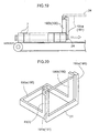
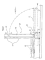
- this type of container group transfer mechanism 2 conventionally employs a construction having a frame 190a with props 190b erected thereon, and a forward-fall preventive device 24 having arms 191a disposed at opposite ends thereof and pivotally supported by the props 190b, whereby the forward-fall preventive device 24 is vertically pivotable to open and close.
- a container group 4 may be moved reliably from the pallet to the conveyer. However, it is necessary to secure a space for movement of the props 190b occurring with the horizontal movement of the container group transfer mechanism 2, and a retraction space for allowing the forward-fall preventive device 24 to retract forwardly and above the container group transfer mechanism 2 when switched to the open state for discharging the container group.
- the container transport is effected at high speed and various containers are transported.
- the containers tumble or become damaged on the conveyer.
- the conventional container group transfer mechanism 2 has problems not only that it is impossible to accommodate, in a space above said receiving device, for example, a monitoring instrument for monitoring a state of the container group transferred to said receiving device, or a device of different function such as a container tumbling preventive mechanism, but that it is impossible to use a conveyer such as an airflow conveyer having an upper guide for tumble preventing purposes.
- a first object of the present invention is to provide a container group transfer mechanism capable of allowing, for example, a monitoring instrument or a device of different function such as a container tumbling preventive mechanism to be disposed in a space above the container group transfer mechanism, or capable of using container transporting equipment with a tumbling preventive upper guide, and container transporting equipment.
- the closure of said forward-fall preventive device and reception of the next container group may be carried out simultaneously to shorten the time taken to receive the container group and to improve the container transporting efficiency container.
- said forward-fall preventive device swings to excess under inertia, instead of stopping in home position, and strikes, with impact, the container received in said container group transfer mechanism, thereby damaging said containers.
- a second object of the present invention is to employs a container group transfer mechanism in which said forward-fall preventive device does not move upward, in order to eliminate the above problem and improve the container transporting efficiency, and to provide a container group transfer mechanism which, even where an arrangement is employed to receive next containers by the time the forward-fall preventive device is closed, reduces the force of inertia acting on the forward-fall preventive device in a closing operation to decrease the impact of contact with the containers, thereby to check damage to the containers.
- the forward-fall preventive device needs to behave in opening or closing time such that containers that tumble easily are transported by deliberately maintaining the contact with the pushing device as far as the airflow conveyer to avoid scattering during the transport, and that containers vulnerable to damage are transported in a rather loose state to check damage by minimizing the pressure of contact among the containers or by the pushing device.
- there is no method for controlling this An apparatus or method having transport functions corresponding to such transport modes has not been developed.
- a third object of the present invention is to provide container transporting equipment and a container transporting method having transport functions corresponding to transport modes for controlling a pushing speed of the pushing device for pushing container groups out onto the airflow conveyer, in relation to a container transport speed of the airflow conveyer, thereby to solve the above problem.
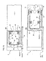
- the invention defined in claim 1, as illustrated in Figs. 1 and 4 to 11, is characterized by a container group transfer mechanism comprising a pushing device 23 for horizontally pushing a container group 4 including a plurality of standing containers arranged and collected in a horizontal direction, by contacting said container group 4 at one side thereof and moving horizontally toward the other side, and a forward-fall preventive device 24 for contacting a forward end in a pushing direction of said container group 4 and switchable between a closed state for lying forwardly in the pushing direction of said container group 4, as said pushing device 23 moves horizontally, to be capable of preventing a forward fall of said containers, and an open state for opening a forward position in the pushing direction of said container group 4 to enable a discharge of the container group 4, wherein said forward-fall preventive device 24 is laterally switchable.
- the invention defined in claim 2, as illustrated in Figs. 1 to 11, is characterized by container transporting equipment comprising a lift device 14 for vertically stacking in stages a plurality of container groups 4 each including a plurality of standing containers arranged and collected in a horizontal direction, and carrying and elevating, stage by stage, said plurality of container groups 4 stacked vertically, a conveyer 17 disposed adjacent said lift device 14 for receiving an uppermost container group elevated by said lift device 14 and transporting the container group horizontally, and a container group transfer mechanism having a pushing device 23 for pushing said uppermost container group 4 onto said conveyer 17 by contacting said container group 4 at one side thereof and moving horizontally toward the other side, and a forward-fall preventive device 24 switchable between a closed state for lying forwardly in a pushing direction of said container group 4, as said pushing device 23 moves horizontally, to be capable of preventing a forward fall of said containers, and an open state for opening a forward position in the pushing direction of said container group when said container group 4 rides said conveyer 17 to enable a discharge
- the invention defined in claim 3, as illustrated in Figs. 12 and 13, is characterized in that said conveyer 17 is an airflow conveyer 12.
- the invention defined in claim 4, as illustrated in Figs. 1 and 4 to 11, is characterized by a container group transfer method comprising horizontally pushing, with a pushing device, a container group including a plurality of standing containers arranged and collected in a horizontal direction, by contacting said container group at one side thereof and moving horizontally toward the other side, and discharging the container group by opening a forward-fall preventive device for contacting a forward end in a pushing direction of said container group and switchable between a closed state for lying forwardly in the pushing direction of said container group, as said pushing device moves horizontally, to be capable of preventing a forward fall of said containers, and an open state for opening a forward position in the pushing direction of said container group to enable a discharge of the container group, in which said container group is discharged by laterally opening said forward-fall preventive device.
- the invention defined in claim 5, as illustrated in Figs. 1 to 11, is characterized by a container group transporting method comprising vertically stacking in stages a plurality of container groups each including a plurality of standing containers arranged and collected in a horizontal direction, and carrying and elevating, stage by stage, with a lift device, said plurality of container groups stacked vertically, horizontally pushing, with a pushing device, an uppermost container group elevated by said lift device by contacting said container group at one side thereof and moving horizontally toward the other side to push said container group onto a conveyer disposed adjacent said lift device for receiving said uppermost container group and transporting the container group horizontally, and discharging said container group by opening a forward-fall preventive device switchable between a closed state for lying forwardly in a pushing direction of said container group, as said pushing device moves horizontally, to be capable of preventing a forward fall of said containers, and an open state for opening a forward position in the pushing direction of said container group when said container group rides said conveyer to enable a discharge of said container group,
- the invention defined in claim 6, as illustrated in Figs. 12 and 13, is characterized in that said conveyer is an airflow conveyer.
- said forward-fall preventive device is laterally openable and closable to allow an effective use of the forward and upper spaces of the container group transfer mechansim.
- the term laterally herein indicates a direction perpendicular to both the upstanding direction of the containers (front-to-back direction relative to the plane of Figs. 10 and 11) and the pushing direction (direction of arrows in Figs. 10 and 11).
- the term forward indicates forward in said pushing direction (direction of the arrow in Fig. 10).
- upper space indicates a space opposite from the conveyor.
- the forward-fall preventive device is vertically openable and closable by pivotal movement of the arms pivotally supported by the props, it is necessary to secure a space for movement of the props occurring with the horizontal movement of the container group transfer mechanism, and a retraction space for allowing the forward-fall preventive device to retract forwardly and above the container group transfer mechanism when switched to the open state for discharging a container group.
- a tall container group in particular requires the forward-fall preventive device to be raised to a height for allowing said container group to be discharged, and a large space to be secured for the forward-fall preventive device to retract forwardly and above the container group transfer mechanism.
- the forward-fall preventive device is laterally openable and closable
- a retraction space is not required for the forward-fall preventive device to retract forwardly and above the container group transfer mechanism.
- the container group transfer mechanism may be disposed in a location having a limited upper space. It is also possible to accommodate, in a space forwardly of and above the container group transfer mechanism, for example, a monitoring instrument or a device of different function such as a container tumbling preventive mechanism.
- the container group transfer mechanism of the present invention improves the degree of freedom of upper space designing, and can cope with a speedup and diversification of container transport.
- This mechanism may easily be introduced into existing container transporting equipment.
- the container transporting equipment has said forward-fall preventive device laterally switchable. It is therefore possible to accommodate a monitoring instrument or a container tumbling preventive mechanism in a space forwardly of and above the receiving portion.
- the forward-fall preventive device may be switched to the open state to open a forward region in the pushing direction of the container group for discharging the container group. Since the forward-fall preventive device is opened laterally, a transport region is not required above the receiving portion for retracting the forward-fall preventive device.
- the container transporting equipment having the container group transfer mechanism may be installed in a location having a limited upward space.
- a monitoring instrument or a device of different function such as a container tumbling preventive mechanism for monitoring presence of damage to or tumbling of the container group transferred to the receiving portion or for preventing tumbling in time of transfer.
- the container transporting equipment has improved functionality to realize smooth transport.
- said conveyer adjacent said lift device need not employ a mechanical conveyer, but may use an airflow conveyer for transporting the containers by means of air.
- an airflow conveyer for transporting the containers by means of air.
- the mechanical conveyer transports containers as placed on an endless rotating member, by frictional contact between the endless rotating member and container bottoms.
- the mechanical conveyer transports containers as placed on an endless rotating member, by frictional contact between the endless rotating member and container bottoms.
- the lift device may elevate a plurality of container groups placed on a pallet, stage by stage, with the container group transfer mechanism transferring the container groups to the adjacent receiving portion of the conveyer.
- the container group transfer mechanism transferring the container groups to the adjacent receiving portion of the conveyer.
- a sufficient number of containers to be discharged from said feeding mechanism within said non-feed time must be stored on the conveyer or transport speed must be increased to prevent an interruption of the containers.
- the mechanical conveyer cannot increase its transport speed for transporting the containers, and the conveyer must have an increased length to store a sufficient number of containers for covering the non-feed time. Thus, the conveyer has to be very long.
- the mechanical conveyer employing a transport mode relying on frictional contact would transmit the transporting force of the endless rotating member directly to a plurality of containers accumulating in said feed mechanism.
- An increased force of contact among the containers could result in damage or collapse.
- a plate-like upper guide or the like may be provided as a tumble preventing mechanism to extend above and parallel to the conveyer from a space above the receiving portion to said feed mechanism for contacting the upper ends of the containers when the containers are about to tumble, thereby preventing tumbling.
- the airflow conveyer may be employed for transporting the containers by means of air. This airflow conveyer moves the containers on the conveyer by blowing air thereto. No frictional contact takes place between the endless rotating member and container bottoms occurring with the mechanical conveyer. Transport speed for transporting the container may be increased. Instead of covering said no-feed time with the number of containers, the containers may be supplied to the feed mechanism without interruption by increasing the transport speed of a next container group. Thus, the conveyer may have a reduced length.
- the container transporting equipment may be made compact to be installable in a small space.
- the containers may also have improved quality.
- the invention defined in claim 7, as illustrated in Fig. 7, is characterized by a container group transfer mechanism comprising a pushing device 23 for horizontally pushing a container group 4 including a plurality of standing containers arranged and collected in a horizontal direction, by contacting said container group 4 at one side thereof and moving horizontally toward the other side, and a forward-fall preventive device 24 for lying forwardly in a pushing direction of said container group 4, as said pushing device 23 moves horizontally, to be capable of preventing a forward fall of said containers, and an open state for opening a forward position in the pushing direction of said container group to enable a discharge of the container group 4, wherein said forward-fall preventive device 24 includes turn elements 40 connected for pivotal movement about rotary shafts 39, rotary drive mechanisms 38 for swinging said turn elements 40 within a predetermined angular range, and gate members 41 fixedly supported by said turn elements for contacting a forward end in a pushing direction of said container group 4 to be capable of preventing a forward fall of the containers, said turn elements 40 being formed to have centers of gravity located
- the invention defined in claim 8, as illustrated in Fig. 9, is characterized in that said forward-fall preventive device includes buffer mechanisms 45 for absorbing inertial swinging of said gate members 41.
- the invention defined in claim 9, as illustrated in Fig. 9, is characterized in that said rotary drive mechanisms 38 are formed of air cylinders 42.
- the invention defined in claim 10, as illustrated in Fig. 8, is characterized in that said gate members 41 have elastic materials 59 provided in positions contactable with the forward end in the pushing direction of said container group 4.
- the invention in claim 7 is capable of reducing the force of inertia acting on the turn elements and gate members during a closing operation.
- each turn element 40 extends to a substantially middle position in the right and left direction of the container group transfer mechanism 2 and fixedly supports the gate member 41 substantially equal in length to said turn element 40, the centers of gravity of the turn elements 40 and the centers of gravity of the gate members 41 are located in approximately the same position.
- the turn elements are formed to have centers of gravity located closer to the rotary shafts than centers of gravity of said gate members.
- the overall center of gravity of the turn elements and gate members regarded as integral is closer to said rotary shafts than in the typical construction shown in Fig. 21. This produces the effect of reducing the force of inertia acting on the turn elements and gate members during a closing operation.
- the impact of the gate members contacting the containers may be reduced to check damage to the containers.
- the impact of the gate members contacting the containers may be further reduced.
- the buffer mechanisms can absorb the force of inertia acting on the turn elements and gate members swinging by inertia. This decreases the impact of the gate members contacting the containers.
- an air cylinder is incapable of fine controls such as stopping rotation at a set position as is possible with a servomotor.
- air cylinders used as the rotary drive mechanisms it is impossible to perform fine controls such as stopping the turn elements and gate members in home position when the forward-fall preventive device is closed.
- the turn elements and gate member could swing to excess to contact the containers with impact, thereby damaging the containers.
- use of the air cylinders is inappropriate.
- By forming the turn elements have centers of gravity located closer to the rotary shafts than the centers of gravity of the gate members as in claim 7, or providing the buffer mechanisms for absorbing inertial swinging of the gate members as in claim 8, the force of inertia acting on the turn elements and gate members may be decreased or absorbed. It is therefore possible to use air cylinders as the rotary drive mechanisms.
- the rotary drive mechansim can employ inexpensive air cylinders, compared with expensive rotary drive mechanisms in the form of servomotors or the like. This realizes a reduction in the cost of the apparatus.
- the gate members are formed of a rigid material such as metal, even though the impact of the gate members contacting the containers is decreased, the rigid metallic gate members transmit the impact as it is to the containers, which could damage the containers.
- the gate members have elastic materials provided in positions contactable with the forward end in the pushing direction of the container group, the impact occurring upon contact with the containers may be absorbed by an elastic deformation of the elastic materials.
- the invention defined in claim 11, as illustrated in Fig. 4, is characterized by container transporting equipment comprising a lift device for vertically stacking in stages a plurality of container groups each including a plurality of standing containers arranged and collected in a horizontal direction, and carrying and elevating, stage by stage, said plurality of container groups stacked vertically, an air conveyer 12 disposed adjacent said lift device for receiving an uppermost container group elevated by said lift device and transporting the container group horizontally, a pushing device 23 for pushing said uppermost container group onto said airflow conveyer 12 by contacting said container group at one side thereof and moving horizontally toward the other side, and a forward-fall preventive device 24 switchable between a closed state for lying forwardly in a pushing direction of said container group 4, as said pushing device 23 moves horizontally, to be capable of preventing a forward fall of said containers, and an open state for opening a forward position in the pushing direction of said container group when said container group rides said airflow conveyer 12 to enable a discharge of said container group, wherein said container transporting equipment comprises a
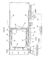
- the invention defined in claim 12, as illustrated in Fig. 14, is characterized by comprising a control device 66 for automatically varying the transport speed of said airflow conveyer 12 and the pushing speed of said pushing device 23.
- the invention defined in claim 13 is characterized in that the pushing speed of said pushing device is set faster than the transport speed of said airflow conveyer.
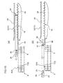
- the invention defined in claim 14 is characterized in that, as said pushing device moves horizontally forward in the pushing direction on said airflow conveyer, said forward-fall preventive device is switched to the open state, and the transport speed of said airflow conveyer is increased the further forward in the direction of transporting the containers.
- the invention defined in claim 15, as illustrated in Fig. 15, is characterized by container transporting equipment comprising a lift device for vertically stacking in stages a plurality of container groups 4 each including a plurality of standing containers 3 arranged and collected in a horizontal direction, and carrying and elevating, stage by stage, said plurality of container groups 4 stacked vertically, an air conveyer 12 disposed adjacent said lift device for receiving an uppermost container group elevated by said lift device and transporting the container group horizontally, a pushing device 23 for pushing said uppermost container group 4 onto said airflow conveyer 12 by contacting said container group 4 at one side thereof and moving horizontally toward the other side, and a forward-fall preventive device 24 switchable between a closed state for lying forwardly in a pushing direction of said container group 4, as said pushing device 23 moves horizontally, to be capable of preventing a forward fall of said containers, and an open state for opening a forward position in the pushing direction of said container group when said container group 4 rides said airflow conveyer 12 to enable a discharge of said container group, wherein said container
- the invention defined in claim 16 is characterized by comprising an upper guide disposed above said airflow conveyer for contacting upper ends of the containers to prevent tumbling of the containers being transported, said forward-fall preventive device being switched in the open state when the horizontal movement of said pushing device 23 brings at least the containers forward in the pushing direction of said container group reach a position under said upper guide.
- the invention defined in claim 17 is characterized by a container group transporting method comprising providing a lift device for vertically stacking in stages a plurality of container groups each including a plurality of standing containers arranged and collected in a horizontal direction, and carrying and elevating, stage by stage, said plurality of container groups stacked vertically, horizontally pushing, with a pushing device, an uppermost container group elevated by said lift device by contacting said container group at one side thereof and moving horizontally toward the other side to push said container group onto an airflow conveyer disposed adjacent said lift device for receiving said uppermost container group and transporting the container group horizontally, and discharging said container group by opening a forward-fall preventive device switchable between a closed state for lying forwardly in a pushing direction of said container group, as said pushing device moves horizontally, to be capable of preventing a forward fall of said containers, and an open state for opening a forward position in the pushing direction of said container group when said container group rides said airflow conveyer to enable a discharge of said container group for transport by said airflow conveyer
- the invention in claim 11 and the invention in claim 17 are capable of varying the transport functions.
- a container group is discharged from the lift device onto the adjacent airflow conveyer.
- the pushing device is moved back onto the lift device to receive a next container group, and receives an uppermost container group elevated by the lift device.
- the pushing device is moved horizontally onto the adjacent airflow conveyer.
- the forward-fall preventive device is switched to the open state. The above step is repeated. A non-feed time not feeding any containers occur until the next container group is discharged onto the airflow conveyer. Because of the non-feed time, an interruption could occur with the containers transported through the single-row transport path.
- This non-feed time is further extended in an operation in which, after discharging a lowermost container on a pallet onto the airflow conveyer, an uppermost container on a next pallet is discharged onto the airflow conveyer.
- the present invention provides a speed varying mechanism for varying a relative speed between the transport speed of the airflow conveyer and the pushing speed of the pushing device.
- a transporting method for avoiding an interruption of the containers transported through the single-row transport path apart from a method for transporting a container group in which the airflow conveyer and pushing device are movable at the same speed, a method may be employed for transporting the containers in which the pushing speed of the pushing device is faster than the transport speed of the airflow conveyer.
- the transport speed of the airflow conveyer may be slowed in order to check tumbling of the containers on the airflow conveyer. Even so, by adjusting the speed of feeding container groups by the pushing device, a sufficient number of containers may be secured on the airflow conveyer to avoid an interruption of the containers transported through the single-row transport path.
- a method may be employed for transporting the containers in which the transport speed of the airflow conveyer is faster than the pushing speed of the pushing device.
- the pushing speed of the pushing device may be slowed in order to discharge the containers onto the airflow conveyer reliably without tumbling. Even so, since the upper guide prevents tumbling of the containers, the transport speed of the airflow conveyer may be adjusted to avoid an interruption of the containers transported through the single-row transport path.
- the containers may be transported in a rather loose state to reduce a contact pressure among the containers or by the pushing device. Damage to containers particularly vulnerable to damage may be checked.
- the container transporting equipment and the container transporting method provided are capable of varying transport speed according to varied shapes the containers and equipment.
- the transport speed of the airflow conveyer and the pushing speed of the pushing device may be varied automatically.
- a control device is provided for varying the transport speed of the airflow conveyer and the pushing speed of the pushing device. For example, by providing sensors for detecting presence or a mounting position of the upper guide and for recognizing shapes such as sizes, intervals between, and tumbling of the containers transported, information may be transmitted to the control device for automatically varying the transport speed of the airflow conveyer and the pushing speed of the pushing device to a proper relative speed. Sensors may be provided for detecting a state of the containers transported. Based on information transmitted from these sensors to the control device, the transport speed of the airflow conveyer and the pushing speed of the pushing device may be varied automatically to a proper relative speed.
- the container transporting equipment provided is capable of automatically varying container transport speed in accordance with varied shapes of containers, installation, and transport conditions.
- the containers when the container group is discharged onto the airflow conveyer by opening the forward-fall preventive device during a horizontal movement forwardly in the pushing direction of the pushing device, the containers may be discharged onto the airflow conveyer while being in contact with one another.
- the pushing speed of the pushing device is set faster than the transporting speed of the airflow conveyer.
- the containers at the forward end of the container group in the pushing device are never transported fast by the airflow conveyer even when the forward-fall preventive device is opened during a horizontal movement forwardly in the pushing direction of the pushing device.
- the containers may be discharged onto the airflow conveyer while being in contact with one another.
- the container transporting equipment provided is capable of checking a forward fall of the containers when the container group is discharged from the lift device onto the airflow conveyer.
- the containers may be discharged from the lift device onto the airflow conveyer steadily and in a reduced time, and the containers discharged may be transported at high speed.
- the time spent to put the forward-fall preventive device in the open state may be included in the horizontal moving time of the pushing device. This realizes a reduction in the container discharging time compared with the case of discharging the containers onto the airflow conveyer after ending the horizontal movement of the pushing device onto the airflow conveyer.
- the containers When, for example, the containers are abruptly discharged to a position of fast transport, the containers tumble easily owing to a difference in relative speed.
- the transport speed of the airflow conveyer is the faster the farther forward in the transporting direction
- the containers may be discharged a position of moderate transport speed of the airflow conveyer, and the containers received may be transported at gradually increased speed.
- the containers may be discharged and transported steadily with little chance of tumbling of the containers.
- the container transporting equipment provided is capable of improving the container transport performance.
- the invention in claim 15 is capable of preventing tumbling of the containers discharged earlier.
- discharging onto the airflow conveyer of container groups by the pushing device is performed in a discharging step repeated at fixed intervals to discharge the container group by opening the forward-fall preventive device when the container group in the pushing device rides the airflow conveyer as the pushing device moves forward in the pushing direction.
- the containers discharged at a preceding discharging step remain in regions of opening of the forward-fall preventive device under some circumstances (e.g. crowding and the like of the containers transported)
- the containers present in the regions of opening of the forward-fall preventive device would be knocked down by the forward-fall preventive device opened in an opening operation.
- detecting sensors are provided for detecting the presence of the containers in the regions of opening of the forward-fall preventive device.
- the forward-fall preventive device is maintained in the close state, thereby to avoid the containers being knocked down by the forward-fall preventive device in the opening operation.
- the forward-fall preventive device is opened and switched to the open state for discharging the container group to execute a normal step of discharging the container group.
- the container transporting equipment provided is capable of improving the container transport performance.
- the containers may be discharged onto the airflow conveyer without tumbling.
- the containers could tumble before reaching the position under the upper guide.
- the container group is discharged by switching the forward-fall preventive device to the open state upon reaching the position under the upper guide.
- the containers may be discharged onto the airflow conveyer without tumbling.
- the container transporting equipment provided is capable of improving the container transport performance.
- Container transporting equipment 1 in one embodiment of the present invention will be described hereinafter with reference to the drawings.
- the container transporting equipment 1 includes a transport conveyer 11 for transporting can group stacks 5 each including a plurality of can groups 6 (one example of container groups 4) vertically stacked on a pallet 9, with separate sheets 8 interposed in between, each can group having a plurality of beer or soft drink cans 7 (one example of containers 3) radially arranged and collected in upstanding posture; a lift device 14 for elevating, stage by stage, each can group stack 5 transported by the transport conveyer 11; an airflow conveyer 12 (one example of conveyer 17) disposed adjacent the lift device 14 for receiving an uppermost one of the can groups 6 elevated by the lift device 14 and horizontally transporting the can group to a next process; a container group transfer mechanism 2 (see Fig.
- said lift device 14 includes a lift deck 15 for supporting each can group stack 5 transported by the transport conveyer 11, and a lift deck moving mechanism 16 for vertically moving the lift deck 15 such as by AC servomotor drive, for example, through gear engagement.
- the lift deck 15 is driven to elevate the can group stack 5 placed thereon, by degrees, one can group 6 after another.
- the pallet 9 no longer needed after discharging all can groups 6 is lowered and the pallet 9 is transferred to the pallet discharge conveyer 13 by a pallet transfer device not shown.
- a single row transport path is disposed at a rear, downstream end of said airflow conveyer, in the form of a funnel with tapering side wall plates of the transport path to feed one can after another to the next process.
- this airflow conveyer 12 includes a deck plate 19 defining a plurality of air blowout bores 18, and a plate-like upper guide 20 disposed above and parallel to the deck plate 19, in a position 3mm to 5mm above the height of the cans.
- the cans 7 are transported downstream in a somewhat floating fashion with air blown against the bottoms of cans 7 placed on the deck plate 19. Even when the cans start tumbling at this time, the tops thereof will contact the upper guide 20, whereby the cans 7 are prevented from tumbling. This is due to no clearance being allowed between the cans 7 and upper guide 20.
- said upper guide 20 is supported by and fixed at side walls thereof to opposite side walls of the airflow conveyer 12 by air cylinders, not shown, erected in a plurality of locations along the transport direction.
- the guide is switchable to a height matched to the cans 7 transported (long cans or short cans) in a one-touch operation of a push-button switch to operate the air cylinders.
- the push-button switch is pressed to operate the air cylinders in a one-touch operation to switch the upper guide 20 to a low set position to prevent tumbling of the low cans 7a.
- the push-button switch is pressed to operate the air cylinders in a one-touch operation to switch the upper guide 20 to a high set position to prevent tumbling of the high cans 7a.
- said pushing device 23 includes a frame 26 U-shaped in plan view and having three hold bars 25 arranged in three inner positions and protrudable and retractable by air cylinders 34, and a frame moving mechanism 33 having engaging members 28 attached to a plurality of brackets 27 fixed below the frame 26 and engaged, supported and guided by guide rails 29 attached to frame supporting side walls, and an arm extending laterally outward from an upper position of the frame 26 and gripping a belt 32 driven by a servomotor 31, thereby horizontally moving the frame 26 forward and backward with forward and backward movement of the belt 32 in the pushing direction of the can group 6.
- each said hold bars 25 has a bar member 36 formed of a resin and fitted on a plate 35 attached to cylinder rods of the air cylinders 34.
- the cans 7 have a reduced chance of being damaged when contacting the bar members 36.
- Numeral 37 in Fig. 4 denotes slide shafts arranged at the right and left sides of air cylinders 34 for guiding the hold bars 25 in the protrusion and retraction by the air cylinders 34 without causing complication.
- said forward-fall preventive device 24 includes a pair of rotary drive mechanisms 38 for swing driving within a predetermined angular range, a turn element 40 pivotally connected to a rotary shaft 39 of each rotary drive mechansim 38, and a gate member 41 fixedly supported by the rotating member for contacting a forward end in the pushing direction of the can group 6 to prevent a forward fall of the cans 7.
- the gate members 41 are driven by the rotary drive mechanisms 38 to swing open and close in double-door fashion.
- the turn elements 40 have a short extending length to have the centers of gravity located closer to the rotary shafts than the centers of gravity of the gate members. This reduces the force of inertia acting on the turn elements and gate members in a closing operation, to decrease the impact of the gate members 41 contacting the cans 7 and check damage to the cans 7.
- said gate member 41 has a gate bar 60 formed of polyethylene resin (one example of elastic material 59) and engaged and supported by a channel-shaped mount 61 attached to the turn element 40, in a position of the gate member 41 contacting the forward end in the pushing direction of can group 6. With this, the impact occurring in time of contact with the can group 6 may be absorbed by elastic deformation of the polyethylene resin to check damage to the cans 7.
- the gate member 41 undergoes severe damage or wear in positions contacting can groups 6.
- the gate bar 60 engaged and supported by the mount 61 may only be released and replaced with a new gate bar 60. This provides for improved economy and efficiency of changing operation.
- said rotary drive mechansim 38 comprises air cylinders 42 with a pinion gear 39a mounted on the rotary shaft 39, racks 43a and 43b formed on right and left pistons 43A and 43B, respectively, and engaged with the pinion gear 39a. Air is supplied into and exhausted from cylinders 44 to move the pistons 43A and 43B.
- cushion rubber elements 46a and 46b are disposed at end surfaces in the respective cylinders 44A and 44B.
- an opening operation to the open state to open a forward position in the pushing direction of can group 6 for discharging the can group 6 an end surface of the piston 43A contacts the cushion rubber 46a.
- An elastic deformation of cushion rubber 46a absorbs the force of inertia occurring with the opening operation to act on the turn element 40 and gate member 41.
- an end surface of piston 43B contacts the cushion rubber 46b.
- cushion rubber 46b absorbs the force of inertia occurring with the closing operation to act on the turn element 40 and gate member 41. This decreases the impact of the gate member 41 contacting the cans 7 to check damage to the cans 7. (see Fig. 9)
- the present invention provides container transporting equipment including a lift device for vertically stacking in stages a plurality of container groups each including a plurality of standing containers arranged and collected in a horizontal direction, and carrying and elevating, stage by stage, said plurality of container groups stacked vertically, provides an air conveyer adjacent the lift device for receiving an uppermost container group elevated by the lift device and transporting the container group horizontally, a pushing device for pushing the uppermost container group onto the adjacent airflow conveyer by contacting the container group at one side thereof and moving horizontally toward the other side, and a forward-fall preventive device switchable between a closed state for lying forwardly in a pushing direction of the container group, as the pushing device moves horizontally, to be capable of preventing a forward fall of containers, and an open state for opening a forward position in the pushing direction of the container group when the container group rides the airflow conveyer to enable a discharge of the container group, to transport the container group effectively.
Landscapes
- De-Stacking Of Articles (AREA)
- Intermediate Stations On Conveyors (AREA)
- Pile Receivers (AREA)
Abstract
Description
Claims (17)
- A container group transfer mechanism comprising a pushing device (23) for horizontally pushing a container group (4) including a plurality of standing containers arranged and collected in a horizontal direction, by contacting said container group (4) at one side thereof and moving horizontally toward the other side, and a forward-fall preventive device (24) for contacting a forward end in a pushing direction of said container group (4) and switchable between a closed state for lying forwardly in the pushing direction of said container group (4), as said pushing device (23) moves horizontally, to be capable of preventing a forward fall of said containers, and an open state for opening a forward position in the pushing direction of said container group to enable a discharge of the container group (4), wherein said forward-fall preventive device (24) is laterally switchable.
- Container transporting equipment comprising a lift device (14) for vertically stacking in stages a plurality of container groups (4) each including a plurality of standing containers arranged and collected in a horizontal direction, and carrying and elevating, stage by stage, said plurality of container groups (4) stacked vertically, a conveyer (17) disposed adjacent said lift device (14) for receiving an uppermost container group elevated by said lift device (14) and transporting the container group horizontally, and a container group transfer mechanism having a pushing device (23) for pushing said uppermost container group (4) onto said conveyer (17) by contacting said container group (4) at one side thereof and moving horizontally toward the other side, and a forward-fall preventive device (24) switchable between a closed state for lying forwardly in a pushing direction of said container group (4), as said pushing device (23) moves horizontally, to be capable of preventing a forward fall of said containers, and an open state for opening a forward position in the pushing direction of said container group when said container group (4) rides said conveyer (17) to enable a discharge of said container group (4), wherein said forward-fall preventive device (24) is laterally switchable.
- Container transporting equipment as defined in claim 2, wherein said conveyer (17) is an airflow conveyer (12).
- A container group (4) transfer method comprising horizontally pushing, with a pushing device (23), a container group (4) including a plurality of standing containers arranged and collected in a horizontal direction, by contacting said container group (4) at one side thereof and moving horizontally toward the other side, and discharging the container group (4) by opening a forward-fall preventive device (24) for contacting a forward end in a pushing direction of said container group (4) and switchable between a closed state for lying forwardly in the pushing direction of said container group (4), as said pushing device (23) moves horizontally, to be capable of preventing a forward fall of said containers, and an open state for opening a forward position in the pushing direction of said container group to enable a discharge of the container group (4), characterized in that said container group (4) is discharged by laterally opening said forward-fall preventive device (24).
- A container group transporting method comprising vertically stacking in stages a plurality of container groups (4) each including a plurality of standing containers arranged and collected in a horizontal direction, and carrying and elevating, stage by stage, with a lift device (14), said plurality of container groups (4) stacked vertically, horizontally pushing, with a pushing device (23), an uppermost container group elevated by said lift device (14) by contacting said container group (4) at one side thereof and moving horizontally toward the other side to push said container group (4) onto a conveyer (17) disposed adjacent said lift device (14) for receiving said uppermost container group and transporting the container group horizontally, and discharging said container group (4) by opening a forward-fall preventive device (24) switchable between a closed state for lying forwardly in a pushing direction of said container group (4), as said pushing device (23) moves horizontally, to be capable of preventing a forward fall of said containers, and an open state for opening a forward position in the pushing direction of said container group when said container group (4) rides said conveyer (17) to enable a discharge of said container group (4), characterized in that said container group (4) is discharged by laterally opening said forward-fall preventive device (24).
- A container group transporting method as defined in claim 5, wherein said conveyer (17) is an airflow conveyer (12).
- A container group transfer mechanism comprising a pushing device (23) for horizontally pushing a container group (4) including a plurality of standing containers arranged and collected in a horizontal direction, by contacting said container group (4) at one side thereof and moving horizontally toward the other side, and a forward-fall preventive device (24) for lying forwardly in a pushing direction of said container group (4), as said pushing device (23) moves horizontally, to be capable of preventing a forward fall of said containers, and an open state for opening a forward position in the pushing direction of said container group to enable a discharge of the container group (4), wherein said forward-fall preventive device (24) includes turn elements (40) connected for pivotal movement about rotary shafts (39), rotary drive mechanisms (38) for swinging said turn elements (40) within a predetermined angular range, and gate members (41) fixedly supported by said turn elements for contacting a forward end in a pushing direction of said container group (4) to be capable of preventing a forward fall of the containers, said turn elements (40) being formed to have centers of gravity located closer to said rotary shafts (38) than centers of gravity of said gate members (41).
- A container group transfer mechanism as defined in claim 7, wherein said forward-fall preventive device (24) includes buffer mechanisms (45) for absorbing inertial swinging of said gate members (41).
- A container group transfer mechanism as defined in claim 7 or 8, wherein said rotary drive mechanisms (38) are formed of air cylinders (42).
- A container group transfer mechanism as defined in any one of claims 7 to 9, wherein said gate members (41) have elastic materials 59 provided in positions contactable with the forward end in the pushing direction of said container group (4).
- Container transporting equipment comprising a lift device (14) for vertically stacking in stages a plurality of container groups (4) each including a plurality of standing containers arranged and collected in a horizontal direction, and carrying and elevating, stage by stage, said plurality of container groups (4) stacked vertically, an air conveyer (12) disposed adjacent said lift device (14) for receiving an uppermost container group elevated by said lift device (14) and transporting the container group horizontally, a pushing device (23) for pushing said uppermost container group (4) onto said airflow conveyer (12) by contacting said container group (4) at one side thereof and moving horizontally toward the other side, and a forward-fall preventive device (24) switchable between a closed state for lying forwardly in a pushing direction of said container group (4), as said pushing device (23) moves horizontally, to be capable of preventing a forward fall of said containers, and an open state for opening a forward position in the pushing direction of said container group when said container group (4) rides said airflow conveyer (12) to enable a discharge of said container group (4), wherein said container transporting equipment comprises a speed varying mechanism (62) for varying a relative speed between a transport speed of said airflow conveyer (12) and a pushing speed of said pushing device (23).
- Container transporting equipment as defined in claim 11, comprising a control device (66) for automatically varying the transport speed of said airflow conveyer (12) and the pushing speed of said pushing device (23).
- Container transporting equipment as defined in claim 11 or 12, wherein the pushing speed of said pushing device (23) is set faster than the transport speed of said airflow conveyer (12).
- Container transporting equipment as defined in claim 11 or 14, wherein, as said pushing device (23) moves horizontally forward in the pushing direction on said airflow conveyer (12), said forward-fall preventive device (24) is switched to the open state, and the transport speed of said airflow conveyer (12) is increased the further forward in the direction of transporting the containers.
- Container transporting equipment comprising a lift device (14) for vertically stacking in stages a plurality of container groups (4) each including a plurality of standing containers arranged and collected in a horizontal direction, and carrying and elevating, stage by stage, said plurality of container groups (4) stacked vertically, an air conveyer (12) disposed adjacent said lift device (14) for receiving an uppermost container group elevated by said lift device (14) and transporting the container group horizontally, a pushing device (23) for pushing said uppermost container group (4) onto said airflow conveyer (12) by contacting said container group (4) at one side thereof and moving horizontally toward the other side, and a forward-fall preventive device (24) switchable between a closed state for lying forwardly in a pushing direction of said container group (4), as said pushing device (23) moves horizontally, to be capable of preventing a forward fall of said containers, and an open state for opening a forward position in the pushing direction of said container group when said container group (4) rides said airflow conveyer (12) to enable a discharge of said container group, wherein said container transporting equipment comprises detecting sensors (67) for detecting presence of containers in regions where an opening operation of said forward-fall preventive device (24) takes place, and a control device (68) for maintaining said forward-fall preventive device (24) in the closed state when said detecting sensors (67) detect the containers present in the regions of opening, even if said container group (4) is brought by said pushing device (23) onto said airflow conveyer (12), and for switching said forward-fall preventive device (24) to the open state for discharging said container group (4) when an absence of containers is detected.
- Container transporting equipment as defined in claims 11 to 14, comprising an upper guide (20) disposed above said airflow conveyer (12) for contacting upper ends of the containers to prevent tumbling of the containers being transported, said forward-fall preventive device (24) being switched in the open state when the horizontal movement of said pushing device (23) brings at least the containers forward in the pushing direction of said container group (4) reach a position under said upper guide (20).
- A container group transporting method comprising providing a lift device (14) for vertically stacking in stages a plurality of container groups (4) each including a plurality of standing containers arranged and collected in a horizontal direction, and carrying and elevating, stage by stage, said plurality of container groups (4) stacked vertically, horizontally pushing, with a pushing device (23), an uppermost container group elevated by said lift device (14) by contacting said container group (4) at one side thereof and moving horizontally toward the other side to push said container group (4) onto an airflow conveyer (12) disposed adjacent said lift device (14) for receiving said uppermost container group and transporting the container group horizontally, and discharging said container group (4) by opening a forward-fall preventive device (24) switchable between a closed state for lying forwardly in a pushing direction of said container group (4), as said pushing device (23) moves horizontally, to be capable of preventing a forward fall of said containers, and an open state for opening a forward position in the pushing direction of said container group when said container group (4) rides said airflow conveyer (12) to enable a discharge of said container group (4) for transport by said airflow conveyer (12), characterized in that said container group (4) is discharged by freely varying a relative speed between a transport speed of said airflow conveyer (12) and a pushing speed of said pushing device (23).
Applications Claiming Priority (7)
| Application Number | Priority Date | Filing Date | Title |
|---|---|---|---|
| JP2000319261A JP4574829B2 (en) | 2000-10-19 | 2000-10-19 | Container group delivery mechanism and container transport equipment |
| JP2000319261 | 2000-10-19 | ||
| JP2001221542A JP4911840B2 (en) | 2001-07-23 | 2001-07-23 | Container transport equipment and container transport method |
| JP2001221542 | 2001-07-23 | ||
| JP2001221541A JP4955869B2 (en) | 2001-07-23 | 2001-07-23 | Container group delivery device |
| JP2001221541 | 2001-07-23 | ||
| PCT/JP2001/009165 WO2002032796A1 (en) | 2000-10-19 | 2001-10-18 | Container group delivery mechanism, and equipment and method for transporting container |
Publications (2)
| Publication Number | Publication Date |
|---|---|
| EP1334928A1 true EP1334928A1 (en) | 2003-08-13 |
| EP1334928A4 EP1334928A4 (en) | 2004-03-24 |
Family
ID=27344972
Family Applications (1)
| Application Number | Title | Priority Date | Filing Date |
|---|---|---|---|
| EP01976751A Withdrawn EP1334928A4 (en) | 2000-10-19 | 2001-10-18 | Container group delivery mechanism, and equipment and method for transporting container |
Country Status (5)
| Country | Link |
|---|---|
| US (1) | US6915895B2 (en) |
| EP (1) | EP1334928A4 (en) |
| CN (1) | CN1222458C (en) |
| TW (1) | TW520337B (en) |
| WO (1) | WO2002032796A1 (en) |
Cited By (1)
| Publication number | Priority date | Publication date | Assignee | Title |
|---|---|---|---|---|
| ITBG20110026A1 (en) * | 2011-06-27 | 2012-12-28 | Ennio Mazzola | SYSTEM FOR DOWNLOADING BOOKS FROM A PALLET |
Families Citing this family (15)
| Publication number | Priority date | Publication date | Assignee | Title |
|---|---|---|---|---|
| JP5414166B2 (en) * | 2007-10-29 | 2014-02-12 | サントリーホールディングス株式会社 | Laser printing apparatus and laser printing method |
| US20090112675A1 (en) * | 2007-10-31 | 2009-04-30 | Jeff Servais | Automated order fulfillment system and method |
| DE102011103563A1 (en) * | 2011-05-30 | 2012-12-06 | Winkler + Dünnebier Gmbh | Method for transferring articles and deflection unit |
| CN105406145B (en) * | 2015-11-20 | 2017-12-12 | 襄阳远锐资源工程技术有限公司 | A kind of waste and old lead acid accumulator stacking and de-stacking device and method |
| CN105416675A (en) * | 2015-12-25 | 2016-03-23 | 嘉兴市新发现机械制造有限公司 | Conveying mechanism for cylindrical paper container packaging and bagging machine |
| CN105731012B (en) * | 2016-03-14 | 2018-01-05 | 昆明昆船物流信息产业有限公司 | A kind of full-automatic battery being connected between storage production tears code, induction system open |
| CN106477299B (en) * | 2016-11-04 | 2018-11-06 | 上海龙应自动化科技有限公司 | Packing box conveying equipment |
| CN107352263B (en) * | 2017-09-08 | 2023-08-08 | 杭州中水机器人制造有限公司 | Robot palletizer shovel plate mechanism |
| CN108974931A (en) * | 2018-07-25 | 2018-12-11 | 会稽山绍兴酒股份有限公司 | A kind of flat-pushing blanking partition transfer equipment |
| CN109305551A (en) * | 2018-12-03 | 2019-02-05 | 深圳市微特自动化设备有限公司 | A kind of standardization pcb board testing automatic material-feeding device |
| CN110668120A (en) * | 2019-09-29 | 2020-01-10 | 陆秀权 | Feeding device with separation function for production line |
| IT202200012140A1 (en) * | 2022-06-08 | 2023-12-08 | Flexlink Systems S P A | Device for picking stacked products and method for picking stacked products on pallets |
| US12330889B1 (en) * | 2022-10-11 | 2025-06-17 | Bw Integrated Systems, Llc | Depalletizing machine |
| CN118753776A (en) * | 2024-09-03 | 2024-10-11 | 浙江云度新材料科技有限公司 | A control method for a NdFeB magnet discharging and conveying device |
| CN119218681B (en) * | 2024-11-28 | 2025-05-30 | 长春博达汽车零部件有限公司 | Automobile parts transportation equipment and transportation method thereof |
Family Cites Families (11)
| Publication number | Priority date | Publication date | Assignee | Title |
|---|---|---|---|---|
| GB1327882A (en) * | 1970-05-19 | 1973-08-22 | Windmoeller & Hoelscher | Apparatus for forming and conveying stacks of flat articles |
| JPS5843526Y2 (en) * | 1979-05-24 | 1983-10-03 | シ−ケ−ディ株式会社 | Pillow-shaped package charging device |
| JPS5843526A (en) | 1981-09-09 | 1983-03-14 | Toshiba Corp | Manufacture of semiconductor device |
| JPH0635286B2 (en) * | 1982-04-23 | 1994-05-11 | 山之内製薬株式会社 | Vacuum freeze dryer |
| JPS59134122A (en) * | 1983-01-20 | 1984-08-01 | 渋谷工業株式会社 | Vessel grouping device in caser |
| US5069598A (en) * | 1988-10-24 | 1991-12-03 | Am International Incorporated | Apparatus and method for loading sheet material articles |
| DE69413573T2 (en) | 1993-02-12 | 1999-05-06 | Goldco Industries Inc., Loveland, Col. | Palletizer / depalletizer for objects |
| US5310307A (en) | 1993-02-12 | 1994-05-10 | Goldco Industries, Inc. | Depalletizing device and method |
| US5489016A (en) * | 1994-11-29 | 1996-02-06 | Technical Industrial Development Enterprises, Inc. | Pusher bar apparatus to remove containers from a splice plate between conveyors |
| US5733100A (en) * | 1996-10-09 | 1998-03-31 | Plastipak Packaging, Inc. | Cylindrical object palletizer |
| US5902092A (en) * | 1997-06-25 | 1999-05-11 | Neos, Inc. | Self-clearing transfer arms |
-
2001
- 2001-10-18 EP EP01976751A patent/EP1334928A4/en not_active Withdrawn
- 2001-10-18 WO PCT/JP2001/009165 patent/WO2002032796A1/en not_active Ceased
- 2001-10-18 US US10/149,831 patent/US6915895B2/en not_active Expired - Fee Related
- 2001-10-18 CN CNB01804932XA patent/CN1222458C/en not_active Expired - Fee Related
- 2001-10-19 TW TW090125942A patent/TW520337B/en not_active IP Right Cessation
Cited By (1)
| Publication number | Priority date | Publication date | Assignee | Title |
|---|---|---|---|---|
| ITBG20110026A1 (en) * | 2011-06-27 | 2012-12-28 | Ennio Mazzola | SYSTEM FOR DOWNLOADING BOOKS FROM A PALLET |
Also Published As
| Publication number | Publication date |
|---|---|
| CN1222458C (en) | 2005-10-12 |
| EP1334928A4 (en) | 2004-03-24 |
| US6915895B2 (en) | 2005-07-12 |
| TW520337B (en) | 2003-02-11 |
| US20030102201A1 (en) | 2003-06-05 |
| WO2002032796A1 (en) | 2002-04-25 |
| CN1400952A (en) | 2003-03-05 |
Similar Documents
| Publication | Publication Date | Title |
|---|---|---|
| US6915895B2 (en) | Container group delivery mechanism, and equipment and method for transporting container | |
| US7096650B2 (en) | Device for filling a carton | |
| US6474462B2 (en) | Apparatus for conveying and temporarily storing products | |
| CN112340410B (en) | Feed sorting device and feed sorting method | |
| US20090175691A1 (en) | Pneumatic conveyor for bottles | |
| US20150284192A1 (en) | Device and method for stacking and de-stacking goods carriers | |
| KR0141351B1 (en) | Tray conveying method and device | |
| EA013584B1 (en) | Apparatus for placing battery plates | |
| US11518626B2 (en) | Transfer device for transferring eggs and device for transporting and packaging eggs | |
| CN115743762A (en) | Automatic packaging machine for easy-to-open lid | |
| CN113716094A (en) | Glass bottle boxing machine | |
| US20240158188A1 (en) | Container lifting and emptying device | |
| GB2147282A (en) | Storage plant | |
| CN213536393U (en) | Feeding and sorting device | |
| CN117342068B (en) | A gauze multi-channel three-dimensional aggregate packaging system | |
| JP4955869B2 (en) | Container group delivery device | |
| KR100615543B1 (en) | Ampoule water supply device | |
| JP2022118684A (en) | Cold insulator aligning and conveying device | |
| CN216835942U (en) | Discharging machine head | |
| CN109178454B (en) | Gift bag filling device | |
| JP4911840B2 (en) | Container transport equipment and container transport method | |
| CN213536073U (en) | Goods taking rack and goods sorting system | |
| KR100223094B1 (en) | Tube loading and unloading device of vertical handler | |
| JP4492832B2 (en) | Alignment device | |
| JP4367680B2 (en) | Cutting device |
Legal Events
| Date | Code | Title | Description |
|---|---|---|---|
| PUAI | Public reference made under article 153(3) epc to a published international application that has entered the european phase |
Free format text: ORIGINAL CODE: 0009012 |
|
| 17P | Request for examination filed |
Effective date: 20030502 |
|
| AK | Designated contracting states |
Designated state(s): AT BE CH CY DE DK ES FI FR GB GR IE IT LI LU MC NL PT SE TR |
|
| AX | Request for extension of the european patent |
Extension state: AL LT LV MK RO SI |
|
| A4 | Supplementary search report drawn up and despatched |
Effective date: 20040205 |
|
| RIC1 | Information provided on ipc code assigned before grant |
Ipc: 7B 65G 59/02 B Ipc: 7B 65G 47/82 A |
|
| 17Q | First examination report despatched |
Effective date: 20051007 |
|
| GRAP | Despatch of communication of intention to grant a patent |
Free format text: ORIGINAL CODE: EPIDOSNIGR1 |
|
| STAA | Information on the status of an ep patent application or granted ep patent |
Free format text: STATUS: THE APPLICATION IS DEEMED TO BE WITHDRAWN |
|
| 18D | Application deemed to be withdrawn |
Effective date: 20080624 |