EP1334849A1 - Luftmischvorrichtung für eine Fahrzeugklimatisierungseinrichtung - Google Patents
Luftmischvorrichtung für eine Fahrzeugklimatisierungseinrichtung Download PDFInfo
- Publication number
- EP1334849A1 EP1334849A1 EP03001566A EP03001566A EP1334849A1 EP 1334849 A1 EP1334849 A1 EP 1334849A1 EP 03001566 A EP03001566 A EP 03001566A EP 03001566 A EP03001566 A EP 03001566A EP 1334849 A1 EP1334849 A1 EP 1334849A1
- Authority
- EP
- European Patent Office
- Prior art keywords
- control surface
- radial
- axial
- inflow opening
- air
- Prior art date
- Legal status (The legal status is an assumption and is not a legal conclusion. Google has not performed a legal analysis and makes no representation as to the accuracy of the status listed.)
- Granted
Links
Images


Classifications
-
- B—PERFORMING OPERATIONS; TRANSPORTING
- B60—VEHICLES IN GENERAL
- B60H—ARRANGEMENTS OF HEATING, COOLING, VENTILATING OR OTHER AIR-TREATING DEVICES SPECIALLY ADAPTED FOR PASSENGER OR GOODS SPACES OF VEHICLES
- B60H1/00—Heating, cooling or ventilating devices
- B60H1/00642—Control systems or circuits; Control members or indication devices for heating, cooling or ventilating devices
- B60H1/00664—Construction or arrangement of damper doors
- B60H1/00671—Damper doors moved by rotation; Grilles
- B60H1/00685—Damper doors moved by rotation; Grilles the door being a rotating disc or cylinder or part thereof
Definitions
- the present invention relates to an air mixing device for an air conditioning device a vehicle, in particular a motor vehicle.
- a tempered and in particular introduced a dried air flow in a vehicle interior become.
- a Cold air stream suitably mixed with a stream of hot air to Set the desired air temperature via the mixing ratio.
- the mixture of cold air with the hot air takes place in an air mixing device of the type mentioned initially, usually a component the air conditioning device forms.
- an air mixing device of the type mentioned initially, usually a component the air conditioning device forms.
- Control organs are provided, with which the connections of a hot air duct and a cold air duct with a mixing space in a suitable manner can be controlled.
- the present invention addresses the problem of an air mixing device of the type mentioned an improved embodiment specify, in particular, a particularly compact design has.
- the invention is based on the general idea, on a single Control member an axial control surface for controlling an axial inflow opening and a radial control surface for controlling a radial inflow opening form, wherein the control member about a pivot axis is rotatable, which is perpendicular to the axial control surface.
- the Control member thus forms a combination of a swash plate (axial control surface) and a rotary valve (radial control surface).
- a swash plate axial control surface
- a rotary valve radial control surface
- the radial control surface the e.g. essentially the shape of a shell of a half cylinder or half truncated cone has, connect radially outward to the axial control surface, which, for example, has substantially the shape of a semicircular disk. Due to this construction, the control member is particularly compact and geometrically simple.
- the control organ can be as a solid or be designed as shell body, the shell body variant relative inexpensive is feasible.
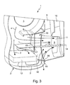
- FIGs. 1 to 3 comprises an air mixing device according to the invention 1 a housing 2 containing a mixing chamber 3.
- a first flow path or path 4 is formed, which in Figs. 1 and 3 is symbolized by flow arrows and an air inlet 5 by a first inflow opening 6 leads to the mixing chamber 3.
- From the mixing room 3 go out different outflow channels 9, 10, 11 from the mixing room 3 e.g. to outlet nozzles, not shown, of an air conditioning device a vehicle, in particular a motor vehicle lead, with their Help air conditioned air is inflatable into a vehicle interior.
- the air mixing device 1 forms a part of this air conditioning device.
- a permeable radiator 12 is arranged, the flow through it transfers heat to the air flow flowing through it.
- the second Flow path 7 following air flow thus forms a hot air flow, while the flow of air following the first flow path 4 is the radiator 12 bypasses and thus forms a cold air flow.
- a control member 13 about a pivot axis 14 is rotationally adjustable stored.
- This control member 13 is here in the form of a longitudinal direction formed halved, axially open pot and therefore has a half bottom 15 in the form of a semicircular disk and a radial outside adjoining half-shell 16 in the form of a half-cylinder or half-cone stump.
- the half-bottom 15 forms an axial control surface the control member 13, which is also referred to below with 15 becomes.
- This axial control surface 15 thus extends perpendicular to Pivot axis 14 of the control member 13 and is the first inflow opening. 6 associated with the rotatable control member 13 axially aligned is.
- the inflow direction in the first inflow opening 6 extends substantially parallel to the pivot axis 14. Accordingly, the first inflow opening 6 hereinafter also referred to as axial inflow opening 6.
- the half-shell 16 forms a radial Control surface, which is also referred to as 16 below.
- This radial Control surface 16 is radially spaced from the pivot axis 14 and is substantially in the direction thereof, that is, the radial control surface 16 extends parallel, (as far as the half-shell 16 of a Semi-cylinder acts) or substantially parallel (as far as the Half-shell 16 of a half truncated cone is) to the pivot axis 14 and in the circumferential direction of the respective half-cylinder or Halbkegelstumpfs.
- the radial control surface 16 is associated with the second inflow opening 8, which is also referred to below as the radial inflow opening 8, since they with respect to the control member 13 is arranged substantially radially, with the result that in the radial inflow opening 8, the supplied air flow with respect to the pivot axis 14 flows substantially radially.
- the axial control surface 15 is in its center of rotation 17 on a drive shaft 18 rotatably mounted, which extends coaxially to the pivot axis 14 and which is rotatably mounted in the housing 2.
- the drive shaft 18th can manually via a suitable, not shown here actuator and / or motor driven to the control member 13 to rotate adjust.
- the axial control surface 15 and the radial control surface 16 may be as one piece Component, in particular as injection-molded component, blow-molded part, vacuum-drawn part or extrusion formed.
- the attached drive shaft 18 can also be formed so that the control member 13 including its drive shaft 18 forms a one-piece component.
- a sealing lip 19 may be formed or formed on the control member 13. at The embodiment shown here is a semicircular sealing lip 19th at the axial end remote from the axial control surface 15 of the radial Control surface 16 is formed. This sealing lip 19 is in a corresponding Guided guide 20 of the housing 2 and thereby ensures a precise adjustability of the control member 13 in the housing. 2
- the axial control surface 15 is associated with the axial inflow opening 6, the means, depending on the rotational position of the control member 13 closes the axial control surface 15 more or less the connection of the axial inflow opening 6 with the mixing chamber 3 and thereby regulated over the first flow path 4 through the axial inflow opening 6 in the mixing chamber 3 incoming air quantity.
- the radial control surface 16 of the radial inflow opening 8 associated so that the radial control surface 16 depending on the rotational position of the control member 13, the radial Inflow opening 8 closes more or less. This means that the radial Control surface 16 depending on their rotational position the connection between the radial inflow opening 8 and the mixing chamber 3 and thus the volume flow in the second flow path 7 through the radial inflow opening 8 in the mixing chamber 3 controls.
- the control member 13 assumes a first position in which the axial Control surface 15, the axial inflow opening 6 maximum opens while the radial control surface 16, the radial inflow 8 maximum, here completely closes. In this first position is thus only the first flow path 4, so here the cold air flow active. Accordingly, the mixing chamber 3 in the first position only supplied with cold air.
- the control member 13 can be transferred to a second position, in FIG the axial control surface 15, the axial inflow port 6 maximum, here completely closes while the radial control surface 16, the radial inflow opening 8 maximum opens.
- this second position is thus only the second flow path 7 is activated so that only the radiator 12 flowing air, so warm air enters the mixing chamber 3.
- the rotary member 13 is about its pivot axis 14th rotated by 180 °. Between these positions according to FIGS. 1 and 2 can the control member 13 any intermediate positions or mixing positions occupy, one of which is exemplified in Fig. 3, in the the rotary member 13 rotated by 90 ° relative to the other two positions is. In this mixing position, the axial control surface 15 closes the axial inflow 6 only partially, here half, so that more or less Cold air entering through the axial inflow opening 6 in the mixing chamber 3 can.
- both flow paths 4 and 7 activated, so that the supplied via the inlet opening 5 air flow,
- the two inflow openings 6 and 8 divides.
- control member 13 a particularly compact design for the Air mixing device 1 can be achieved.
- control member 13 is appropriate stored so that it is almost endlessly rotatable in the same direction.
- the control member 13 with its control surfaces 15, 16 formed as a relatively thin-walled shell body, the characterized by a particularly low weight.
- the control member 13 is also possible to form the control member 13 as a solid body, the Control surfaces 15, 16 has.
- control member 13 to 180 ° must be rotated to the two inflow openings 6 and 8 maximum To lock or maximum open, it can in another embodiment also be expedient to design the control member 13 so and the inflow openings 6 and 8 to be arranged so that even a smaller Angle of rotation is sufficient to reach these two extreme positions.
Landscapes
- Physics & Mathematics (AREA)
- Thermal Sciences (AREA)
- Engineering & Computer Science (AREA)
- Mechanical Engineering (AREA)
- Air-Conditioning For Vehicles (AREA)
- Air-Flow Control Members (AREA)
Abstract
Description
- Fig. 1 bis 3
- teilweise geschnittene, dreidimensionale Ansichten auf eine Luftmischvorrichtung nach der Erfindung bei unterschiedlichen Stellungen eines Steuerorgans.
- 1
- Luftmischvorrichtung
- 2
- Gehäuse
- 3
- Mischraum
- 4
- erster Strömungsweg/Kaltluft
- 5
- Einlaßöffnung
- 6
- erste Zuströmöffnung/axiale Zuströmöffnung
- 7
- zweiter Strömungsweg/Warmluft
- 8
- zweite Zuströmöffnung/radiale Zuströmöffnung
- 9
- Abströmkanal
- 10
- Abströmkanal
- 11
- Abströmkanal
- 12
- Heizgerät
- 13
- Steuerorgan
- 14
- Schwenkachse von 13
- 15
- Halbboden/axiale Steuerfläche von 13
- 16
- Halbmantel/radiale Steuerfläche von 13
- 17
- Zentrum von 15
- 18
- Antriebswelle
- 19
- Dichtlippe von 13
- 20
- Führung von 13 an/in 2
Claims (8)
- Luftmischvorrichtung für eine Klimatisierungseinrichtung eines Fahrzeugs, insbesondere eines Kraftfahrzeugs,
mit einem Steuerorgan (13),wobei das Steuerorgan (13) zwischendas um eine Schwenkachse (14) drehverstellbar gelagert ist,das eine axiale Steuerfläche (15) aufweist, die im wesentlichen senkrecht zur Schwenkachse (14) verläuft und in Abhängigkeit der Drehlage des Steuerorgans (13) eine axiale Zuströmöffnung (6) mehr oder weniger mit einem Mischraum (3) verbindet,das eine radiale Steuerfläche (16) aufweist, die von der Schwenkachse (14) radial beabstandet ist, sich im wesentlichen parallel zur Schwenkachse (14) erstreckt, und in Abhängigkeit der Drehlage des Steuerorgans (13) eine radiale Zuströmöffnung (8) mehr oder weniger mit dem Mischraum (3) verbindet,einer ersten Stellung, in der die axiale Steuerfläche (15) die axiale Zuströmöffnung (6) maximal öffnet und die radiale Steuerfläche (16) die radiale Zuströmöffnung (8) maximal schließt,über mindestens eine Mischstellung, in der die axiale Steuerfläche (15) die axiale Zuströmöffnung (6) mehr oder weniger öffnet und die radiale Steuerfläche (16) die radiale Zuströmöffnung (8) mehr oder weniger öffnet, undeiner zweiten Stellung um die Schwenkachse (14) drehend verstellbar ist, in der die axiale Steuerfläche (15) die axiale Zuströmöffnung (6) maximal schließt und die radiale Steuerfläche (16) die radiale Zuströmöffnung (8) maximal öffnet. - Luftmischvorrichtung nach Anspruch 1,
dadurch gekennzeichnet, daß die axiale Steuerfläche (15) im wesentlichen die Form einer Halbkreisscheibe aufweist. - Luftmischvorrichtung nach Anspruch 1 oder 2,
dadurch gekennzeichnet, daß die radiale Steuerfläche (16) im wesentlichen die Form eines Mantels eines Halbzylinders oder Halbkegelstumpfs aufweist. - Luftmischvorrichtung nach einem der Ansprüche 1 bis 3,
dadurch gekennzeichnet, daß die radiale Steuerfläche (16) radial außen an die axiale Steuerfläche (15) anschließt. - Luftmischvorrichtung nach einem der Ansprüche 1 bis 4,
dadurch gekennzeichnet, daß das Steuerorgan (13) als Vollkörper oder als Schalenkörper ausgebildet ist. - Luftmischvorrichtung nach einem der Ansprüche 1 bis 5,
dadurch gekennzeichnet, daß am Steuerorgan (13) wenigstens eine Dichtlippe (19) ausgebildet oder angeformt ist. - Luftmischvorrichtung nach einem der Ansprüche 1 bis 6,
dadurch gekennzeichnet, daß die Zuströmöffnungen (6, 8) so angeordnet sind, daß das Steuerorgan (13) um seine Schwenkachse (14) etwa um 180° gedreht werden muß, um zwischen seiner ersten Stellung und seiner zweiten Stellung überführt zu werden. - Luftmischvorrichtung nach einem der Ansprüche 1 bis 7,
dadurch gekennzeichnet, daß das Steuerorgan (13) über seine axiale Steuerfläche (15) drehfest mit einer Antriebswelle (18) verbunden ist, die koaxial zur Schwenkachse (14) verläuft und in einem Gehäuse (2) gelagert ist, das die Zuströmöffnungen (6, 8) und den Mischraum (3) enthält.
Applications Claiming Priority (2)
| Application Number | Priority Date | Filing Date | Title |
|---|---|---|---|
| DE10204735A DE10204735A1 (de) | 2002-02-06 | 2002-02-06 | Luftmischvorrichtung für eine Fahrzeugklimatisierungseinrichtung |
| DE10204735 | 2002-02-06 |
Publications (2)
| Publication Number | Publication Date |
|---|---|
| EP1334849A1 true EP1334849A1 (de) | 2003-08-13 |
| EP1334849B1 EP1334849B1 (de) | 2006-02-08 |
Family
ID=27588381
Family Applications (1)
| Application Number | Title | Priority Date | Filing Date |
|---|---|---|---|
| EP03001566A Expired - Lifetime EP1334849B1 (de) | 2002-02-06 | 2003-01-23 | Luftmischvorrichtung für eine Fahrzeugklimatisierungseinrichtung |
Country Status (3)
| Country | Link |
|---|---|
| EP (1) | EP1334849B1 (de) |
| AT (1) | ATE317340T1 (de) |
| DE (2) | DE10204735A1 (de) |
Cited By (2)
| Publication number | Priority date | Publication date | Assignee | Title |
|---|---|---|---|---|
| EP1533153A1 (de) * | 2003-11-21 | 2005-05-25 | Behr France S.A.R.L. | Verstellbare Luftleiteinrichtung, insbesondere fur einen Luftverteiler einer Fahrzeugklimaanlage |
| CN111845911A (zh) * | 2019-04-25 | 2020-10-30 | 株式会社捷太格特 | 转向装置 |
Citations (4)
| Publication number | Priority date | Publication date | Assignee | Title |
|---|---|---|---|---|
| FR1359909A (fr) * | 1963-03-22 | 1964-04-30 | Anciens Etablissements Panhard | Perfectionnements apportés aux appareils de climatisation à air pulsé, notamment à ceux pour véhicules |
| US4683913A (en) * | 1986-10-15 | 1987-08-04 | General Motors Corporation | Rotary air valve seal arrangement |
| US5399120A (en) * | 1993-11-05 | 1995-03-21 | General Motors Corporation | Air conditioning system control valve |
| DE19753617A1 (de) * | 1996-12-23 | 1998-06-25 | Valeo Climatisation | Vorrichtung zur Heizung, Belüftung und/oder Klimatisierung, insbesondere für den Fahrgastraum eines Kraftfahrzeugs |
Family Cites Families (2)
| Publication number | Priority date | Publication date | Assignee | Title |
|---|---|---|---|---|
| FR2547543B1 (fr) * | 1983-06-20 | 1987-10-16 | Valeo | Boitier d'une installation de chauffage ou de climatisation pour vehicule automobile |
| FR2796335B1 (fr) * | 1999-07-12 | 2001-10-05 | Valeo Climatisation | Installation de chauffage et notamment de chauffage- climatisation du type presentant un volet de mixage |
-
2002
- 2002-02-06 DE DE10204735A patent/DE10204735A1/de not_active Withdrawn
-
2003
- 2003-01-23 EP EP03001566A patent/EP1334849B1/de not_active Expired - Lifetime
- 2003-01-23 AT AT03001566T patent/ATE317340T1/de not_active IP Right Cessation
- 2003-01-23 DE DE50302358T patent/DE50302358D1/de not_active Expired - Lifetime
Patent Citations (4)
| Publication number | Priority date | Publication date | Assignee | Title |
|---|---|---|---|---|
| FR1359909A (fr) * | 1963-03-22 | 1964-04-30 | Anciens Etablissements Panhard | Perfectionnements apportés aux appareils de climatisation à air pulsé, notamment à ceux pour véhicules |
| US4683913A (en) * | 1986-10-15 | 1987-08-04 | General Motors Corporation | Rotary air valve seal arrangement |
| US5399120A (en) * | 1993-11-05 | 1995-03-21 | General Motors Corporation | Air conditioning system control valve |
| DE19753617A1 (de) * | 1996-12-23 | 1998-06-25 | Valeo Climatisation | Vorrichtung zur Heizung, Belüftung und/oder Klimatisierung, insbesondere für den Fahrgastraum eines Kraftfahrzeugs |
Cited By (2)
| Publication number | Priority date | Publication date | Assignee | Title |
|---|---|---|---|---|
| EP1533153A1 (de) * | 2003-11-21 | 2005-05-25 | Behr France S.A.R.L. | Verstellbare Luftleiteinrichtung, insbesondere fur einen Luftverteiler einer Fahrzeugklimaanlage |
| CN111845911A (zh) * | 2019-04-25 | 2020-10-30 | 株式会社捷太格特 | 转向装置 |
Also Published As
| Publication number | Publication date |
|---|---|
| ATE317340T1 (de) | 2006-02-15 |
| DE10204735A1 (de) | 2003-08-14 |
| EP1334849B1 (de) | 2006-02-08 |
| DE50302358D1 (de) | 2006-04-20 |
Similar Documents
| Publication | Publication Date | Title |
|---|---|---|
| DE69929392T2 (de) | Fahrzeugklimaanlage mit verbesserter Luftmischung | |
| EP0102611B1 (de) | Heiz- und/oder Klimaanlage für Kraftfahrzeuge | |
| DE4119474C2 (de) | Heiz- oder Klimaanlage für den Fahrgastraum eines Kraftfahrzeuges | |
| DE112004000164B4 (de) | Pneumatisch angetriebenes Motorwerkzeug mit verstellbarem Auslaßdeflektor für die Abluft | |
| DE102006050826B4 (de) | Drehschieber mit mehreren Querschnittsverstellgliedern | |
| DE69504770T2 (de) | Luftkanälensystem und Klimaanlage in einem Kraftfahrzeug | |
| DE112019006733T5 (de) | Luftkonditioniervorrichtung für ein Fahrzeug | |
| DE69506364T2 (de) | Heizungs- und/oder Belüftungsanlage eines Fahrzeuginnenraumes | |
| DE102004003059B4 (de) | Luftstromsteuereinheit | |
| DE69208663T2 (de) | Radiallüfter | |
| EP1961594B1 (de) | Luftkanal, insbesondere für ein Kraftfahrzeug | |
| DE3226438C2 (de) | Steuervorrichtung für die Luftströmung in Heiz- und/oder Klimaanlagen von Kraftfahrzeugen | |
| DE112013001065T5 (de) | Verbindungsmechanismus und Fahrzeugklimaanlage | |
| DE19816329A1 (de) | Heizungs- und Klimaanlage | |
| EP1334849B1 (de) | Luftmischvorrichtung für eine Fahrzeugklimatisierungseinrichtung | |
| EP1930191A1 (de) | Fahrzeugheizungs- und/oder Klimaanlage mit kombinierter Luftmisch- und -verteilerklappe | |
| DE2239303C3 (de) | Heizungsbetätigungseinrichtung eines Kraftfahrzeuges | |
| DE3121055C2 (de) | ||
| DE102004004165B3 (de) | Lufteintritt für eine Lüftungs-, Heizungs- oder Klimaanlage eines Kraftfahrzeugs | |
| EP2390123B1 (de) | Anlage zur Steuerung wenigstens zweier Luftströme | |
| EP1334850B1 (de) | Luftverteilungsvorrichtung für eine Fahrzeugklimatisierungseinrichtung | |
| EP1371302B1 (de) | Vorrichtung zur Erzeugung eines temperierten Luftstroms | |
| DE2225920C3 (de) | Regeleinrichtung für Klimaanlagen | |
| EP0927107A1 (de) | Heizungs- und/oder klimaeinrichtung | |
| DE4315876A1 (de) | Luftweiche für Heizungs- oder Klimaanlagen von Fahrzeugen |
Legal Events
| Date | Code | Title | Description |
|---|---|---|---|
| PUAI | Public reference made under article 153(3) epc to a published international application that has entered the european phase |
Free format text: ORIGINAL CODE: 0009012 |
|
| AK | Designated contracting states |
Designated state(s): AT BE BG CH CY CZ DE DK EE ES FI FR GB GR HU IE IT LI LU MC NL PT SE SI SK TR |
|
| AX | Request for extension of the european patent |
Extension state: AL LT LV MK RO |
|
| 17P | Request for examination filed |
Effective date: 20040213 |
|
| AKX | Designation fees paid |
Designated state(s): AT BE BG CH CY CZ DE DK EE ES FI FR GB GR HU IE IT LI LU MC NL PT SE SI SK TR |
|
| 17Q | First examination report despatched |
Effective date: 20040330 |
|
| RAP1 | Party data changed (applicant data changed or rights of an application transferred) |
Owner name: BEHR GMBH & CO. KG |
|
| GRAP | Despatch of communication of intention to grant a patent |
Free format text: ORIGINAL CODE: EPIDOSNIGR1 |
|
| GRAS | Grant fee paid |
Free format text: ORIGINAL CODE: EPIDOSNIGR3 |
|
| GRAA | (expected) grant |
Free format text: ORIGINAL CODE: 0009210 |
|
| AK | Designated contracting states |
Kind code of ref document: B1 Designated state(s): AT BE BG CH CY CZ DE DK EE ES FI FR GB GR HU IE IT LI LU MC NL PT SE SI SK TR |
|
| PG25 | Lapsed in a contracting state [announced via postgrant information from national office to epo] |
Ref country code: IT Free format text: LAPSE BECAUSE OF FAILURE TO SUBMIT A TRANSLATION OF THE DESCRIPTION OR TO PAY THE FEE WITHIN THE PRESCRIBED TIME-LIMIT;WARNING: LAPSES OF ITALIAN PATENTS WITH EFFECTIVE DATE BEFORE 2007 MAY HAVE OCCURRED AT ANY TIME BEFORE 2007. THE CORRECT EFFECTIVE DATE MAY BE DIFFERENT FROM THE ONE RECORDED. Effective date: 20060208 Ref country code: IE Free format text: LAPSE BECAUSE OF FAILURE TO SUBMIT A TRANSLATION OF THE DESCRIPTION OR TO PAY THE FEE WITHIN THE PRESCRIBED TIME-LIMIT Effective date: 20060208 Ref country code: FI Free format text: LAPSE BECAUSE OF FAILURE TO SUBMIT A TRANSLATION OF THE DESCRIPTION OR TO PAY THE FEE WITHIN THE PRESCRIBED TIME-LIMIT Effective date: 20060208 Ref country code: GB Free format text: LAPSE BECAUSE OF FAILURE TO SUBMIT A TRANSLATION OF THE DESCRIPTION OR TO PAY THE FEE WITHIN THE PRESCRIBED TIME-LIMIT Effective date: 20060208 Ref country code: SK Free format text: LAPSE BECAUSE OF FAILURE TO SUBMIT A TRANSLATION OF THE DESCRIPTION OR TO PAY THE FEE WITHIN THE PRESCRIBED TIME-LIMIT Effective date: 20060208 Ref country code: NL Free format text: LAPSE BECAUSE OF FAILURE TO SUBMIT A TRANSLATION OF THE DESCRIPTION OR TO PAY THE FEE WITHIN THE PRESCRIBED TIME-LIMIT Effective date: 20060208 Ref country code: SI Free format text: LAPSE BECAUSE OF FAILURE TO SUBMIT A TRANSLATION OF THE DESCRIPTION OR TO PAY THE FEE WITHIN THE PRESCRIBED TIME-LIMIT Effective date: 20060208 |
|
| REG | Reference to a national code |
Ref country code: GB Ref legal event code: FG4D Free format text: NOT ENGLISH |
|
| REG | Reference to a national code |
Ref country code: CH Ref legal event code: EP |
|
| REG | Reference to a national code |
Ref country code: IE Ref legal event code: FG4D Free format text: LANGUAGE OF EP DOCUMENT: GERMAN |
|
| REF | Corresponds to: |
Ref document number: 50302358 Country of ref document: DE Date of ref document: 20060420 Kind code of ref document: P |
|
| PG25 | Lapsed in a contracting state [announced via postgrant information from national office to epo] |
Ref country code: DK Free format text: LAPSE BECAUSE OF FAILURE TO SUBMIT A TRANSLATION OF THE DESCRIPTION OR TO PAY THE FEE WITHIN THE PRESCRIBED TIME-LIMIT Effective date: 20060508 Ref country code: SE Free format text: LAPSE BECAUSE OF FAILURE TO SUBMIT A TRANSLATION OF THE DESCRIPTION OR TO PAY THE FEE WITHIN THE PRESCRIBED TIME-LIMIT Effective date: 20060508 Ref country code: BG Free format text: LAPSE BECAUSE OF FAILURE TO SUBMIT A TRANSLATION OF THE DESCRIPTION OR TO PAY THE FEE WITHIN THE PRESCRIBED TIME-LIMIT Effective date: 20060508 |
|
| PG25 | Lapsed in a contracting state [announced via postgrant information from national office to epo] |
Ref country code: ES Free format text: LAPSE BECAUSE OF FAILURE TO SUBMIT A TRANSLATION OF THE DESCRIPTION OR TO PAY THE FEE WITHIN THE PRESCRIBED TIME-LIMIT Effective date: 20060519 |
|
| NLV1 | Nl: lapsed or annulled due to failure to fulfill the requirements of art. 29p and 29m of the patents act | ||
| PG25 | Lapsed in a contracting state [announced via postgrant information from national office to epo] |
Ref country code: PT Free format text: LAPSE BECAUSE OF FAILURE TO SUBMIT A TRANSLATION OF THE DESCRIPTION OR TO PAY THE FEE WITHIN THE PRESCRIBED TIME-LIMIT Effective date: 20060710 |
|
| GBV | Gb: ep patent (uk) treated as always having been void in accordance with gb section 77(7)/1977 [no translation filed] |
Effective date: 20060208 |
|
| REG | Reference to a national code |
Ref country code: IE Ref legal event code: FD4D |
|
| ET | Fr: translation filed | ||
| PLBE | No opposition filed within time limit |
Free format text: ORIGINAL CODE: 0009261 |
|
| STAA | Information on the status of an ep patent application or granted ep patent |
Free format text: STATUS: NO OPPOSITION FILED WITHIN TIME LIMIT |
|
| 26N | No opposition filed |
Effective date: 20061109 |
|
| PG25 | Lapsed in a contracting state [announced via postgrant information from national office to epo] |
Ref country code: LI Free format text: LAPSE BECAUSE OF NON-PAYMENT OF DUE FEES Effective date: 20070131 Ref country code: MC Free format text: LAPSE BECAUSE OF NON-PAYMENT OF DUE FEES Effective date: 20070131 Ref country code: CH Free format text: LAPSE BECAUSE OF NON-PAYMENT OF DUE FEES Effective date: 20070131 |
|
| REG | Reference to a national code |
Ref country code: CH Ref legal event code: PL |
|
| BERE | Be: lapsed |
Owner name: BEHR G.M.B.H. & CO. KG Effective date: 20070131 |
|
| PG25 | Lapsed in a contracting state [announced via postgrant information from national office to epo] |
Ref country code: BE Free format text: LAPSE BECAUSE OF NON-PAYMENT OF DUE FEES Effective date: 20070131 |
|
| PG25 | Lapsed in a contracting state [announced via postgrant information from national office to epo] |
Ref country code: CZ Free format text: LAPSE BECAUSE OF FAILURE TO SUBMIT A TRANSLATION OF THE DESCRIPTION OR TO PAY THE FEE WITHIN THE PRESCRIBED TIME-LIMIT Effective date: 20060208 Ref country code: GR Free format text: LAPSE BECAUSE OF FAILURE TO SUBMIT A TRANSLATION OF THE DESCRIPTION OR TO PAY THE FEE WITHIN THE PRESCRIBED TIME-LIMIT Effective date: 20060509 |
|
| PG25 | Lapsed in a contracting state [announced via postgrant information from national office to epo] |
Ref country code: AT Free format text: LAPSE BECAUSE OF NON-PAYMENT OF DUE FEES Effective date: 20070123 |
|
| PG25 | Lapsed in a contracting state [announced via postgrant information from national office to epo] |
Ref country code: EE Free format text: LAPSE BECAUSE OF FAILURE TO SUBMIT A TRANSLATION OF THE DESCRIPTION OR TO PAY THE FEE WITHIN THE PRESCRIBED TIME-LIMIT Effective date: 20060208 |
|
| PG25 | Lapsed in a contracting state [announced via postgrant information from national office to epo] |
Ref country code: LU Free format text: LAPSE BECAUSE OF NON-PAYMENT OF DUE FEES Effective date: 20070123 Ref country code: CY Free format text: LAPSE BECAUSE OF FAILURE TO SUBMIT A TRANSLATION OF THE DESCRIPTION OR TO PAY THE FEE WITHIN THE PRESCRIBED TIME-LIMIT Effective date: 20060208 |
|
| PG25 | Lapsed in a contracting state [announced via postgrant information from national office to epo] |
Ref country code: TR Free format text: LAPSE BECAUSE OF FAILURE TO SUBMIT A TRANSLATION OF THE DESCRIPTION OR TO PAY THE FEE WITHIN THE PRESCRIBED TIME-LIMIT Effective date: 20060208 Ref country code: HU Free format text: LAPSE BECAUSE OF FAILURE TO SUBMIT A TRANSLATION OF THE DESCRIPTION OR TO PAY THE FEE WITHIN THE PRESCRIBED TIME-LIMIT Effective date: 20060809 |
|
| PGFP | Annual fee paid to national office [announced via postgrant information from national office to epo] |
Ref country code: FR Payment date: 20100210 Year of fee payment: 8 |
|
| REG | Reference to a national code |
Ref country code: FR Ref legal event code: ST Effective date: 20110930 |
|
| PG25 | Lapsed in a contracting state [announced via postgrant information from national office to epo] |
Ref country code: FR Free format text: LAPSE BECAUSE OF NON-PAYMENT OF DUE FEES Effective date: 20110131 |
|
| PGFP | Annual fee paid to national office [announced via postgrant information from national office to epo] |
Ref country code: DE Payment date: 20120207 Year of fee payment: 10 |
|
| PG25 | Lapsed in a contracting state [announced via postgrant information from national office to epo] |
Ref country code: DE Free format text: LAPSE BECAUSE OF NON-PAYMENT OF DUE FEES Effective date: 20130801 |
|
| REG | Reference to a national code |
Ref country code: DE Ref legal event code: R119 Ref document number: 50302358 Country of ref document: DE Effective date: 20130801 |